EP2287063A2 - Steering column - Google Patents
Steering column Download PDFInfo
- Publication number
- EP2287063A2 EP2287063A2 EP10173384A EP10173384A EP2287063A2 EP 2287063 A2 EP2287063 A2 EP 2287063A2 EP 10173384 A EP10173384 A EP 10173384A EP 10173384 A EP10173384 A EP 10173384A EP 2287063 A2 EP2287063 A2 EP 2287063A2
- Authority
- EP
- European Patent Office
- Prior art keywords
- outer tube
- housing
- peripheral surface
- steering column
- projecting portion
- Prior art date
- Legal status (The legal status is an assumption and is not a legal conclusion. Google has not performed a legal analysis and makes no representation as to the accuracy of the status listed.)
- Granted
Links
- 230000002093 peripheral effect Effects 0.000 claims abstract description 41
- 230000007246 mechanism Effects 0.000 claims abstract description 18
- 238000003825 pressing Methods 0.000 claims description 8
- 230000008878 coupling Effects 0.000 claims description 6
- 238000010168 coupling process Methods 0.000 claims description 6
- 238000005859 coupling reaction Methods 0.000 claims description 6
- 230000009471 action Effects 0.000 description 7
- 230000004323 axial length Effects 0.000 description 4
- 238000010586 diagram Methods 0.000 description 2
- 230000000694 effects Effects 0.000 description 2
- 238000003754 machining Methods 0.000 description 2
- 238000000034 method Methods 0.000 description 2
- 238000010521 absorption reaction Methods 0.000 description 1
- 239000002184 metal Substances 0.000 description 1
- 230000003068 static effect Effects 0.000 description 1
Images




Classifications
-
- B—PERFORMING OPERATIONS; TRANSPORTING
- B62—LAND VEHICLES FOR TRAVELLING OTHERWISE THAN ON RAILS
- B62D—MOTOR VEHICLES; TRAILERS
- B62D1/00—Steering controls, i.e. means for initiating a change of direction of the vehicle
- B62D1/02—Steering controls, i.e. means for initiating a change of direction of the vehicle vehicle-mounted
- B62D1/16—Steering columns
- B62D1/18—Steering columns yieldable or adjustable, e.g. tiltable
- B62D1/19—Steering columns yieldable or adjustable, e.g. tiltable incorporating energy-absorbing arrangements, e.g. by being yieldable or collapsible
- B62D1/192—Yieldable or collapsible columns
-
- B—PERFORMING OPERATIONS; TRANSPORTING
- B62—LAND VEHICLES FOR TRAVELLING OTHERWISE THAN ON RAILS
- B62D—MOTOR VEHICLES; TRAILERS
- B62D1/00—Steering controls, i.e. means for initiating a change of direction of the vehicle
- B62D1/02—Steering controls, i.e. means for initiating a change of direction of the vehicle vehicle-mounted
- B62D1/16—Steering columns
- B62D1/18—Steering columns yieldable or adjustable, e.g. tiltable
- B62D1/185—Steering columns yieldable or adjustable, e.g. tiltable adjustable by axial displacement, e.g. telescopically
Definitions
- the invention relates to a vehicle steering column including a telescopic mechanism and an impact absorbing mechanism.
- FIG 7 shows a partially cross-sectional structure of the steering column.
- the steering column includes a housing 1 supported by a vehicle body.
- the housing 1 slidably supports a cylindrical outer tube 3 via bearings 2a and 2b.
- Tensioner bushings 4a and 4b each of which is formed of a disc spring are arranged in the housing 1 so as to press the outer peripheral surface of the outer tube 3.
- the outer tube 3 is coupled with an actuator (not shown), and is driven by the actuator to move in a direction indicated by the arrow a1.
- a cylindrical inner tube 6 is arranged inside the outer tube 3 via a bushing 5.
- a steering shaft 8 is arranged inside the inner tube 6 via a bearing 7 so that the steering shaft 8 is rotatable about the axis m in the drawing.
- the steering shaft 8 is formed of an upper shaft 8a and a lower shaft 8b.
- a steering wheel (not shown) is coupled with the upper end portion of the upper shaft 8a.
- a steering mechanism (not shown) is coupled with the base end portion of the lower shaft 8b.
- the upper shaft 8a and the lower shaft 8b are coupled with each other by spline engagement.
- the upper shaft 8a is relatively movable in the direction indicated by the arrow a1 with respect to the lower shaft 8b.
- the inner tube 6 moves in the direction indicated by the arrow a1 together with the outer tube 3.
- the upper shaft 8a relatively moves in the direction indicated by the arrow a1 with respect to the lower shaft 8b so that the steering shaft 8 extends in the direction indicated by the arrow a1.
- the outer tube 3 is moved in the direction indicated by the arrow a2 by the actuator.
- the steering shaft 8 retracts in the direction indicated by the arrow a2.
- the telescopic mechanism is configured so as to be able to adjust the axial position of the steering wheel by extending or retracting the steering shaft 8 in this way.
- the steering column operates as follows. As a force exceeding a static friction force between the inner tube 6 and the metal bushing 5 acts on the outer tube 3 due to a collision, the outer tube 3 and the bushing 5 relatively move in the direction indicated by the arrow a1 with respect to the inner tube 6 against the friction force. That is, the housing 1 relatively moves with respect to the steering shaft 8. The housing 1 relatively moves with respect to the steering shaft 8 so that impact energy transmitted from the housing 1 to the steering shaft 8 is absorbed and the steering column and the steering wheel are prevented from being pushed out into a vehicle cabin.
- the steering shaft 8 relatively moves with respect to the housing 1, it is possible to absorb impact energy generated when a passenger moved toward the front of the vehicle in the event of a collision collides with the steering wheel, the steering column, or the like. That is, in the steering column, the outer tube 3, the inner tube 6, the bushing 5, and the like, constitute the impact absorbing mechanism.
- the steering column having the above-described telescopic mechanism generally includes a retaining structure that prevents the outer tube 3 from slipping off from the housing 1.
- FIG. 8 is a cross-sectional structure of an example of a steering column that has such a retaining structure.
- a cylindrical cap portion 9 is assembled to the upper end portion of the inner tube 6, and a stopper 9a is formed at the base end portion of the cap portion 9 so as to protrude outward.
- the base end portion of the inner tube 6 is inserted into the outer tube 3 and then they are swaged.
- the tubes 3 and 6 are coupled with each other.
- a cylindrical retaining member 10 having an inside diameter smaller than the inside diameter of the housing 1 is arranged at the upper end portion of the housing 1, and the outer tube 3 is inserted in the retaining member 10. Then, the retaining member 10 is assembled to the housing 1 with a bolt 11.
- the outer tube 3 has a large outside diameter portion and a small outside diameter portion in an area from the base end portion to the upper end portion, and a step is formed on the outer peripheral surface of the outer tube 3 at the boundary between the large outside diameter portion and the small outside diameter portion.
- the step formed on the outer peripheral surface of the outer tube 3 contacts a base-end-side end surface of the retaining member 10 to thereby restrict movement of the outer tube 3 in the direction indicated by the arrow a1. Movement of the outer tube 3 is thus restricted to thereby prevent the outer tube 3 from slipping out from the housing 1.
- An object of the invention is to provide a steering column in which an E/A stroke required at the time of absorbing an impact is ensured and which is compact in size despite provision of a telescopic mechanism and an impact absorbing mechanism.
- An aspect of the invention relates to a steering column that includes: an inner tube that accommodates a steering shaft which is a rotating shaft of a steering wheel of a vehicle, and that moves in an axial direction of the steering shaft together with the steering shaft; and an outer tube that is held by a housing supported by a vehicle body so as to be movable in the axial direction, and that is coupled with the inner tube.
- the steering column includes: a telescopic mechanism that adjusts a position of the steering wheel in the axial direction as the inner tube and the outer tube in a coupled state move in the axial direction together with the steering shaft; and an impact absorbing mechanism that absorbs impact energy when coupling of the inner tube and the outer tube is cancelled to retract the steering shaft by a predetermined amount in the axial direction upon application of a force exceeding a coupling force, which couples the inner tube and the outer tube with each other, on the steering shaft or the housing.
- the steering column has a movement restricting structure that restricts movement of the outer tube in the axial direction, at a portion at which an inner peripheral surface of the housing faces an outer peripheral surface of the outer tube.
- movement of the outer tube in the axial direction may be restricted by the movement restricting structure. Therefore, the outer tube is prevented from slipping off from the housing by the movement restricting structure. Then, when the movement restricting structure is provided, the above-described retaining member may be omitted from the components of the steering column. Therefore, it is possible to reduce the axial length of the steering column by the length of the omitted retaining member.
- the movement restricting structure may be formed of a projecting portion that is provided on the outer peripheral surface of the outer tube so as to project into a gap between the housing and the outer tube and a projecting portion that is provided on an inner peripheral surface of the housing so as to project into the gap, and movement of the outer tube in the axial direction may be restricted when the projecting portion of the outer tube contacts the projecting portion of the housing.
- the housing may include a pressing member that is arranged so as to project from the inner peripheral surface of the housing and contact the outer peripheral surface of the outer tube and that presses the outer peripheral surface of the outer tube, and the pressing member may constitute the projecting portion of the housing.
- a pressing member that presses the outer peripheral surface of the outer tube is provided on the housing, and the pressing member presses the outer peripheral surface of the outer tube in this way to thereby improve the stiffness of the steering column.
- the pressing member is also used as the projecting portion of the housing, no projecting portion needs to be newly provided for the housing. Therefore, it is possible to simplify the structure of the steering column and reduce the cost of the steering column.
- the outer tube may be a cylindrical member and may be formed in such a manner that a curved surface portion that forms an outer edge of the cylindrical shape and a planar portion that is formed by cutting out a portion of the outer peripheral surface into a planar shape are arranged side by side in the axial direction in the outer peripheral surface of the outer tube, and the projecting portion of the outer tube may be formed of a step portion that is formed between the curved surface portion and the planar portion.
- the projecting portion of the outer tube may be provided by just forming the planar portion in the outer peripheral surface of the outer tube. Therefore, the projecting portion of the outer tube may be easily formed.
- FIG. 1 shows the cross-sectional structure of a steering column according to the present embodiment.
- the structure of the steering column will be described with reference to FIG. 1 .
- the configuration of the steering column shown in FIG. 1 for implementing telescopic action and impact absorbing action is basically similar to that of the steering column shown in FIG 8 . That is, in the steering column shown in FIG. 1 , a steering shaft 8 extends or retracts in the direction indicated by the arrow a1 or a2 shown in the drawing when an outer tube 3 is moved in the direction indicated by the arrow a1 or a2 shown in the drawing by an actuator (not shown).
- Such telescopic action is basically the same as described with reference to FIG.
- the upper end surface 1a of the housing 1 contacts a stopper 9a to restrict movement of the housing 1 in the direction indicated by the arrow a1. That is, in the steering column, the amount of retraction (E/A stroke) at the time of absorbing an impact is set to a length indicated by Ls2 in the drawing when a relative positional relationship between the housing 1 and the outer tube 3 is the positional relationship shown in the drawing.
- the outer tube 3 is a cylindrical member, and a planar portion 3b is formed in the outer peripheral surface of the outer tube 3 while a curved surface portion 3c that forms the outer edge of the cylinder is left at the base end portion side.
- the planar portion 3b is formed by cutting out a portion of the outer peripheral surface into a planar shape from the upper end portion toward the base end portion. That is, the planar portion 3b and the curved surface portion 3c are arranged side by side in a direction of an axis m.
- the projecting portion 3a is formed of a step portion between these planar portion 3b and curved surface portion 3c.
- the projecting portion 3a When the projecting portion 3a is formed of the step portion between the planar portion 3b and the curved surface portion 3c as described above, the projecting portion 3a may be formed by just forming the planar portion 3b in the outer peripheral surface of the outer tube 3. Therefore, it is possible to easily form the projecting portion 3a.
- the planar portion 3b is a portion pressed by the tensioner bushings 4a and 4b.
- the portion pressed by the tensioner bushings 4a and 4b is formed in a planar shape in this way to thereby increase the pressure receiving area of the outer tube 3.
- a force acting from the tensioner bushings 4a and 4b on the outer tube 3 may be increased. Therefore, the stiffness of the steering column increases.
- the projecting portion 3a functions as a portion that restricts movement of the outer tube 3 in the direction indicated by the arrow a1 when the outer tube 3 moves in the direction indicated by the arrow a1 due to extending or retracting action.
- the outside diameter of the outer tube 3 is substantially equal to or slightly smaller than the inside diameter of each of bearings 2a and 2b shown in FIG. 1 . Therefore, a slight gap is formed between the inner peripheral surface of each of the bearings 2a and 2b and the planar portion 3b.
- a movement restricting structure that restricts movement of the outer tube 3 in the direction indicated by the arrow a1 is formed of the projecting portion 3a of the outer tube 3 and the tensioner bushing 4a.
- the movement restricting structure prevents the outer tube 3 from slipping off from the housing 1.
- the retaining member of the existing art may be omitted. Therefore, the axial length of the steering column may be reduced by the length of the retaining member.
- the bolt for assembling the retaining member to the housing may also be omitted in addition to the retaining member. Therefore, the number of components may be reduced. As a result, it is possible to reduce the weight and cost of the steering column.
- the tensioner bushing 4a is used as a member that restricts movement of the projecting portion 3a. Therefore, a member that restricts movement of the projecting portion 3a need not be provided in the housing 1. Therefore, it is possible to simplify the structure of the steering column and reduce the cost of the steering column.
- the tensioner bushing 4a is used as a member that restricts movement of the projecting portion 3a.
- a member that restricts movement of the projecting portion 3a need not be provided in the housing 1. Therefore, it is possible to simplify the structure of the steering column and reduce the cost of the steering column.
- the planar portion 3b is formed in the outer peripheral surface of the outer tube 3, and the projecting portion 3a is formed of the step portion between the planar portion 3b and the curved surface portion 3c.
- the projecting portion 3a may be provided by just forming the planar portion 3b in the outer peripheral surface of the outer tube 3. Therefore, it is easy to form the projecting portion 3 a.
- the above-described embodiment may be modified into the following alternative embodiments.
- the axial length of the steering column is reduced by the length of the omitted retaining member.
- a structure in which the retaining member is just omitted may be employed. With this configuration, it is possible to obtain an advantageous effect that the E/A stroke Ls2 is made longer than the E/A stroke Ls1 without reducing the axial length of the steering column.
- the projecting portion 3a is formed of the step portion between the planar portion 3b and the curved surface portion 3c that are formed in the outer peripheral surface of the outer tube 3.
- a planar portion 3d that extends from the upper end portion toward the base end portion may be formed in the outer peripheral surface of the outer tube 3 and then a projecting portion 3e may be formed on the planar portion 3d.
- the projecting portion 3a is brought into contact with the tensioner bushing 4a that serves as a pressing member to thereby restrict movement of the outer tube 3.
- the projection amount of the projecting portion 3a may be adjusted, and then the projecting portion 3a may be brought into contact with the bearing 2a to thereby restrict movement of the outer tube 3.
- a projecting portion may be formed on the outer peripheral surface of the center portion of the outer tube 3 so as to be located between the tensioner bushings 4a and 4b, and then the projecting portion is brought into contact with the tensioner bushing 4b to thereby restrict movement of the outer tube 3.
- a projecting portion may be newly formed on the inner wall surface of the housing 1and then the newly formed projecting portion may be used to restrict movement of the projecting portion 3a.
- a method of newly forming a projecting portion on the inner wall surface of the housing 1 may be an appropriately employed method, such as forming a projecting portion by machining the inner wall surface of the housing 1 and embedding a bolt in the inner wall surface of the housing 1.
- any movement restricting structure may be employed as long as the movement restricting structure is formed of a projecting portion provided on the outer peripheral surface of the outer tube 3 so as to project into the gap between the housing 1 and the outer tube 3 and a projecting portion provided on the inner wall surface of the housing 1 so as to project into the gap and the projecting portion of the outer tube 3 contacts the projecting portion of the housing 1 to thereby restrict movement of the outer tube 3 in the direction indicated by the arrow a1.
- the projecting portion provided on the outer peripheral surface of the outer tube 3 is brought into contact with the projecting portion provided on the inner wall surface of the housing 1 to thereby restrict movement of the outer tube 3.
- a groove 1b may be formed in the inner wall surface of the housing 1
- a projecting portion 3f to be inserted in the groove 1b may be formed on the outer peripheral surface of the outer tube 3
- the projecting portion 3f may contact the inner wall surface of the groove 1b in the direction indicated by the arrow a1 to thereby restrict movement of the outer tube 3 in the direction indicated by the arrow al.
- any movement restricting structure may be employed as long as the movement restricting structure is provided at a portion at which the inner wall surface of the housing 1 faces the outer wall surface of the outer tube 3 and restricts movement of the outer tube 3 in the direction of the axis m.
- a steering column is configured in such a manner that the projecting portion of the housing is formed by machining the inner peripheral surface of the housing. With the above configuration, the projecting portion of the housing may be easily formed.
- a steering column includes a telescopic mechanism and an impact absorbing mechanism.
- the steering column includes an inner tube (6) that accommodates a steering shaft (8) and an outer tube (3) that is held by a housing (1) and that is coupled with the inner tube (6).
- a projecting portion (3a) is formed on an outer peripheral surface of a base end portion of the outer tube (3) and then the projecting portion (3a) is brought into contact with a tensioner bushing (4a) to thereby restrict movement of the outer tube (3) in a direction indicated by an arrow (a1), thus preventing the outer tube (3) from slipping off from the housing (1).
Landscapes
- Engineering & Computer Science (AREA)
- Chemical & Material Sciences (AREA)
- Combustion & Propulsion (AREA)
- Transportation (AREA)
- Mechanical Engineering (AREA)
- Steering Controls (AREA)
Abstract
Description
- The invention relates to a vehicle steering column including a telescopic mechanism and an impact absorbing mechanism.
- A steering column of this type is described in, for example, Japanese Patent Application Publication No.
2007-168569 JP-A-2007-168569 FIG 7 shows a partially cross-sectional structure of the steering column. The steering column includes ahousing 1 supported by a vehicle body. Thehousing 1 slidably supports a cylindricalouter tube 3 viabearings -
Tensioner bushings housing 1 so as to press the outer peripheral surface of theouter tube 3. Theouter tube 3 is coupled with an actuator (not shown), and is driven by the actuator to move in a direction indicated by the arrow a1. A cylindricalinner tube 6 is arranged inside theouter tube 3 via abushing 5. - A
steering shaft 8 is arranged inside theinner tube 6 via abearing 7 so that thesteering shaft 8 is rotatable about the axis m in the drawing. Thesteering shaft 8 is formed of anupper shaft 8a and alower shaft 8b. A steering wheel (not shown) is coupled with the upper end portion of theupper shaft 8a. A steering mechanism (not shown) is coupled with the base end portion of thelower shaft 8b. Theupper shaft 8a and thelower shaft 8b are coupled with each other by spline engagement. Theupper shaft 8a is relatively movable in the direction indicated by the arrow a1 with respect to thelower shaft 8b. - In the thus structured steering column, as the
outer tube 3 is moved in the direction indicated by the arrow a1 by the actuator, theinner tube 6 moves in the direction indicated by the arrow a1 together with theouter tube 3. With the movement of theinner tube 6, theupper shaft 8a relatively moves in the direction indicated by the arrow a1 with respect to thelower shaft 8b so that thesteering shaft 8 extends in the direction indicated by the arrow a1. After thesteering shaft 8 extends in the direction indicated by the arrow a1 in this way, theouter tube 3 is moved in the direction indicated by the arrow a2 by the actuator. Thus, thesteering shaft 8 retracts in the direction indicated by the arrow a2. The telescopic mechanism is configured so as to be able to adjust the axial position of the steering wheel by extending or retracting thesteering shaft 8 in this way. - In addition, in the event of a collision of a vehicle with an obstacle, the steering column operates as follows. As a force exceeding a static friction force between the
inner tube 6 and themetal bushing 5 acts on theouter tube 3 due to a collision, theouter tube 3 and thebushing 5 relatively move in the direction indicated by the arrow a1 with respect to theinner tube 6 against the friction force. That is, thehousing 1 relatively moves with respect to thesteering shaft 8. Thehousing 1 relatively moves with respect to thesteering shaft 8 so that impact energy transmitted from thehousing 1 to thesteering shaft 8 is absorbed and the steering column and the steering wheel are prevented from being pushed out into a vehicle cabin. In addition, because thesteering shaft 8 relatively moves with respect to thehousing 1, it is possible to absorb impact energy generated when a passenger moved toward the front of the vehicle in the event of a collision collides with the steering wheel, the steering column, or the like. That is, in the steering column, theouter tube 3, theinner tube 6, thebushing 5, and the like, constitute the impact absorbing mechanism. - The steering column having the above-described telescopic mechanism generally includes a retaining structure that prevents the
outer tube 3 from slipping off from thehousing 1.FIG. 8 is a cross-sectional structure of an example of a steering column that has such a retaining structure. - In the steering column shown in
FIG. 8 , acylindrical cap portion 9 is assembled to the upper end portion of theinner tube 6, and astopper 9a is formed at the base end portion of thecap portion 9 so as to protrude outward. In addition, in the steering column, the base end portion of theinner tube 6 is inserted into theouter tube 3 and then they are swaged. Thus, thetubes cylindrical retaining member 10 having an inside diameter smaller than the inside diameter of thehousing 1 is arranged at the upper end portion of thehousing 1, and theouter tube 3 is inserted in the retainingmember 10. Then, theretaining member 10 is assembled to thehousing 1 with a bolt 11. In addition, although not shown in the drawing, theouter tube 3 has a large outside diameter portion and a small outside diameter portion in an area from the base end portion to the upper end portion, and a step is formed on the outer peripheral surface of theouter tube 3 at the boundary between the large outside diameter portion and the small outside diameter portion. - In the thus structured steering column, as the
outer tube 3 moves in the direction indicated by the arrow a1, the step formed on the outer peripheral surface of theouter tube 3 contacts a base-end-side end surface of the retainingmember 10 to thereby restrict movement of theouter tube 3 in the direction indicated by the arrow a1. Movement of theouter tube 3 is thus restricted to thereby prevent theouter tube 3 from slipping out from thehousing 1. - On the other hand, in the steering column having the retaining
member 10, when an impact load acts on thehousing 1 and theouter tube 3, theinner tube 6 relatively moves inside theouter tube 3 so that impact energy is absorbed. When anend surface 10b of the retainingmember 10, facing in the direction indicated by the arrow a1, contacts thestopper 9a, movement of thehousing 1 in the direction indicated by the arrow a1 is restricted. Therefore, in the steering column, the amount of retraction, that is, energy absorption stroke (hereinafter, referred to as "E/A stroke") Ls1, at the time of absorbing an impact is set at a predetermined value. - An object of the invention is to provide a steering column in which an E/A stroke required at the time of absorbing an impact is ensured and which is compact in size despite provision of a telescopic mechanism and an impact absorbing mechanism.
An aspect of the invention relates to a steering column that includes: an inner tube that accommodates a steering shaft which is a rotating shaft of a steering wheel of a vehicle, and that moves in an axial direction of the steering shaft together with the steering shaft; and an outer tube that is held by a housing supported by a vehicle body so as to be movable in the axial direction, and that is coupled with the inner tube. The steering column includes: a telescopic mechanism that adjusts a position of the steering wheel in the axial direction as the inner tube and the outer tube in a coupled state move in the axial direction together with the steering shaft; and an impact absorbing mechanism that absorbs impact energy when coupling of the inner tube and the outer tube is cancelled to retract the steering shaft by a predetermined amount in the axial direction upon application of a force exceeding a coupling force, which couples the inner tube and the outer tube with each other, on the steering shaft or the housing. The steering column has a movement restricting structure that restricts movement of the outer tube in the axial direction, at a portion at which an inner peripheral surface of the housing faces an outer peripheral surface of the outer tube. - With the above configuration, movement of the outer tube in the axial direction may be restricted by the movement restricting structure. Therefore, the outer tube is prevented from slipping off from the housing by the movement restricting structure. Then, when the movement restricting structure is provided, the above-described retaining member may be omitted from the components of the steering column. Therefore, it is possible to reduce the axial length of the steering column by the length of the omitted retaining member.
- In the above aspect, the movement restricting structure may be formed of a projecting portion that is provided on the outer peripheral surface of the outer tube so as to project into a gap between the housing and the outer tube and a projecting portion that is provided on an inner peripheral surface of the housing so as to project into the gap, and movement of the outer tube in the axial direction may be restricted when the projecting portion of the outer tube contacts the projecting portion of the housing. With the above configuration, it is possible to easily implement the function of the above aspect by just providing projecting portions respectively on the outer tube and the housing.
- In the steering column according to the above aspect, the housing may include a pressing member that is arranged so as to project from the inner peripheral surface of the housing and contact the outer peripheral surface of the outer tube and that presses the outer peripheral surface of the outer tube, and the pressing member may constitute the projecting portion of the housing.
- In a steering column, generally, a pressing member that presses the outer peripheral surface of the outer tube is provided on the housing, and the pressing member presses the outer peripheral surface of the outer tube in this way to thereby improve the stiffness of the steering column. On the other hand, as described in the above configuration, when the pressing member is also used as the projecting portion of the housing, no projecting portion needs to be newly provided for the housing. Therefore, it is possible to simplify the structure of the steering column and reduce the cost of the steering column.
- In addition, the outer tube may be a cylindrical member and may be formed in such a manner that a curved surface portion that forms an outer edge of the cylindrical shape and a planar portion that is formed by cutting out a portion of the outer peripheral surface into a planar shape are arranged side by side in the axial direction in the outer peripheral surface of the outer tube, and the projecting portion of the outer tube may be formed of a step portion that is formed between the curved surface portion and the planar portion.
- With the above configuration, the projecting portion of the outer tube may be provided by just forming the planar portion in the outer peripheral surface of the outer tube. Therefore, the projecting portion of the outer tube may be easily formed.
- The foregoing and further features and advantages of the invention will become apparent from the following description of example embodiments with reference to the accompanying drawings, wherein like numerals are used to represent like elements and wherein:
-
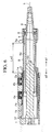
FIG. 1 is a cross-sectional view of a steering column according to an embodiment of the invention; -
FIG 2 is a perspective structure diagram of an outer tube of the steering column according to the embodiment; -
FIG. 3 is a cross-sectional view that shows an example of action of the steering column according to the embodiment; -
FIG. 4 is a cross-sectional view of a steering column according to an alternative embodiment; -
FIG. 5 is a perspective structure diagram of an outer tube of the steering column according to the alternative embodiment; -
FIG 6 is a cross-sectional view of a steering column according to another alternative embodiment; -
FIG. 7 is a cross-sectional view of an existing steering column; and -
FIG. 8 is a cross-sectional view of another example of an existing steering column. - Hereinafter, an embodiment of the invention will be described with reference to the accompanying drawings.
FIG. 1 shows the cross-sectional structure of a steering column according to the present embodiment. The structure of the steering column will be described with reference toFIG. 1 . Note that the configuration of the steering column shown inFIG. 1 for implementing telescopic action and impact absorbing action is basically similar to that of the steering column shown inFIG 8 . That is, in the steering column shown inFIG. 1 , asteering shaft 8 extends or retracts in the direction indicated by the arrow a1 or a2 shown in the drawing when anouter tube 3 is moved in the direction indicated by the arrow a1 or a2 shown in the drawing by an actuator (not shown). Such telescopic action is basically the same as described with reference toFIG. 7 andFIG 8 . In addition, for example, when a vehicle collides with an obstacle and an impact load acts on ahousing 1 and theouter tube 3, coupling of thetubes FIG. 7 andFIG 8 . - However, in the steering column, when coupling of the
tubes housing 1 contacts astopper 9a to restrict movement of thehousing 1 in the direction indicated by the arrow a1. That is, in the steering column, the amount of retraction (E/A stroke) at the time of absorbing an impact is set to a length indicated by Ls2 in the drawing when a relative positional relationship between thehousing 1 and theouter tube 3 is the positional relationship shown in the drawing. - As shown in
FIG 1 , in the steering column, almost the entireouter tube 3 is accommodated inside thehousing 1, and the center portion of the outer peripheral surface of theouter tube 3 is pressed by twotensioner bushings portion 3a that projects into a gap between theouter tube 3 and thehousing 1 is formed on the outer peripheral surface of the base end portion of theouter tube 3. - Next, the structure of the
outer tube 3 will be specifically described with reference toFIG 2 . As shown inFIG 2 , theouter tube 3 is a cylindrical member, and aplanar portion 3b is formed in the outer peripheral surface of theouter tube 3 while a curved surface portion 3c that forms the outer edge of the cylinder is left at the base end portion side. Theplanar portion 3b is formed by cutting out a portion of the outer peripheral surface into a planar shape from the upper end portion toward the base end portion. That is, theplanar portion 3b and the curved surface portion 3c are arranged side by side in a direction of an axis m. Thus, the projectingportion 3a is formed of a step portion between theseplanar portion 3b and curved surface portion 3c. When the projectingportion 3a is formed of the step portion between theplanar portion 3b and the curved surface portion 3c as described above, the projectingportion 3a may be formed by just forming theplanar portion 3b in the outer peripheral surface of theouter tube 3. Therefore, it is possible to easily form the projectingportion 3a. - Here, the
planar portion 3b is a portion pressed by thetensioner bushings tensioner bushings outer tube 3. Thus, a force acting from thetensioner bushings outer tube 3 may be increased. Therefore, the stiffness of the steering column increases. Meanwhile, the projectingportion 3a functions as a portion that restricts movement of theouter tube 3 in the direction indicated by the arrow a1 when theouter tube 3 moves in the direction indicated by the arrow a1 due to extending or retracting action. - Note that, in the present embodiment, the outside diameter of the
outer tube 3 is substantially equal to or slightly smaller than the inside diameter of each ofbearings FIG. 1 . Therefore, a slight gap is formed between the inner peripheral surface of each of thebearings planar portion 3b. - Next, an example of action of the steering column when the
outer tube 3 moves in the direction indicated by the arrow al will be described with reference toFIG. 3 . When theouter tube 3 moves in the direction indicated by the arrow a1, the projectingportion 3a passes in the gap between theouter tube 3 and thebearing 2a and then contacts the end surface of thetensioner bushing 4a. As a result, the positional relationship shown inFIG. 3 is established. The projectingportion 3a contacts the end surface of thetensioner bushing 4a to thereby restrict movement of theouter tube 3 in the direction indicated by the arrow a1. In the present embodiment, a movement restricting structure that restricts movement of theouter tube 3 in the direction indicated by the arrow a1 is formed of the projectingportion 3a of theouter tube 3 and thetensioner bushing 4a. The movement restricting structure prevents theouter tube 3 from slipping off from thehousing 1. - When the movement restricting structure is provided, for example, the retaining member of the existing art may be omitted. Therefore, the axial length of the steering column may be reduced by the length of the retaining member.
- In addition, in the present embodiment, the bolt for assembling the retaining member to the housing may also be omitted in addition to the retaining member. Therefore, the number of components may be reduced. As a result, it is possible to reduce the weight and cost of the steering column.
- Furthermore, in the present embodiment, the
tensioner bushing 4a is used as a member that restricts movement of the projectingportion 3a. Therefore, a member that restricts movement of the projectingportion 3a need not be provided in thehousing 1. Therefore, it is possible to simplify the structure of the steering column and reduce the cost of the steering column. - As described above, with the steering column according to the present embodiment, the following advantageous effects may be obtained.
- 1) The projecting
portion 3a is formed on theouter tube 3, and the projectingportion 3a is brought into contact with thetensioner bushing 4a to thereby restrict movement of theouter tube 3 in the direction indicated by the arrow a1. Thus, the above-described retaining member may be omitted. Therefore, even when the telescopic mechanism and the impact absorbing mechanism are provided, it is possible to downsize the steering column while ensuring an E/A stroke required at the time of absorbing an impact. Because the number of components is reduced, it is possible to reduce the weight and cost of the steering column. - 2) The
tensioner bushing 4a is used as a member that restricts movement of the projectingportion 3a. Thus, a member that restricts movement of the projectingportion 3a need not be provided in thehousing 1. Therefore, it is possible to simplify the structure of the steering column and reduce the cost of the steering column. - 3) The
planar portion 3b is formed in the outer peripheral surface of theouter tube 3, and the projectingportion 3a is formed of the step portion between theplanar portion 3b and the curved surface portion 3c. Thus, the projectingportion 3a may be provided by just forming theplanar portion 3b in the outer peripheral surface of theouter tube 3. Therefore, it is easy to form the projectingportion 3 a. - Note that the above-described embodiment may be modified into the following alternative embodiments.
In the above-described embodiment, the axial length of the steering column is reduced by the length of the omitted retaining member. Instead, for example, as shown inFIG. 4 , a structure in which the retaining member is just omitted may be employed. With this configuration, it is possible to obtain an advantageous effect that the E/A stroke Ls2 is made longer than the E/A stroke Ls1 without reducing the axial length of the steering column. - In the above-described embodiment, the projecting
portion 3a is formed of the step portion between theplanar portion 3b and the curved surface portion 3c that are formed in the outer peripheral surface of theouter tube 3. Instead, for example, as shown inFIG. 5 , aplanar portion 3d that extends from the upper end portion toward the base end portion may be formed in the outer peripheral surface of theouter tube 3 and then a projectingportion 3e may be formed on theplanar portion 3d. - In the above-described embodiment, the projecting
portion 3a is brought into contact with thetensioner bushing 4a that serves as a pressing member to thereby restrict movement of theouter tube 3. Instead, for example, the projection amount of the projectingportion 3a may be adjusted, and then the projectingportion 3a may be brought into contact with thebearing 2a to thereby restrict movement of theouter tube 3. In addition, for example, a projecting portion may be formed on the outer peripheral surface of the center portion of theouter tube 3 so as to be located between thetensioner bushings tensioner bushing 4b to thereby restrict movement of theouter tube 3. Furthermore, for example, a projecting portion may be newly formed on the inner wall surface of the housing 1and then the newly formed projecting portion may be used to restrict movement of the projectingportion 3a. Note that a method of newly forming a projecting portion on the inner wall surface of thehousing 1 may be an appropriately employed method, such as forming a projecting portion by machining the inner wall surface of thehousing 1 and embedding a bolt in the inner wall surface of thehousing 1. That is, any movement restricting structure may be employed as long as the movement restricting structure is formed of a projecting portion provided on the outer peripheral surface of theouter tube 3 so as to project into the gap between thehousing 1 and theouter tube 3 and a projecting portion provided on the inner wall surface of thehousing 1 so as to project into the gap and the projecting portion of theouter tube 3 contacts the projecting portion of thehousing 1 to thereby restrict movement of theouter tube 3 in the direction indicated by the arrow a1. - In the above-described embodiment, the projecting portion provided on the outer peripheral surface of the
outer tube 3 is brought into contact with the projecting portion provided on the inner wall surface of thehousing 1 to thereby restrict movement of theouter tube 3. Instead, for example, as shown inFIG 6 , agroove 1b may be formed in the inner wall surface of thehousing 1, a projectingportion 3f to be inserted in thegroove 1b may be formed on the outer peripheral surface of theouter tube 3, and the projectingportion 3f may contact the inner wall surface of thegroove 1b in the direction indicated by the arrow a1 to thereby restrict movement of theouter tube 3 in the direction indicated by the arrow al. That is, any movement restricting structure may be employed as long as the movement restricting structure is provided at a portion at which the inner wall surface of thehousing 1 faces the outer wall surface of theouter tube 3 and restricts movement of theouter tube 3 in the direction of the axis m. - Next, a technical idea derived from the above embodiment and its alternative embodiments will be appended.
- 1) A steering column is configured in such a manner that the projecting portion of the housing is formed by machining the inner peripheral surface of the housing. With the above configuration, the projecting portion of the housing may be easily formed.
A steering column includes a telescopic mechanism and an impact absorbing mechanism. The steering column includes an inner tube (6) that accommodates a steering shaft (8) and an outer tube (3) that is held by a housing (1) and that is coupled with the inner tube (6). A projecting portion (3a) is formed on an outer peripheral surface of a base end portion of the outer tube (3) and then the projecting portion (3a) is brought into contact with a tensioner bushing (4a) to thereby restrict movement of the outer tube (3) in a direction indicated by an arrow (a1), thus preventing the outer tube (3) from slipping off from the housing (1).
Claims (4)
- A steering column comprising:an inner tube that accommodates a steering shaft which is a rotating shaft of a steering wheel of a vehicle, and that moves in an axial direction of the steering shaft together with the steering shaft;an outer tube that is held by a housing supported by a vehicle body so as to be movable in the axial direction, and that is coupled with the inner tube;a telescopic mechanism that adjusts a position of the steering wheel in the axial direction as the inner tube and the outer tube in a coupled state move in the axial direction together with the steering shaft; andan impact absorbing mechanism that absorbs impact energy when coupling of the inner tube and the outer tube is cancelled to retract the steering shaft by a predetermined amount in the axial direction upon application of a force exceeding a coupling force, which couples the inner tube and the outer tube with each other, on the steering shaft or the housing, whereinthe steering column has a movement restricting structure that restricts movement of the outer tube in the axial direction, at a portion at which an inner peripheral surface of the housing faces an outer peripheral surface of the outer tube.
- The steering column according to claim 1, wherein:the movement restricting structure is formed of a projecting portion that is provided on the outer peripheral surface of the outer tube so as to project into a gap between the housing and the outer tube and a projecting portion that is provided on an inner peripheral surface of the housing so as to project into the gap; andmovement of the outer tube in the axial direction is restricted when the projecting portion of the outer tube contacts the projecting portion of the housing.
- The steering column according to claim 2, wherein:the housing includes a pressing member that is arranged so as to project from the inner peripheral surface of the housing and contact the outer peripheral surface of the outer tube and that presses the outer peripheral surface of the outer tube; andthe pressing member constitutes the projecting portion of the housing.
- The steering column according to claim 3, wherein:the outer tube is a cylindrical member and is formed in such a manner that a curved surface portion that forms an outer edge of the cylindrical shape and a planar portion that is formed by cutting out a portion of the outer peripheral surface into a planar shape are arranged side by side in the axial direction on the outer peripheral surface of the outer tube; andthe projecting portion of the outer tube is formed of a step portion that is formed between the curved surface portion and the planar portion.
Applications Claiming Priority (1)
| Application Number | Priority Date | Filing Date | Title |
|---|---|---|---|
| JP2009191933A JP2011042262A (en) | 2009-08-21 | 2009-08-21 | Steering column |
Publications (3)
| Publication Number | Publication Date |
|---|---|
| EP2287063A2 true EP2287063A2 (en) | 2011-02-23 |
| EP2287063A3 EP2287063A3 (en) | 2012-03-21 |
| EP2287063B1 EP2287063B1 (en) | 2013-04-03 |
Family
ID=43037732
Family Applications (1)
| Application Number | Title | Priority Date | Filing Date |
|---|---|---|---|
| EP10173384A Not-in-force EP2287063B1 (en) | 2009-08-21 | 2010-08-19 | Steering column |
Country Status (4)
| Country | Link |
|---|---|
| US (1) | US20110041643A1 (en) |
| EP (1) | EP2287063B1 (en) |
| JP (1) | JP2011042262A (en) |
| CN (1) | CN101992800A (en) |
Cited By (1)
| Publication number | Priority date | Publication date | Assignee | Title |
|---|---|---|---|---|
| FR3105773A1 (en) * | 2019-12-31 | 2021-07-02 | Robert Bosch Automotive Steering Vendôme | steering column sleeve comprising a system for adjusting a relative position between two tubes |
Families Citing this family (13)
| Publication number | Priority date | Publication date | Assignee | Title |
|---|---|---|---|---|
| JP5146474B2 (en) * | 2010-02-22 | 2013-02-20 | 日本精工株式会社 | Steering column device and its assembly method |
| US8955407B2 (en) * | 2011-05-30 | 2015-02-17 | Nsk Ltd. | Steering apparatus |
| DE102011112079B4 (en) * | 2011-09-01 | 2014-02-06 | Audi Ag | Steering wheel arrangement for a motor vehicle |
| JP5811735B2 (en) * | 2011-09-26 | 2015-11-11 | アイシン精機株式会社 | Vehicle steering device |
| US20130133461A1 (en) * | 2011-11-30 | 2013-05-30 | Nexteer (Beijing) Technology Co., Ltd. | Energy absorbing steering column assembly |
| JP6179347B2 (en) * | 2013-10-25 | 2017-08-16 | アイシン精機株式会社 | Vehicle steering device |
| CN104554421A (en) * | 2014-12-30 | 2015-04-29 | 耐世特汽车系统(苏州)有限公司 | Steering column protecting pipe |
| DE102015000027A1 (en) | 2015-01-08 | 2016-07-14 | Thyssenkrupp Ag | Steering column with flexibly mountable bearing seat |
| DE102015002889B3 (en) * | 2015-03-09 | 2016-05-12 | Thyssenkrupp Ag | Adjustable steering column with improved rigidity |
| DE102015216326B4 (en) * | 2015-08-26 | 2016-09-08 | Thyssenkrupp Ag | Motor-adjustable steering column for a motor vehicle |
| US10654510B2 (en) * | 2017-08-28 | 2020-05-19 | Fuji Kiko Co., Ltd. | Electric steering column apparatus |
| CN109501852B (en) * | 2018-12-19 | 2021-07-30 | 芜湖世特瑞转向系统有限公司 | Electric four-way adjustable steering column |
| CN117396392A (en) | 2021-06-25 | 2024-01-12 | 株式会社捷太格特 | Steering column device |
Citations (1)
| Publication number | Priority date | Publication date | Assignee | Title |
|---|---|---|---|---|
| JP2007168569A (en) | 2005-12-21 | 2007-07-05 | Aisin Seiki Co Ltd | Energy absorbing steering column |
Family Cites Families (10)
| Publication number | Priority date | Publication date | Assignee | Title |
|---|---|---|---|---|
| JPS56120458A (en) * | 1980-02-25 | 1981-09-21 | Aisin Seiki Co Ltd | Mechanism for adjusting axial position of steering wheel |
| JPS5947574U (en) * | 1982-09-24 | 1984-03-29 | トヨタ自動車株式会社 | telescopic steering device |
| US4805478A (en) * | 1987-06-26 | 1989-02-21 | General Motors Corporation | Steering column for vehicle with multitube energy absorbing mast jacket |
| US5267480A (en) * | 1992-07-10 | 1993-12-07 | Douglas Autotech Corporation | Telescoping column |
| DE19504036C1 (en) * | 1995-02-08 | 1996-06-27 | Lemfoerder Metallwaren Ag | Safety steering shaft |
| JP2942496B2 (en) * | 1996-03-07 | 1999-08-30 | 株式会社椿本チエイン | Detent mechanism for screw type linear actuator |
| JP2002046625A (en) * | 2000-08-04 | 2002-02-12 | Nsk Ltd | Telescopic steering column |
| JP5125253B2 (en) * | 2007-06-26 | 2013-01-23 | アイシン精機株式会社 | Vehicle steering device |
| JP2009107540A (en) * | 2007-10-31 | 2009-05-21 | Nsk Ltd | Position adjustment type steering device |
| DE102007060149A1 (en) * | 2007-12-13 | 2009-06-18 | GM Global Technology Operations, Inc., Detroit | Telescopic steering spindle assembly |
-
2009
- 2009-08-21 JP JP2009191933A patent/JP2011042262A/en active Pending
-
2010
- 2010-07-30 US US12/847,309 patent/US20110041643A1/en not_active Abandoned
- 2010-08-19 EP EP10173384A patent/EP2287063B1/en not_active Not-in-force
- 2010-08-19 CN CN2010102594326A patent/CN101992800A/en active Pending
Patent Citations (1)
| Publication number | Priority date | Publication date | Assignee | Title |
|---|---|---|---|---|
| JP2007168569A (en) | 2005-12-21 | 2007-07-05 | Aisin Seiki Co Ltd | Energy absorbing steering column |
Cited By (2)
| Publication number | Priority date | Publication date | Assignee | Title |
|---|---|---|---|---|
| FR3105773A1 (en) * | 2019-12-31 | 2021-07-02 | Robert Bosch Automotive Steering Vendôme | steering column sleeve comprising a system for adjusting a relative position between two tubes |
| GB2592734B (en) * | 2019-12-31 | 2022-08-03 | Robert Bosch Automotive Steering Vendome | Steering column sleeve comprising a system for adjusting a relative position between two tubes |
Also Published As
| Publication number | Publication date |
|---|---|
| CN101992800A (en) | 2011-03-30 |
| EP2287063A3 (en) | 2012-03-21 |
| US20110041643A1 (en) | 2011-02-24 |
| JP2011042262A (en) | 2011-03-03 |
| EP2287063B1 (en) | 2013-04-03 |
Similar Documents
| Publication | Publication Date | Title |
|---|---|---|
| EP2287063B1 (en) | Steering column | |
| JP5369537B2 (en) | Energy absorbing steering column | |
| JP2019127176A (en) | Steering device | |
| EP2025576B1 (en) | Steering wheel position adjustment device | |
| US7527295B2 (en) | Energy absorbing steering column | |
| CN110077451B (en) | Steering device | |
| KR20160106236A (en) | Steering Column for Vehicle | |
| JP6417796B2 (en) | Steering device | |
| JP2016137772A (en) | Steering device | |
| US20040217581A1 (en) | Energy absorber for motor vehicle steering column | |
| JP5228984B2 (en) | Energy absorbing steering column | |
| CN210191573U (en) | Energy-absorbing steering column and automobile | |
| CN101945795A (en) | Impact-absorbing steering device | |
| WO2005123484A1 (en) | Shock absorbing device at stroke end of rack | |
| JP5268027B2 (en) | Energy absorbing steering column | |
| JP6179347B2 (en) | Vehicle steering device | |
| KR101138160B1 (en) | Impact Asorption Steering Apparatus | |
| JP6132147B2 (en) | Rack guide device | |
| JP6481374B2 (en) | Energy absorbing steering column | |
| JP3938314B2 (en) | Steering device | |
| KR102246687B1 (en) | Steering Column for Vehicle | |
| JP2009107540A (en) | Position adjustment type steering device | |
| KR102245792B1 (en) | Motor driven power steering | |
| JP2000296743A (en) | Shock absorbing front underrun protector | |
| JP3930253B2 (en) | Shock absorbing steering device |
Legal Events
| Date | Code | Title | Description |
|---|---|---|---|
| PUAI | Public reference made under article 153(3) epc to a published international application that has entered the european phase |
Free format text: ORIGINAL CODE: 0009012 |
|
| AK | Designated contracting states |
Kind code of ref document: A2 Designated state(s): AL AT BE BG CH CY CZ DE DK EE ES FI FR GB GR HR HU IE IS IT LI LT LU LV MC MK MT NL NO PL PT RO SE SI SK SM TR |
|
| AX | Request for extension of the european patent |
Extension state: BA ME RS |
|
| PUAL | Search report despatched |
Free format text: ORIGINAL CODE: 0009013 |
|
| AK | Designated contracting states |
Kind code of ref document: A3 Designated state(s): AL AT BE BG CH CY CZ DE DK EE ES FI FR GB GR HR HU IE IS IT LI LT LU LV MC MK MT NL NO PL PT RO SE SI SK SM TR |
|
| AX | Request for extension of the european patent |
Extension state: BA ME RS |
|
| RIC1 | Information provided on ipc code assigned before grant |
Ipc: B62D 1/185 20060101AFI20120215BHEP Ipc: B62D 1/19 20060101ALI20120215BHEP |
|
| 17P | Request for examination filed |
Effective date: 20120712 |
|
| GRAP | Despatch of communication of intention to grant a patent |
Free format text: ORIGINAL CODE: EPIDOSNIGR1 |
|
| GRAS | Grant fee paid |
Free format text: ORIGINAL CODE: EPIDOSNIGR3 |
|
| GRAA | (expected) grant |
Free format text: ORIGINAL CODE: 0009210 |
|
| AK | Designated contracting states |
Kind code of ref document: B1 Designated state(s): AL AT BE BG CH CY CZ DE DK EE ES FI FR GB GR HR HU IE IS IT LI LT LU LV MC MK MT NL NO PL PT RO SE SI SK SM TR |
|
| REG | Reference to a national code |
Ref country code: GB Ref legal event code: FG4D |
|
| REG | Reference to a national code |
Ref country code: CH Ref legal event code: EP Ref country code: AT Ref legal event code: REF Ref document number: 604520 Country of ref document: AT Kind code of ref document: T Effective date: 20130415 |
|
| REG | Reference to a national code |
Ref country code: IE Ref legal event code: FG4D |
|
| REG | Reference to a national code |
Ref country code: DE Ref legal event code: R096 Ref document number: 602010006028 Country of ref document: DE Effective date: 20130606 |
|
| REG | Reference to a national code |
Ref country code: AT Ref legal event code: MK05 Ref document number: 604520 Country of ref document: AT Kind code of ref document: T Effective date: 20130403 |
|
| PG25 | Lapsed in a contracting state [announced via postgrant information from national office to epo] |
Ref country code: SI Free format text: LAPSE BECAUSE OF FAILURE TO SUBMIT A TRANSLATION OF THE DESCRIPTION OR TO PAY THE FEE WITHIN THE PRESCRIBED TIME-LIMIT Effective date: 20130403 |
|
| REG | Reference to a national code |
Ref country code: NL Ref legal event code: VDEP Effective date: 20130403 |
|
| REG | Reference to a national code |
Ref country code: LT Ref legal event code: MG4D |
|
| PG25 | Lapsed in a contracting state [announced via postgrant information from national office to epo] |
Ref country code: PT Free format text: LAPSE BECAUSE OF FAILURE TO SUBMIT A TRANSLATION OF THE DESCRIPTION OR TO PAY THE FEE WITHIN THE PRESCRIBED TIME-LIMIT Effective date: 20130805 Ref country code: BE Free format text: LAPSE BECAUSE OF FAILURE TO SUBMIT A TRANSLATION OF THE DESCRIPTION OR TO PAY THE FEE WITHIN THE PRESCRIBED TIME-LIMIT Effective date: 20130403 Ref country code: NO Free format text: LAPSE BECAUSE OF FAILURE TO SUBMIT A TRANSLATION OF THE DESCRIPTION OR TO PAY THE FEE WITHIN THE PRESCRIBED TIME-LIMIT Effective date: 20130703 Ref country code: FI Free format text: LAPSE BECAUSE OF FAILURE TO SUBMIT A TRANSLATION OF THE DESCRIPTION OR TO PAY THE FEE WITHIN THE PRESCRIBED TIME-LIMIT Effective date: 20130403 Ref country code: IS Free format text: LAPSE BECAUSE OF FAILURE TO SUBMIT A TRANSLATION OF THE DESCRIPTION OR TO PAY THE FEE WITHIN THE PRESCRIBED TIME-LIMIT Effective date: 20130803 Ref country code: ES Free format text: LAPSE BECAUSE OF FAILURE TO SUBMIT A TRANSLATION OF THE DESCRIPTION OR TO PAY THE FEE WITHIN THE PRESCRIBED TIME-LIMIT Effective date: 20130714 Ref country code: AT Free format text: LAPSE BECAUSE OF FAILURE TO SUBMIT A TRANSLATION OF THE DESCRIPTION OR TO PAY THE FEE WITHIN THE PRESCRIBED TIME-LIMIT Effective date: 20130403 Ref country code: NL Free format text: LAPSE BECAUSE OF FAILURE TO SUBMIT A TRANSLATION OF THE DESCRIPTION OR TO PAY THE FEE WITHIN THE PRESCRIBED TIME-LIMIT Effective date: 20130403 Ref country code: GR Free format text: LAPSE BECAUSE OF FAILURE TO SUBMIT A TRANSLATION OF THE DESCRIPTION OR TO PAY THE FEE WITHIN THE PRESCRIBED TIME-LIMIT Effective date: 20130704 Ref country code: LT Free format text: LAPSE BECAUSE OF FAILURE TO SUBMIT A TRANSLATION OF THE DESCRIPTION OR TO PAY THE FEE WITHIN THE PRESCRIBED TIME-LIMIT Effective date: 20130403 Ref country code: SE Free format text: LAPSE BECAUSE OF FAILURE TO SUBMIT A TRANSLATION OF THE DESCRIPTION OR TO PAY THE FEE WITHIN THE PRESCRIBED TIME-LIMIT Effective date: 20130403 |
|
| PG25 | Lapsed in a contracting state [announced via postgrant information from national office to epo] |
Ref country code: HR Free format text: LAPSE BECAUSE OF FAILURE TO SUBMIT A TRANSLATION OF THE DESCRIPTION OR TO PAY THE FEE WITHIN THE PRESCRIBED TIME-LIMIT Effective date: 20130403 Ref country code: BG Free format text: LAPSE BECAUSE OF FAILURE TO SUBMIT A TRANSLATION OF THE DESCRIPTION OR TO PAY THE FEE WITHIN THE PRESCRIBED TIME-LIMIT Effective date: 20130703 Ref country code: PL Free format text: LAPSE BECAUSE OF FAILURE TO SUBMIT A TRANSLATION OF THE DESCRIPTION OR TO PAY THE FEE WITHIN THE PRESCRIBED TIME-LIMIT Effective date: 20130403 Ref country code: CY Free format text: LAPSE BECAUSE OF FAILURE TO SUBMIT A TRANSLATION OF THE DESCRIPTION OR TO PAY THE FEE WITHIN THE PRESCRIBED TIME-LIMIT Effective date: 20130403 Ref country code: LV Free format text: LAPSE BECAUSE OF FAILURE TO SUBMIT A TRANSLATION OF THE DESCRIPTION OR TO PAY THE FEE WITHIN THE PRESCRIBED TIME-LIMIT Effective date: 20130403 |
|
| PG25 | Lapsed in a contracting state [announced via postgrant information from national office to epo] |
Ref country code: SK Free format text: LAPSE BECAUSE OF FAILURE TO SUBMIT A TRANSLATION OF THE DESCRIPTION OR TO PAY THE FEE WITHIN THE PRESCRIBED TIME-LIMIT Effective date: 20130403 Ref country code: EE Free format text: LAPSE BECAUSE OF FAILURE TO SUBMIT A TRANSLATION OF THE DESCRIPTION OR TO PAY THE FEE WITHIN THE PRESCRIBED TIME-LIMIT Effective date: 20130403 Ref country code: CZ Free format text: LAPSE BECAUSE OF FAILURE TO SUBMIT A TRANSLATION OF THE DESCRIPTION OR TO PAY THE FEE WITHIN THE PRESCRIBED TIME-LIMIT Effective date: 20130403 Ref country code: DK Free format text: LAPSE BECAUSE OF FAILURE TO SUBMIT A TRANSLATION OF THE DESCRIPTION OR TO PAY THE FEE WITHIN THE PRESCRIBED TIME-LIMIT Effective date: 20130403 |
|
| PLBE | No opposition filed within time limit |
Free format text: ORIGINAL CODE: 0009261 |
|
| STAA | Information on the status of an ep patent application or granted ep patent |
Free format text: STATUS: NO OPPOSITION FILED WITHIN TIME LIMIT |
|
| PG25 | Lapsed in a contracting state [announced via postgrant information from national office to epo] |
Ref country code: IT Free format text: LAPSE BECAUSE OF FAILURE TO SUBMIT A TRANSLATION OF THE DESCRIPTION OR TO PAY THE FEE WITHIN THE PRESCRIBED TIME-LIMIT Effective date: 20130403 Ref country code: RO Free format text: LAPSE BECAUSE OF FAILURE TO SUBMIT A TRANSLATION OF THE DESCRIPTION OR TO PAY THE FEE WITHIN THE PRESCRIBED TIME-LIMIT Effective date: 20130403 |
|
| REG | Reference to a national code |
Ref country code: DE Ref legal event code: R119 Ref document number: 602010006028 Country of ref document: DE |
|
| 26N | No opposition filed |
Effective date: 20140106 |
|
| REG | Reference to a national code |
Ref country code: DE Ref legal event code: R097 Ref document number: 602010006028 Country of ref document: DE Effective date: 20140106 |
|
| PG25 | Lapsed in a contracting state [announced via postgrant information from national office to epo] |
Ref country code: MC Free format text: LAPSE BECAUSE OF FAILURE TO SUBMIT A TRANSLATION OF THE DESCRIPTION OR TO PAY THE FEE WITHIN THE PRESCRIBED TIME-LIMIT Effective date: 20130403 Ref country code: DE Free format text: LAPSE BECAUSE OF NON-PAYMENT OF DUE FEES Effective date: 20140301 |
|
| REG | Reference to a national code |
Ref country code: IE Ref legal event code: MM4A |
|
| REG | Reference to a national code |
Ref country code: DE Ref legal event code: R119 Ref document number: 602010006028 Country of ref document: DE Effective date: 20140301 |
|
| REG | Reference to a national code |
Ref country code: FR Ref legal event code: ST Effective date: 20140430 |
|
| PG25 | Lapsed in a contracting state [announced via postgrant information from national office to epo] |
Ref country code: IE Free format text: LAPSE BECAUSE OF NON-PAYMENT OF DUE FEES Effective date: 20130819 |
|
| PG25 | Lapsed in a contracting state [announced via postgrant information from national office to epo] |
Ref country code: FR Free format text: LAPSE BECAUSE OF NON-PAYMENT OF DUE FEES Effective date: 20130902 |
|
| REG | Reference to a national code |
Ref country code: CH Ref legal event code: PL |
|
| GBPC | Gb: european patent ceased through non-payment of renewal fee |
Effective date: 20140819 |
|
| PG25 | Lapsed in a contracting state [announced via postgrant information from national office to epo] |
Ref country code: CH Free format text: LAPSE BECAUSE OF NON-PAYMENT OF DUE FEES Effective date: 20140831 Ref country code: LI Free format text: LAPSE BECAUSE OF NON-PAYMENT OF DUE FEES Effective date: 20140831 |
|
| PG25 | Lapsed in a contracting state [announced via postgrant information from national office to epo] |
Ref country code: SM Free format text: LAPSE BECAUSE OF FAILURE TO SUBMIT A TRANSLATION OF THE DESCRIPTION OR TO PAY THE FEE WITHIN THE PRESCRIBED TIME-LIMIT Effective date: 20130403 |
|
| PG25 | Lapsed in a contracting state [announced via postgrant information from national office to epo] |
Ref country code: MT Free format text: LAPSE BECAUSE OF FAILURE TO SUBMIT A TRANSLATION OF THE DESCRIPTION OR TO PAY THE FEE WITHIN THE PRESCRIBED TIME-LIMIT Effective date: 20130403 Ref country code: TR Free format text: LAPSE BECAUSE OF FAILURE TO SUBMIT A TRANSLATION OF THE DESCRIPTION OR TO PAY THE FEE WITHIN THE PRESCRIBED TIME-LIMIT Effective date: 20130403 |
|
| PG25 | Lapsed in a contracting state [announced via postgrant information from national office to epo] |
Ref country code: MK Free format text: LAPSE BECAUSE OF FAILURE TO SUBMIT A TRANSLATION OF THE DESCRIPTION OR TO PAY THE FEE WITHIN THE PRESCRIBED TIME-LIMIT Effective date: 20130403 Ref country code: GB Free format text: LAPSE BECAUSE OF NON-PAYMENT OF DUE FEES Effective date: 20140819 Ref country code: HU Free format text: LAPSE BECAUSE OF FAILURE TO SUBMIT A TRANSLATION OF THE DESCRIPTION OR TO PAY THE FEE WITHIN THE PRESCRIBED TIME-LIMIT; INVALID AB INITIO Effective date: 20100819 Ref country code: LU Free format text: LAPSE BECAUSE OF NON-PAYMENT OF DUE FEES Effective date: 20130819 |
|
| PG25 | Lapsed in a contracting state [announced via postgrant information from national office to epo] |
Ref country code: AL Free format text: LAPSE BECAUSE OF FAILURE TO SUBMIT A TRANSLATION OF THE DESCRIPTION OR TO PAY THE FEE WITHIN THE PRESCRIBED TIME-LIMIT Effective date: 20130403 |