EP2286130B1 - Manifold structure having adjustable brackets - Google Patents
Manifold structure having adjustable brackets Download PDFInfo
- Publication number
- EP2286130B1 EP2286130B1 EP09746816.9A EP09746816A EP2286130B1 EP 2286130 B1 EP2286130 B1 EP 2286130B1 EP 09746816 A EP09746816 A EP 09746816A EP 2286130 B1 EP2286130 B1 EP 2286130B1
- Authority
- EP
- European Patent Office
- Prior art keywords
- pipe
- frame construction
- support bracket
- connector
- securing means
- Prior art date
- Legal status (The legal status is an assumption and is not a legal conclusion. Google has not performed a legal analysis and makes no representation as to the accuracy of the status listed.)
- Not-in-force
Links
- 238000010276 construction Methods 0.000 claims description 44
- 238000009434 installation Methods 0.000 claims description 15
- 238000004519 manufacturing process Methods 0.000 claims description 13
- 238000000034 method Methods 0.000 claims description 5
- 235000004507 Abies alba Nutrition 0.000 claims description 4
- 241000191291 Abies alba Species 0.000 claims description 4
- 230000008878 coupling Effects 0.000 description 3
- 238000010168 coupling process Methods 0.000 description 3
- 238000005859 coupling reaction Methods 0.000 description 3
- 238000004891 communication Methods 0.000 description 2
- 239000004020 conductor Substances 0.000 description 2
- 241001317177 Glossostigma diandrum Species 0.000 description 1
- 239000012530 fluid Substances 0.000 description 1
- 239000000463 material Substances 0.000 description 1
- 230000013011 mating Effects 0.000 description 1
- 125000006850 spacer group Chemical group 0.000 description 1
Images

Classifications
-
- E—FIXED CONSTRUCTIONS
- E21—EARTH OR ROCK DRILLING; MINING
- E21B—EARTH OR ROCK DRILLING; OBTAINING OIL, GAS, WATER, SOLUBLE OR MELTABLE MATERIALS OR A SLURRY OF MINERALS FROM WELLS
- E21B43/00—Methods or apparatus for obtaining oil, gas, water, soluble or meltable materials or a slurry of minerals from wells
- E21B43/01—Methods or apparatus for obtaining oil, gas, water, soluble or meltable materials or a slurry of minerals from wells specially adapted for obtaining from underwater installations
- E21B43/013—Connecting a production flow line to an underwater well head
-
- Y—GENERAL TAGGING OF NEW TECHNOLOGICAL DEVELOPMENTS; GENERAL TAGGING OF CROSS-SECTIONAL TECHNOLOGIES SPANNING OVER SEVERAL SECTIONS OF THE IPC; TECHNICAL SUBJECTS COVERED BY FORMER USPC CROSS-REFERENCE ART COLLECTIONS [XRACs] AND DIGESTS
- Y10—TECHNICAL SUBJECTS COVERED BY FORMER USPC
- Y10T—TECHNICAL SUBJECTS COVERED BY FORMER US CLASSIFICATION
- Y10T29/00—Metal working
- Y10T29/49—Method of mechanical manufacture
- Y10T29/49826—Assembling or joining
- Y10T29/49947—Assembling or joining by applying separate fastener
Definitions
- the present invention relates to a manifold structure to be placed on a seabed adapted to be connected to one or more Christmas trees for the production of oil and gas, said manifold structure including a frame construction, a number of pipes, pipe bends and possible valves, deployed in a pipe system having a number of pipe terminations projecting upwardly from the frame construction, said frame construction is provided with a number of support brackets for respective connector porches associated with said pipe terminations.
- the invention also relates to a method for the manufacture of a manifold structure of the kind stated above.
- manifold structures are designed to be placed on the sea bed and are to be connected to one or more Christmas trees for the production of oil and/or gas.
- the interconnecting operation takes place in that jumpers, or lines, are lowered from the surface toward connecting points on the manifold structure and the Christmas trees.
- the manifold structure is often constructed by a number of girders and braces suitably arranged in a more or less open frame construction which in turn can be set on a base located on the sea bed, for example a suction anchor or mud mat.
- the piping includes a number of headers, branch pipes, bends and valves.
- the male part is in one way or another secured to a support bracket on the frame construction.
- each support bracket has been fixedly welded to the frame construction as if it was an integrated part thereof. This has resulted in problems if the pipes are not precisely manufactured with regard to pipe lengths and bend angles. By presumption, these parts are to fit precisely to the support brackets. When this has not been the case, it has been necessary to cut loose the bracket and have it displaced such that the bracket fits in with the connector flange, and then weld the bracket once again to the frame construction.
- Publication GB1211781 discloses a subsea foundation unit providing a rigid level base for a subsea body on a marine bottom comprising a base structure, a conductor pipe template structure and a removable handling structure.
- the conductor pipe template structure is adapted to be installed on the base structure.
- Publication US6312193 discloses a method for coupling a bottom-based pipeline to an riser pipe or pipeline and includes a transportable frame carrying coupling stations between spaced ends of the undersea pipeline and a frame including a communication pipeline between said coupling stations.
- Publication NO20063911 discloses an apparatus for connecting to a subsea wellbore having a manifold and a choke body.
- the apparatus comprising a frame adapted to land on the manifold in a first stage of a connection and a conduit system with conduit means adapted to be brought into fluid communication with the choke body in a second stage of the connection.
- One object with the present invention has been to reduce the requirements to the tolerances in the manufacture of the main pipes. Thus, it will be possible to cut down the use of time and reduce the manufacturing costs. In addition, deformations applied to the pipes due to manufacturing tolerances will not take place. At the same time, they will be easier to install without a need to use forces in order to force the pipes in place.
- Another object has been to be able to perform parallel production of the frame construction and the components, for example the support brackets and the pipes. Thus, a shorter manufacturing time during module construction is obtained.
- Still another object has been to "standardize" components to be used on the frame construction such that these can be constructed and prepared independently of when the frame construction is constructed.
- Still another object has been to improve the access to internal manifold structure during manufacturing thereof, such as good access during installation and assembly of pipes and bends.
- each support bracket is made as a separate, standardized unit that includes several securing means for releasable installation to the frame construction at a position over the respective pipe termination, said securing means are designed for confined adjustability in height and lateral direction for adaption to a preinstalled pipe termination.
- the securing means can include bolts/ bolt connections.
- Bolts/bolt connections can extend through oblong apertures in order to obtain said adjustability.
- a support bracket designed for installation on a manifold structure as stated above is also provided, where the support bracket is designed to support a connector porch adapted to retain a pipe end having a connector flange, which in particular is distinguished in that the support bracket includes several securing means for releasable installation to the frame construction, which securing means are designed for defined adjustability in height and lateral direction for adaption to a preinstalled pipe spool having said connector flange.
- a method of the introductory said kind is also provided, which is distinguished in that the piping firstly is installed in place within the frame construction and having pipe terminations projecting outwards from the frame construction and directed upwards, that a support bracket is placed at respective pipe terminations and coarse adjusted relative to the pipe terminations, that a connector porch is installed over respective pipe terminations, that each connector porch is fixedly bolted to an associated pipe termination and then welded to an associated support bracket, said support bracket subsequently being fine adjusted and finally fixed to the frame construction.
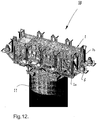
- a typical and complete manifold structure 10 is illustrated in fig. 12 and can be conferred to as the figures 1-11 are described. This is to ease the understanding of the invention and be able to recognize the interrelation where the individual parts and components are to be placed within the manifold structure and in relation to each other.
- the shown manifold structure 10 is fixed to a suction anchor 11 which in turn is placed on the sea bed.
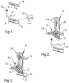
- figure 1 shows a partial view of a manifold structure, more precisely a bottom part 1a and a top part 1b of the frame construction 1 of the manifold structure 10. Then frame construction 1 is of substantial dimensions, often several tenths of meters long. An angled pipe 2, or a bend, having a connector flange 2a is illustrated as located in the frame construction 1. Further, the bottom part 1a has a bracket structure 3 with oblong apertures 3a designed for later adjustable installation of components on the bracket structure 3. The top part 1b has a corresponding support structure 4 having apertures 4a designed for later installation of said components on the support structure 4.
- Figure 2 shows a support bracket 5 which is about to be landed on the frame construction 1.
- the support bracket 5 has a substantially vertically extending back structure 5a, one substantially horizontally extending support structure 5b, inclined braces 5c and a guiding structure 5d.
- the support structure 5b has a central aperture 5e for receipt of the bend 2.
- Figure 3 shows the support bracket 5 landed on the bracket structure 3 and rests thereon.
- the bend 2 fits through the aperture 5e in the support structure 5b and in turn, the connector flange 2a extends upwards from the plane of the support structure 5b and stands ready to receive a mating component.
- Figure 4 shows such a component in the form of a connector porch 6 (guide cone) which is to be lowered down over the connector flange 2a.
- a detailed view A in enlarged scale is shown that illustrates the lower mount between the support bracket 5 and the support structure 3 on the bottom part 1a.
- a number of bolts B are used to secure the parts together. Oblong recesses in the parts enable the parts to be adjusted in respect of each other in the horizontal plane.
- the detailed view B in figure 4 shows an upper securing means 5f on the back structure 5a in enlarged scale.
- the securing means 5f has oblong apertures 5g to be able to make height adjustment. If height adjustment is necessary, shims or spacers can be installed between respective flange parts on the support bracket 5 and the bracket structure 3, i.e. on that spot depicted in detailed view A in figure 4 .
- Figure 5 shows the connector porch 6 completely landed onto the support structure 5b.
- the connector porch 6 has a bottom plate 6a which provides some freedom of motion in the horizontal plane to obtain correct position in respect of the connector flange 2a.
- the bottom plate 6a rests against the top surface of the support structure 5b.
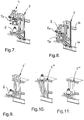
- Figure 6 shows the first step in the finishing phase during installation of a vertical connector module 7 (VCM) onto the connector porch 6 which in turn is arranged on the support bracket 5 on the frame construction 1.
- the connector module 7 is landed from above and positioned such that the female part stands right above the connector porch 6.
- the connector porch 6 thus constitutes the male part.
- the connector module 7 has guiding means 7a which are design for cooperation with the guide structure 5d which is arranged on the back structure 5a of the support bracket 5.
- the guiding means 7a guides the connector module 7 against the connector porch 6 by means of the guiding structure 5d.
- inclined faces 5d' are provided to ease the introduction of the guiding means 7a into the guiding structure 5a.
- Figure 7 shows the next step of the finishing phase.
- the connector module 7 has engaged the guiding structure 5d via the guiding means 7a and is guided further into place toward the connector porch 6 on the support bracket 5.
- the connector module 7 includes a clamp connector 7b which makes up the final connection between the flanges.
- Figure 8 shows the finished installation of the connector module 7 on the connector porch 6 on the support bracket 5 on the frame construction 1.
- the connector module 7 includes a pipe bend 8 having a connector flange 8a which is used for later connection of a pipe line which is tied in toward this flange 8a.
- Figure 9 to 11 show three variants 5'; 5"; 5'" among many possible embodiments of a support bracket according to the present invention.
- the piping (pipe system) is installed in place in the frame construction. All external connecting points in the form of pipe terminations project outwards from the body of the frame construction.
- the pipe terminations are further such designed that they are pointing upwards.
- each bracket is placed over respective pipe terminations. Each bracket is coarse adjusted relative to the associated pipe termination.
- each connector porch is placed over respective connector flange.
- Each connector porch is in turn bolted in place on corresponding connector flange.
- the connector porch is welded to its associated support bracket.
- each bracket is fine adjusted and eventually fixed by means of bolts and nuts to the frame construction.
Landscapes
- Life Sciences & Earth Sciences (AREA)
- Engineering & Computer Science (AREA)
- Geology (AREA)
- Mining & Mineral Resources (AREA)
- Physics & Mathematics (AREA)
- Environmental & Geological Engineering (AREA)
- Fluid Mechanics (AREA)
- General Life Sciences & Earth Sciences (AREA)
- Geochemistry & Mineralogy (AREA)
- Supports For Pipes And Cables (AREA)
- Cooling, Air Intake And Gas Exhaust, And Fuel Tank Arrangements In Propulsion Units (AREA)
Description
- The present invention relates to a manifold structure to be placed on a seabed adapted to be connected to one or more Christmas trees for the production of oil and gas, said manifold structure including a frame construction, a number of pipes, pipe bends and possible valves, deployed in a pipe system having a number of pipe terminations projecting upwardly from the frame construction, said frame construction is provided with a number of support brackets for respective connector porches associated with said pipe terminations.
- The invention also relates to a method for the manufacture of a manifold structure of the kind stated above.
- Such manifold structures are designed to be placed on the sea bed and are to be connected to one or more Christmas trees for the production of oil and/or gas. The interconnecting operation takes place in that jumpers, or lines, are lowered from the surface toward connecting points on the manifold structure and the Christmas trees. The manifold structure is often constructed by a number of girders and braces suitably arranged in a more or less open frame construction which in turn can be set on a base located on the sea bed, for example a suction anchor or mud mat. The piping includes a number of headers, branch pipes, bends and valves.
- It has been a problem with the production tolerances during the manufacture of such manifold structures. This needs to be seen in conjunction with the huge dimensions involved. The structures are frequently several tenths of meters long and support correspondingly long pipes having large dimensions, often several decimetres in diameter. The pipes and bends with their angles, are manufactured according to dimensioned drawings. The same apply for the body of the frame construction and associated support brackets. Generally, 10-12or more, support brackets are present per manifold structure. The support brackets are to form support and mount for respective pipe ends with their terminations. All factors above result in that a problem with the installation may occur if the components do not fit perfectly to each other.
- Each pipe of the piping end in a pipe termination in the form of a connector flange which together with a connector porch (guide cone) forms a connector part which constitute the male part of a connector assembly. The male part is in one way or another secured to a support bracket on the frame construction. Until today each support bracket has been fixedly welded to the frame construction as if it was an integrated part thereof. This has resulted in problems if the pipes are not precisely manufactured with regard to pipe lengths and bend angles. By presumption, these parts are to fit precisely to the support brackets. When this has not been the case, it has been necessary to cut loose the bracket and have it displaced such that the bracket fits in with the connector flange, and then weld the bracket once again to the frame construction.
- In addition, the support brackets have often been facing into the manifold structure, though not always. This has resulted in problems with the access during later interconnecting operations.
- Publication
GB1211781 - Publication
US6312193 discloses a method for coupling a bottom-based pipeline to an riser pipe or pipeline and includes a transportable frame carrying coupling stations between spaced ends of the undersea pipeline and a frame including a communication pipeline between said coupling stations. - Publication
NO20063911 - One object with the present invention has been to reduce the requirements to the tolerances in the manufacture of the main pipes. Thus, it will be possible to cut down the use of time and reduce the manufacturing costs. In addition, deformations applied to the pipes due to manufacturing tolerances will not take place. At the same time, they will be easier to install without a need to use forces in order to force the pipes in place.
- Another object has been to be able to perform parallel production of the frame construction and the components, for example the support brackets and the pipes. Thus, a shorter manufacturing time during module construction is obtained.
- Still another object has been to "standardize" components to be used on the frame construction such that these can be constructed and prepared independently of when the frame construction is constructed.
- Still another object has been to improve the access to internal manifold structure during manufacturing thereof, such as good access during installation and assembly of pipes and bends.
- The above stated objects are achieved according to the present invention in that a manifold structure of the introductory said kind is provided, which is distinguished in that each support bracket is made as a separate, standardized unit that includes several securing means for releasable installation to the frame construction at a position over the respective pipe termination, said securing means are designed for confined adjustability in height and lateral direction for adaption to a preinstalled pipe termination.
- It is to be understood that it is of material significance that the pipe up to the male part continuously needs to remain unloaded after the male part is fixedly secured - ergo no prevailing constraining forces subsequent to final assembly.
- Preferably the securing means can include bolts/ bolt connections. Bolts/bolt connections can extend through oblong apertures in order to obtain said adjustability.
- According to the present invention a support bracket designed for installation on a manifold structure as stated above is also provided, where the support bracket is designed to support a connector porch adapted to retain a pipe end having a connector flange, which in particular is distinguished in that the support bracket includes several securing means for releasable installation to the frame construction, which securing means are designed for defined adjustability in height and lateral direction for adaption to a preinstalled pipe spool having said connector flange.
- In accordance with the present invention a method of the introductory said kind is also provided, which is distinguished in that the piping firstly is installed in place within the frame construction and having pipe terminations projecting outwards from the frame construction and directed upwards, that a support bracket is placed at respective pipe terminations and coarse adjusted relative to the pipe terminations, that a connector porch is installed over respective pipe terminations, that each connector porch is fixedly bolted to an associated pipe termination and then welded to an associated support bracket, said support bracket subsequently being fine adjusted and finally fixed to the frame construction.
- Other and further objects, features and advantages will appear from the following description of preferred embodiments of the invention, which is given for the purpose of description, and given in context with the appended drawings where:
-
Fig. 1 shows in perspective view a cut out of a top frame and bottom frame of the frame construction of a manifold structure, including a detailed view C, -
Fig. 2 shows in perspective view a support bracket which is lowered for installation on the frame construction of the manifold structure according to the invention, -
Fig. 3 shows in perspective view the support bracket completely landed on the frame construction of the manifold structure according to the invention, -
Fig. 4 shows in perspective view a connector porch which is about to be landed on the support bracket of the frame construction, including two detailed views A and B, -
Fig. 5 shows in perspective view the connector porch completely landed on the support bracket of the frame construction of the manifold structure according to the invention, -
Fig. 6 shows in perspective view installation of a VCM on the connector porch on the support bracket on the frame construction of the manifold structure according to the invention, -
Fig. 7 shows in perspective view when the VCM enters the support bracket on the frame construction, -
Fig. 8 shows in perspective view the VCM completely landed on the support bracket on the frame construction, -
Fig. 9-11 show a variety of alternative embodiments of support brackets according to the invention. -
Fig. 12 shows a typical manifold structure with support brackets according to the invention. - A typical and
complete manifold structure 10 is illustrated infig. 12 and can be conferred to as thefigures 1-11 are described. This is to ease the understanding of the invention and be able to recognize the interrelation where the individual parts and components are to be placed within the manifold structure and in relation to each other. The shownmanifold structure 10 is fixed to asuction anchor 11 which in turn is placed on the sea bed. - Reference is firstly made to
figure 1 which shows a partial view of a manifold structure, more precisely abottom part 1a and atop part 1b of the frame construction 1 of themanifold structure 10. Then frame construction 1 is of substantial dimensions, often several tenths of meters long. Anangled pipe 2, or a bend, having aconnector flange 2a is illustrated as located in the frame construction 1. Further, thebottom part 1a has abracket structure 3 with oblong apertures 3a designed for later adjustable installation of components on thebracket structure 3. Thetop part 1b has a corresponding support structure 4 having apertures 4a designed for later installation of said components on the support structure 4. -
Figure 2 shows asupport bracket 5 which is about to be landed on the frame construction 1. Thesupport bracket 5 has a substantially vertically extendingback structure 5a, one substantially horizontally extendingsupport structure 5b,inclined braces 5c and a guidingstructure 5d. Moreover, thesupport structure 5b has acentral aperture 5e for receipt of thebend 2. -
Figure 3 shows thesupport bracket 5 landed on thebracket structure 3 and rests thereon. Thebend 2 fits through theaperture 5e in thesupport structure 5b and in turn, theconnector flange 2a extends upwards from the plane of thesupport structure 5b and stands ready to receive a mating component. -
Figure 4 shows such a component in the form of a connector porch 6 (guide cone) which is to be lowered down over theconnector flange 2a. Further, a detailed view A in enlarged scale is shown that illustrates the lower mount between thesupport bracket 5 and thesupport structure 3 on thebottom part 1a. A number of bolts B are used to secure the parts together. Oblong recesses in the parts enable the parts to be adjusted in respect of each other in the horizontal plane. - The detailed view B in
figure 4 shows an upper securing means 5f on theback structure 5a in enlarged scale. The securing means 5f hasoblong apertures 5g to be able to make height adjustment. If height adjustment is necessary, shims or spacers can be installed between respective flange parts on thesupport bracket 5 and thebracket structure 3, i.e. on that spot depicted in detailed view A infigure 4 . -
Figure 5 shows theconnector porch 6 completely landed onto thesupport structure 5b. Theconnector porch 6 has a bottom plate 6a which provides some freedom of motion in the horizontal plane to obtain correct position in respect of theconnector flange 2a. The bottom plate 6a rests against the top surface of thesupport structure 5b. -
Figure 6 shows the first step in the finishing phase during installation of a vertical connector module 7 (VCM) onto theconnector porch 6 which in turn is arranged on thesupport bracket 5 on the frame construction 1. Theconnector module 7 is landed from above and positioned such that the female part stands right above theconnector porch 6. Theconnector porch 6 thus constitutes the male part. Theconnector module 7 has guiding means 7a which are design for cooperation with theguide structure 5d which is arranged on theback structure 5a of thesupport bracket 5. During the lowering operation the guiding means 7a guides theconnector module 7 against theconnector porch 6 by means of the guidingstructure 5d. In the upper part of the guiding means 5d, inclined faces 5d' are provided to ease the introduction of the guiding means 7a into the guidingstructure 5a. -
Figure 7 shows the next step of the finishing phase. Theconnector module 7 has engaged theguiding structure 5d via the guiding means 7a and is guided further into place toward theconnector porch 6 on thesupport bracket 5. Theconnector module 7 includes aclamp connector 7b which makes up the final connection between the flanges. -
Figure 8 shows the finished installation of theconnector module 7 on theconnector porch 6 on thesupport bracket 5 on the frame construction 1. Theconnector module 7 includes apipe bend 8 having aconnector flange 8a which is used for later connection of a pipe line which is tied in toward thisflange 8a. -
Figure 9 to 11 show three variants 5'; 5"; 5'" among many possible embodiments of a support bracket according to the present invention. - The way in which the entire manifold structure is manufactured will now be described with reference to
figures 1-8 . We assume that a per se traditional frame construction already has been manufactured and prepared for further construction, installation and assembly. - Firstly, the piping (pipe system) is installed in place in the frame construction. All external connecting points in the form of pipe terminations project outwards from the body of the frame construction. The pipe terminations are further such designed that they are pointing upwards. Subsequently each bracket is placed over respective pipe terminations. Each bracket is coarse adjusted relative to the associated pipe termination.
- Then a connector porch is placed over respective connector flange. Each connector porch is in turn bolted in place on corresponding connector flange. Then the connector porch is welded to its associated support bracket. Finally, each bracket is fine adjusted and eventually fixed by means of bolts and nuts to the frame construction.
- Thus, exactly this that the pipes are installed totally without stresses or loads is achieved.
Claims (5)
- A manifold structure to be placed on a seabed adapted to be connected to one or more Christmas trees for the production of oil and gas,
said manifold structure comprising a frame construction (1),
a number of pipes (2), pipe bends and possible valves, deployed in a pipe system having a number of pipe terminations (2a) projecting upwardly from the frame construction (1), said frame construction (1) is designed with a number of support brackets (5) for respective connector porch (6) associated with each pipe terminations (2a), characterized in that each support bracket (5) is made as a separate, standardized unit comprising several securing means (5f) for releasable installation to the frame construction (1) at a position over the respective pipe termination (2a), said securing means (5f) are designed for confined adjustability in height and lateral direction for adaption to the preinstalled pipe termination(2a) . - The manifold according to claim 1, characterized in that the securing means (5f) comprises bolts/bolt connections.
- The manifold according to claim 2, characterized in that the securing means (5f) comprises bolts/bolt connections that extend through oblong apertures (5g) for said adjustability.
- A support bracket (5) designed for installation to a manifold structure as stated in any of the claims 1-3, the support bracket (5) being designed to support a connector porch (6) adapted to retain a pipe end having a pipe termination(2a), characterized in that the support bracket (5) includes several securing means (5f) for releasable installation to the frame
construction (1), which securing means (5f) are designed for confined adjustability in height and lateral direction for adaption to a preinstalled pipe spool having said connector flange (2a). - A method to manufacture a manifold structure of the kind stated in any of the claims 1-3, the method comprising following steps,
the pipes (2) is firstly installed in place within the frame construction (1) by having the pipe terminations (2a) projecting outwards from the frame construction (1) and directed upwards, characterised in that the support bracket (5) is placed at the respective pipe terminations (2a) and is coarse adjusted relative to said pipe termination (2a), that a connector porch (6) is installed over the respective pipe terminations (2a), that each connector porch (6) is fixedly bolted to an associated pipe termination (2a) and then welded to an associated support bracket (5), said support bracket (5) subsequently being fine adjusted and finally fixed to the frame construction (1).
Applications Claiming Priority (2)
| Application Number | Priority Date | Filing Date | Title |
|---|---|---|---|
| NO20082232A NO328942B1 (en) | 2008-05-15 | 2008-05-15 | Manifold structure with adjustable brackets |
| PCT/NO2009/000179 WO2009139639A1 (en) | 2008-05-15 | 2009-05-12 | Manifold structure having adjustable brackets |
Publications (3)
| Publication Number | Publication Date |
|---|---|
| EP2286130A1 EP2286130A1 (en) | 2011-02-23 |
| EP2286130A4 EP2286130A4 (en) | 2017-07-12 |
| EP2286130B1 true EP2286130B1 (en) | 2020-07-01 |
Family
ID=41318879
Family Applications (1)
| Application Number | Title | Priority Date | Filing Date |
|---|---|---|---|
| EP09746816.9A Not-in-force EP2286130B1 (en) | 2008-05-15 | 2009-05-12 | Manifold structure having adjustable brackets |
Country Status (6)
| Country | Link |
|---|---|
| US (1) | US8627891B2 (en) |
| EP (1) | EP2286130B1 (en) |
| AU (1) | AU2009247046B2 (en) |
| BR (1) | BRPI0912647B1 (en) |
| NO (1) | NO328942B1 (en) |
| WO (1) | WO2009139639A1 (en) |
Families Citing this family (15)
| Publication number | Priority date | Publication date | Assignee | Title |
|---|---|---|---|---|
| US8870233B2 (en) | 2007-07-03 | 2014-10-28 | S.P.M. Flow Control, Inc. | Swivel joint with uniform ball bearing requirements |
| MX2011011007A (en) | 2009-04-20 | 2012-02-13 | Spm Flow Control Inc | Flowline flapper valve. |
| CA2767042C (en) | 2009-06-03 | 2017-08-15 | S.P.M. Flow Control, Inc. | Plug valve indicator |
| GB2486451B (en) * | 2010-12-15 | 2013-01-16 | Verderg Connectors Ltd | Connection apparatus and method |
| CA2882169C (en) | 2012-08-16 | 2020-04-21 | S.P.M. Flow Control, Inc. | Plug valve having preloaded seal segments |
| US9322243B2 (en) | 2012-08-17 | 2016-04-26 | S.P.M. Flow Control, Inc. | Automated relief valve control system and method |
| US9273543B2 (en) | 2012-08-17 | 2016-03-01 | S.P.M. Flow Control, Inc. | Automated relief valve control system and method |
| USD707332S1 (en) | 2013-03-15 | 2014-06-17 | S.P.M. Flow Control, Inc. | Seal assembly |
| WO2015002863A1 (en) * | 2013-07-01 | 2015-01-08 | S.P.M. Flow Control, Inc. | Manifold assembly |
| FR3020857B1 (en) * | 2014-05-07 | 2016-06-10 | Technip France | SUBMARINE CONNECTION ASSEMBLY |
| CA2989626C (en) | 2015-06-15 | 2023-08-29 | S.P.M. Flow Control, Inc. | Full-root-radius-threaded wing nut having increased wall thickness |
| US10677365B2 (en) | 2015-09-04 | 2020-06-09 | S.P.M. Flow Control, Inc. | Pressure relief valve assembly and methods |
| GB201621525D0 (en) * | 2016-12-16 | 2017-02-01 | Statoil Petroleum As | Tie-in Subsea pipeline |
| US10570701B2 (en) * | 2017-03-16 | 2020-02-25 | Cameron International Corporation | System and method for actuating multiple valves |
| US11536407B2 (en) | 2020-08-13 | 2022-12-27 | Caterpillar Inc. | Systems and method for providing a modular hydraulic fracturing manifold |
Family Cites Families (57)
| Publication number | Priority date | Publication date | Assignee | Title |
|---|---|---|---|---|
| US2714789A (en) * | 1952-07-05 | 1955-08-09 | Sr Joseph Herman Perks | Grinding machines |
| US3504740A (en) | 1967-08-28 | 1970-04-07 | Mobil Oil Corp | Subsea satellite foundation unit and method for installing a satellite body within said foundation unit |
| US3633667A (en) * | 1969-12-08 | 1972-01-11 | Deep Oil Technology Inc | Subsea wellhead system |
| US3690112A (en) * | 1971-02-10 | 1972-09-12 | Exxon Production Research Co | Method and apparatus for attaching pipelines to offshore structures |
| US3777812A (en) * | 1971-11-26 | 1973-12-11 | Exxon Production Research Co | Subsea production system |
| US3877520A (en) * | 1973-08-17 | 1975-04-15 | Paul S Putnam | Subsea completion and rework system for deep water oil wells |
| US4013178A (en) * | 1975-01-17 | 1977-03-22 | Brown Cicero C | Pipe racker |
| US4028903A (en) * | 1975-11-12 | 1977-06-14 | Hydrotech International, Inc. | Method and apparatus for maneuvering pipe ends in a subsea location |
| US4202653A (en) * | 1976-04-30 | 1980-05-13 | Western Gear Corporation | Pipe handling apparatus |
| US4075862A (en) * | 1976-09-15 | 1978-02-28 | Fmc Corporation | Method and apparatus for installing underwater flowlines |
| US4208004A (en) * | 1976-11-08 | 1980-06-17 | Jess Estep | Method for making augers |
| US4120362A (en) * | 1976-11-22 | 1978-10-17 | Societe Nationale Elf Aquitaine (Production) | Subsea station |
| US4175620A (en) * | 1977-12-06 | 1979-11-27 | Brown & Root, Inc. | Methods and apparatus for anchoring offshore pipeline |
| US4192383A (en) * | 1978-05-02 | 1980-03-11 | Armco Inc. | Offshore multiple well drilling and production apparatus |
| US4477205A (en) * | 1979-11-30 | 1984-10-16 | Smith International, Inc. | Apparatus for connecting underwater flow line hubs |
| GB2110782B (en) * | 1981-11-27 | 1986-02-19 | Nat Supply Co | Connecting underwater flowlines |
| US4472080A (en) * | 1981-12-01 | 1984-09-18 | Armco Inc. | Method for installing and connecting underwater flowlines |
| US4437521A (en) * | 1982-04-26 | 1984-03-20 | Mobil Oil Corporation | Subsea wellhead connection assembly and methods of installation |
| US4442900A (en) * | 1982-01-28 | 1984-04-17 | Mobil Oil Corporation | Subsea well completion system |
| US4462733A (en) * | 1982-04-23 | 1984-07-31 | Hughes Tool Company | Beam type racking system |
| US4457378A (en) * | 1982-07-26 | 1984-07-03 | Hughes Tool Company | Flowline pull-in apparatus and method |
| US4438817A (en) * | 1982-09-29 | 1984-03-27 | Armco Inc. | Subsea well with retrievable piping deck |
| US4518042A (en) * | 1983-09-28 | 1985-05-21 | Mobil Oil Corporation | Subsea wellhead connection assembly |
| US4580636A (en) * | 1984-04-27 | 1986-04-08 | Vetco Offshore, Inc. | Flow line pull in tool |
| US4661017A (en) * | 1985-03-29 | 1987-04-28 | Exxon Production Research Co. | Method and apparatus for aligning underwater components |
| US4686873A (en) * | 1985-08-12 | 1987-08-18 | Becor Western Inc. | Casing tong assembly |
| FR2600709B1 (en) * | 1986-06-26 | 1988-11-10 | Inst Francais Du Petrole | DEVICE AND METHOD FOR SETTING UP AND CONNECTING AN ELBOW CONNECTION |
| US4789271A (en) * | 1986-07-29 | 1988-12-06 | Halliburton Company | Remote fluid transfer system and method for sub-sea baseplates and templates |
| GB8623900D0 (en) * | 1986-10-04 | 1986-11-05 | British Petroleum Co Plc | Subsea oil production system |
| NO165653B (en) * | 1986-11-07 | 1990-12-03 | Kongsberg Offshore As | TOOL FOR REMOTE CONTROL OF A UNDERWATER CONNECTION. |
| US4784523A (en) * | 1987-03-26 | 1988-11-15 | Exxon Production Research Company | Method and apparatus for remotely orienting a flowline for connection to a subsea structure |
| NO168908C (en) * | 1987-06-09 | 1992-04-15 | Norske Stats Oljeselskap | SYSTEM FOR CONNECTING PIPE UNDER WATER |
| US4915419A (en) * | 1988-10-28 | 1990-04-10 | National Coupling Company, Inc. | Sliding lock plate for hydraulic connectors |
| BR8806661A (en) * | 1988-12-16 | 1990-07-31 | Petroleo Brasileiro Sa | PRODUCTION SYSTEM FOR SUBMARINE PETROLEUM WELLS |
| BR9005123A (en) * | 1990-10-12 | 1992-06-30 | Petroleo Brasileiro Sa | SUBMARINE PRODUCTION SYSTEM |
| BR9005129A (en) * | 1990-10-12 | 1992-06-30 | Petroleo Brasileiro Sa | SUBMARINE PRODUCTION SYSTEM AND LINES CONNECTION METHOD BETWEEN A MANIFOLD AND ADJACENT SATELLITE POCOS |
| BR9005132A (en) * | 1990-10-12 | 1992-04-14 | Petroleo Brasileiro Sa | SUBMARINE CONNECTION SYSTEM AND ACTIVE CONNECTOR USED IN THIS SYSTEM |
| BR9103429A (en) * | 1991-08-09 | 1993-03-09 | Petroleo Brasileiro Sa | SATELLITE TREE MODULE AND STRUCTURE OF FLOW LINES FOR INTERCONNECTING A SATELLITE POCO TO A SUBMARINE PRODUCTION SYSTEM |
| US5244312A (en) * | 1991-12-29 | 1993-09-14 | Conoco Inc. | Pile supported drilling template |
| US5255745A (en) * | 1992-06-18 | 1993-10-26 | Cooper Industries, Inc. | Remotely operable horizontal connection apparatus and method |
| US5526882A (en) * | 1995-01-19 | 1996-06-18 | Sonsub, Inc. | Subsea drilling and production template system |
| US5702205A (en) * | 1995-12-04 | 1997-12-30 | Mobil Oil Corporation | Steel catenary riser system for marine platform |
| NO304448B1 (en) * | 1997-03-07 | 1998-12-14 | Abb Offshore Technology As | Connection system for subsea pipelines and methods for establishing such a system |
| BR9703159A (en) * | 1997-05-14 | 1998-12-22 | Cbv Ind Mecanica | Device connecting a rigid duct to a flexible duct |
| US6003604A (en) * | 1998-04-09 | 1999-12-21 | Kraerner Oilfield Products | Subsea wellhead connection assembly and method of installation |
| US6494267B2 (en) * | 2000-11-29 | 2002-12-17 | Cooper Cameron Corporation | Wellhead assembly for accessing an annulus in a well and a method for its use |
| US6516861B2 (en) * | 2000-11-29 | 2003-02-11 | Cooper Cameron Corporation | Method and apparatus for injecting a fluid into a well |
| US6539778B2 (en) * | 2001-03-13 | 2003-04-01 | Valkyrie Commissioning Services, Inc. | Subsea vehicle assisted pipeline commissioning method |
| US6835025B1 (en) * | 2001-09-21 | 2004-12-28 | Rti Energy Systems, Inc. | Receptacle assembly and method for use on an offshore structure |
| GB2382635A (en) * | 2001-12-01 | 2003-06-04 | Coflexip | Connecting a conduit to a sub-sea structure |
| GB2382636A (en) * | 2001-12-01 | 2003-06-04 | Coflexip | Apparatus for connecting a pipe to a sub-sea structure |
| AU2005216412B2 (en) * | 2004-02-26 | 2011-03-31 | Onesubsea Ip Uk Limited | Connection system for subsea flow interface equipment |
| US20080112762A1 (en) * | 2004-11-17 | 2008-05-15 | Heerema Marine Contractors Nederland B.V. | Method And Device For Constructing A Pipeline With An In-Line Or Add-On Device From A Pipeline Laying Vessel |
| US7967541B2 (en) * | 2004-11-29 | 2011-06-28 | Weatherford Canada Partnership | Apparatus for handling and racking pipes |
| BRPI0500996A (en) * | 2005-03-10 | 2006-11-14 | Petroleo Brasileiro Sa | system for direct vertical connection between contiguous subsea equipment and method of installation of said connection |
| GB0711930D0 (en) * | 2007-06-20 | 2007-08-01 | Acergy France Sa | Pipeline connection apparatus and method |
| US7866398B2 (en) * | 2008-08-13 | 2011-01-11 | Vetco Gray Controls Limited | Umbilical termination assemblies |
-
2008
- 2008-05-15 NO NO20082232A patent/NO328942B1/en not_active IP Right Cessation
-
2009
- 2009-05-12 WO PCT/NO2009/000179 patent/WO2009139639A1/en not_active Ceased
- 2009-05-12 BR BRPI0912647-3A patent/BRPI0912647B1/en not_active IP Right Cessation
- 2009-05-12 EP EP09746816.9A patent/EP2286130B1/en not_active Not-in-force
- 2009-05-12 AU AU2009247046A patent/AU2009247046B2/en not_active Ceased
- 2009-05-12 US US12/992,155 patent/US8627891B2/en not_active Expired - Fee Related
Non-Patent Citations (1)
| Title |
|---|
| None * |
Also Published As
| Publication number | Publication date |
|---|---|
| EP2286130A1 (en) | 2011-02-23 |
| EP2286130A4 (en) | 2017-07-12 |
| NO328942B1 (en) | 2010-06-21 |
| BRPI0912647A2 (en) | 2016-01-26 |
| NO20082232L (en) | 2009-11-16 |
| AU2009247046A1 (en) | 2009-11-19 |
| WO2009139639A1 (en) | 2009-11-19 |
| BRPI0912647B1 (en) | 2020-09-24 |
| AU2009247046B2 (en) | 2013-11-21 |
| US8627891B2 (en) | 2014-01-14 |
| US20110061871A1 (en) | 2011-03-17 |
Similar Documents
| Publication | Publication Date | Title |
|---|---|---|
| US8627891B2 (en) | Manifold structure having adjustable brackets | |
| US12560056B2 (en) | Tie-in of subsea pipeline | |
| US5255744A (en) | Subsea production system and method for line connection between a manifold and adjacent satellite wells | |
| US20160160613A1 (en) | Connection system for subsea flow interface equipment | |
| AU2014300717B2 (en) | Foundations for subsea pipeline accessories | |
| EP3698016B1 (en) | Subsea system and method of installing a subsea system | |
| GB2613215A (en) | Subsea wellhead systems and methods | |
| US5702205A (en) | Steel catenary riser system for marine platform | |
| US20210010352A1 (en) | Subsea well installation | |
| US4693636A (en) | Pipeline pull-in method and apparatus | |
| US7475915B2 (en) | Device by pipeline diversion | |
| EP4241000B1 (en) | Direct tie-in of a pipeline | |
| GB2475108A (en) | Methods of constructing and installing rigid riser structures and associated apparatus | |
| US8287211B2 (en) | Methods of laying elongate articles at sea | |
| EP4058652B1 (en) | A module, a system and a method for daisy chaining of satellite wells | |
| GB2594010A (en) | Tie-in of subsea pipeline |
Legal Events
| Date | Code | Title | Description |
|---|---|---|---|
| PUAI | Public reference made under article 153(3) epc to a published international application that has entered the european phase |
Free format text: ORIGINAL CODE: 0009012 |
|
| 17P | Request for examination filed |
Effective date: 20101130 |
|
| AK | Designated contracting states |
Kind code of ref document: A1 Designated state(s): AT BE BG CH CY CZ DE DK EE ES FI FR GB GR HR HU IE IS IT LI LT LU LV MC MK MT NL NO PL PT RO SE SI SK TR |
|
| AX | Request for extension of the european patent |
Extension state: AL BA RS |
|
| DAX | Request for extension of the european patent (deleted) | ||
| RA4 | Supplementary search report drawn up and despatched (corrected) |
Effective date: 20170609 |
|
| RIC1 | Information provided on ipc code assigned before grant |
Ipc: F16L 1/26 20060101AFI20170602BHEP Ipc: E21B 43/013 20060101ALI20170602BHEP |
|
| STAA | Information on the status of an ep patent application or granted ep patent |
Free format text: STATUS: EXAMINATION IS IN PROGRESS |
|
| 17Q | First examination report despatched |
Effective date: 20180223 |
|
| RAP1 | Party data changed (applicant data changed or rights of an application transferred) |
Owner name: AKER SOLUTIONS AS |
|
| GRAP | Despatch of communication of intention to grant a patent |
Free format text: ORIGINAL CODE: EPIDOSNIGR1 |
|
| STAA | Information on the status of an ep patent application or granted ep patent |
Free format text: STATUS: GRANT OF PATENT IS INTENDED |
|
| INTG | Intention to grant announced |
Effective date: 20200109 |
|
| GRAS | Grant fee paid |
Free format text: ORIGINAL CODE: EPIDOSNIGR3 |
|
| GRAA | (expected) grant |
Free format text: ORIGINAL CODE: 0009210 |
|
| STAA | Information on the status of an ep patent application or granted ep patent |
Free format text: STATUS: THE PATENT HAS BEEN GRANTED |
|
| AK | Designated contracting states |
Kind code of ref document: B1 Designated state(s): AT BE BG CH CY CZ DE DK EE ES FI FR GB GR HR HU IE IS IT LI LT LU LV MC MK MT NL NO PL PT RO SE SI SK TR |
|
| REG | Reference to a national code |
Ref country code: GB Ref legal event code: FG4D |
|
| REG | Reference to a national code |
Ref country code: CH Ref legal event code: EP Ref country code: AT Ref legal event code: REF Ref document number: 1286504 Country of ref document: AT Kind code of ref document: T Effective date: 20200715 |
|
| REG | Reference to a national code |
Ref country code: IE Ref legal event code: FG4D |
|
| REG | Reference to a national code |
Ref country code: DE Ref legal event code: R096 Ref document number: 602009062345 Country of ref document: DE |
|
| REG | Reference to a national code |
Ref country code: LT Ref legal event code: MG4D |
|
| PG25 | Lapsed in a contracting state [announced via postgrant information from national office to epo] |
Ref country code: BG Free format text: LAPSE BECAUSE OF FAILURE TO SUBMIT A TRANSLATION OF THE DESCRIPTION OR TO PAY THE FEE WITHIN THE PRESCRIBED TIME-LIMIT Effective date: 20201001 |
|
| REG | Reference to a national code |
Ref country code: NL Ref legal event code: MP Effective date: 20200701 |
|
| REG | Reference to a national code |
Ref country code: AT Ref legal event code: MK05 Ref document number: 1286504 Country of ref document: AT Kind code of ref document: T Effective date: 20200701 |
|
| PG25 | Lapsed in a contracting state [announced via postgrant information from national office to epo] |
Ref country code: ES Free format text: LAPSE BECAUSE OF FAILURE TO SUBMIT A TRANSLATION OF THE DESCRIPTION OR TO PAY THE FEE WITHIN THE PRESCRIBED TIME-LIMIT Effective date: 20200701 Ref country code: NO Free format text: LAPSE BECAUSE OF FAILURE TO SUBMIT A TRANSLATION OF THE DESCRIPTION OR TO PAY THE FEE WITHIN THE PRESCRIBED TIME-LIMIT Effective date: 20201001 Ref country code: GR Free format text: LAPSE BECAUSE OF FAILURE TO SUBMIT A TRANSLATION OF THE DESCRIPTION OR TO PAY THE FEE WITHIN THE PRESCRIBED TIME-LIMIT Effective date: 20201002 Ref country code: PT Free format text: LAPSE BECAUSE OF FAILURE TO SUBMIT A TRANSLATION OF THE DESCRIPTION OR TO PAY THE FEE WITHIN THE PRESCRIBED TIME-LIMIT Effective date: 20201102 Ref country code: CZ Free format text: LAPSE BECAUSE OF FAILURE TO SUBMIT A TRANSLATION OF THE DESCRIPTION OR TO PAY THE FEE WITHIN THE PRESCRIBED TIME-LIMIT Effective date: 20200701 Ref country code: AT Free format text: LAPSE BECAUSE OF FAILURE TO SUBMIT A TRANSLATION OF THE DESCRIPTION OR TO PAY THE FEE WITHIN THE PRESCRIBED TIME-LIMIT Effective date: 20200701 Ref country code: FI Free format text: LAPSE BECAUSE OF FAILURE TO SUBMIT A TRANSLATION OF THE DESCRIPTION OR TO PAY THE FEE WITHIN THE PRESCRIBED TIME-LIMIT Effective date: 20200701 Ref country code: LT Free format text: LAPSE BECAUSE OF FAILURE TO SUBMIT A TRANSLATION OF THE DESCRIPTION OR TO PAY THE FEE WITHIN THE PRESCRIBED TIME-LIMIT Effective date: 20200701 Ref country code: HR Free format text: LAPSE BECAUSE OF FAILURE TO SUBMIT A TRANSLATION OF THE DESCRIPTION OR TO PAY THE FEE WITHIN THE PRESCRIBED TIME-LIMIT Effective date: 20200701 Ref country code: SE Free format text: LAPSE BECAUSE OF FAILURE TO SUBMIT A TRANSLATION OF THE DESCRIPTION OR TO PAY THE FEE WITHIN THE PRESCRIBED TIME-LIMIT Effective date: 20200701 |
|
| PG25 | Lapsed in a contracting state [announced via postgrant information from national office to epo] |
Ref country code: LV Free format text: LAPSE BECAUSE OF FAILURE TO SUBMIT A TRANSLATION OF THE DESCRIPTION OR TO PAY THE FEE WITHIN THE PRESCRIBED TIME-LIMIT Effective date: 20200701 Ref country code: PL Free format text: LAPSE BECAUSE OF FAILURE TO SUBMIT A TRANSLATION OF THE DESCRIPTION OR TO PAY THE FEE WITHIN THE PRESCRIBED TIME-LIMIT Effective date: 20200701 Ref country code: IS Free format text: LAPSE BECAUSE OF FAILURE TO SUBMIT A TRANSLATION OF THE DESCRIPTION OR TO PAY THE FEE WITHIN THE PRESCRIBED TIME-LIMIT Effective date: 20201101 |
|
| PG25 | Lapsed in a contracting state [announced via postgrant information from national office to epo] |
Ref country code: NL Free format text: LAPSE BECAUSE OF FAILURE TO SUBMIT A TRANSLATION OF THE DESCRIPTION OR TO PAY THE FEE WITHIN THE PRESCRIBED TIME-LIMIT Effective date: 20200701 |
|
| REG | Reference to a national code |
Ref country code: DE Ref legal event code: R097 Ref document number: 602009062345 Country of ref document: DE |
|
| PG25 | Lapsed in a contracting state [announced via postgrant information from national office to epo] |
Ref country code: RO Free format text: LAPSE BECAUSE OF FAILURE TO SUBMIT A TRANSLATION OF THE DESCRIPTION OR TO PAY THE FEE WITHIN THE PRESCRIBED TIME-LIMIT Effective date: 20200701 Ref country code: DK Free format text: LAPSE BECAUSE OF FAILURE TO SUBMIT A TRANSLATION OF THE DESCRIPTION OR TO PAY THE FEE WITHIN THE PRESCRIBED TIME-LIMIT Effective date: 20200701 Ref country code: EE Free format text: LAPSE BECAUSE OF FAILURE TO SUBMIT A TRANSLATION OF THE DESCRIPTION OR TO PAY THE FEE WITHIN THE PRESCRIBED TIME-LIMIT Effective date: 20200701 Ref country code: IT Free format text: LAPSE BECAUSE OF FAILURE TO SUBMIT A TRANSLATION OF THE DESCRIPTION OR TO PAY THE FEE WITHIN THE PRESCRIBED TIME-LIMIT Effective date: 20200701 |
|
| PLBE | No opposition filed within time limit |
Free format text: ORIGINAL CODE: 0009261 |
|
| STAA | Information on the status of an ep patent application or granted ep patent |
Free format text: STATUS: NO OPPOSITION FILED WITHIN TIME LIMIT |
|
| 26N | No opposition filed |
Effective date: 20210406 |
|
| PG25 | Lapsed in a contracting state [announced via postgrant information from national office to epo] |
Ref country code: SK Free format text: LAPSE BECAUSE OF FAILURE TO SUBMIT A TRANSLATION OF THE DESCRIPTION OR TO PAY THE FEE WITHIN THE PRESCRIBED TIME-LIMIT Effective date: 20200701 |
|
| PG25 | Lapsed in a contracting state [announced via postgrant information from national office to epo] |
Ref country code: SI Free format text: LAPSE BECAUSE OF FAILURE TO SUBMIT A TRANSLATION OF THE DESCRIPTION OR TO PAY THE FEE WITHIN THE PRESCRIBED TIME-LIMIT Effective date: 20200701 |
|
| REG | Reference to a national code |
Ref country code: DE Ref legal event code: R119 Ref document number: 602009062345 Country of ref document: DE |
|
| REG | Reference to a national code |
Ref country code: CH Ref legal event code: PL |
|
| GBPC | Gb: european patent ceased through non-payment of renewal fee |
Effective date: 20210512 |
|
| PG25 | Lapsed in a contracting state [announced via postgrant information from national office to epo] |
Ref country code: CH Free format text: LAPSE BECAUSE OF NON-PAYMENT OF DUE FEES Effective date: 20210531 Ref country code: MC Free format text: LAPSE BECAUSE OF FAILURE TO SUBMIT A TRANSLATION OF THE DESCRIPTION OR TO PAY THE FEE WITHIN THE PRESCRIBED TIME-LIMIT Effective date: 20200701 Ref country code: LI Free format text: LAPSE BECAUSE OF NON-PAYMENT OF DUE FEES Effective date: 20210531 Ref country code: LU Free format text: LAPSE BECAUSE OF NON-PAYMENT OF DUE FEES Effective date: 20210512 |
|
| REG | Reference to a national code |
Ref country code: BE Ref legal event code: MM Effective date: 20210531 |
|
| PG25 | Lapsed in a contracting state [announced via postgrant information from national office to epo] |
Ref country code: IE Free format text: LAPSE BECAUSE OF NON-PAYMENT OF DUE FEES Effective date: 20210512 Ref country code: GB Free format text: LAPSE BECAUSE OF NON-PAYMENT OF DUE FEES Effective date: 20210512 Ref country code: DE Free format text: LAPSE BECAUSE OF NON-PAYMENT OF DUE FEES Effective date: 20211201 |
|
| PG25 | Lapsed in a contracting state [announced via postgrant information from national office to epo] |
Ref country code: FR Free format text: LAPSE BECAUSE OF NON-PAYMENT OF DUE FEES Effective date: 20210531 |
|
| PG25 | Lapsed in a contracting state [announced via postgrant information from national office to epo] |
Ref country code: BE Free format text: LAPSE BECAUSE OF NON-PAYMENT OF DUE FEES Effective date: 20210531 |
|
| PG25 | Lapsed in a contracting state [announced via postgrant information from national office to epo] |
Ref country code: HU Free format text: LAPSE BECAUSE OF FAILURE TO SUBMIT A TRANSLATION OF THE DESCRIPTION OR TO PAY THE FEE WITHIN THE PRESCRIBED TIME-LIMIT; INVALID AB INITIO Effective date: 20090512 Ref country code: CY Free format text: LAPSE BECAUSE OF FAILURE TO SUBMIT A TRANSLATION OF THE DESCRIPTION OR TO PAY THE FEE WITHIN THE PRESCRIBED TIME-LIMIT Effective date: 20200701 |
|
| PG25 | Lapsed in a contracting state [announced via postgrant information from national office to epo] |
Ref country code: MK Free format text: LAPSE BECAUSE OF FAILURE TO SUBMIT A TRANSLATION OF THE DESCRIPTION OR TO PAY THE FEE WITHIN THE PRESCRIBED TIME-LIMIT Effective date: 20200701 |
|
| PG25 | Lapsed in a contracting state [announced via postgrant information from national office to epo] |
Ref country code: TR Free format text: LAPSE BECAUSE OF FAILURE TO SUBMIT A TRANSLATION OF THE DESCRIPTION OR TO PAY THE FEE WITHIN THE PRESCRIBED TIME-LIMIT Effective date: 20200701 |
|
| PG25 | Lapsed in a contracting state [announced via postgrant information from national office to epo] |
Ref country code: MT Free format text: LAPSE BECAUSE OF FAILURE TO SUBMIT A TRANSLATION OF THE DESCRIPTION OR TO PAY THE FEE WITHIN THE PRESCRIBED TIME-LIMIT Effective date: 20200701 |