EP2285607B1 - Control of a condenser fan of an automotive air-conditioning system - Google Patents
Control of a condenser fan of an automotive air-conditioning system Download PDFInfo
- Publication number
- EP2285607B1 EP2285607B1 EP09742414A EP09742414A EP2285607B1 EP 2285607 B1 EP2285607 B1 EP 2285607B1 EP 09742414 A EP09742414 A EP 09742414A EP 09742414 A EP09742414 A EP 09742414A EP 2285607 B1 EP2285607 B1 EP 2285607B1
- Authority
- EP
- European Patent Office
- Prior art keywords
- conditioning system
- fluid
- target
- condenser
- automotive air
- Prior art date
- Legal status (The legal status is an assumption and is not a legal conclusion. Google has not performed a legal analysis and makes no representation as to the accuracy of the status listed.)
- Not-in-force
Links
Images


Classifications
-
- B—PERFORMING OPERATIONS; TRANSPORTING
- B60—VEHICLES IN GENERAL
- B60H—ARRANGEMENTS OF HEATING, COOLING, VENTILATING OR OTHER AIR-TREATING DEVICES SPECIALLY ADAPTED FOR PASSENGER OR GOODS SPACES OF VEHICLES
- B60H1/00—Heating, cooling or ventilating devices
- B60H1/00642—Control systems or circuits; Control members or indication devices for heating, cooling or ventilating devices
- B60H1/00814—Control systems or circuits characterised by their output, for controlling particular components of the heating, cooling or ventilating installation
- B60H1/00821—Control systems or circuits characterised by their output, for controlling particular components of the heating, cooling or ventilating installation the components being ventilating, air admitting or air distributing devices
- B60H1/00828—Ventilators, e.g. speed control
-
- B—PERFORMING OPERATIONS; TRANSPORTING
- B60—VEHICLES IN GENERAL
- B60H—ARRANGEMENTS OF HEATING, COOLING, VENTILATING OR OTHER AIR-TREATING DEVICES SPECIALLY ADAPTED FOR PASSENGER OR GOODS SPACES OF VEHICLES
- B60H1/00—Heating, cooling or ventilating devices
- B60H1/00642—Control systems or circuits; Control members or indication devices for heating, cooling or ventilating devices
- B60H1/00735—Control systems or circuits characterised by their input, i.e. by the detection, measurement or calculation of particular conditions, e.g. signal treatment, dynamic models
-
- B—PERFORMING OPERATIONS; TRANSPORTING
- B60—VEHICLES IN GENERAL
- B60H—ARRANGEMENTS OF HEATING, COOLING, VENTILATING OR OTHER AIR-TREATING DEVICES SPECIALLY ADAPTED FOR PASSENGER OR GOODS SPACES OF VEHICLES
- B60H1/00—Heating, cooling or ventilating devices
- B60H1/32—Cooling devices
- B60H1/3204—Cooling devices using compression
-
- B—PERFORMING OPERATIONS; TRANSPORTING
- B60—VEHICLES IN GENERAL
- B60H—ARRANGEMENTS OF HEATING, COOLING, VENTILATING OR OTHER AIR-TREATING DEVICES SPECIALLY ADAPTED FOR PASSENGER OR GOODS SPACES OF VEHICLES
- B60H1/00—Heating, cooling or ventilating devices
- B60H1/32—Cooling devices
- B60H2001/3236—Cooling devices information from a variable is obtained
- B60H2001/3248—Cooling devices information from a variable is obtained related to pressure
- B60H2001/3251—Cooling devices information from a variable is obtained related to pressure of the refrigerant at a condensing unit
-
- B—PERFORMING OPERATIONS; TRANSPORTING
- B60—VEHICLES IN GENERAL
- B60H—ARRANGEMENTS OF HEATING, COOLING, VENTILATING OR OTHER AIR-TREATING DEVICES SPECIALLY ADAPTED FOR PASSENGER OR GOODS SPACES OF VEHICLES
- B60H1/00—Heating, cooling or ventilating devices
- B60H1/32—Cooling devices
- B60H2001/3236—Cooling devices information from a variable is obtained
- B60H2001/3255—Cooling devices information from a variable is obtained related to temperature
Definitions
- the present invention relates to the control of a condenser fan of a automotive air-conditioning system.
- motor vehicles are generally provided with air-conditioning systems of the type comprising, in succession, a compressor, a condenser, an expansion valve, and an evaporator, connected to one another via a duct through which a coolant, generally Freon, flows.
- air-conditioning systems of the type comprising, in succession, a compressor, a condenser, an expansion valve, and an evaporator, connected to one another via a duct through which a coolant, generally Freon, flows.
- refrigerating fluids use is typically made of fluids such as ammonia, methyl chloride, sulphurous anhydride; halogenated hydrocarbons such as Freon (for example R11, R12, R114, R134a), or, further, substances like carbon dioxide and hydrocarbons like propane.
- fluids such as ammonia, methyl chloride, sulphurous anhydride; halogenated hydrocarbons such as Freon (for example R11, R12, R114, R134a), or, further, substances like carbon dioxide and hydrocarbons like propane.
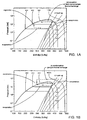
- air-conditioning systems of the type described above are generally configured to implement a sub-critical refrigerating cycle of the type illustrated in Figure 1A , i.e. a refrigerating cycle wherein the maximum pressure at which the refrigerating fluid is compressed and to which reference is generally made as condensation pressure, is always below the critical pressure p c characteristic of the refrigerating fluid itself.
- a sub-critical refrigerating cycle of the type illustrated in Figure 1A i.e. a refrigerating cycle wherein the maximum pressure at which the refrigerating fluid is compressed and to which reference is generally made as condensation pressure, is always below the critical pressure p c characteristic of the refrigerating fluid itself.
- condensation pressure p c
- the refrigerating fluid thereby yielding heat to the outside, i.e. a thermal exchange takes place between a condensing fluid (which shall be partly in the liquid state and partly in the vapour state) and a gas (generally air).
- Air-conditioning systems are further provided with a fan which is arranged downstream of the evaporator and is operated to push conditioned air into the passenger compartment of the motor vehicle, and a fan which is arranged in front of the condenser and is operated automatically to maintain the coolant pressure in the condenser (condensation pressure) at optimal values in all operating conditions. Operation of the condenser fan determines, in fact, an increase in the air flowrate impinging upon the condenser, thus determining a reduction of the condensation pressure.
- the condenser fan is operated both for reasons of safety, i.e., to prevent the coolant pressure in the condenser from reaching the tightness pressure of the pipes in the air-conditioning system in which the coolant flows, and to maintain an acceptable performance of the air-conditioning system.
- the switching-on, switching-off, and the rotation speed of the condenser fan are controlled via a pressure switch calibrated on a number of threshold values of the condensation pressure. When each of these threshold values is exceeded, the condenser fan is operated at a corresponding rotation speed. In the majority of air-conditioning systems of modern motor vehicles, the condenser fan is operated at two levels, so that when a lower threshold value is exceeded the condenser fan is driven at a lower rotation speed, whereas when a higher threshold value is exceeded the condenser fan is driven at a higher rotation speed.
- the pressure switch is increasingly more frequently replaced by a linear pressure sensor, whilst the condenser fan is controlled with PWM (Pulse width Modulation) techniques.
- PWM Pulse width Modulation
- US patent application No. 2007/0125106 describes instead an automotive air-conditioning system configured to implement a super-critical refrigerating cycle of the type illustrated with a dotted line in Figure 1B , i.e. a refrigerating cycle wherein the refrigerating fluid, having been compressed to a pressure greater than its critical pressure p c , does not condense and, along the high-pressure tract of the cycle, a thermal exchange between two gases occurs.
- a radiator i.e. a gas/gas heat exchanger
- the above-mentioned patent application teaches controlling, for the super-critical refrigerating cycle, the switching-on and the rotational speed of the radiator fan as a function of the difference ⁇ T between the refrigerant fluid temperature (T g ) leaving the radiator and the atmospheric temperature (T a ).
- the patent application cited above teaches controlling the switching-on and the rotational speed of the radiator fan as a function of the difference between the actual high pressure (P h ) as measured along the super-critical tract of the refrigerating cycle, and a target pressure (P sec ) which is, in turn, a function of atmospheric temperature T a .
- US 2006/086113 A1 discloses a method and system for controlling a cooling fan that cooperates with an air conditioning condenser in a vehicle.
- the disclosed embodiments include steps and corresponding implementations for determining a speed of the vehicle, determining a discharge pressure of the air conditioning condenser, determining an ambient temperature of air surrounding the vehicle and determining an outlet temperature of a vehicle air conditioning system.
- the cooling fan is operated in one or more desired fan speed modes corresponding to one or more respective discharge pressure ranges.
- the fan speed modes are a function of vehicle speed and one or more of ambient temperature, outlet temperature, and discharge pressure.
- Figure 2 shows an air-conditioning system, designated as a whole by 1, for a passenger compartment of a vehicle (not shown), in particular a road motor vehicle such as a car, a bus, etc.
- the air-conditioning system 1 comprises a closed-loop cooling circuit 3 and a heating circuit 4, which are connected to one another via a mixer 5 provided with a diffuser 6 that introduces the conditioned air into the passenger compartment of the motor vehicle through air vents appropriately arranged within the passenger compartment.
- the cooling circuit 3 is provided with an air-supply duct 7 having a first inlet 7a communicating with the outside of the motor vehicle, a second inlet 7b communicating with the passenger compartment of the motor vehicle, and an outlet 7c communicating with an inlet 8 of the mixer 5 through a duct 13.
- a selector 9 is arranged along the air-supply duct 7 for selectively connecting the outlet 7c with one or both of the inlets 7a, 7b. In this way, the air to be treated can be sucked selectively from the external environment and/or from the passenger compartment of the motor vehicle depending on the position of the selector 9.
- the cooling circuit 3 further comprises a compressor 14, a condenser 15, an evaporator 10, and a non-electronically-controlled expansion valve 16, in particular of the mechanical type, which are connected through a duct 11 in which a coolant, for example Freon, flows.
- a coolant for example Freon
- the compressor 14 is arranged in the engine compartment and is operated by the engine shaft of the internal-combustion engine of the motor vehicle via a belt;
- the condenser 15 is arranged on the front of the motor vehicle, in front of the radiator (not illustrated) so as to be impinged upon by the external air;
- the evaporator 10 is usually arranged also in the engine compartment behind the firewall that separates the engine compartment from the passenger compartment of the motor vehicle and is arranged in an area at the outlet 7c of the air-supply duct 7 so as to be impinged upon by the air coming from the inlets 7a, 7b.
- the compressor 14 has the task of compressing the coolant present in a vapour state at the evaporator outlet so as to increase its temperature and pressure.
- the coolant at the compressor outlet then flows through the condenser 15, where it yields heat to the air that traverses the condenser 15, so cooling and condensing, and hence passing from the gaseous state to the liquid state.
- the coolant then flows through the expansion valve 16, where it is cooled further and returns in part to the vapour phase.
- the coolant flows through the evaporator 10, where it absorbs heat from the air that traverses the evaporator 10, which air is cooled and is pushed into the mixer 5 via a fan 12, arranged along the duct 13 that connects the evaporator outlet with the mixer inlet 8. In this way, the coolant is heated, passing again to the vapour state, and is again supplied to the compressor 14, thus re-starting the cycle described above.
- the cooling circuit 3 further comprises a fan 17 arranged in front of the condenser 15 in such a way as to provide a forced air flow on the condenser 15, towards the inside of the motor vehicle, thus determining a reduction in the temperature and pressure of the coolant in the condenser 15.
- the mixer 5 defines an internal chamber 18, which communicates with the passenger compartment of the motor vehicle through the diffuser 6 and within which two paths 18h and 18c are defined, separate from one another and selectable by means of a selector 19 that supplies the air coming from the duct 13 to the paths 18h and 18c.
- the selector 19 can be positioned in a first limit position (indicated by the dashed line), where all the inlet air is supplied to the duct 18c, in a second limit position (not illustrated), where all the inlet air is supplied to the duct 18h, and in a plurality of intermediate positions, where the inlet air is partialized between the two ducts 18h and 18c.
- the duct 18h moreover communicates with an outlet of the heating circuit 4, which, as is known, is conveniently constituted by a liquid/air heat exchanger, which receives the internal-combustion engine coolant through a control solenoid valve not shown in figure 2 .
- the cold air coming from the evaporator 10, before being introduced into the passenger compartment of the motor vehicle through the diffuser 6, can be mixed with hot air coming from the heating circuit 4.
- the cold air flow F1 generated by the fan 12 can be appropriately mixed with the hot air flow F2 coming from the heating circuit 4 by means of the selector 19, which can be positioned either in such a way as to convey the entire cold air flow F1 towards the diffuser 6 (so-called "all cold” position), without enabling any passage of cold air in the hot-air duct and thus preventing mixing of hot and cold air, or in such a way as to enable completely (so-called "all hot” position), or just in part, passage of the cold air flow F1 in the hot-air duct, and thus favour mixing of the cold and hot air flows F1 and F2 based on a target temperature set by the motor vehicle occupants (via appropriate temperature setting means provided in the passenger compartment).
- the air-conditioning system 1 comprises an electronic control system 2, which in turn comprises, amongst other things:
- control software of the condenser fan stored in the electronic control unit 20 implements:
- the computation module 30 is configured to compute the target condensation pressure P target_fluid of the coolant in the condenser 15 according to a formula that is the result of an experimental bench-test campaign carried out by the Applicant in order to assess the influence of the use of the condenser fan 17 (in particular, of the air flowrate of the condenser fan 17) on the performance of the air-conditioning system 1 as the operating conditions of the air-conditioning system 1 vary.
- the Applicant has established that, by appropriately controlling, via an adequate use of the condenser fan 17, the coolant condensation pressure in the condenser 15 as a function of the external ambient temperature T ext, it is possible to reduce the work of the compressor 14 and of the condenser fan 17 significantly, thus enabling a reduction in the mechanical power absorbed by the air-conditioning system 1 from the internal-combustion engine, and thus sensibly improving the overall energy balance.
- the experimental bench-test campaign has made it possible to establish that for each external ambient temperature T ext there exists a target condensation pressure P target_fluid of the coolant in the condenser 15 that optimizes the absorption of energy by the compressor 14 and by the condenser fan 17.
- a non-electronically controlled expansion valve in an air-conditioning system implementing a sub-critical refrigerating cycle enables a significant reduction in the complexity of the software control of the condenser fan, and thereby a consequent reduction in the computational load of the electronic control unit of the air-conditioning system, an increase in the adaptability of the control of the condenser fan to the various operating conditions, and finally a reduction in the measurements necessary for providing said control.
- the various additive and multiplicative constants in Eq. (2), as well as the temperature range within which the target condensation pressure is computed based on Eq. (2) and the two substantially constant values assumed by the target condensation pressure outside of said temperature range could differ from the ones indicated.
Landscapes
- Physics & Mathematics (AREA)
- Thermal Sciences (AREA)
- Engineering & Computer Science (AREA)
- Mechanical Engineering (AREA)
- Air-Conditioning For Vehicles (AREA)
Abstract
Description
- The present invention relates to the control of a condenser fan of a automotive air-conditioning system.
- As it is known, motor vehicles are generally provided with air-conditioning systems of the type comprising, in succession, a compressor, a condenser, an expansion valve, and an evaporator, connected to one another via a duct through which a coolant, generally Freon, flows.
- As refrigerating fluids (or coolants) use is typically made of fluids such as ammonia, methyl chloride, sulphurous anhydride; halogenated hydrocarbons such as Freon (for example R11, R12, R114, R134a), or, further, substances like carbon dioxide and hydrocarbons like propane.
- In particular, air-conditioning systems of the type described above are generally configured to implement a sub-critical refrigerating cycle of the type illustrated in
Figure 1A , i.e. a refrigerating cycle wherein the maximum pressure at which the refrigerating fluid is compressed and to which reference is generally made as condensation pressure, is always below the critical pressure pc characteristic of the refrigerating fluid itself. Under those conditions, as a matter of fact, along the high-pressure tract of the cycle condensation of the refrigerating fluid occurs, the refrigerating fluid thereby yielding heat to the outside, i.e. a thermal exchange takes place between a condensing fluid (which shall be partly in the liquid state and partly in the vapour state) and a gas (generally air). Air-conditioning systems are further provided with a fan which is arranged downstream of the evaporator and is operated to push conditioned air into the passenger compartment of the motor vehicle, and a fan which is arranged in front of the condenser and is operated automatically to maintain the coolant pressure in the condenser (condensation pressure) at optimal values in all operating conditions. Operation of the condenser fan determines, in fact, an increase in the air flowrate impinging upon the condenser, thus determining a reduction of the condensation pressure. - The condenser fan is operated both for reasons of safety, i.e., to prevent the coolant pressure in the condenser from reaching the tightness pressure of the pipes in the air-conditioning system in which the coolant flows, and to maintain an acceptable performance of the air-conditioning system. A condensation pressure that is excessively high, in fact, causes a consequent increase in the coolant pressure in the evaporator and, hence, also of the conditioned air temperature at the evaporator outlet.
- Typically, the switching-on, switching-off, and the rotation speed of the condenser fan are controlled via a pressure switch calibrated on a number of threshold values of the condensation pressure. When each of these threshold values is exceeded, the condenser fan is operated at a corresponding rotation speed. In the majority of air-conditioning systems of modern motor vehicles, the condenser fan is operated at two levels, so that when a lower threshold value is exceeded the condenser fan is driven at a lower rotation speed, whereas when a higher threshold value is exceeded the condenser fan is driven at a higher rotation speed.
- In order to enable efficient energy management of the air-conditioning system, in more recent models of motor vehicles, the pressure switch is increasingly more frequently replaced by a linear pressure sensor, whilst the condenser fan is controlled with PWM (Pulse width Modulation) techniques.
- Such a control of the condenser fan entails, however, the disadvantage of not taking into account the impact that the use of the condenser fan has on the overall energy balance of the motor vehicle. As is known, in fact, the compressor behaves like a pump that operates between two pressure levels and, consequently, it may be readily appreciated how the more the coolant pressure at the evaporator output approaches the coolant pressure at the condenser inlet, the smaller the work that the compressor has to do to bring the coolant to the required pressure and, consequently, the smaller the mechanical power that the compressor absorbs from the internal combustion engine.
- In fact, even though operation of the condenser fan for reducing the condensation pressure results in a reduction of the work that the compressor has to perform to bring the coolant pressure to the required value, operation of the condenser fan results, on the other hand, in an increase in the electric power absorbed from the alternator, and, since the latter is also operated by the internal combustion engine via a belt, a consequent increase in the mechanical power absorbs from the internal combustion engine and hence in the fuel consumption.
-
US patent application No. 2007/0125106 describes instead an automotive air-conditioning system configured to implement a super-critical refrigerating cycle of the type illustrated with a dotted line inFigure 1B , i.e. a refrigerating cycle wherein the refrigerating fluid, having been compressed to a pressure greater than its critical pressure pc, does not condense and, along the high-pressure tract of the cycle, a thermal exchange between two gases occurs. As a consequence, differently from an air-conditioning system configured to implement a sub-critical refrigerating cycle, an air-conditioning system configured to implement a super-critical refrigerating cycle provides for the use of a radiator (i.e. a gas/gas heat exchanger) instead of a condenser.
In particular, the above-mentioned patent application teaches controlling, for the super-critical refrigerating cycle, the switching-on and the rotational speed of the radiator fan as a function of the difference ΔT between the refrigerant fluid temperature (Tg) leaving the radiator and the atmospheric temperature (Ta). Alternatively, still for the operation under super-critical conditions, the patent application cited above teaches controlling the switching-on and the rotational speed of the radiator fan as a function of the difference between the actual high pressure (Ph) as measured along the super-critical tract of the refrigerating cycle, and a target pressure (Psec) which is, in turn, a function of atmospheric temperature Ta.
For the condition wherein actual high pressure Ph is less than the critical pressure of the refrigerating fluid and the radiator operates as a condenser, the patent application referred to above teaches instead a radically different approach for controlling the switching-on and the rotational speed of the fan. In particular, for sub-critical operating conditions, there is suggested that condensation pressure Ph be not controlled, and that, at one time: - a) the super-cooling degree of the refrigerating fluid leaving the radiator be controlled and thereby kept within a predetermined range, by controlling the opening degree of an electronically controlled expansion valve, so as to enhance a coefficient of performance (COP) of the system; and
- b) the cooling capacity of the radiator be controlled by varying the fan speed in response to variations in the condensation pressure Ph.
-
US 2006/086113 A1 discloses a method and system for controlling a cooling fan that cooperates with an air conditioning condenser in a vehicle. The disclosed embodiments include steps and corresponding implementations for determining a speed of the vehicle, determining a discharge pressure of the air conditioning condenser, determining an ambient temperature of air surrounding the vehicle and determining an outlet temperature of a vehicle air conditioning system. The cooling fan is operated in one or more desired fan speed modes corresponding to one or more respective discharge pressure ranges. The fan speed modes are a function of vehicle speed and one or more of ambient temperature, outlet temperature, and discharge pressure. - It is an object of the present invention to provide an automotive air-conditioning system configured to implement a sub-critical refrigerating fluid, wherein the fan control involves a computational load for the electronic control unit significantly reduced with respect to that entailed by the fan control carried out according to the teachings of
US patent application 2007/0125106 described above, thus reducing at the same time the impact of the air-conditioning system ono the energy balance of the engine. - According to the present invention, there is therefore provided an automotive air-conditioning system, as defined in the appended claims.
- For a better understanding of the present invention, a preferred embodiment thereof is now described, purely by way of non-limiting example, with reference to the attached drawings, wherein:
-
Figures 1A and 1B illustrate pressure/enthalpy diagrams of a sub-critical refrigerating cycle and of a super-critical refrigerating cycle, respectively; -
Figure 2 shows a block diagram of a motor vehicle air-conditioning system configured to implement a sub-criticla refrigerating cycle; -
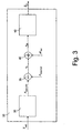
Figure 3 shows a block diagram of an electronic control system of the air-conditioning system ofFigure 2 ; and -
Figure 4 shows a plot of a target condensation pressure of a coolant flowing in a condenser of the air-conditioning system ofFigure 2 versus an ambient temperature outside of the motor vehicle. -
Figure 2 shows an air-conditioning system, designated as a whole by 1, for a passenger compartment of a vehicle (not shown), in particular a road motor vehicle such as a car, a bus, etc. - The air-conditioning system 1 comprises a closed-
loop cooling circuit 3 and a heating circuit 4, which are connected to one another via amixer 5 provided with a diffuser 6 that introduces the conditioned air into the passenger compartment of the motor vehicle through air vents appropriately arranged within the passenger compartment. - In particular, the
cooling circuit 3 is provided with an air-supply duct 7 having afirst inlet 7a communicating with the outside of the motor vehicle, asecond inlet 7b communicating with the passenger compartment of the motor vehicle, and anoutlet 7c communicating with aninlet 8 of themixer 5 through aduct 13. Aselector 9 is arranged along the air-supply duct 7 for selectively connecting theoutlet 7c with one or both of theinlets selector 9. - The
cooling circuit 3 further comprises acompressor 14, acondenser 15, anevaporator 10, and a non-electronically-controlledexpansion valve 16, in particular of the mechanical type, which are connected through aduct 11 in which a coolant, for example Freon, flows. - In general, the
compressor 14 is arranged in the engine compartment and is operated by the engine shaft of the internal-combustion engine of the motor vehicle via a belt; thecondenser 15 is arranged on the front of the motor vehicle, in front of the radiator (not illustrated) so as to be impinged upon by the external air; and theevaporator 10 is usually arranged also in the engine compartment behind the firewall that separates the engine compartment from the passenger compartment of the motor vehicle and is arranged in an area at theoutlet 7c of the air-supply duct 7 so as to be impinged upon by the air coming from theinlets - The
compressor 14 has the task of compressing the coolant present in a vapour state at the evaporator outlet so as to increase its temperature and pressure. The coolant at the compressor outlet then flows through thecondenser 15, where it yields heat to the air that traverses thecondenser 15, so cooling and condensing, and hence passing from the gaseous state to the liquid state. The coolant then flows through theexpansion valve 16, where it is cooled further and returns in part to the vapour phase. At this point, the coolant flows through theevaporator 10, where it absorbs heat from the air that traverses theevaporator 10, which air is cooled and is pushed into themixer 5 via a fan 12, arranged along theduct 13 that connects the evaporator outlet with themixer inlet 8. In this way, the coolant is heated, passing again to the vapour state, and is again supplied to thecompressor 14, thus re-starting the cycle described above. - The
cooling circuit 3 further comprises afan 17 arranged in front of thecondenser 15 in such a way as to provide a forced air flow on thecondenser 15, towards the inside of the motor vehicle, thus determining a reduction in the temperature and pressure of the coolant in thecondenser 15. - Once again with reference to
Figure 2 , themixer 5 defines aninternal chamber 18, which communicates with the passenger compartment of the motor vehicle through the diffuser 6 and within which twopaths selector 19 that supplies the air coming from theduct 13 to thepaths selector 19 can be positioned in a first limit position (indicated by the dashed line), where all the inlet air is supplied to theduct 18c, in a second limit position (not illustrated), where all the inlet air is supplied to theduct 18h, and in a plurality of intermediate positions, where the inlet air is partialized between the twoducts - The
duct 18h moreover communicates with an outlet of the heating circuit 4, which, as is known, is conveniently constituted by a liquid/air heat exchanger, which receives the internal-combustion engine coolant through a control solenoid valve not shown infigure 2 . - In the
mixer 5, the cold air coming from theevaporator 10, before being introduced into the passenger compartment of the motor vehicle through the diffuser 6, can be mixed with hot air coming from the heating circuit 4. In particular, the cold air flow F1 generated by the fan 12 can be appropriately mixed with the hot air flow F2 coming from the heating circuit 4 by means of theselector 19, which can be positioned either in such a way as to convey the entire cold air flow F1 towards the diffuser 6 (so-called "all cold" position), without enabling any passage of cold air in the hot-air duct and thus preventing mixing of hot and cold air, or in such a way as to enable completely (so-called "all hot" position), or just in part, passage of the cold air flow F1 in the hot-air duct, and thus favour mixing of the cold and hot air flows F1 and F2 based on a target temperature set by the motor vehicle occupants (via appropriate temperature setting means provided in the passenger compartment). - Finally, the air-conditioning system 1 comprises an electronic control system 2, which in turn comprises, amongst other things:
- a
temperature sensor 21, which may be conveniently, but not necessarily, arranged on a lower face of a rear-view mirror on the driver side (not illustrated), and supplies an electrical signal indicative of the ambient temperature Text outside the motor vehicle, hereinafter referred to, for reasons of brevity, as "external ambient temperature"; - a
pressure sensor 22 arranged at the condenser inlet and supplying an electrical signal indicative of a measured condensation pressure Pmeas_fluid of the coolant in thecondenser 15; and - an
electronic control unit 20 connected to thetemperature sensor 21 and to thepressure sensor 22, and into which a control software has been loaded and stored, which is able, when executed, to control operation (switching-on, switching-off, and rotation speed) of thecondenser fan 17 based on the signals from the aforesaid sensors in the way described in detail hereinafter with reference toFigure 3 , which shows a functional block diagram of the control software of the condenser fan stored in theelectronic control unit 20. - As is shown in
Figure 3 , when executed, the control software of the condenser fan stored in theelectronic control unit 20 implements: - a
computation module 30 receiving the external ambient temperature Text acquired by thetemperature sensor 21 and supplying a target condensation pressure Ptarget_fluid of the coolant in thecondenser 15, computed in the way described in detail hereinafter; - a
first subtractor module 35 receiving the target condensation pressure Ptarget_fluid and the measured condensation pressure Pmeas_fiuid of the coolant in thecondenser 15 supplied by thecomputation module 30 and, respectively, by thepressure sensor 22, and supplying a pressure error ep equal to the difference between the measured condensation pressure Pmeas_fluid and the target condensation pressure Ptarget_fluid; - a
second subtractor module 40 receiving the pressure error ep and a pressure disturbance ΔPfluid, and supplying a purged pressure error epd equal to the difference between the pressure error ep and the pressure disturbance ΔPfluid, wherein the pressure disturbance ΔPfluid is a quantity estimated experimentally and representing neglected phenomena, compensated for by the control module described hereinafter, which tend to change the measured condensation pressure Pmeas_fluid of the coolant, such as, for example, the motor vehicle speed or the ambient temperature in the passenger compartment of the motor vehicle set by occupants via appropriate setting elements of the air-conditioning system; and - a
control module 45 receiving the purged pressure error epd and supplying a PWM control signal Sc for thecondenser fan 17, generated based on a control law described in what follows. - In particular, the
computation module 30 is configured to compute the target condensation pressure Ptarget_fluid of the coolant in thecondenser 15 according to a formula that is the result of an experimental bench-test campaign carried out by the Applicant in order to assess the influence of the use of the condenser fan 17 (in particular, of the air flowrate of the condenser fan 17) on the performance of the air-conditioning system 1 as the operating conditions of the air-conditioning system 1 vary. - In particular, during the experimental bench-test campaign, the performance of the air-conditioning system 1 was assessed based on the following merit parameters:
- an air temperature Tevap downstream of the
evaporator 10; and - a performance coefficient COP of the air-conditioning system 1, computed according to the formula:

where:- WRSFR is a cooling capacity generated by the
evaporator 10; - WMECC is a mechanical power absorbed by the
compressor 14; - WELE_VENT is an electric power absorbed by the
condenser fan 17; and - WELE_EVAP is an electric power absorbed by the evaporator fan 12.
- WRSFR is a cooling capacity generated by the
- Based on these merit parameters, the Applicant has established that, by appropriately controlling, via an adequate use of the
condenser fan 17, the coolant condensation pressure in thecondenser 15 as a function of the external ambient temperature Text, it is possible to reduce the work of thecompressor 14 and of thecondenser fan 17 significantly, thus enabling a reduction in the mechanical power absorbed by the air-conditioning system 1 from the internal-combustion engine, and thus sensibly improving the overall energy balance. - In the specific case, the experimental bench-test campaign has made it possible to establish that for each external ambient temperature Text there exists a target condensation pressure Ptarget_fluid of the coolant in the
condenser 15 that optimizes the absorption of energy by thecompressor 14 and by thecondenser fan 17. - The optimal relation between the target condensation pressure Ptarget_fluid and the external ambient temperature Text is shown in
Figure 4 and is represented by a broken line with three stretches, comprising: - a first stretch where the target condensation pressure Ptarget_fluid is substantially constant at a value of approximately 8 bar for external ambient temperatures Text lower than 15°C;
- a second stretch linearly increasing according to the equation:

during which the target condensation pressure Ptarget_fluid increases substantially linearly from 8 bar to 20 bar when the external ambient temperature Text increases from 15°C to 35°C; and - a third stretch, where the target condensation pressure Ptarpet_fluid is substantially constant at a value of approximately 20 bar for external ambient temperatures Text higher than 35°C.
- Finally, in order to generate the control signal Sc for the
condenser fan 17, thecontrol module 45 implements a transfer function F(s) of the type:
which is nothing other than a frequency filter, the parameters of which can be obtained through a model-based design, an identification process via experimental tests, and a frequency analysis of the control loop. - From an examination of the characteristics of the present invention the advantages that it makes possible are evident.
- In particular, it is emphasized that the Applicant has experimentally verified how the relationship between the target condensation pressure and the external ambient temperature illustrated in
Figure 4 enables a reduction of the work of the compressor and of the electrical absorption of the condenser fan, consequently reducing the absorption of energy of the air-conditioning system 1 and its impact on the overall energy balance of the motor vehicle. - In addition, the use of a non-electronically controlled expansion valve in an air-conditioning system implementing a sub-critical refrigerating cycle enables a significant reduction in the complexity of the software control of the condenser fan, and thereby a consequent reduction in the computational load of the electronic control unit of the air-conditioning system, an increase in the adaptability of the control of the condenser fan to the various operating conditions, and finally a reduction in the measurements necessary for providing said control.
- Finally, it is clear that modifications and variations can be made to what has been described and illustrated herein, without thereby departing from the sphere of protection of the present invention, as defined in the annexed claims.
- For example, the various additive and multiplicative constants in Eq. (2), as well as the temperature range within which the target condensation pressure is computed based on Eq. (2) and the two substantially constant values assumed by the target condensation pressure outside of said temperature range could differ from the ones indicated.
Claims (14)
- An automotive air-conditioning system (1) configured to implement a sub-critical refrigerating cycle and comprising a condenser (15) and an associated fan (17), a compressor (14), an evaporator (10), a non-electronically controlled expansion valve (16), and an electronic control system (2) configured to:• receive a signal indicating an external ambient temperature (Text ) outside the vehicle;• receive a signal indicating a measured condensation pressure (Pmeas_fluid ) of a coolant in the condenser (15);• determine a target condensation pressure (Ptarget_fluid ) of the coolant in the condenser (15) based on the external ambient temperature (Text ); and• generate a control signal (Sc ) for the condenser fan (17) based on the measured condensation pressure (Pmeas_fluid ) and the target condensation pressure (Ptarget_fluid) of the coolant in the condenser (15).
- The automotive air-conditioning system (1) according to claim 1, wherein the electronic control system (2) is further configured to:• determine a pressure error (ep ) indicative of a difference between the measured condensation pressure (Pmeas_fluid ) and the target condensation pressure (Ptarget_fluid ) of the coolant in the condenser (15); and• generate the control signal (Sc ) for the condenser fan (17) based on the pressure error (ep ).
- The automotive air-conditioning system (1) according to claim 2, wherein the electronic control system (2) is further configured to:• purge the pressure error (ep ) from a pressure disturbance (ΔPfluid ) due to phenomena that tend to change the measured condensation pressure (Pmeas_fluid ), such as a vehicle speed or an ambient temperature inside the passenger compartment of the vehicle set by a user via appropriate setting elements of the air-conditioning system (1); and• generate the control signal (Sc ) for the condenser fan (17) based on the purged pressure error (epd ) so as to bring the measured condensation pressure (Pmeas_fluid ) to being substantially equal to the target condensation pressure (Ptarget_fluid ) of the coolant in the condenser (15).
- The automotive air-conditioning system (1) according to any one of the preceding claims, wherein the target condensation pressure (Ptarget_fluid ) has a first substantially constant value for external ambient temperatures (Text ) lower than a given lower ambient temperature, a second substantially constant value, different from the first substantially constant value, for external ambient temperatures (Text ) higher than a given upper ambient temperature, and values comprised between the first and second substantially constant values for external ambient temperatures (Text ) between the lower and upper ambient temperatures.
- The automotive air-conditioning system (1) according to claim 4, wherein the second substantially constant value is higher than the first substantially constant value.
- The automotive air-conditioning system (1) according to claim 5, wherein the target condensation pressure (Ptarget_fluid ) increases substantially linearly between the first and the second substantially constant values.
- The automotive air-conditioning system (1) according to claim 6, wherein for external ambient temperatures (Text ) between the lower and upper ambient temperatures, the target condensation pressure (Ptarget_fluid ) is determined based on the following formula:

were Text is the external ambient temperature outside the vehicle and Ptarget_fluid is the target condensation pressure. - The automotive air-conditioning system (1) according to claim 7, wherein k1 = 3/5, k2 = 15 and k3 = 8.
- The automotive air-conditioning system (1) according to any one of the preceding claims 4 to 8, wherein the lower ambient temperature is approximately 15°C and the upper ambient temperature is approximately 35°C.
- The automotive air-conditioning system (1) according to any one of the preceding claims 4 to 9, wherein the first substantially constant value is approximately 8 bar and the second substantially constant value is approximately 20 bar.
- The automotive air-conditioning system (1) according to any one of the preceding claims, wherein the electronic control system (2) comprises an electronic control unit (20) programmed to generate the control signal (Sc) for the condenser fan (17) as claimed in any one of the preceding claims.
- The automotive air-conditioning system (1) according to any one of the preceding claims, wherein the expansion valve (16) is of a mechanical type.
- A vehicle comprising an automotive air-conditioning system (1) according to any one of the preceding claims.
- The vehicle according to claim 13, wherein the vehicle is a motor vehicle.
Priority Applications (1)
| Application Number | Priority Date | Filing Date | Title |
|---|---|---|---|
| EP09742414A EP2285607B1 (en) | 2008-05-09 | 2009-03-26 | Control of a condenser fan of an automotive air-conditioning system |
Applications Claiming Priority (3)
| Application Number | Priority Date | Filing Date | Title |
|---|---|---|---|
| EP08425320A EP2123492A1 (en) | 2008-05-09 | 2008-05-09 | Control of a condenser fan of an air-conditioning system for a passenger compartment of a motor vehicle |
| EP09742414A EP2285607B1 (en) | 2008-05-09 | 2009-03-26 | Control of a condenser fan of an automotive air-conditioning system |
| PCT/IB2009/005130 WO2009136241A1 (en) | 2008-05-09 | 2009-03-26 | Control of a condenser fan of an automotive air-conditioning system |
Publications (2)
| Publication Number | Publication Date |
|---|---|
| EP2285607A1 EP2285607A1 (en) | 2011-02-23 |
| EP2285607B1 true EP2285607B1 (en) | 2011-10-26 |
Family
ID=39789593
Family Applications (2)
| Application Number | Title | Priority Date | Filing Date |
|---|---|---|---|
| EP08425320A Withdrawn EP2123492A1 (en) | 2008-05-09 | 2008-05-09 | Control of a condenser fan of an air-conditioning system for a passenger compartment of a motor vehicle |
| EP09742414A Not-in-force EP2285607B1 (en) | 2008-05-09 | 2009-03-26 | Control of a condenser fan of an automotive air-conditioning system |
Family Applications Before (1)
| Application Number | Title | Priority Date | Filing Date |
|---|---|---|---|
| EP08425320A Withdrawn EP2123492A1 (en) | 2008-05-09 | 2008-05-09 | Control of a condenser fan of an air-conditioning system for a passenger compartment of a motor vehicle |
Country Status (4)
| Country | Link |
|---|---|
| US (1) | US8682526B2 (en) |
| EP (2) | EP2123492A1 (en) |
| AT (1) | ATE530364T1 (en) |
| WO (1) | WO2009136241A1 (en) |
Families Citing this family (12)
| Publication number | Priority date | Publication date | Assignee | Title |
|---|---|---|---|---|
| US8209073B2 (en) * | 2009-05-06 | 2012-06-26 | Ford Global Technologies, Llc | Climate control system and method for optimizing energy consumption of a vehicle |
| CN102466304B (en) * | 2010-11-16 | 2014-09-03 | 力博特公司 | Air-conditioning system and control method of condensation fan thereof |
| FR2981887B1 (en) * | 2011-11-02 | 2015-04-17 | Renault Sas | STRUCTURAL AND MODULAR AIR GUIDE WITH TECHNICAL FRONT FACE FUNCTION OF MOTOR VEHICLE ENGINE AND VEHICLE SO EQUIPPED. |
| DE112013004959T5 (en) | 2012-10-10 | 2015-07-30 | Trane International Inc. | Variable fan speed control in HVAC systems and methods |
| DE102013213347A1 (en) * | 2013-07-08 | 2015-01-08 | Bayerische Motoren Werke Aktiengesellschaft | System for controlling a heating air conditioning in a motor vehicle |
| DE102014014032A1 (en) * | 2014-09-26 | 2016-03-31 | Martin Maul | Device for power generation, in particular ORC system |
| US9981637B2 (en) * | 2016-02-16 | 2018-05-29 | Alexander Kuo | Coolant measurement apparatus and method |
| US10850591B2 (en) | 2016-02-16 | 2020-12-01 | Pacific Link, L.L.C. | Apparatus and system for air conditioning output measurement and coolant servicing |
| DE102016204405A1 (en) | 2016-03-17 | 2017-09-21 | Martin Maul | Device for power generation, in particular ORC system |
| USD1047080S1 (en) | 2020-04-29 | 2024-10-15 | Ac Avalanche, Llc | Dispenser housing |
| MX2023005999A (en) | 2020-11-19 | 2023-07-31 | Pacific Link L L C | Autofill overfill protection temperature sensing air conditioning coolant recharge. |
| CN116811516B (en) * | 2023-03-21 | 2026-05-12 | 厦门大学嘉庚学院 | Intelligent control method for heat dissipation of air conditioner of new energy commercial bus |
Family Cites Families (12)
| Publication number | Priority date | Publication date | Assignee | Title |
|---|---|---|---|---|
| JPS6078823A (en) * | 1983-10-07 | 1985-05-04 | Nissan Motor Co Ltd | Air conditioner for vehicle |
| US5245836A (en) * | 1989-01-09 | 1993-09-21 | Sinvent As | Method and device for high side pressure regulation in transcritical vapor compression cycle |
| US5678410A (en) * | 1993-08-06 | 1997-10-21 | Toyota Jidosha Kabushiki Kaisha | Combined system of fuel cell and air-conditioning apparatus |
| JPH09196478A (en) * | 1996-01-23 | 1997-07-31 | Nippon Soken Inc | Refrigerating cycle |
| US6347528B1 (en) * | 1999-07-26 | 2002-02-19 | Denso Corporation | Refrigeration-cycle device |
| JP3985394B2 (en) * | 1999-07-30 | 2007-10-03 | 株式会社デンソー | Refrigeration cycle equipment |
| JP2005030363A (en) * | 2003-07-11 | 2005-02-03 | Denso Corp | Electric fan system for vehicles |
| US7275378B2 (en) * | 2004-10-21 | 2007-10-02 | Honda Motor Co., Ltd. | Speed and system pressure control for cooling fan |
| JP4758705B2 (en) * | 2005-08-05 | 2011-08-31 | サンデン株式会社 | Air conditioner for vehicles |
| JP2007139269A (en) * | 2005-11-16 | 2007-06-07 | Denso Corp | Supercritical refrigeration cycle |
| JP2008038833A (en) * | 2006-08-09 | 2008-02-21 | Calsonic Kansei Corp | Control device for variable displacement compressor and its method |
| JP2009008063A (en) * | 2007-06-29 | 2009-01-15 | Calsonic Kansei Corp | Control device of variable displacement compressor |
-
2008
- 2008-05-09 EP EP08425320A patent/EP2123492A1/en not_active Withdrawn
-
2009
- 2009-03-26 EP EP09742414A patent/EP2285607B1/en not_active Not-in-force
- 2009-03-26 WO PCT/IB2009/005130 patent/WO2009136241A1/en not_active Ceased
- 2009-03-26 AT AT09742414T patent/ATE530364T1/en not_active IP Right Cessation
- 2009-03-26 US US12/991,670 patent/US8682526B2/en not_active Expired - Fee Related
Also Published As
| Publication number | Publication date |
|---|---|
| US8682526B2 (en) | 2014-03-25 |
| ATE530364T1 (en) | 2011-11-15 |
| WO2009136241A1 (en) | 2009-11-12 |
| EP2123492A1 (en) | 2009-11-25 |
| EP2285607A1 (en) | 2011-02-23 |
| US20110137522A1 (en) | 2011-06-09 |
Similar Documents
| Publication | Publication Date | Title |
|---|---|---|
| US8682526B2 (en) | Control of a condenser fan of an automotive air-conditioning system | |
| US10946719B2 (en) | Vehicle air-conditioning device | |
| US11279205B2 (en) | Method for operating a coolant circuit and vehicle air-conditioning system | |
| US6047770A (en) | Air conditioning apparatus for vehicle | |
| US9873307B2 (en) | Vehicular air conditioner | |
| US7013659B2 (en) | Battery cooling system for vehicle | |
| US8688322B2 (en) | Air conditioner for vehicle | |
| JP4127230B2 (en) | Air conditioner for vehicles | |
| US10047988B2 (en) | Vehicle air conditioner | |
| EP2014491B1 (en) | Control apparatus for a vehicle air conditioner | |
| US20190210429A1 (en) | Vehicle air conditioner device | |
| US10252600B2 (en) | Air-conditioning apparatus for vehicle | |
| JP4003320B2 (en) | Refrigeration cycle equipment | |
| US20200324623A1 (en) | Vehicle Air Conditioning Device | |
| CN118632788A (en) | Vehicle air conditioning device | |
| US7562698B2 (en) | Vehicular air-conditioning system | |
| US20080229768A1 (en) | Air Conditioner for Vehicle | |
| JP2020075623A (en) | Vehicle air conditioner | |
| JP2001260635A (en) | Vehicle air conditioner | |
| JPH1142933A (en) | Air conditioner | |
| JP3404990B2 (en) | Heat pump type air conditioner for vehicles | |
| GB2395776A (en) | Vehicle air conditioner having a refrigerant cycle with heating function | |
| JPH1142934A (en) | Air conditioner | |
| JP3750291B2 (en) | Air conditioner for vehicles | |
| US12311737B2 (en) | Air conditioning device for vehicle |
Legal Events
| Date | Code | Title | Description |
|---|---|---|---|
| PUAI | Public reference made under article 153(3) epc to a published international application that has entered the european phase |
Free format text: ORIGINAL CODE: 0009012 |
|
| 17P | Request for examination filed |
Effective date: 20101108 |
|
| AK | Designated contracting states |
Kind code of ref document: A1 Designated state(s): AT BE BG CH CY CZ DE DK EE ES FI FR GB GR HR HU IE IS IT LI LT LU LV MC MK MT NL NO PL PT RO SE SI SK TR |
|
| AX | Request for extension of the european patent |
Extension state: AL BA RS |
|
| GRAP | Despatch of communication of intention to grant a patent |
Free format text: ORIGINAL CODE: EPIDOSNIGR1 |
|
| DAX | Request for extension of the european patent (deleted) | ||
| GRAS | Grant fee paid |
Free format text: ORIGINAL CODE: EPIDOSNIGR3 |
|
| GRAA | (expected) grant |
Free format text: ORIGINAL CODE: 0009210 |
|
| AK | Designated contracting states |
Kind code of ref document: B1 Designated state(s): AT BE BG CH CY CZ DE DK EE ES FI FR GB GR HR HU IE IS IT LI LT LU LV MC MK MT NL NO PL PT RO SE SI SK TR |
|
| REG | Reference to a national code |
Ref country code: GB Ref legal event code: FG4D |
|
| REG | Reference to a national code |
Ref country code: CH Ref legal event code: EP |
|
| REG | Reference to a national code |
Ref country code: IE Ref legal event code: FG4D |
|
| REG | Reference to a national code |
Ref country code: DE Ref legal event code: R096 Ref document number: 602009003352 Country of ref document: DE Effective date: 20111229 |
|
| REG | Reference to a national code |
Ref country code: NL Ref legal event code: VDEP Effective date: 20111026 |
|
| LTIE | Lt: invalidation of european patent or patent extension |
Effective date: 20111026 |
|
| REG | Reference to a national code |
Ref country code: AT Ref legal event code: MK05 Ref document number: 530364 Country of ref document: AT Kind code of ref document: T Effective date: 20111026 |
|
| PG25 | Lapsed in a contracting state [announced via postgrant information from national office to epo] |
Ref country code: IS Free format text: LAPSE BECAUSE OF FAILURE TO SUBMIT A TRANSLATION OF THE DESCRIPTION OR TO PAY THE FEE WITHIN THE PRESCRIBED TIME-LIMIT Effective date: 20120226 Ref country code: BE Free format text: LAPSE BECAUSE OF FAILURE TO SUBMIT A TRANSLATION OF THE DESCRIPTION OR TO PAY THE FEE WITHIN THE PRESCRIBED TIME-LIMIT Effective date: 20111026 Ref country code: LT Free format text: LAPSE BECAUSE OF FAILURE TO SUBMIT A TRANSLATION OF THE DESCRIPTION OR TO PAY THE FEE WITHIN THE PRESCRIBED TIME-LIMIT Effective date: 20111026 Ref country code: NO Free format text: LAPSE BECAUSE OF FAILURE TO SUBMIT A TRANSLATION OF THE DESCRIPTION OR TO PAY THE FEE WITHIN THE PRESCRIBED TIME-LIMIT Effective date: 20120126 |
|
| PG25 | Lapsed in a contracting state [announced via postgrant information from national office to epo] |
Ref country code: NL Free format text: LAPSE BECAUSE OF FAILURE TO SUBMIT A TRANSLATION OF THE DESCRIPTION OR TO PAY THE FEE WITHIN THE PRESCRIBED TIME-LIMIT Effective date: 20111026 Ref country code: SI Free format text: LAPSE BECAUSE OF FAILURE TO SUBMIT A TRANSLATION OF THE DESCRIPTION OR TO PAY THE FEE WITHIN THE PRESCRIBED TIME-LIMIT Effective date: 20111026 Ref country code: HR Free format text: LAPSE BECAUSE OF FAILURE TO SUBMIT A TRANSLATION OF THE DESCRIPTION OR TO PAY THE FEE WITHIN THE PRESCRIBED TIME-LIMIT Effective date: 20111026 Ref country code: SE Free format text: LAPSE BECAUSE OF FAILURE TO SUBMIT A TRANSLATION OF THE DESCRIPTION OR TO PAY THE FEE WITHIN THE PRESCRIBED TIME-LIMIT Effective date: 20111026 Ref country code: PT Free format text: LAPSE BECAUSE OF FAILURE TO SUBMIT A TRANSLATION OF THE DESCRIPTION OR TO PAY THE FEE WITHIN THE PRESCRIBED TIME-LIMIT Effective date: 20120227 Ref country code: PL Free format text: LAPSE BECAUSE OF FAILURE TO SUBMIT A TRANSLATION OF THE DESCRIPTION OR TO PAY THE FEE WITHIN THE PRESCRIBED TIME-LIMIT Effective date: 20111026 Ref country code: LV Free format text: LAPSE BECAUSE OF FAILURE TO SUBMIT A TRANSLATION OF THE DESCRIPTION OR TO PAY THE FEE WITHIN THE PRESCRIBED TIME-LIMIT Effective date: 20111026 Ref country code: GR Free format text: LAPSE BECAUSE OF FAILURE TO SUBMIT A TRANSLATION OF THE DESCRIPTION OR TO PAY THE FEE WITHIN THE PRESCRIBED TIME-LIMIT Effective date: 20120127 |
|
| PG25 | Lapsed in a contracting state [announced via postgrant information from national office to epo] |
Ref country code: CY Free format text: LAPSE BECAUSE OF FAILURE TO SUBMIT A TRANSLATION OF THE DESCRIPTION OR TO PAY THE FEE WITHIN THE PRESCRIBED TIME-LIMIT Effective date: 20111026 |
|
| PG25 | Lapsed in a contracting state [announced via postgrant information from national office to epo] |
Ref country code: SK Free format text: LAPSE BECAUSE OF FAILURE TO SUBMIT A TRANSLATION OF THE DESCRIPTION OR TO PAY THE FEE WITHIN THE PRESCRIBED TIME-LIMIT Effective date: 20111026 Ref country code: CZ Free format text: LAPSE BECAUSE OF FAILURE TO SUBMIT A TRANSLATION OF THE DESCRIPTION OR TO PAY THE FEE WITHIN THE PRESCRIBED TIME-LIMIT Effective date: 20111026 Ref country code: DK Free format text: LAPSE BECAUSE OF FAILURE TO SUBMIT A TRANSLATION OF THE DESCRIPTION OR TO PAY THE FEE WITHIN THE PRESCRIBED TIME-LIMIT Effective date: 20111026 Ref country code: EE Free format text: LAPSE BECAUSE OF FAILURE TO SUBMIT A TRANSLATION OF THE DESCRIPTION OR TO PAY THE FEE WITHIN THE PRESCRIBED TIME-LIMIT Effective date: 20111026 Ref country code: BG Free format text: LAPSE BECAUSE OF FAILURE TO SUBMIT A TRANSLATION OF THE DESCRIPTION OR TO PAY THE FEE WITHIN THE PRESCRIBED TIME-LIMIT Effective date: 20120126 |
|
| PG25 | Lapsed in a contracting state [announced via postgrant information from national office to epo] |
Ref country code: RO Free format text: LAPSE BECAUSE OF FAILURE TO SUBMIT A TRANSLATION OF THE DESCRIPTION OR TO PAY THE FEE WITHIN THE PRESCRIBED TIME-LIMIT Effective date: 20111026 |
|
| PLBE | No opposition filed within time limit |
Free format text: ORIGINAL CODE: 0009261 |
|
| STAA | Information on the status of an ep patent application or granted ep patent |
Free format text: STATUS: NO OPPOSITION FILED WITHIN TIME LIMIT |
|
| 26N | No opposition filed |
Effective date: 20120727 |
|
| PG25 | Lapsed in a contracting state [announced via postgrant information from national office to epo] |
Ref country code: MC Free format text: LAPSE BECAUSE OF NON-PAYMENT OF DUE FEES Effective date: 20120331 |
|
| REG | Reference to a national code |
Ref country code: DE Ref legal event code: R097 Ref document number: 602009003352 Country of ref document: DE Effective date: 20120727 |
|
| REG | Reference to a national code |
Ref country code: IE Ref legal event code: MM4A |
|
| PG25 | Lapsed in a contracting state [announced via postgrant information from national office to epo] |
Ref country code: IE Free format text: LAPSE BECAUSE OF NON-PAYMENT OF DUE FEES Effective date: 20120326 Ref country code: AT Free format text: LAPSE BECAUSE OF FAILURE TO SUBMIT A TRANSLATION OF THE DESCRIPTION OR TO PAY THE FEE WITHIN THE PRESCRIBED TIME-LIMIT Effective date: 20111026 |
|
| PG25 | Lapsed in a contracting state [announced via postgrant information from national office to epo] |
Ref country code: MK Free format text: LAPSE BECAUSE OF FAILURE TO SUBMIT A TRANSLATION OF THE DESCRIPTION OR TO PAY THE FEE WITHIN THE PRESCRIBED TIME-LIMIT Effective date: 20111026 |
|
| PG25 | Lapsed in a contracting state [announced via postgrant information from national office to epo] |
Ref country code: ES Free format text: LAPSE BECAUSE OF FAILURE TO SUBMIT A TRANSLATION OF THE DESCRIPTION OR TO PAY THE FEE WITHIN THE PRESCRIBED TIME-LIMIT Effective date: 20120206 |
|
| PG25 | Lapsed in a contracting state [announced via postgrant information from national office to epo] |
Ref country code: FI Free format text: LAPSE BECAUSE OF FAILURE TO SUBMIT A TRANSLATION OF THE DESCRIPTION OR TO PAY THE FEE WITHIN THE PRESCRIBED TIME-LIMIT Effective date: 20111026 |
|
| PG25 | Lapsed in a contracting state [announced via postgrant information from national office to epo] |
Ref country code: MT Free format text: LAPSE BECAUSE OF FAILURE TO SUBMIT A TRANSLATION OF THE DESCRIPTION OR TO PAY THE FEE WITHIN THE PRESCRIBED TIME-LIMIT Effective date: 20111026 |
|
| REG | Reference to a national code |
Ref country code: CH Ref legal event code: PL |
|
| GBPC | Gb: european patent ceased through non-payment of renewal fee |
Effective date: 20130326 |
|
| PG25 | Lapsed in a contracting state [announced via postgrant information from national office to epo] |
Ref country code: GB Free format text: LAPSE BECAUSE OF NON-PAYMENT OF DUE FEES Effective date: 20130326 Ref country code: CH Free format text: LAPSE BECAUSE OF NON-PAYMENT OF DUE FEES Effective date: 20130331 Ref country code: LI Free format text: LAPSE BECAUSE OF NON-PAYMENT OF DUE FEES Effective date: 20130331 |
|
| PG25 | Lapsed in a contracting state [announced via postgrant information from national office to epo] |
Ref country code: TR Free format text: LAPSE BECAUSE OF FAILURE TO SUBMIT A TRANSLATION OF THE DESCRIPTION OR TO PAY THE FEE WITHIN THE PRESCRIBED TIME-LIMIT Effective date: 20111026 |
|
| PG25 | Lapsed in a contracting state [announced via postgrant information from national office to epo] |
Ref country code: LU Free format text: LAPSE BECAUSE OF NON-PAYMENT OF DUE FEES Effective date: 20120326 |
|
| PGFP | Annual fee paid to national office [announced via postgrant information from national office to epo] |
Ref country code: IT Payment date: 20140320 Year of fee payment: 6 Ref country code: FR Payment date: 20140311 Year of fee payment: 6 |
|
| PG25 | Lapsed in a contracting state [announced via postgrant information from national office to epo] |
Ref country code: HU Free format text: LAPSE BECAUSE OF FAILURE TO SUBMIT A TRANSLATION OF THE DESCRIPTION OR TO PAY THE FEE WITHIN THE PRESCRIBED TIME-LIMIT Effective date: 20090326 |
|
| PGFP | Annual fee paid to national office [announced via postgrant information from national office to epo] |
Ref country code: DE Payment date: 20140417 Year of fee payment: 6 |
|
| REG | Reference to a national code |
Ref country code: DE Ref legal event code: R119 Ref document number: 602009003352 Country of ref document: DE |
|
| PG25 | Lapsed in a contracting state [announced via postgrant information from national office to epo] |
Ref country code: IT Free format text: LAPSE BECAUSE OF NON-PAYMENT OF DUE FEES Effective date: 20150326 |
|
| REG | Reference to a national code |
Ref country code: FR Ref legal event code: ST Effective date: 20151130 |
|
| PG25 | Lapsed in a contracting state [announced via postgrant information from national office to epo] |
Ref country code: DE Free format text: LAPSE BECAUSE OF NON-PAYMENT OF DUE FEES Effective date: 20151001 |
|
| PG25 | Lapsed in a contracting state [announced via postgrant information from national office to epo] |
Ref country code: FR Free format text: LAPSE BECAUSE OF NON-PAYMENT OF DUE FEES Effective date: 20150331 |