EP2285226B1 - Carcass cleaning device - Google Patents
Carcass cleaning device Download PDFInfo
- Publication number
- EP2285226B1 EP2285226B1 EP08748796.3A EP08748796A EP2285226B1 EP 2285226 B1 EP2285226 B1 EP 2285226B1 EP 08748796 A EP08748796 A EP 08748796A EP 2285226 B1 EP2285226 B1 EP 2285226B1
- Authority
- EP
- European Patent Office
- Prior art keywords
- suction
- steam
- carcass
- nozzle
- nozzle arrangement
- Prior art date
- Legal status (The legal status is an assumption and is not a legal conclusion. Google has not performed a legal analysis and makes no representation as to the accuracy of the status listed.)
- Not-in-force
Links
Images

Classifications
-
- A—HUMAN NECESSITIES
- A22—BUTCHERING; MEAT TREATMENT; PROCESSING POULTRY OR FISH
- A22B—SLAUGHTERING
- A22B5/00—Accessories for use during or after slaughtering
- A22B5/0082—Cleaning, washing or disinfecting carcasses
Definitions
- the present invention relates to a cleaning device for cleaning the surface of a carcass by contact, the cleaning device comprising a plurality of steam discharge jets and a suction nozzle. Further, the invention relates to a combined nozzle arrangement.
- the carcass in question is in particular a carcass of a slaughtered animal to be cleaned during processing in a slaughterhouse, or similar.
- a cleaning device for cleaning a surface of a carcass by contact comprising a plurality of steam discharge jets and a plurality of suction nozzles being adapted to following an uneven surface of the carcass is known.
- the object of the invention is to provide a cleaning device for cleaning a surface of a carcass by contact with less manual operation and with no or less need for assessing or judging the type, degree and/or extension of contamination prior to cleaning.
- the cleaning device comprises a plurality of steam discharge jets for discharging steam onto the surface of the carcass and a plurality of suction nozzles for drawing in impurities, steam and condensate from the surface, whereby the suction nozzles are adapted to following an uneven surface of the carcass.
- the size of the cleaning device - that is, the area of carcass surface covered by the device at any one time - may easily be adapted to the desired cleaning process by varying the number of steam discharge jets and suction nozzles.
- a particular advantage is that the invention facilitates automation of the procedure of cleaning, in particular because an automated cleaning device will not need to comprise features enabling assessment of the nature or the spatial extent of the contamination.
- the suction nozzles and/or steam discharge jets are adapted for following the surface of the carcass in various ways, and to deflect resiliently when pressed against or swept over the carcass surface.
- the suction nozzles will automatically adapt to an uneven carcass surface. This is important, as practically the entire surface of a carcass is more or less uneven. Very few surface parts of a carcass indeed may be satisfactorily approximated by surfaces which are regular in a mathematical sense.
- the suction nozzles opposite protruding parts of the carcass surface will deflect more than suction nozzles opposite retracted or hollow parts of the surface, and this will enable that the cleaning device may be pressed further against the carcass, until the suction nozzles opposite retracted or hollow parts of the surface will actually contact these parts of the surface.
- suction nozzles may come into proper contact with the carcass surface just by pressing the device against the carcass surface or sweeping it along the surface while maintaining surface contact, thus enabling thorough cleaning of the whole surface without the need for guiding the cleaning device along the carcass surface in a precise or delicate manner.
- the suction nozzles comprise additional openings or cut-outs for entry of ambient air arranged at or near a mouth of each suction nozzle.
- the nozzle when the mouth of a nozzle is pressed against a surface, the nozzle may become choked or blocked, so that no air will enter the nozzle even if ample suction is provided. When the nozzle is choked this way, the air stream into the nozzle may become so weak that it has not the required force or capacity to carry impurities away from the surface in an efficient manner.
- At least a carcass-contacting mouth portion of each suction nozzle is preferably made from a flexible material, preferably silicone rubber.
- the suction nozzles When the suction nozzles, or at least a mouth portion thereof, are made from a flexible material, they will become able to adapting to an uneven surface, such as the surface of a carcass to be cleaned, by deflecting or deforming. Hereby it is attained that all suction nozzles may touch the carcass surface at any one time, thus providing for efficient cleaning. If the suction nozzles do not have suitable flexibility, nozzles touching protruding parts of the carcass surface may lift the cleaning device so high that other nozzles are indeed lifted from retracted portions of the surface. In this case, the latter nozzles may not clean the corresponding parts of the surface in an efficient manner.
- Silicone rubber or silicone-based materials are found to provide excellent results for this purpose as they are relatively cheap, very suitable for use with foodstuffs, and highly flexible.
- the cleaning device has a plurality of such combined nozzle arrangements.
- the cleaning device may be adapted to cover a desired area of carcass surface, and cleaning devices having different area coverage and indeed different shapes may be manufactured for different cleaning purposes.
- a hand-held cleaning head may be made, covering a small area;
- an elongated cleaning head for a cleaning machine may be made for sweeping along a carcass surface in a direction transverse to its direction of extension;
- a curved cleaning head may be made, particularly adapted to cleaning a specific, curved part of a carcass.
- the invention in another aspect, relates to a combined nozzle arrangement for use in a cleaning device with the above mentioned characteristics, comprising at least one steam discharge jet and at least one suction nozzle.
- a combined nozzle arrangement for use in a cleaning device with the above mentioned characteristics comprising at least one steam discharge jet and at least one suction nozzle.
- the combined nozzle arrangement is adapted to deflect resiliently when subjected to a force in a direction substantially transversely to the direction of the suction nozzle, and/or to give way or compress resiliently when subjected to a force in or in parallel with the direction of the suction nozzle.
- At least the mouth of the suction nozzle is in the combined nozzle arrangement made from silicone rubber.
- the combined nozzle arrangement is adapted to deflect considerably more when subjected to a force in a first direction substantially transversely to the direction of the suction nozzle or suction nozzles than in a second direction substantially transverse to the direction of the suction nozzle or suction nozzles, transversely to said first direction.
- the combined nozzle arrangement comprises at least six steam discharge jets and one central suction nozzle.
- the combined nozzle arrangement constitutes a portion of hose with the suction nozzle arranged substantially centrally as the lumen of the hose and the steam discharge jet or jets arranged in a wall portion of the hose.
- the combined nozzle arrangement is made from a hose with a uniform cross section along its length, and that the suction nozzle and the steam discharge jet or jets are provided by cutting off the hose at a desired length.
- nozzle arrangements may be manufactured by simply cutting the hose described into suitable lengths.
- the suction nozzles may have additional openings or cut-outs arranged at or near the nozzle for entry of ambient air into that suction nozzle.
- the cut-outs may simply be cut in the end face of the length of hose. It may well be, however, that the nozzle arrangements are more advantageously made by injection moulding, whereby finished nozzle arrangements may be produced in one moulding process, including suction nozzles, steam jets, cut-outs, and possibly means for fixing the combined nozzle arrangement to the cleaning device.
- the mouths of the steam discharge jets open into an end-face of the combined nozzle arrangement, between said additional openings or cut-outs.
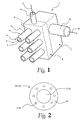
- FIG. 1 illustrates a relatively simple prototype of a cleaning device 1 according to the invention.
- the device 1 has the form of a box having a vacuum manifold 7, which may be connected to a vacuum source (not shown) via a vacuum connector 15 and a vacuum line (not shown). Arrow 19 indicates the direction of suction air flow.
- the device 1 further comprises a steam manifold 8 having a steam connector 6 for a steam line (not shown), for supply of steam from a steam source (not shown). Arrow 5 indicates the direction of steam flow.
- a base plate 9 of the device 1 carries six combined nozzle arrangements 14.
- the base plate 9 is constituted by a wall of the steam manifold 8.
- the combined nozzle arrangements 14 are made in the form of short lengths of hose 16 having a cross section as illustrated in Fig. 2 .
- the hose 16 thus has a wall 13 surrounding a hose lumen 17, and eight narrow, peripheral channels 4 extending in the wall 13 of the hose 16, in parallel with the lumen 17.
- each combined nozzle arrangement 14 has a free end or mouth 12, which is simply constituted by the distal end of the length of hose.
- the nozzle arrangement mouth 12 has one central suction nozzle 2, constituted by the distal end of the hose lumen 17, and eight peripheral steam discharge jets 3, constituted by the distal ends of the steam channels 4.
- Each central suction nozzle 2 (corresponding to the lumen 17 of the hose 16) is in communication with the vacuum manifold 7 via internal tubing (not shown) in the cleaning device body. All peripheral steam discharge jets 3 are in communication with the steam manifold 8.
- Steam from a steam supply line enters the steam manifold 8 via the steam connector 6 as indicated by arrow 5. From the steam manifold 8, the steam flows via the steam channels 4 and exits the steam discharge jets 3, which in the embodiment shown are constituted by the ends of the steam channels 4, at the mouth 12 of each nozzle arrangement 14.
- the steam pressure is controlled so that a desired steam flow (or pressure or temperature) is obtained out through the steam discharge jets 3.
- the steam may be superheated if a higher temperature is needed or desired.
- the steam pressure and the vacuum are adjusted such that steam escapes into the surroundings when the cleaning device 1 is not in contact with the carcass surface, whereas there is no visible escape of steam when the device is in abutment with the carcass.
- a vacuum line (not shown in Fig. 1 ) from a vacuum source is connected to the vacuum connector 15, which is via internal tubing (not shown) connected to each suction nozzle 2.
- the vacuum connector 15 is connected to the vacuum connector 15, which is via internal tubing (not shown) connected to each suction nozzle 2.
- ambient air is drawn into the suction nozzles 2 and via hose lumens 17, vacuum manifold 7 and vacuum line to an impurities collection tank or similar.
- the air draws excess steam, steam condensate and any impurities from the carcass surface into the suction nozzles 2 and further along to the impurities collection tank.
- the treated surface is left clean and in most cases even sterilised. Further, the treated surface is left substantially dry, or at least without any additional moisture from the cleaning process.
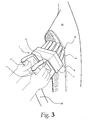
- the combined nozzle arrangements take the form of flexible 'fingers' which may deflect when they are held or pressed against the surface of a carcass body, as shown in Figs 3 and 8 .
- a hand-held prototype of the cleaning device 1 is shown in use during cleaning of the inside of a pig half-carcass 10.
- the cleaning device 1 is adapted for manual use by an operator in that it has two handles 11.
- the cleaning device has an array of 4 ⁇ 3 combined nozzle arrangements 14 or 'fingers', like the embodiment shown in Fig. 1 .
- Steam is supplied to the steam manifold 8 via a steam line (not shown) and further on to the steam discharge jets in the hose walls at the combined nozzle arrangement mouths 12.
- Vacuum is applied to the vacuum manifold 7 from a vacuum line 20 via a vacuum connector 15.
- Corresponding suction air is drawn into the suction nozzles 2 from the carcass surface environment at the mouths 12 of the combined nozzle arrangements 14.
- the cleaning device 1 is thus held with its combined nozzle arrangement mouths 12 against the carcass surface to be cleaned, and is preferably swept across the surface in order to subject a desired surface area to the cleaning treatment.
- the device 1 is pressed against the surface with suitable, but not excessive force so that the combined nozzle arrangements 14 or 'fingers' abutting high or raised areas of carcass surface are deformed or deflected to a certain degree as it appears from Fig. 3 . This will ensure that the fingers opposite retracted or hollow areas of carcass surface will be able to reach and abut these areas by not being deformed, or being deformed to a smaller degree.
- the cleaning device 1 works in a similar manner as a brush or a broom.
- the base plate 9 may be curved and/or sized to match desired parts of a carcass to be cleaned, for example convex for cleaning the inside of a carcass, such as at the pelvic region, or concave to match a convex outer surface of e.g. a ham.
- Hose-type steam discharge jets were tested in a prototype of the cleaning device of the invention.
- a hose 16 made by extrusion from a silicone rubber of VMQ-type sold as "Biosil 31399" by the company Asicomo was used for making the combined nozzle arrangements 14.
- This particular type of silicone rubber is transparent, peroxide-cured and food-contact approved, and has a standard-hardness of 60° ⁇ 5° Shore A.
- the hose 16 was circular in cross-section with an outer diameter of approximately 21 mm, and a central lumen 17 having an internal diameter of approximately 13 mm.
- eight peripheral steam channels 4 having an internal diameter of approximately 1.5 mm were provided in the wall of the hose. The steam channels 4 were spaced equally apart across the entire perimeter of the hose wall, as seen in cross section.
- the hose 16 was cut into lengths of approximately 70 mm, which were used as combined nozzle arrangements 14.
- the combined nozzle arrangements 14 were mounted on the base plate 9 of a cleaning device 1 in such a way that the lumen 17 of each hose was connected to the vacuum manifold 7 via internal tubing, and all steam channels 4 were connected to the steam manifold 8 in the cleaning device 1.
- Fig. 2 is a schematic view, not to scale, of the above-mentioned type of hose 16, and thus at the same time illustrating the structure of the embodiment of the combined nozzle arrangements just mentioned.
- This hose 16 has a lumen 17 surrounded by a hose wall 13, and eight peripheral steam channels 4 embedded into the hose wall.
- the corresponding, combined nozzle arrangement 14 comprises a central suction nozzle 2, constituted by the distal end of the length of hose and surrounded by the hose wall 13. Further, the combined nozzle arrangement 14 has in this embodiment eight steam discharge jets 3, constituted by the openings of the peripheral steam channels 4 where the hose 16 has been cut.
- This particular, circular embodiment of the nozzle arrangement 14 is only one possible form of nozzle arrangement.
- Particular cross-sectional shapes of combined nozzle arrangements may be advantageous for use in cleaning devices 1 for particular cleaning purposes. For example, if the cleaning device 1 is only to be swept across the carcass surface in one direction, it may be advantageous to provide the combined nozzle arrangements 14 with an oval or D-shaped cross section, in order that the flexibility of the nozzle arrangements may be increased in the direction in question while maintaining a maximum cross-sectional area of the suction nozzle 2.
- the mouth of the combined nozzle arrangements 14 may be cut off at a sloping angle rather than at right angles as shown in the drawing figures, for use for particular purposes.
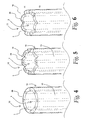
- the mouth of the combined nozzle arrangement 14 may be provided with openings or cut-outs 18 for entry of ambient air.
- Fig. 4 shows the distal portion of a combined nozzle arrangement 14 of the embodiment described above and shown in Figs 1-3 . It is evident that if the mouth 12 of this nozzle arrangement abuts a plane surface along its entire circumference, both the steam discharge jets 3 and the suction nozzle 2 may become blocked. Even if this situation may not happen very often during practical use, the consequences may be that a corresponding portion of carcass surface will not receive sufficient steam and will not have impurities, etc., removed to a satisfactory extent.
- the air flow into the suction nozzle 2 may be choked so much that it is insufficient to carry away the impurities, etc., collected from the carcass surface, and this may lead to re-contamination of cleaned areas of carcass surface.
- FIG. 5 eight V-shaped cut-outs 18 have been made in the end face 28 of the hose wall 13, in-between the steam discharge jets 3.
- air will enter from the carcass surface environment into the suction nozzle 2 via the cut-outs 18 and keep the air flow into the nozzle above a certain minimum level.
- Fig. 6 eight similar V-shaped cut-outs 18 have been made in the end face 28 of the hose wall 13, but coinciding with the steam discharge jets 3. That is, the steam discharge jets 3 open into the cut-outs 18. This will ensure that steam will always discharge from the steam discharge jets 3, irrespective of the abutment of the combined nozzle arrangement 14 on the carcass surface, and the air flow into the suction nozzle 2 is maintained in the same way as explained with reference to Fig. 5 .
- the flow resistance from the steam discharge jets 3 into the suction nozzle 2 is very small, and it is believed that this will tend to make the steam treatment less efficient because too much steam will escape from the steam discharge jets 3 directly into the suction nozzle 2 without reaching the carcass surface.
- Figs 2 and 4-6 it may according to the invention be advantageous to cut or chamfer the cut-outs 18 and/or the end face of the hose wall 13 in such a way that the steam discharged from the steam discharge jets 3 will meet less resistance when discharging into the space outside the hose wall 13 than when discharging into the lumen 17 of the hose, that is, into the suction nozzle 2.
- the vacuum in the suction nozzle 2 may tend to draw so much of the discharged steam into the suction nozzle 2 that only a too small fraction of the steam will eventually reach the carcass surface. If this situation arises, it may be advantageous to choke the flow path leading directly from the steam discharge jets 3 to the suction nozzle 2. This may be done by appropriate chamfering or cutting of the cut-outs 18, and the skilled person will be able to perform appropriate experiments for determining the details in this respect on the background of the explanations in the present disclosure.
- combined nozzle arrangements or 'fingers' 14 having a generally circular cross section like the ones shown Figs 1-6 may have a disadvantageous tendency to deflect sideways relative to the direction of sweep of the cleaning device 1 across the carcass surface. That is, if the cleaning device 1 is swept across a high (protruding) point of the carcass surface, the combined nozzle arrangements 14 or 'fingers' may tend to deflect sideways and thus move around the high point instead of over it. In this case, the high point of carcass surface may not be subjected to the desired degree of cleaning.
- fingers having oval or D-shaped cross section may be used.
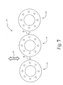
- the embodiment shown in Fig. 7 of a combined nozzle arrangement 21 may be used.
- a number of combined nozzle arrangements 14 of the type explained above and illustrated in Fig. 2 have been interconnected by means of flexible walls 22, thus forming the combined nozzle arrangement 21 having three suction nozzles 2 and 24 steam discharge jets 3.
- the combined nozzle arrangement 21 has an intended direction of sweep as indicated by arrow 23.
- the interconnections 22 will not influence the ability of the 'fingers' 14 to deflect in the direction 23 of sweep, while they will reduce very markedly the ability of the fingers 14 to deflect transversely to the direction 23 of sweep.
- the tendency of the fingers 14 of the combined nozzle arrangement 21 to deflect sideways around a protruding carcass surface part may be eliminated to a satisfactory degree.
- This configuration of the combined nozzle arrangement 21 will also lend itself well to being manufactured by extrusion.
- the interconnections 22 will however reduce the ability of each finger 14 of the combined nozzle arrangement 21 to deflect independently of the other fingers 14 of the combined nozzle arrangement 21 in the direction 23 of sweep.
- Test 1 Test 2 Combined nozzle arrangements ("fingers") Chamfered and serrated ends. Steam channels end at the bottom of the serrations. Diameter of steam channels approximately 1 mm. Straightly cut and serrated ends. Steam channels end at the bottom of the serrations. Diameter of steam channels approximately 1.5 mm. Steam pressure 1.0 Bar 1.5 Bar Suction vacuum Vacuum adjusted such that steam escapes into the surroundings when the device is not in contact with the carcass, whereas there is no escape of steam when the device is in abutment with the carcass.
- Vacuum adjusted such that steam escapes into the surroundings when the device is not in contact with the carcass, whereas there is no escape of steam when the device is in abutment with the carcass.
- Fig. 8 shows an experimental prototype of an automated cleaning machine for cleaning an outer surface portion of a pig half-carcass 10.
- two pig half-carcasses 10 are hanging from a gambrel (not shown).
- An experimental robot 24 having at least two directions 25 of linear movement is mounted near the station where the carcass is hanging, and a cleaning device 1 according to the invention has been mounted on the robot's arm 26.
- a steam supply line 27 and a vacuum line 20 have been connected to the cleaning device 1.
- the robot 24 is now able to sweep the cleaning device 1 across the outer surface of the near half-carcass 10 in at least the two directions 25, and a third direction may be added without any difficulty. Experiments have shown very satisfactory results from this prototype automated cleaning machine.
- the cleaning device 1 of the invention may be sized to cover the outer surface of a half-carcass, preferably in one dimension thereof for being swept or 'scanned' across the carcass half along another dimension. In that case the cleaning device may clean the outer surface of a complete carcass half by simply sweeping the cleaning device once along the outer surface of the carcass half.
- Suitable values for the flexibility or resiliency and length of the nozzle arrangements may depend on the particular use and they may be established without undue effort by the skilled person by experiment. The skilled person will realise that the flexibility of the nozzle should be chosen between the extremes of a very flexible and a very rigid embodiment.
- the very flexible embodiment increases the risk that the nozzles will deflect to a degree in which the cleaning and decontamination rendered by the steam discharge jet is ineffective as the mouth of the nozzle arrangement will disengages the surface to be cleaned, in particular at projecting parts of the surface.
- a very rigid embodiment increases the risk that the nozzles will not adapt to the surface to be cleaned, so that only projecting or non-concave portions of the surface will become in appropriate engagement with the nozzle arrangements.
Landscapes
- Life Sciences & Earth Sciences (AREA)
- Engineering & Computer Science (AREA)
- Food Science & Technology (AREA)
- Cleaning By Liquid Or Steam (AREA)
Description
- The present invention relates to a cleaning device for cleaning the surface of a carcass by contact, the cleaning device comprising a plurality of steam discharge jets and a suction nozzle. Further, the invention relates to a combined nozzle arrangement.
- The carcass in question is in particular a carcass of a slaughtered animal to be cleaned during processing in a slaughterhouse, or similar.
- In order to increase food safety, there is an increasing focus on minimising the risk of contamination of meat by e.g. bacteria. In recent years, a lot of effort and expenditure has been invested in reducing contamination of meat at slaughter-houses. Also, decontaminating or cleaning carcasses with steam to reduce visible contamination (e.g. dung) and non-visible contamination (e.g. bacteria) is being used to an increasing extent.
- State of the art for carcass cleaning and decontaminating includes the suction head described in
WO 03/026432 - From
WO 02/26045 - From
EP 0679335 a combined nozzle arrangement comprising one steam discharge jet and one suction nozzle being adapted to deflect resiliently when subjected to a force in a direction substantially transversely to the direction of the suction nozzle is known. - The object of the invention is to provide a cleaning device for cleaning a surface of a carcass by contact with less manual operation and with no or less need for assessing or judging the type, degree and/or extension of contamination prior to cleaning.
- To meet this object, the cleaning device according to the invention comprises a plurality of steam discharge jets for discharging steam onto the surface of the carcass and a plurality of suction nozzles for drawing in impurities, steam and condensate from the surface, whereby the suction nozzles are adapted to following an uneven surface of the carcass.
- Hereby corresponding advantages are obtained as stated with respect to the method of the invention.
- As the cleaning device comprises a plurality of steam discharge jets and a plurality of suction nozzles, the size of the cleaning device - that is, the area of carcass surface covered by the device at any one time - may easily be adapted to the desired cleaning process by varying the number of steam discharge jets and suction nozzles.
- A particular advantage is that the invention facilitates automation of the procedure of cleaning, in particular because an automated cleaning device will not need to comprise features enabling assessment of the nature or the spatial extent of the contamination.
- The suction nozzles and/or steam discharge jets are adapted for following the surface of the carcass in various ways, and to deflect resiliently when pressed against or swept over the carcass surface.
- By this measure, the suction nozzles will automatically adapt to an uneven carcass surface. This is important, as practically the entire surface of a carcass is more or less uneven. Very few surface parts of a carcass indeed may be satisfactorily approximated by surfaces which are regular in a mathematical sense.
- When the cleaning device is pressed against or swept over a carcass surface, the suction nozzles opposite protruding parts of the carcass surface will deflect more than suction nozzles opposite retracted or hollow parts of the surface, and this will enable that the cleaning device may be pressed further against the carcass, until the suction nozzles opposite retracted or hollow parts of the surface will actually contact these parts of the surface.
- It is hereby achieved that all suction nozzles may come into proper contact with the carcass surface just by pressing the device against the carcass surface or sweeping it along the surface while maintaining surface contact, thus enabling thorough cleaning of the whole surface without the need for guiding the cleaning device along the carcass surface in a precise or delicate manner.
- The suction nozzles comprise additional openings or cut-outs for entry of ambient air arranged at or near a mouth of each suction nozzle.
- In general, when the mouth of a nozzle is pressed against a surface, the nozzle may become choked or blocked, so that no air will enter the nozzle even if ample suction is provided. When the nozzle is choked this way, the air stream into the nozzle may become so weak that it has not the required force or capacity to carry impurities away from the surface in an efficient manner.
- When openings or cut-outs are provided, ambient air will be drawn in, providing for a sufficient air flow to carry impurities away from the carcass surface, even if the suction nozzle is abutting the carcass surface along its entire circumference.
- At least a carcass-contacting mouth portion of each suction nozzle is preferably made from a flexible material, preferably silicone rubber.
- When the suction nozzles, or at least a mouth portion thereof, are made from a flexible material, they will become able to adapting to an uneven surface, such as the surface of a carcass to be cleaned, by deflecting or deforming. Hereby it is attained that all suction nozzles may touch the carcass surface at any one time, thus providing for efficient cleaning. If the suction nozzles do not have suitable flexibility, nozzles touching protruding parts of the carcass surface may lift the cleaning device so high that other nozzles are indeed lifted from retracted portions of the surface. In this case, the latter nozzles may not clean the corresponding parts of the surface in an efficient manner.
- Silicone rubber or silicone-based materials are found to provide excellent results for this purpose as they are relatively cheap, very suitable for use with foodstuffs, and highly flexible.
- According to the invention it is preferred that a number of steam discharge jets and suction nozzles are integrated into a combined nozzle arrangement.
- Supply of steam onto the carcass surface is important, as the steam will at the same time loosen impurities and dissolve or disperse them into the steam flow and, by its very temperature, kill bacteria and micro-organisms.
- By providing steam discharge jets in the immediate vicinity of the suction nozzles when these are incorporated into a common or combined nozzle arrangement, an ample and efficient supply of steam is provided, and the steam is applied to the carcass surface where it is needed, that is, near each suction nozzle.
- In a preferred embodiment, the cleaning device has a plurality of such combined nozzle arrangements.
- Hereby, the cleaning device may be adapted to cover a desired area of carcass surface, and cleaning devices having different area coverage and indeed different shapes may be manufactured for different cleaning purposes. For instance, a hand-held cleaning head may be made, covering a small area; an elongated cleaning head for a cleaning machine may be made for sweeping along a carcass surface in a direction transverse to its direction of extension; and a curved cleaning head may be made, particularly adapted to cleaning a specific, curved part of a carcass.
- In another aspect, the invention relates to a combined nozzle arrangement for use in a cleaning device with the above mentioned characteristics, comprising at least one steam discharge jet and at least one suction nozzle. As mentioned above, it is advantageous to combine a number of steam discharge jets and suction nozzles into a combined nozzle arrangement for use in a cleaning device according to the invention.
- According to the invention, the combined nozzle arrangement is adapted to deflect resiliently when subjected to a force in a direction substantially transversely to the direction of the suction nozzle, and/or to give way or compress resiliently when subjected to a force in or in parallel with the direction of the suction nozzle.
- By these measures, similar advantages are attained as explained above with respect to the cleaning device of the invention.
- At least the mouth of the suction nozzle is in the combined nozzle arrangement made from silicone rubber.
- By these measures, similar advantages are attained as explained above with respect to the cleaning device of the invention.
- The combined nozzle arrangement is adapted to deflect considerably more when subjected to a force in a first direction substantially transversely to the direction of the suction nozzle or suction nozzles than in a second direction substantially transverse to the direction of the suction nozzle or suction nozzles, transversely to said first direction.
- This will eliminate or obviate a tendency of the combined nozzle arrangements to deflect sideways around a protrusion of the carcass surface when the cleaning device is swept over the carcass surface, instead of moving over the protrusion. In this way, it is ensured that the surface of the protrusion will be cleaned properly.
- The combined nozzle arrangement comprises at least six steam discharge jets and one central suction nozzle.
- It is preferred as well that the combined nozzle arrangement constitutes a portion of hose with the suction nozzle arranged substantially centrally as the lumen of the hose and the steam discharge jet or jets arranged in a wall portion of the hose.
- Further, it is preferred that the combined nozzle arrangement is made from a hose with a uniform cross section along its length, and that the suction nozzle and the steam discharge jet or jets are provided by cutting off the hose at a desired length.
- By these measures, a very simple and cost-efficient nozzle arrangement is obtained, as nozzle arrangements may be manufactured by simply cutting the hose described into suitable lengths.
- In a particular embodiment of the combined nozzle arrangement, the suction nozzles may have additional openings or cut-outs arranged at or near the nozzle for entry of ambient air into that suction nozzle.
- By this measure, similar advantages are attained as explained above with respect to the cleaning device of the invention.
- When the nozzle arrangements are made from lengths of a continuous hose, the cut-outs may simply be cut in the end face of the length of hose. It may well be, however, that the nozzle arrangements are more advantageously made by injection moulding, whereby finished nozzle arrangements may be produced in one moulding process, including suction nozzles, steam jets, cut-outs, and possibly means for fixing the combined nozzle arrangement to the cleaning device.
- In the particular embodiment mentioned, it is preferred that at least some of the mouths of the steam discharge jets open into an end-face of the combined nozzle arrangement, between said additional openings or cut-outs.
- This will provide for the steam discharge jet mouths coming in good contact with the carcass surface so that the steam will not easily escape into the suction nozzle or the surroundings, respectively, before it reaches the carcass surface. It is thus ensured that a sufficient steam supply to the surface is maintained.
- Preferred embodiments of the present invention will now be explained in more detail with reference to the drawings, in which:
-
Fig. 1 is a schematic drawing in perspective of a cleaning device according to the invention; -
Fig. 2 is a schematic cross-sectional view of a hose for the formation of a combined nozzle arrangement according to the invention; -
Fig. 3 is a schematic drawing of a prototype of a hand-held cleaning device according to the invention during use; -
Figs 4-6 are schematic drawings in perspective of mouth portions of combined nozzle arrangements according to the invention; -
Fig. 7 is a schematic cross-sectional view of a particular embodiment of a combined nozzle arrangement according to the invention; and -
Fig. 8 is a schematic drawing in perspective of an automated carcass cleaning machine comprising a cleaning device according to the invention. - The schematic drawing of
Fig. 1 illustrates a relatively simple prototype of acleaning device 1 according to the invention. Thedevice 1 has the form of a box having avacuum manifold 7, which may be connected to a vacuum source (not shown) via avacuum connector 15 and a vacuum line (not shown).Arrow 19 indicates the direction of suction air flow. Thedevice 1 further comprises a steam manifold 8 having asteam connector 6 for a steam line (not shown), for supply of steam from a steam source (not shown).Arrow 5 indicates the direction of steam flow. - A
base plate 9 of thedevice 1 carries six combinednozzle arrangements 14. In this embodiment, thebase plate 9 is constituted by a wall of the steam manifold 8. The combinednozzle arrangements 14 are made in the form of short lengths ofhose 16 having a cross section as illustrated inFig. 2 . Thehose 16 thus has awall 13 surrounding a hose lumen 17, and eight narrow,peripheral channels 4 extending in thewall 13 of thehose 16, in parallel with the lumen 17. - In
Fig. 1 , each combinednozzle arrangement 14 has a free end ormouth 12, which is simply constituted by the distal end of the length of hose. Thenozzle arrangement mouth 12 has onecentral suction nozzle 2, constituted by the distal end of the hose lumen 17, and eight peripheralsteam discharge jets 3, constituted by the distal ends of thesteam channels 4. - Each central suction nozzle 2 (corresponding to the lumen 17 of the hose 16) is in communication with the
vacuum manifold 7 via internal tubing (not shown) in the cleaning device body. All peripheralsteam discharge jets 3 are in communication with the steam manifold 8. - Steam from a steam supply line (not shown in
Fig. 1 ) enters the steam manifold 8 via thesteam connector 6 as indicated byarrow 5. From the steam manifold 8, the steam flows via thesteam channels 4 and exits thesteam discharge jets 3, which in the embodiment shown are constituted by the ends of thesteam channels 4, at themouth 12 of eachnozzle arrangement 14. The steam pressure is controlled so that a desired steam flow (or pressure or temperature) is obtained out through thesteam discharge jets 3. The steam may be superheated if a higher temperature is needed or desired. - At present, it is generally preferred that the steam pressure and the vacuum are adjusted such that steam escapes into the surroundings when the
cleaning device 1 is not in contact with the carcass surface, whereas there is no visible escape of steam when the device is in abutment with the carcass. - A vacuum line (not shown in
Fig. 1 ) from a vacuum source is connected to thevacuum connector 15, which is via internal tubing (not shown) connected to eachsuction nozzle 2. Thus, ambient air is drawn into thesuction nozzles 2 and via hose lumens 17,vacuum manifold 7 and vacuum line to an impurities collection tank or similar. The air draws excess steam, steam condensate and any impurities from the carcass surface into thesuction nozzles 2 and further along to the impurities collection tank. - The treated surface is left clean and in most cases even sterilised. Further, the treated surface is left substantially dry, or at least without any additional moisture from the cleaning process.
- As the
hose 16 is made from a flexible or highly flexible material such as silicone rubber, the combined nozzle arrangements take the form of flexible 'fingers' which may deflect when they are held or pressed against the surface of a carcass body, as shown inFigs 3 and8 . - Referring now to
Fig. 3 , a hand-held prototype of thecleaning device 1 is shown in use during cleaning of the inside of a pig half-carcass 10. In the embodiment shown inFig. 3 , thecleaning device 1 is adapted for manual use by an operator in that it has two handles 11. In this embodiment, the cleaning device has an array of 4 × 3 combinednozzle arrangements 14 or 'fingers', like the embodiment shown inFig. 1 . - Steam is supplied to the steam manifold 8 via a steam line (not shown) and further on to the steam discharge jets in the hose walls at the combined
nozzle arrangement mouths 12. - Vacuum is applied to the
vacuum manifold 7 from avacuum line 20 via avacuum connector 15. Corresponding suction air is drawn into thesuction nozzles 2 from the carcass surface environment at themouths 12 of the combinednozzle arrangements 14. - In the use shown in
Fig. 3 , thecleaning device 1 is thus held with its combinednozzle arrangement mouths 12 against the carcass surface to be cleaned, and is preferably swept across the surface in order to subject a desired surface area to the cleaning treatment. During sweeping, thedevice 1 is pressed against the surface with suitable, but not excessive force so that the combinednozzle arrangements 14 or 'fingers' abutting high or raised areas of carcass surface are deformed or deflected to a certain degree as it appears fromFig. 3 . This will ensure that the fingers opposite retracted or hollow areas of carcass surface will be able to reach and abut these areas by not being deformed, or being deformed to a smaller degree. - In this respect, the
cleaning device 1 works in a similar manner as a brush or a broom. - Steam escaping at a desired, suitable pressure and temperature from the
steam discharge jets 3 hits the carcass surface where it loosens and dissolves impurities, etc., and also sterilises the surface to a certain degree. The air entering thesuction nozzles 2 at a flow rate corresponding to i.a. the level of vacuum in thevacuum manifold 7, draws the loosened and/or dissolved impurities, etc., into thesuction nozzles 2, from where they are transported via thevacuum line 20 to an impurities collection tank or similar. Steam, condensate and any excess moisture is drawn in as well. - In this way, it is ensured that every portion of carcass surface swept over by the
nozzle arrangement mouths 12 will be thoroughly cleaned and disinfected. - Alternatively to a comparatively small, plane,
rectangular base plate 9 as in thecleaning devices 1 illustrated inFigs 1 and3 , thebase plate 9 may be curved and/or sized to match desired parts of a carcass to be cleaned, for example convex for cleaning the inside of a carcass, such as at the pelvic region, or concave to match a convex outer surface of e.g. a ham. - Hose-type steam discharge jets were tested in a prototype of the cleaning device of the invention. For the prototype, a
hose 16 made by extrusion from a silicone rubber of VMQ-type sold as "Biosil 31399" by the company Asicomo was used for making the combinednozzle arrangements 14. This particular type of silicone rubber is transparent, peroxide-cured and food-contact approved, and has a standard-hardness of 60° ± 5° Shore A. - The
hose 16 was circular in cross-section with an outer diameter of approximately 21 mm, and a central lumen 17 having an internal diameter of approximately 13 mm. In the wall of the hose, eightperipheral steam channels 4 having an internal diameter of approximately 1.5 mm were provided. Thesteam channels 4 were spaced equally apart across the entire perimeter of the hose wall, as seen in cross section. - The
hose 16 was cut into lengths of approximately 70 mm, which were used as combinednozzle arrangements 14. The combinednozzle arrangements 14 were mounted on thebase plate 9 of acleaning device 1 in such a way that the lumen 17 of each hose was connected to thevacuum manifold 7 via internal tubing, and allsteam channels 4 were connected to the steam manifold 8 in thecleaning device 1. -
Fig. 2 is a schematic view, not to scale, of the above-mentioned type ofhose 16, and thus at the same time illustrating the structure of the embodiment of the combined nozzle arrangements just mentioned. Thishose 16 has a lumen 17 surrounded by ahose wall 13, and eightperipheral steam channels 4 embedded into the hose wall. The corresponding, combinednozzle arrangement 14 comprises acentral suction nozzle 2, constituted by the distal end of the length of hose and surrounded by thehose wall 13. Further, the combinednozzle arrangement 14 has in this embodiment eightsteam discharge jets 3, constituted by the openings of theperipheral steam channels 4 where thehose 16 has been cut. - This particular, circular embodiment of the
nozzle arrangement 14 is only one possible form of nozzle arrangement. Particular cross-sectional shapes of combined nozzle arrangements may be advantageous for use incleaning devices 1 for particular cleaning purposes. For example, if thecleaning device 1 is only to be swept across the carcass surface in one direction, it may be advantageous to provide the combinednozzle arrangements 14 with an oval or D-shaped cross section, in order that the flexibility of the nozzle arrangements may be increased in the direction in question while maintaining a maximum cross-sectional area of thesuction nozzle 2. - In addition, the mouth of the combined
nozzle arrangements 14 may be cut off at a sloping angle rather than at right angles as shown in the drawing figures, for use for particular purposes. - With reference to
Figs 4 to 6 , the mouth of the combinednozzle arrangement 14 may be provided with openings or cut-outs 18 for entry of ambient air. -
Fig. 4 shows the distal portion of a combinednozzle arrangement 14 of the embodiment described above and shown inFigs 1-3 . It is evident that if themouth 12 of this nozzle arrangement abuts a plane surface along its entire circumference, both thesteam discharge jets 3 and thesuction nozzle 2 may become blocked. Even if this situation may not happen very often during practical use, the consequences may be that a corresponding portion of carcass surface will not receive sufficient steam and will not have impurities, etc., removed to a satisfactory extent. - In particular, the air flow into the
suction nozzle 2 may be choked so much that it is insufficient to carry away the impurities, etc., collected from the carcass surface, and this may lead to re-contamination of cleaned areas of carcass surface. - In
Fig. 5 , eight V-shaped cut-outs 18 have been made in theend face 28 of thehose wall 13, in-between thesteam discharge jets 3. During use, air will enter from the carcass surface environment into thesuction nozzle 2 via the cut-outs 18 and keep the air flow into the nozzle above a certain minimum level. In the embodiment inFig. 5 , there is still the risk of thesteam discharge jets 3 being choked if the combinednozzle arrangement 14 is brought into complete abutment with a plane carcass surface, and this may block thesteam discharge jets 3, depending on the steam pressure and the abutment force. - In
Fig. 6 , eight similar V-shaped cut-outs 18 have been made in theend face 28 of thehose wall 13, but coinciding with thesteam discharge jets 3. That is, thesteam discharge jets 3 open into the cut-outs 18. This will ensure that steam will always discharge from thesteam discharge jets 3, irrespective of the abutment of the combinednozzle arrangement 14 on the carcass surface, and the air flow into thesuction nozzle 2 is maintained in the same way as explained with reference toFig. 5 . - Experiments have however shown that the reduction in microbiological contamination is better using the combined
nozzle arrangement 14 inFig. 5 than the one inFig. 6 . This is believed to be due to the fact that inFig. 6 , thesteam discharge jets 3 open at a distance from the carcass surface so that the steam is not directed onto the carcass surface as efficiently as in the embodiment inFig. 5 . - Also, in the embodiment in
Fig. 6 , the flow resistance from thesteam discharge jets 3 into thesuction nozzle 2 is very small, and it is believed that this will tend to make the steam treatment less efficient because too much steam will escape from thesteam discharge jets 3 directly into thesuction nozzle 2 without reaching the carcass surface. - In all the embodiments of
Figs 2 and4-6 , it may according to the invention be advantageous to cut or chamfer the cut-outs 18 and/or the end face of thehose wall 13 in such a way that the steam discharged from thesteam discharge jets 3 will meet less resistance when discharging into the space outside thehose wall 13 than when discharging into the lumen 17 of the hose, that is, into thesuction nozzle 2. The vacuum in thesuction nozzle 2 may tend to draw so much of the discharged steam into thesuction nozzle 2 that only a too small fraction of the steam will eventually reach the carcass surface. If this situation arises, it may be advantageous to choke the flow path leading directly from thesteam discharge jets 3 to thesuction nozzle 2. This may be done by appropriate chamfering or cutting of the cut-outs 18, and the skilled person will be able to perform appropriate experiments for determining the details in this respect on the background of the explanations in the present disclosure. - Experiments have further shown that combined nozzle arrangements or 'fingers' 14 having a generally circular cross section like the ones shown
Figs 1-6 may have a disadvantageous tendency to deflect sideways relative to the direction of sweep of thecleaning device 1 across the carcass surface. That is, if thecleaning device 1 is swept across a high (protruding) point of the carcass surface, the combinednozzle arrangements 14 or 'fingers' may tend to deflect sideways and thus move around the high point instead of over it. In this case, the high point of carcass surface may not be subjected to the desired degree of cleaning. - In order to obviate this tendency of the fingers to deflect sideways, fingers having oval or D-shaped cross section may be used. Alternatively, the embodiment shown in
Fig. 7 of a combinednozzle arrangement 21 may be used. In the latter embodiment, a number of combinednozzle arrangements 14 of the type explained above and illustrated inFig. 2 have been interconnected by means offlexible walls 22, thus forming the combinednozzle arrangement 21 having threesuction nozzles steam discharge jets 3. The combinednozzle arrangement 21 has an intended direction of sweep as indicated byarrow 23. Theinterconnections 22 will not influence the ability of the 'fingers' 14 to deflect in thedirection 23 of sweep, while they will reduce very markedly the ability of thefingers 14 to deflect transversely to thedirection 23 of sweep. Hereby, the tendency of thefingers 14 of the combinednozzle arrangement 21 to deflect sideways around a protruding carcass surface part may be eliminated to a satisfactory degree. This configuration of the combinednozzle arrangement 21 will also lend itself well to being manufactured by extrusion. - The
interconnections 22 will however reduce the ability of eachfinger 14 of the combinednozzle arrangement 21 to deflect independently of theother fingers 14 of the combinednozzle arrangement 21 in thedirection 23 of sweep. - It is believed that a compromise between the disadvantages mentioned above may be achieved by varying the thickness of the
interconnections 22, by removing theinterconnections 22 from distal portions of thefingers 14 or by other variations of the mechanical characteristics of theinterconnections 22. - In general, good results have been achieved using saturated steam at a pressure of 1 to 2 bar, measured at the beginning of a flexible steam supply line (27), that is, one or two metres from the
cleaning device 1, and a suction vacuum of 0.2 to 0.3 bar, measured in the impurities collection tank, which may be connected to thecleaning device 1 via 10 to 15 metres of piping. - Two tests have been carried out with different configurations of the combined
nozzle arrangements 14 made from the hose having the cross section illustrated inFig. 2 , and with different operational variables, as outlined in the following table:Test 1Test 2Combined nozzle arrangements ("fingers") Chamfered and serrated ends. Steam channels end at the bottom of the serrations. Diameter of steam channels approximately 1 mm. Straightly cut and serrated ends. Steam channels end at the bottom of the serrations. Diameter of steam channels approximately 1.5 mm. Steam pressure 1.0 Bar 1.5 Bar Suction vacuum Vacuum adjusted such that steam escapes into the surroundings when the device is not in contact with the carcass, whereas there is no escape of steam when the device is in abutment with the carcass. Vacuum adjusted such that steam escapes into the surroundings when the device is not in contact with the carcass, whereas there is no escape of steam when the device is in abutment with the carcass. Estimated consumption of water and energy 5.1 l water/carcass 3.0 l water/carcass 3.9 kWh/carcass 2.2 kWh/carcass - Both tests showed good results in reduction of bacteria.
-
Fig. 8 shows an experimental prototype of an automated cleaning machine for cleaning an outer surface portion of a pig half-carcass 10. In the figure, two pig half-carcasses 10 are hanging from a gambrel (not shown). Anexperimental robot 24 having at least twodirections 25 of linear movement is mounted near the station where the carcass is hanging, and acleaning device 1 according to the invention has been mounted on the robot'sarm 26. Asteam supply line 27 and avacuum line 20 have been connected to thecleaning device 1. - The
robot 24 is now able to sweep thecleaning device 1 across the outer surface of the near half-carcass 10 in at least the twodirections 25, and a third direction may be added without any difficulty. Experiments have shown very satisfactory results from this prototype automated cleaning machine. - Although the illustrated and described embodiments of the
cleaning device 1 of the invention are all relatively small, the skilled person will understand from the present disclosure that the size and shape of the cleaning device may be varied according to various needs. For example, the cleaning device may be sized to cover the outer surface of a half-carcass, preferably in one dimension thereof for being swept or 'scanned' across the carcass half along another dimension. In that case the cleaning device may clean the outer surface of a complete carcass half by simply sweeping the cleaning device once along the outer surface of the carcass half. - Suitable values for the flexibility or resiliency and length of the nozzle arrangements may depend on the particular use and they may be established without undue effort by the skilled person by experiment. The skilled person will realise that the flexibility of the nozzle should be chosen between the extremes of a very flexible and a very rigid embodiment.
- The very flexible embodiment increases the risk that the nozzles will deflect to a degree in which the cleaning and decontamination rendered by the steam discharge jet is ineffective as the mouth of the nozzle arrangement will disengages the surface to be cleaned, in particular at projecting parts of the surface. On the other hand, a very rigid embodiment increases the risk that the nozzles will not adapt to the surface to be cleaned, so that only projecting or non-concave portions of the surface will become in appropriate engagement with the nozzle arrangements.
- It will further be possible for the skilled person to vary the size, number and distribution of nozzle arrangements to provide the best results for any particular application of the cleaning device of the present invention.
-
- 1
- cleaning device
- 2
- suction nozzle
- 3
- steam discharge jet
- 4
- peripheral steam channel
- 5
- steam flow direction
- 6
- steam connector
- 7
- vacuum manifold
- 8
- steam manifold
- 9
- base plate
- 10
- carcass
- 11
- handle
- 12
- mouth of combined nozzle arrangement
- 13
- hose wall
- 14
- combined nozzle arrangement
- 15
- vacuum connector
- 16
- hose
- 17
- hose lumen
- 18
- cut-out
- 19
- suction air flow direction
- 20
- vacuum line
- 21
- combined nozzle arrangement
- 22
- flexible wall
- 23
- direction of sweep
- 24
- robot
- 25
- directions of movement
- 26
- robot arm
- 27
- steam supply line
- 28
- hose wall end face
Claims (9)
- A cleaning device (1) for cleaning a surface of a carcass by contact, the cleaning device (1) comprising a plurality of steam discharge jets (3) for discharging steam onto said surface and a plurality of suction nozzles (2) for drawing in impurities, steam and condensate from the surface, the suction nozzles being adapted to following an uneven surface of the carcass (10) and
at least some of the suction nozzles (2) are adapted to deflect resiliently when pressed against or swept across said carcass surface characterised in that
at least some of the suction nozzles (2) comprise additional openings or cut-outs (18) for entry of ambient air arranged at or near a mouth of the suction nozzle (2). - A cleaning device (1) according to claim 1, wherein at least a carcass-contacting mouth portion of at least some of the suction nozzles (2) is made from a flexible material, preferably silicone rubber.
- A cleaning device (1) according to any of claims 1 to 2, wherein a number of steam discharge jets (3) and suction nozzles (2) are integrated into a combined nozzle arrangement (14).
- A cleaning device (1) according to claim 3, comprising a plurality of said combined nozzle arrangements (14).
- A combined nozzle arrangement for use in a cleaning device according to claim 3 or 4, the nozzle arrangement (14) comprising at least one steam discharge jet (3) and at least one suction nozzle (2), the combined nozzle arrangement (14) being adapted to deflect resiliently when subjected to a force in a direction substantially transversely to the direction of the suction nozzle (2) or suction nozzles (2)
the combined nozzle arrangement (14) further being adapted to give way or compress resiliently when subjected to a force in or in parallel with the direction of the suction nozzle (2) or suction nozzles (2) characterised in that
the mouth of the suction nozzle (2) or suction nozzles (2) is made from silicone rubber,
being adapted to deflect considerably more when subjected to a force in a first direction substantially transversely to the direction of the suction nozzle (2) or suction nozzles (2) than in a second direction substantially transversely to the direction of the suction nozzle (2) or suction nozzles (2), transverse to said first direction where the nozzle arrangement (14) comprises one central suction nozzle (2) and at least six steam discharge jets (3). - A combined nozzle arrangement (14) according to claim 5, wherein the combined nozzle arrangement (14) constitutes a portion of hose (16) with the suction nozzle (2) arranged substantially centrally as the lumen of the hose (17) and the steam discharge jet (3) or jets (3) arranged in a wall portion of the hose (16).
- A combined nozzle arrangement (14) according to claim 6, wherein the combined nozzle arrangement (14) is made from a hose (16) with a uniform cross section along its length, and where the suction nozzle (2) and the steam discharge jet (3) or jets (3) are provided by cutting off the hose (16) at a desired length.
- A combined nozzle arrangement (14) according to any of claims 5 to 7, wherein at least some of the suction nozzles (2) have additional openings or cut-outs (18) arranged at or near the suction nozzle (2) for entry of ambient air into that suction nozzle (2).
- A combined nozzle arrangement (14) according to claim 8, wherein at least some of the mouths of the steam discharge jets (2) open into an end-face of the combined nozzle arrangement (14), between said additional openings or cut-outs (18).
Applications Claiming Priority (1)
| Application Number | Priority Date | Filing Date | Title |
|---|---|---|---|
| PCT/DK2008/000185 WO2009138083A1 (en) | 2008-05-16 | 2008-05-16 | Carcass cleaning method, device and machine |
Publications (3)
| Publication Number | Publication Date |
|---|---|
| EP2285226A1 EP2285226A1 (en) | 2011-02-23 |
| EP2285226A4 EP2285226A4 (en) | 2012-08-08 |
| EP2285226B1 true EP2285226B1 (en) | 2014-07-23 |
Family
ID=41318376
Family Applications (1)
| Application Number | Title | Priority Date | Filing Date |
|---|---|---|---|
| EP08748796.3A Not-in-force EP2285226B1 (en) | 2008-05-16 | 2008-05-16 | Carcass cleaning device |
Country Status (6)
| Country | Link |
|---|---|
| US (1) | US20110165827A1 (en) |
| EP (1) | EP2285226B1 (en) |
| AU (1) | AU2008356457A1 (en) |
| CA (1) | CA2726547A1 (en) |
| DK (1) | DK2285226T3 (en) |
| WO (1) | WO2009138083A1 (en) |
Cited By (1)
| Publication number | Priority date | Publication date | Assignee | Title |
|---|---|---|---|---|
| CN109329356A (en) * | 2018-11-29 | 2019-02-15 | 周俊杰 | A kind of pig slaughtering and cleaning process |
Families Citing this family (4)
| Publication number | Priority date | Publication date | Assignee | Title |
|---|---|---|---|---|
| EP2339921B1 (en) | 2008-08-22 | 2015-07-15 | Force Technology | Method for cleaning and/or disinfecting a food product |
| DK180343B1 (en) | 2018-11-26 | 2021-01-15 | Teknologisk Inst | System and method for automatic removal of foreign objects from a food surface |
| DK180441B1 (en) * | 2019-09-02 | 2021-04-23 | Teknologisk Inst | Automatic removal of contamination on carcasses |
| WO2022094249A1 (en) * | 2020-10-30 | 2022-05-05 | Magic Sports, Llc | Bat swing training device |
Family Cites Families (15)
| Publication number | Priority date | Publication date | Assignee | Title |
|---|---|---|---|---|
| US2305232A (en) * | 1940-09-05 | 1942-12-15 | Seth S Barker | Apparatus for defeathering fowls |
| US3186132A (en) * | 1963-09-16 | 1965-06-01 | Zero Mfg Company | Surface treating apparatus and method |
| US4074387A (en) * | 1976-12-27 | 1978-02-21 | Centaur Floor Machines Ltd. | Vacuum cleaner attachment |
| US5503594A (en) * | 1995-01-25 | 1996-04-02 | Kentmaster Mfg. Co., Inc. | Carccass cleaning system |
| NZ270963A (en) * | 1994-04-28 | 1997-11-24 | Kentmaster Mfg Co Inc | Carcass cleaning system; manually positionable vacuum head simultaneously sprays cleaning fluid onto carcass surface and vacuums away liquid and contamination |
| US5607349A (en) * | 1994-04-28 | 1997-03-04 | Kentmaster Mfg. Co., Inc. | Carcass cleaning system |
| US5908375A (en) * | 1994-07-22 | 1999-06-01 | Ranpak Corp. | Manual feed cushioning machine and method |
| CN1171724A (en) * | 1994-11-07 | 1998-01-28 | 弗里高斯堪蒂亚有限公司 | Method and apparatus for pasteurizing meat |
| NL1000376C2 (en) * | 1995-05-17 | 1996-11-19 | Stork Rms Bv | Device for treating a slaughtered animal or part thereof. |
| US5632670A (en) * | 1995-10-26 | 1997-05-27 | Jarvis Products Corporation | Vacuum steam wand for sanitizing a carcass |
| US5928074A (en) * | 1997-12-23 | 1999-07-27 | Schrader; Melissa A. | Method for removing oral cavity staining, method for processing hogs, apparatus for delivering stain removing solution, and method for reducing bacteria level in a hog carcass oral cavity |
| US6243914B1 (en) * | 1999-08-04 | 2001-06-12 | Hydramaster Corporation | Sprayless surface cleaner |
| GB0023980D0 (en) * | 2000-09-29 | 2000-11-15 | Food Pro Systems Ltd | Carcass cleaning devices and methods |
| DK174937B1 (en) * | 2001-09-26 | 2004-03-08 | Slagteriernes Forskningsinst | Suction head for cleaning the surface of carcass parts |
| GB2398617A (en) * | 2003-02-20 | 2004-08-25 | Chung-Cheng Wu | Multi-path hose |
-
2008
- 2008-05-16 DK DK08748796.3T patent/DK2285226T3/en active
- 2008-05-16 AU AU2008356457A patent/AU2008356457A1/en not_active Abandoned
- 2008-05-16 US US12/995,099 patent/US20110165827A1/en not_active Abandoned
- 2008-05-16 CA CA2726547A patent/CA2726547A1/en not_active Abandoned
- 2008-05-16 WO PCT/DK2008/000185 patent/WO2009138083A1/en not_active Ceased
- 2008-05-16 EP EP08748796.3A patent/EP2285226B1/en not_active Not-in-force
Cited By (2)
| Publication number | Priority date | Publication date | Assignee | Title |
|---|---|---|---|---|
| CN109329356A (en) * | 2018-11-29 | 2019-02-15 | 周俊杰 | A kind of pig slaughtering and cleaning process |
| CN109329356B (en) * | 2018-11-29 | 2020-12-18 | 江苏天之邦食品有限公司 | A process for slaughtering and cleaning live pigs |
Also Published As
| Publication number | Publication date |
|---|---|
| AU2008356457A1 (en) | 2009-11-19 |
| EP2285226A1 (en) | 2011-02-23 |
| EP2285226A4 (en) | 2012-08-08 |
| WO2009138083A1 (en) | 2009-11-19 |
| US20110165827A1 (en) | 2011-07-07 |
| DK2285226T3 (en) | 2014-10-13 |
| CA2726547A1 (en) | 2009-11-19 |
Similar Documents
| Publication | Publication Date | Title |
|---|---|---|
| US5607349A (en) | Carcass cleaning system | |
| US20110165827A1 (en) | Carcass Cleaning Method, Device and Machine | |
| US5503594A (en) | Carccass cleaning system | |
| US3574885A (en) | Pet brush | |
| JP6444116B2 (en) | Kitchen knife drying sterilizer | |
| KR20190080220A (en) | Apparatus for automatic sterilizing of ultrasonic probe | |
| EP0679335B1 (en) | Carcass cleaning system | |
| KR101956853B1 (en) | Fur nishing Removal system | |
| CA2553324C (en) | Device and method for cleaning the abdominal cavity in fish | |
| CN118697064B (en) | Integrated cleaning equipment for food processing | |
| US20070174985A1 (en) | Toothbrush with tongue scraper/cleaner | |
| AU2001258600A1 (en) | Carcass cleaning devices and methods | |
| KR20100106265A (en) | Cleaning sterilizer for chopping board using rotation | |
| KR101908726B1 (en) | Cleaner for cattle shed using air jet | |
| EP1432318B1 (en) | Suction head for cleaning of the surface of carcass parts | |
| CA2552778A1 (en) | Apparatus and method for processing fur | |
| KR102063719B1 (en) | Sterilizing and drying apparatus for mat of vehicle floor | |
| IE20130291A1 (en) | Apparatus for sterilising a knife | |
| KR20150012553A (en) | egg drying apparatus | |
| CN208181963U (en) | A kind of sterilizing unit of plastic bottle closure | |
| PL4274459T3 (en) | Cleaner head and wet cleaning apparatus comprising the same | |
| KR200388856Y1 (en) | a box washer | |
| CN208676226U (en) | A kind of bone sawing machine with internal washing and stereo sterilization function | |
| CN112641115A (en) | Belt cleaning device is used in agricultural product processing | |
| KR20150114209A (en) | Apparatus for washing small intestine of cow |
Legal Events
| Date | Code | Title | Description |
|---|---|---|---|
| PUAI | Public reference made under article 153(3) epc to a published international application that has entered the european phase |
Free format text: ORIGINAL CODE: 0009012 |
|
| 17P | Request for examination filed |
Effective date: 20101201 |
|
| AK | Designated contracting states |
Kind code of ref document: A1 Designated state(s): AT BE BG CH CY CZ DE DK EE ES FI FR GB GR HR HU IE IS IT LI LT LU LV MC MT NL NO PL PT RO SE SI SK TR |
|
| AX | Request for extension of the european patent |
Extension state: AL BA MK RS |
|
| RAP1 | Party data changed (applicant data changed or rights of an application transferred) |
Owner name: TEKNOLOGISK INSTITUT |
|
| DAX | Request for extension of the european patent (deleted) | ||
| A4 | Supplementary search report drawn up and despatched |
Effective date: 20120709 |
|
| RIC1 | Information provided on ipc code assigned before grant |
Ipc: A22B 5/08 20060101ALI20120703BHEP Ipc: A22B 5/00 20060101AFI20120703BHEP Ipc: A22B 5/10 20060101ALI20120703BHEP Ipc: B08B 3/02 20060101ALI20120703BHEP |
|
| GRAP | Despatch of communication of intention to grant a patent |
Free format text: ORIGINAL CODE: EPIDOSNIGR1 |
|
| INTG | Intention to grant announced |
Effective date: 20140210 |
|
| GRAS | Grant fee paid |
Free format text: ORIGINAL CODE: EPIDOSNIGR3 |
|
| GRAA | (expected) grant |
Free format text: ORIGINAL CODE: 0009210 |
|
| AK | Designated contracting states |
Kind code of ref document: B1 Designated state(s): AT BE BG CH CY CZ DE DK EE ES FI FR GB GR HR HU IE IS IT LI LT LU LV MC MT NL NO PL PT RO SE SI SK TR |
|
| REG | Reference to a national code |
Ref country code: GB Ref legal event code: FG4D |
|
| REG | Reference to a national code |
Ref country code: CH Ref legal event code: EP |
|
| REG | Reference to a national code |
Ref country code: IE Ref legal event code: FG4D |
|
| REG | Reference to a national code |
Ref country code: AT Ref legal event code: REF Ref document number: 678324 Country of ref document: AT Kind code of ref document: T Effective date: 20140815 |
|
| REG | Reference to a national code |
Ref country code: DE Ref legal event code: R096 Ref document number: 602008033451 Country of ref document: DE Effective date: 20140828 |
|
| REG | Reference to a national code |
Ref country code: SE Ref legal event code: TRGR |
|
| REG | Reference to a national code |
Ref country code: DK Ref legal event code: T3 Effective date: 20141009 |
|
| REG | Reference to a national code |
Ref country code: AT Ref legal event code: MK05 Ref document number: 678324 Country of ref document: AT Kind code of ref document: T Effective date: 20140723 |
|
| REG | Reference to a national code |
Ref country code: NL Ref legal event code: VDEP Effective date: 20140723 |
|
| REG | Reference to a national code |
Ref country code: LT Ref legal event code: MG4D |
|
| PG25 | Lapsed in a contracting state [announced via postgrant information from national office to epo] |
Ref country code: LT Free format text: LAPSE BECAUSE OF FAILURE TO SUBMIT A TRANSLATION OF THE DESCRIPTION OR TO PAY THE FEE WITHIN THE PRESCRIBED TIME-LIMIT Effective date: 20140723 Ref country code: BG Free format text: LAPSE BECAUSE OF FAILURE TO SUBMIT A TRANSLATION OF THE DESCRIPTION OR TO PAY THE FEE WITHIN THE PRESCRIBED TIME-LIMIT Effective date: 20141023 Ref country code: PT Free format text: LAPSE BECAUSE OF FAILURE TO SUBMIT A TRANSLATION OF THE DESCRIPTION OR TO PAY THE FEE WITHIN THE PRESCRIBED TIME-LIMIT Effective date: 20141124 Ref country code: FI Free format text: LAPSE BECAUSE OF FAILURE TO SUBMIT A TRANSLATION OF THE DESCRIPTION OR TO PAY THE FEE WITHIN THE PRESCRIBED TIME-LIMIT Effective date: 20140723 Ref country code: GR Free format text: LAPSE BECAUSE OF FAILURE TO SUBMIT A TRANSLATION OF THE DESCRIPTION OR TO PAY THE FEE WITHIN THE PRESCRIBED TIME-LIMIT Effective date: 20141024 Ref country code: NO Free format text: LAPSE BECAUSE OF FAILURE TO SUBMIT A TRANSLATION OF THE DESCRIPTION OR TO PAY THE FEE WITHIN THE PRESCRIBED TIME-LIMIT Effective date: 20141023 Ref country code: ES Free format text: LAPSE BECAUSE OF FAILURE TO SUBMIT A TRANSLATION OF THE DESCRIPTION OR TO PAY THE FEE WITHIN THE PRESCRIBED TIME-LIMIT Effective date: 20140723 |
|
| PG25 | Lapsed in a contracting state [announced via postgrant information from national office to epo] |
Ref country code: CY Free format text: LAPSE BECAUSE OF FAILURE TO SUBMIT A TRANSLATION OF THE DESCRIPTION OR TO PAY THE FEE WITHIN THE PRESCRIBED TIME-LIMIT Effective date: 20140723 Ref country code: HR Free format text: LAPSE BECAUSE OF FAILURE TO SUBMIT A TRANSLATION OF THE DESCRIPTION OR TO PAY THE FEE WITHIN THE PRESCRIBED TIME-LIMIT Effective date: 20140723 Ref country code: LV Free format text: LAPSE BECAUSE OF FAILURE TO SUBMIT A TRANSLATION OF THE DESCRIPTION OR TO PAY THE FEE WITHIN THE PRESCRIBED TIME-LIMIT Effective date: 20140723 Ref country code: NL Free format text: LAPSE BECAUSE OF FAILURE TO SUBMIT A TRANSLATION OF THE DESCRIPTION OR TO PAY THE FEE WITHIN THE PRESCRIBED TIME-LIMIT Effective date: 20140723 Ref country code: AT Free format text: LAPSE BECAUSE OF FAILURE TO SUBMIT A TRANSLATION OF THE DESCRIPTION OR TO PAY THE FEE WITHIN THE PRESCRIBED TIME-LIMIT Effective date: 20140723 Ref country code: PL Free format text: LAPSE BECAUSE OF FAILURE TO SUBMIT A TRANSLATION OF THE DESCRIPTION OR TO PAY THE FEE WITHIN THE PRESCRIBED TIME-LIMIT Effective date: 20140723 Ref country code: IS Free format text: LAPSE BECAUSE OF FAILURE TO SUBMIT A TRANSLATION OF THE DESCRIPTION OR TO PAY THE FEE WITHIN THE PRESCRIBED TIME-LIMIT Effective date: 20141123 |
|
| REG | Reference to a national code |
Ref country code: DE Ref legal event code: R097 Ref document number: 602008033451 Country of ref document: DE |
|
| PG25 | Lapsed in a contracting state [announced via postgrant information from national office to epo] |
Ref country code: CZ Free format text: LAPSE BECAUSE OF FAILURE TO SUBMIT A TRANSLATION OF THE DESCRIPTION OR TO PAY THE FEE WITHIN THE PRESCRIBED TIME-LIMIT Effective date: 20140723 Ref country code: SK Free format text: LAPSE BECAUSE OF FAILURE TO SUBMIT A TRANSLATION OF THE DESCRIPTION OR TO PAY THE FEE WITHIN THE PRESCRIBED TIME-LIMIT Effective date: 20140723 Ref country code: IT Free format text: LAPSE BECAUSE OF FAILURE TO SUBMIT A TRANSLATION OF THE DESCRIPTION OR TO PAY THE FEE WITHIN THE PRESCRIBED TIME-LIMIT Effective date: 20140723 Ref country code: EE Free format text: LAPSE BECAUSE OF FAILURE TO SUBMIT A TRANSLATION OF THE DESCRIPTION OR TO PAY THE FEE WITHIN THE PRESCRIBED TIME-LIMIT Effective date: 20140723 Ref country code: RO Free format text: LAPSE BECAUSE OF FAILURE TO SUBMIT A TRANSLATION OF THE DESCRIPTION OR TO PAY THE FEE WITHIN THE PRESCRIBED TIME-LIMIT Effective date: 20140723 |
|
| PLBE | No opposition filed within time limit |
Free format text: ORIGINAL CODE: 0009261 |
|
| STAA | Information on the status of an ep patent application or granted ep patent |
Free format text: STATUS: NO OPPOSITION FILED WITHIN TIME LIMIT |
|
| 26N | No opposition filed |
Effective date: 20150424 |
|
| PG25 | Lapsed in a contracting state [announced via postgrant information from national office to epo] |
Ref country code: SI Free format text: LAPSE BECAUSE OF FAILURE TO SUBMIT A TRANSLATION OF THE DESCRIPTION OR TO PAY THE FEE WITHIN THE PRESCRIBED TIME-LIMIT Effective date: 20140723 |
|
| REG | Reference to a national code |
Ref country code: CH Ref legal event code: PL |
|
| GBPC | Gb: european patent ceased through non-payment of renewal fee |
Effective date: 20150516 |
|
| PG25 | Lapsed in a contracting state [announced via postgrant information from national office to epo] |
Ref country code: LU Free format text: LAPSE BECAUSE OF FAILURE TO SUBMIT A TRANSLATION OF THE DESCRIPTION OR TO PAY THE FEE WITHIN THE PRESCRIBED TIME-LIMIT Effective date: 20150516 Ref country code: CH Free format text: LAPSE BECAUSE OF NON-PAYMENT OF DUE FEES Effective date: 20150531 Ref country code: MC Free format text: LAPSE BECAUSE OF FAILURE TO SUBMIT A TRANSLATION OF THE DESCRIPTION OR TO PAY THE FEE WITHIN THE PRESCRIBED TIME-LIMIT Effective date: 20140723 Ref country code: LI Free format text: LAPSE BECAUSE OF NON-PAYMENT OF DUE FEES Effective date: 20150531 |
|
| REG | Reference to a national code |
Ref country code: IE Ref legal event code: MM4A |
|
| REG | Reference to a national code |
Ref country code: FR Ref legal event code: ST Effective date: 20160129 |
|
| PG25 | Lapsed in a contracting state [announced via postgrant information from national office to epo] |
Ref country code: IE Free format text: LAPSE BECAUSE OF NON-PAYMENT OF DUE FEES Effective date: 20150516 Ref country code: GB Free format text: LAPSE BECAUSE OF NON-PAYMENT OF DUE FEES Effective date: 20150516 |
|
| PG25 | Lapsed in a contracting state [announced via postgrant information from national office to epo] |
Ref country code: FR Free format text: LAPSE BECAUSE OF NON-PAYMENT OF DUE FEES Effective date: 20150601 |
|
| PG25 | Lapsed in a contracting state [announced via postgrant information from national office to epo] |
Ref country code: BE Free format text: LAPSE BECAUSE OF FAILURE TO SUBMIT A TRANSLATION OF THE DESCRIPTION OR TO PAY THE FEE WITHIN THE PRESCRIBED TIME-LIMIT Effective date: 20140723 |
|
| PG25 | Lapsed in a contracting state [announced via postgrant information from national office to epo] |
Ref country code: MT Free format text: LAPSE BECAUSE OF FAILURE TO SUBMIT A TRANSLATION OF THE DESCRIPTION OR TO PAY THE FEE WITHIN THE PRESCRIBED TIME-LIMIT Effective date: 20140723 |
|
| PG25 | Lapsed in a contracting state [announced via postgrant information from national office to epo] |
Ref country code: HU Free format text: LAPSE BECAUSE OF FAILURE TO SUBMIT A TRANSLATION OF THE DESCRIPTION OR TO PAY THE FEE WITHIN THE PRESCRIBED TIME-LIMIT; INVALID AB INITIO Effective date: 20080516 |
|
| PG25 | Lapsed in a contracting state [announced via postgrant information from national office to epo] |
Ref country code: TR Free format text: LAPSE BECAUSE OF FAILURE TO SUBMIT A TRANSLATION OF THE DESCRIPTION OR TO PAY THE FEE WITHIN THE PRESCRIBED TIME-LIMIT Effective date: 20140723 |
|
| PGFP | Annual fee paid to national office [announced via postgrant information from national office to epo] |
Ref country code: DE Payment date: 20210520 Year of fee payment: 14 |
|
| PGFP | Annual fee paid to national office [announced via postgrant information from national office to epo] |
Ref country code: SE Payment date: 20210519 Year of fee payment: 14 Ref country code: DK Payment date: 20210521 Year of fee payment: 14 |
|
| REG | Reference to a national code |
Ref country code: DE Ref legal event code: R119 Ref document number: 602008033451 Country of ref document: DE |
|
| REG | Reference to a national code |
Ref country code: DK Ref legal event code: EBP Effective date: 20220531 |
|
| REG | Reference to a national code |
Ref country code: SE Ref legal event code: EUG |
|
| PG25 | Lapsed in a contracting state [announced via postgrant information from national office to epo] |
Ref country code: SE Free format text: LAPSE BECAUSE OF NON-PAYMENT OF DUE FEES Effective date: 20220517 |
|
| PG25 | Lapsed in a contracting state [announced via postgrant information from national office to epo] |
Ref country code: DK Free format text: LAPSE BECAUSE OF NON-PAYMENT OF DUE FEES Effective date: 20220531 |
|
| PG25 | Lapsed in a contracting state [announced via postgrant information from national office to epo] |
Ref country code: DE Free format text: LAPSE BECAUSE OF NON-PAYMENT OF DUE FEES Effective date: 20221201 |