EP2285074A1 - Handheld electronic device and rising mechanism - Google Patents
Handheld electronic device and rising mechanism Download PDFInfo
- Publication number
- EP2285074A1 EP2285074A1 EP09015258A EP09015258A EP2285074A1 EP 2285074 A1 EP2285074 A1 EP 2285074A1 EP 09015258 A EP09015258 A EP 09015258A EP 09015258 A EP09015258 A EP 09015258A EP 2285074 A1 EP2285074 A1 EP 2285074A1
- Authority
- EP
- European Patent Office
- Prior art keywords
- electronic device
- handheld electronic
- plate
- rising mechanism
- rising
- Prior art date
- Legal status (The legal status is an assumption and is not a legal conclusion. Google has not performed a legal analysis and makes no representation as to the accuracy of the status listed.)
- Granted
Links
Images



Classifications
-
- H—ELECTRICITY
- H04—ELECTRIC COMMUNICATION TECHNIQUE
- H04M—TELEPHONIC COMMUNICATION
- H04M1/00—Substation equipment, e.g. for use by subscribers
- H04M1/02—Constructional features of telephone sets
- H04M1/0202—Portable telephone sets, e.g. cordless phones, mobile phones or bar type handsets
- H04M1/0206—Portable telephones comprising a plurality of mechanically joined movable body parts, e.g. hinged housings
- H04M1/0208—Portable telephones comprising a plurality of mechanically joined movable body parts, e.g. hinged housings characterized by the relative motions of the body parts
- H04M1/0235—Slidable or telescopic telephones, i.e. with a relative translation movement of the body parts; Telephones using a combination of translation and other relative motions of the body parts
- H04M1/0237—Sliding mechanism with one degree of freedom
-
- G—PHYSICS
- G06—COMPUTING OR CALCULATING; COUNTING
- G06F—ELECTRIC DIGITAL DATA PROCESSING
- G06F1/00—Details not covered by groups G06F3/00 - G06F13/00 and G06F21/00
- G06F1/16—Constructional details or arrangements
- G06F1/1613—Constructional details or arrangements for portable computers
- G06F1/1615—Constructional details or arrangements for portable computers with several enclosures having relative motions, each enclosure supporting at least one I/O or computing function
- G06F1/1624—Constructional details or arrangements for portable computers with several enclosures having relative motions, each enclosure supporting at least one I/O or computing function with sliding enclosures, e.g. sliding keyboard or display
-
- H—ELECTRICITY
- H04—ELECTRIC COMMUNICATION TECHNIQUE
- H04M—TELEPHONIC COMMUNICATION
- H04M1/00—Substation equipment, e.g. for use by subscribers
- H04M1/02—Constructional features of telephone sets
- H04M1/0202—Portable telephone sets, e.g. cordless phones, mobile phones or bar type handsets
- H04M1/0206—Portable telephones comprising a plurality of mechanically joined movable body parts, e.g. hinged housings
- H04M1/0208—Portable telephones comprising a plurality of mechanically joined movable body parts, e.g. hinged housings characterized by the relative motions of the body parts
- H04M1/0214—Foldable telephones, i.e. with body parts pivoting to an open position around an axis parallel to the plane they define in closed position
- H04M1/0216—Foldable in one direction, i.e. using a one degree of freedom hinge
Definitions
- the application generally relates to a handheld electronic device and a rising mechanism, in particular, to a handheld electronic device in which two bodies are spread to form an angle, and a rising mechanism capable of enabling two bodies to spread and form an angle.
- the cell phones in order to conveniently carry the cell phones and satisfy different use preferences and demands, in addition to conventional bar phones, the cell phones also include clamshell phones, twist phones, slide phones, and other common types of phones.
- clamshell phones For a slide phone, its upper and lower bodies are stacked and capable of sliding relative to each other, so as to achieve different operation modes, for example, an opening mode and a closing mode.
- the stacking of the upper and lower bodies helps to reduce an entire volume of the slide phone, and the upper and lower bodies may be spread under a specific operation mode.
- the slide phone operates in the following manner.
- a force is applied to make a display screen slide to a side of the keyboard, and the keyboard is thus exposed to enable a user to input easily.
- the display screen and the keyboard remain in parallel, such that the user needs to change gestures or move the handheld electronic device at any moment to satisfy the demands of inputting through the keyboard and viewing the screen.
- the application is directed to a handheld electronic device and a rising mechanism applicable to the handheld electronic device, so that after being spread, the handheld electronic device is arranged in a manner that is convenient to be held and viewed by a user through the rising mechanism, thereby increasing the convenience for the user to operation.
- the application provides a handheld electronic device, which includes a first body, a second body, and a rising mechanism.
- the second body is stacked under the first body.
- a side of the second body facing the first body has a depression.
- the rising mechanism is disposed in the depression, and connected between the first body and the second body.
- the rising mechanism is slidably coupled to the first body, so that when the first body and the second body are relatively spread, the first body slides relative to the rising mechanism.
- the rising mechanism drives the first body to rotate relative to the second body, and an upper surface of the first body and an upper surface of the second body form an angle.
- the application provides a rising mechanism, which is adapted to be connected between a first body and a second body, located in a depression of the second body, and slidably coupled to the first body.
- a rising mechanism which is adapted to be connected between a first body and a second body, located in a depression of the second body, and slidably coupled to the first body.
- the rising mechanism drives the first body to rotate relative to the second body, and an upper surface of the first body and an upper surface of the second body form an angle.
- the user when using the handheld electronic device of the application, the user applies a force to the first body, such that the second body and the first body are relatively spread. After the first body slides to a predetermined position, the rising mechanism drives the first body to rotate relative to the second body and enter the depression of the second body, such that the second body and the first body form an angle.
- the handheld electronic device is easy to be held and viewed, which increases the convenience for the user to operate.
- FIG. 1 is a schematic exploded view of a handheld electronic device according to an embodiment of the application.
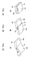
- FIGs. 2A to 2C sequentially show an operation process of the handheld electronic device in FIG. 1 .
- FIGs. 3A to 3C are side views of the handheld electronic device corresponding to the operation process in FIGs. 2A to 2C .
- FIGs. 4A to 4C show a cross-sectional structure of the handheld electronic device corresponding to the operation process in FIGs. 2A to 2C .
- FIG. 1 is an exploded view of a handheld electronic device according to an embodiment of the application.
- a handheld electronic device 100 includes a first body 110, a second body 120, and a rising mechanism 130.
- the first body 110 and the second body 120 are, for example, upper and lower bodies of a slide phone.
- the second body 120 is stacked under the first body 110, and a side of the second body 120 facing the first body 110 has a depression 122.
- the rising mechanism 130 is connected between the first body 110 and the second body 120.
- the rising mechanism 130 includes a rising module 136, a first plate 132, and a second plate 134.
- the second plate 134 is fixed on the first body 110, and the first plate 132 is fixed on the rising module 136.
- the second plate 134 is connected between the first body 110 and the first plate 132, and the first plate 132 is slidably coupled to the second plate 134, such that the first body 110 is capable of sliding relative to the second body 120.
- the rising module 136 of this embodiment is, for example, a four bar linkage, and includes first links 136a and second links 136b.
- the first links 136a and the second links 136b are respectively pivoted between the first plate 132 and the second body 120, in which the second links 136b are connected to an end 132a of the first plate 132, and the first links 136a are connected to the other end of the first plate 132. Moreover, the first links 136a and the second links 136b have different lengths, such that when pivotally rotating relative to the second body 120, the first links 136a and the second links 136b drive the first plate 132 to obliquely enter the depression 122 of the second body 120.
- the rising module 136 of this embodiment may be replaced by other mechanisms, so as to raise the second body 120.
- the rising module 136 may be replaced by a torsion hinge, so as to raise the second body 120.
- the rising mechanism 130 further includes an elastic member 140 connected between the second body 120 and the first links 136a.
- the elastic member 140 includes a torsion spring, for providing a force required to enable the first links 136a to pivotally rotate relative to the second body 120.
- Another elastic member (not shown), for example, a wind spring, a coil spring, or other elastic members capable of generating a semi-auto sliding effect, may be disposed between the second plate 134 and the first plate 132, so as to provide a restoring force and a driving force required when the first body 110 and the second body 120 are relatively spread or closed.
- the handheld electronic device 100 has a semi-auto sliding function.
- FIGs. 2A to 2C sequentially show an operation process of the handheld electronic device 100 of the above embodiment
- FIGs. 3A to 3C are side views of the handheld electronic device 100 corresponding to the operation process in FIGs. 2A to 2C
- FIGs. 4A to 4C further show a cross-sectional structure of the handheld electronic device 100 corresponding to the operation process in FIGs. 2A to 2C , in which the first body 110 is omitted.
- FIGs. 2A to 2C show a process that the first body 110 and the second body 120 of the handheld electronic device 100 change from a state of being stacked over each other to a state of being relatively spread.
- the handheld electronic device 100 is in a stacked state, that is, the first body 110 and the second body 120 are stacked over each other, and the first plate 132, the first links 136a, and the second links 136b are located on initial positions.
- the first body 110 is still located on the second body 120, such that a moment applied by the elastic member 140 to the first links 136a does not function.
- the first body 110 and the first plate 132 are entirely spread to reach the positions shown in FIGs. 2B , 3B , and 4B , an end 112 of the first body 110 slides to a position above the depression 122, and the moment applied by the elastic member 140 to the first links 136a functions to drive the first links 136a to pivotally rotate relative to the second body 120 in a direction R1.
- the electric member 140 is not disposed in this embodiment, the same effect may be achieved through a downward force of pushing the first body 110 by the user.
- the first plate 132 together with the end 112 of the first body 110 obliquely enters the depression 122 of the second body 120 and is located in the depression 122.
- the first body 110 and the second body 120 maintain an angle ⁇ . In this manner, when operating the handheld electronic device 100, the user may hold the second body 120 and view a display interface on the first body 110, so that the operation of the user becomes more convenient.
- an upper surface 110a of the first body 110 and an upper surface 120a of the second body 120 form a continuous surface.
- the upper surface 110a of the first body 110 and the upper surface 120a of the second body 120 nearly have no height difference.
- the above design requirement is achieved, so as to enhance the aesthetic feeling of the appearance of the handheld electronic device 100 and the hand feeling of the user during the operation.
- the user when intending to restore the handheld electronic device 100 in the spread state to the stacked state, the user only needs to reverse the process, such that the first body 110 and the second body 120 being relatively spread are restored to the state of being stacked over each other.
- the other end of the first body 110 relative to the end 12 is pressed downward, the first plate 132 and the end 112 of the first body 110 depart from the depression 122 of the second body 120, and the first plate 132, the second plate 134, and the first body 110 are restored to a horizontal state as shown in FIGs. 2B , 3B , and 4B .
- the first body 110 is pushed in a direction opposite to H1, such that the first body 110 and the second plate 134 are enabled to move from the positions shown in FIGs. 2B , 3B , and 4B to the initial positions shown in FIGs. 2A , 3A , and 4A .
- the elastic member between the second plate 134 and the first plate 132 also provides the semi-auto sliding effect. Therefore, after moving relative to the second body 120 for a certain distance, the first body 110 is automatically restored to the state of being stacked over the second body 120 through the elastic restoring force of the elastic member.
- the first body and the second body form an angle after being relatively spread through the rising mechanism, which makes it easy for the user to hold and view the handheld electronic device, thereby increasing the convenience for the user to operate.
- the upper surface of the first body and the upper surface of the second body form a continuous bending surface, so as to simplify the appearance of the handheld electronic device.
Landscapes
- Engineering & Computer Science (AREA)
- Physics & Mathematics (AREA)
- Theoretical Computer Science (AREA)
- Signal Processing (AREA)
- Mathematical Physics (AREA)
- Computer Hardware Design (AREA)
- Human Computer Interaction (AREA)
- General Engineering & Computer Science (AREA)
- General Physics & Mathematics (AREA)
- Telephone Set Structure (AREA)
- Casings For Electric Apparatus (AREA)
Abstract


Description
- The application generally relates to a handheld electronic device and a rising mechanism, in particular, to a handheld electronic device in which two bodies are spread to form an angle, and a rising mechanism capable of enabling two bodies to spread and form an angle.
- Recently, with the development of information technology, it is getting easier to acquire desired information from electronic devices in daily life. Further, due to progress in the industrial technology, various types of handheld electronic devices are developed towards a trend of light, thin, short, and small products. Having the characteristic and advantage of being portable, the handheld electronic devices are widely accepted and applied in daily life.
- Taking cell phones as an example, in order to conveniently carry the cell phones and satisfy different use preferences and demands, in addition to conventional bar phones, the cell phones also include clamshell phones, twist phones, slide phones, and other common types of phones. For a slide phone, its upper and lower bodies are stacked and capable of sliding relative to each other, so as to achieve different operation modes, for example, an opening mode and a closing mode. The stacking of the upper and lower bodies helps to reduce an entire volume of the slide phone, and the upper and lower bodies may be spread under a specific operation mode.
- Here, taking a double-layer slide phone having a keyboard as an example, the slide phone operates in the following manner. A force is applied to make a display screen slide to a side of the keyboard, and the keyboard is thus exposed to enable a user to input easily. However, in this design, the display screen and the keyboard remain in parallel, such that the user needs to change gestures or move the handheld electronic device at any moment to satisfy the demands of inputting through the keyboard and viewing the screen.
- Accordingly, the application is directed to a handheld electronic device and a rising mechanism applicable to the handheld electronic device, so that after being spread, the handheld electronic device is arranged in a manner that is convenient to be held and viewed by a user through the rising mechanism, thereby increasing the convenience for the user to operation.
- The application provides a handheld electronic device, which includes a first body, a second body, and a rising mechanism. The second body is stacked under the first body. A side of the second body facing the first body has a depression. The rising mechanism is disposed in the depression, and connected between the first body and the second body. The rising mechanism is slidably coupled to the first body, so that when the first body and the second body are relatively spread, the first body slides relative to the rising mechanism. When the first body reaches a predetermined position, an end of the first body enters the depression, the rising mechanism drives the first body to rotate relative to the second body, and an upper surface of the first body and an upper surface of the second body form an angle.
- The application provides a rising mechanism, which is adapted to be connected between a first body and a second body, located in a depression of the second body, and slidably coupled to the first body. When the first body and the second body are relatively spread, the first body slides relative to the rising mechanism. After the first body reaches a predetermined position, an end of the first body enters the depression, the rising mechanism drives the first body to rotate relative to the second body, and an upper surface of the first body and an upper surface of the second body form an angle.
- In view of the above, when using the handheld electronic device of the application, the user applies a force to the first body, such that the second body and the first body are relatively spread. After the first body slides to a predetermined position, the rising mechanism drives the first body to rotate relative to the second body and enter the depression of the second body, such that the second body and the first body form an angle. Thereby, the handheld electronic device is easy to be held and viewed, which increases the convenience for the user to operate.
- In order to make the aforementioned and other features and advantages of the application comprehensible, embodiments accompanied with figures are described in detail below.
- The accompanying drawings are included to provide a further understanding of the application, and are incorporated in and constitute a part of this specification. The drawings illustrate embodiments of the application and, together with the description, serve to explain the principles of the application.
-
FIG. 1 is a schematic exploded view of a handheld electronic device according to an embodiment of the application. -
FIGs. 2A to 2C sequentially show an operation process of the handheld electronic device inFIG. 1 . -
FIGs. 3A to 3C are side views of the handheld electronic device corresponding to the operation process inFIGs. 2A to 2C . -
FIGs. 4A to 4C show a cross-sectional structure of the handheld electronic device corresponding to the operation process inFIGs. 2A to 2C . - Reference will now be made in detail to the present embodiments of the application, examples of which are illustrated in the accompanying drawings. Wherever possible, the same reference numbers are used in the drawings and the description to refer to the same or like parts.
-
FIG. 1 is an exploded view of a handheld electronic device according to an embodiment of the application. Referring toFIG. 1 , a handheldelectronic device 100 includes afirst body 110, asecond body 120, and a risingmechanism 130. Thefirst body 110 and thesecond body 120 are, for example, upper and lower bodies of a slide phone. Thesecond body 120 is stacked under thefirst body 110, and a side of thesecond body 120 facing thefirst body 110 has adepression 122. The risingmechanism 130 is connected between thefirst body 110 and thesecond body 120. - In this embodiment, the rising
mechanism 130 includes a risingmodule 136, afirst plate 132, and asecond plate 134. Thesecond plate 134 is fixed on thefirst body 110, and thefirst plate 132 is fixed on the risingmodule 136. Thesecond plate 134 is connected between thefirst body 110 and thefirst plate 132, and thefirst plate 132 is slidably coupled to thesecond plate 134, such that thefirst body 110 is capable of sliding relative to thesecond body 120. The risingmodule 136 of this embodiment is, for example, a four bar linkage, and includesfirst links 136a andsecond links 136b. Thefirst links 136a and thesecond links 136b are respectively pivoted between thefirst plate 132 and thesecond body 120, in which thesecond links 136b are connected to an end 132a of thefirst plate 132, and thefirst links 136a are connected to the other end of thefirst plate 132. Moreover, thefirst links 136a and thesecond links 136b have different lengths, such that when pivotally rotating relative to thesecond body 120, thefirst links 136a and thesecond links 136b drive thefirst plate 132 to obliquely enter thedepression 122 of thesecond body 120. It should be noted that the risingmodule 136 of this embodiment may be replaced by other mechanisms, so as to raise thesecond body 120. For example, the risingmodule 136 may be replaced by a torsion hinge, so as to raise thesecond body 120. - In addition, the rising
mechanism 130 further includes anelastic member 140 connected between thesecond body 120 and thefirst links 136a. Theelastic member 140 includes a torsion spring, for providing a force required to enable thefirst links 136a to pivotally rotate relative to thesecond body 120. Another elastic member (not shown), for example, a wind spring, a coil spring, or other elastic members capable of generating a semi-auto sliding effect, may be disposed between thesecond plate 134 and thefirst plate 132, so as to provide a restoring force and a driving force required when thefirst body 110 and thesecond body 120 are relatively spread or closed. In other words, the handheldelectronic device 100 has a semi-auto sliding function. -
FIGs. 2A to 2C sequentially show an operation process of the handheldelectronic device 100 of the above embodiment, andFIGs. 3A to 3C are side views of the handheldelectronic device 100 corresponding to the operation process inFIGs. 2A to 2C . Moreover, in order to clearly describe the operation of the risingmechanism 130 of the handheldelectronic device 100,FIGs. 4A to 4C further show a cross-sectional structure of the handheldelectronic device 100 corresponding to the operation process inFIGs. 2A to 2C , in which thefirst body 110 is omitted. -
FIGs. 2A to 2C show a process that thefirst body 110 and thesecond body 120 of the handheldelectronic device 100 change from a state of being stacked over each other to a state of being relatively spread. Firstly, referring toFIGs. 2A ,3A , and4A , the handheldelectronic device 100 is in a stacked state, that is, thefirst body 110 and thesecond body 120 are stacked over each other, and thefirst plate 132, thefirst links 136a, and thesecond links 136b are located on initial positions. Here, thefirst body 110 is still located on thesecond body 120, such that a moment applied by theelastic member 140 to thefirst links 136a does not function. - Next, referring to
FIGs. 2B ,3B , and4B , when a user applies a force in a force application direction H1 to push thefirst body 110 forward for a certain distance, thesecond plate 134 moves relative to thefirst plate 132. After thesecond plate 134 reaches a predetermined position, the elastic member between thesecond plate 134 and thefirst plate 132 releases an originally stored elastic potential energy, so as to drive thesecond plate 134 together with thefirst body 110 located on thesecond plate 134 to move relative to thesecond body 120 and thefirst plate 132, thereby achieving the semi-auto sliding effect. - Afterward, referring to
FIGs. 2C ,3C , and4C , thefirst body 110 and thefirst plate 132 are entirely spread to reach the positions shown inFIGs. 2B ,3B , and4B , anend 112 of thefirst body 110 slides to a position above thedepression 122, and the moment applied by theelastic member 140 to thefirst links 136a functions to drive thefirst links 136a to pivotally rotate relative to thesecond body 120 in a direction R1. However, even if theelectric member 140 is not disposed in this embodiment, the same effect may be achieved through a downward force of pushing thefirst body 110 by the user. - In this embodiment, as the
second links 136b and thefirst links 136a have different lengths, under the driving force of thefirst links 136a and the actuation of thesecond links 136b, thefirst plate 132 together with theend 112 of thefirst body 110 obliquely enters thedepression 122 of thesecond body 120 and is located in thedepression 122. In other words, thefirst body 110 and thesecond body 120 maintain an angle θ. In this manner, when operating the handheldelectronic device 100, the user may hold thesecond body 120 and view a display interface on thefirst body 110, so that the operation of the user becomes more convenient. - In addition, in this embodiment, an
upper surface 110a of thefirst body 110 and anupper surface 120a of thesecond body 120 form a continuous surface. In other words, theupper surface 110a of thefirst body 110 and theupper surface 120a of thesecond body 120 nearly have no height difference. Particularly, by adjusting a depth of thedepression 122 of thesecond body 120, the lengths and moving paths of thefirst links 136a and thesecond links 136b, a thickness of thefirst body 110, and other design parameters, the above design requirement is achieved, so as to enhance the aesthetic feeling of the appearance of the handheldelectronic device 100 and the hand feeling of the user during the operation. - In another aspect, when intending to restore the handheld
electronic device 100 in the spread state to the stacked state, the user only needs to reverse the process, such that thefirst body 110 and thesecond body 120 being relatively spread are restored to the state of being stacked over each other. Briefly, under the state as shown inFIGs. 2C ,3C , and4C , the other end of thefirst body 110 relative to the end 12 is pressed downward, thefirst plate 132 and theend 112 of thefirst body 110 depart from thedepression 122 of thesecond body 120, and thefirst plate 132, thesecond plate 134, and thefirst body 110 are restored to a horizontal state as shown inFIGs. 2B ,3B , and4B . Next, thefirst body 110 is pushed in a direction opposite to H1, such that thefirst body 110 and thesecond plate 134 are enabled to move from the positions shown inFIGs. 2B ,3B , and4B to the initial positions shown inFIGs. 2A ,3A , and4A . During the process that thefirst body 110 and thesecond plate 134 are enabled to move from the positions shown inFIGs. 2B ,3B , and4B to the initial positions shown inFIGs. 2A ,3A , and4A , the elastic member between thesecond plate 134 and thefirst plate 132 also provides the semi-auto sliding effect. Therefore, after moving relative to thesecond body 120 for a certain distance, thefirst body 110 is automatically restored to the state of being stacked over thesecond body 120 through the elastic restoring force of the elastic member. - To sum up, in the handheld electronic device according to the present application, the first body and the second body form an angle after being relatively spread through the rising mechanism, which makes it easy for the user to hold and view the handheld electronic device, thereby increasing the convenience for the user to operate. In addition, according to the present application, after the handheld electronic device is spread, the upper surface of the first body and the upper surface of the second body form a continuous bending surface, so as to simplify the appearance of the handheld electronic device.
- It will be apparent to those skilled in the art that various modifications and variations can be made to the structure of the present application without departing from the scope or spirit of the application. In view of the foregoing, it is intended that the present application cover modifications and variations of this application provided they fall within the scope of the following claims and their equivalents.
Claims (8)
- A handheld electronic device, comprising:a first body;a second body, stacked under the first body, wherein a side of the second body facing the first body comprises a depression; anda rising mechanism, connected between the first body and the second body, and slidably coupled to the first body, wherein when the first body and the second body are relatively spread, the first body slides relative to the rising mechanism, and when the first body reaches a predetermined position, an end of the first body enters the depression, the rising mechanism drives the first body to rotate relative to the second body, and an upper surface of the first body and an upper surface of the second body form an angle.
- The handheld electronic device according to claim 1, wherein after the first body enters the depression, the upper surface of the first body and the upper surface of the second body form a continuous surface.
- The handheld electronic device according to claim 1, wherein the rising mechanism comprises a rising module, a first plate, and a second plate, the second plate is fixed on the first body, the first plate is fixed on the rising module, and the first plate is slidably coupled to the second plate.
- The handheld electronic device according to claim 3, wherein the rising module comprises a plurality of links, and two ends of each link are respectively pivoted to the second body and the first plate.
- The handheld electronic device according to claim 4, wherein the links are configured as a four bar linkage.
- The handheld electronic device according to claim 4, wherein the rising mechanism further comprises an elastic member, connected between the second body and the links.
- The handheld electronic device according to claim 6, wherein the elastic member comprises a torsion spring.
- The handheld electronic device according to claim 3, wherein the rising module comprises a torsion hinge.
Applications Claiming Priority (1)
| Application Number | Priority Date | Filing Date | Title |
|---|---|---|---|
| TW098126812A TWI365036B (en) | 2009-08-10 | 2009-08-10 | Handheld electronic device and rising mechanism |
Publications (2)
| Publication Number | Publication Date |
|---|---|
| EP2285074A1 true EP2285074A1 (en) | 2011-02-16 |
| EP2285074B1 EP2285074B1 (en) | 2012-02-01 |
Family
ID=41566167
Family Applications (1)
| Application Number | Title | Priority Date | Filing Date |
|---|---|---|---|
| EP09015258A Active EP2285074B1 (en) | 2009-08-10 | 2009-12-09 | Handheld electronic device and rising mechanism |
Country Status (5)
| Country | Link |
|---|---|
| US (1) | US8183459B2 (en) |
| EP (1) | EP2285074B1 (en) |
| JP (1) | JP3162363U (en) |
| AT (1) | ATE544287T1 (en) |
| TW (1) | TWI365036B (en) |
Families Citing this family (7)
| Publication number | Priority date | Publication date | Assignee | Title |
|---|---|---|---|---|
| TWM398741U (en) * | 2010-07-28 | 2011-02-21 | Hon Hai Prec Ind Co Ltd | Slidable electronic device |
| US8787016B2 (en) | 2011-07-06 | 2014-07-22 | Apple Inc. | Flexible display devices |
| JP5910409B2 (en) * | 2012-08-10 | 2016-04-27 | 富士通株式会社 | Information device and information device link mechanism |
| KR102370015B1 (en) * | 2014-11-25 | 2022-03-07 | 삼성디스플레이 주식회사 | Display apparatus |
| US11086355B2 (en) * | 2016-10-31 | 2021-08-10 | Lenovo (Singapore) Pte. Ltd. | Electronic device with collapsing interface components |
| KR102908060B1 (en) * | 2020-04-08 | 2026-01-06 | 엘지전자 주식회사 | Air Cleaner |
| CN222924783U (en) * | 2024-05-27 | 2025-05-30 | 杭州安费诺飞凤通信部品有限公司 | Buckle type auxiliary support hinge |
Citations (4)
| Publication number | Priority date | Publication date | Assignee | Title |
|---|---|---|---|---|
| JP2004235687A (en) * | 2003-01-28 | 2004-08-19 | Sanyo Electric Co Ltd | Portable radio terminal |
| US20050044665A1 (en) * | 2003-08-18 | 2005-03-03 | Ryuta Kuramochi | Slide hinge for small-sized information terminal |
| WO2006106374A1 (en) | 2005-04-06 | 2006-10-12 | Nokia Corporation | Extensible mobile electronic device |
| US20070243896A1 (en) | 2006-04-17 | 2007-10-18 | Esa-Sakari Maatta | Dual lever slide mechanism for extendible device housings |
Family Cites Families (6)
| Publication number | Priority date | Publication date | Assignee | Title |
|---|---|---|---|---|
| US7688970B2 (en) * | 2004-09-17 | 2010-03-30 | Motorola, Inc. | Interconnect assembly for a clam style portable communication device |
| TWI260193B (en) * | 2005-04-15 | 2006-08-11 | Benq Corp | Mobile device |
| US8073506B2 (en) * | 2007-07-06 | 2011-12-06 | Panasonic Corporation | Mobile terminal |
| US8099134B2 (en) * | 2008-12-19 | 2012-01-17 | Verizon Patent And Licensing Inc. | Visual manipulation of audio |
| CN101901884A (en) * | 2009-06-01 | 2010-12-01 | 深圳富泰宏精密工业有限公司 | Battery clamping mechanism and portable electronic device applying same |
| US8095191B2 (en) * | 2009-07-06 | 2012-01-10 | Motorola Mobility, Inc. | Detection and function of seven self-supported orientations in a portable device |
-
2009
- 2009-08-10 TW TW098126812A patent/TWI365036B/en active
- 2009-12-09 EP EP09015258A patent/EP2285074B1/en active Active
- 2009-12-09 AT AT09015258T patent/ATE544287T1/en active
- 2009-12-10 US US12/635,663 patent/US8183459B2/en active Active
-
2010
- 2010-03-11 JP JP2010001564U patent/JP3162363U/en not_active Expired - Lifetime
Patent Citations (4)
| Publication number | Priority date | Publication date | Assignee | Title |
|---|---|---|---|---|
| JP2004235687A (en) * | 2003-01-28 | 2004-08-19 | Sanyo Electric Co Ltd | Portable radio terminal |
| US20050044665A1 (en) * | 2003-08-18 | 2005-03-03 | Ryuta Kuramochi | Slide hinge for small-sized information terminal |
| WO2006106374A1 (en) | 2005-04-06 | 2006-10-12 | Nokia Corporation | Extensible mobile electronic device |
| US20070243896A1 (en) | 2006-04-17 | 2007-10-18 | Esa-Sakari Maatta | Dual lever slide mechanism for extendible device housings |
Also Published As
| Publication number | Publication date |
|---|---|
| JP3162363U (en) | 2010-09-02 |
| US20110030988A1 (en) | 2011-02-10 |
| US8183459B2 (en) | 2012-05-22 |
| EP2285074B1 (en) | 2012-02-01 |
| TWI365036B (en) | 2012-05-21 |
| TW201106846A (en) | 2011-02-16 |
| ATE544287T1 (en) | 2012-02-15 |
Similar Documents
| Publication | Publication Date | Title |
|---|---|---|
| US8199475B2 (en) | Electronic device | |
| US8183459B2 (en) | Handheld electronic device and rising mechanism | |
| JP5085725B2 (en) | Openable small electronic equipment | |
| US8140135B2 (en) | Handheld electronic device | |
| US7583496B2 (en) | Portable electronic device | |
| CN102082845B (en) | Electronic device | |
| EP2034700A1 (en) | Sliding-type mobile communication terminal | |
| KR100662869B1 (en) | terminal | |
| EP2197182A1 (en) | Handheld electronic device and operating method thereof | |
| EP2475152B1 (en) | Slidable handheld electronic device | |
| US7747298B2 (en) | Sliding device for portable terminal | |
| US8422215B2 (en) | Handheld electronic device | |
| US8724316B2 (en) | Handheld electronic device | |
| CN101997936B (en) | Handheld Electronic Devices and Lifting Mechanisms | |
| CN101753642B (en) | Sliding cover type handheld mobile device with large sliding stroke | |
| EP2299664B1 (en) | Electronic device | |
| CN201204772Y (en) | Sliding closure mechanism with semi-automatic opening and closing function | |
| KR20110078094A (en) | Sliding Handheld Terminal | |
| CN102340951B (en) | handheld electronic device | |
| KR200382516Y1 (en) | Sliding type opening and closing mechanism of cellular phone | |
| KR100692715B1 (en) | Slide module and slide type mobile communication terminal having the same | |
| KR100833167B1 (en) | Mobile communication terminal | |
| TW201129059A (en) | Slidable electronic device | |
| JP2012186671A (en) | Terminal device | |
| KR20130079720A (en) | Slide apparatus and the electronic equipment having it |
Legal Events
| Date | Code | Title | Description |
|---|---|---|---|
| PUAI | Public reference made under article 153(3) epc to a published international application that has entered the european phase |
Free format text: ORIGINAL CODE: 0009012 |
|
| 17P | Request for examination filed |
Effective date: 20091209 |
|
| AK | Designated contracting states |
Kind code of ref document: A1 Designated state(s): AT BE BG CH CY CZ DE DK EE ES FI FR GB GR HR HU IE IS IT LI LT LU LV MC MK MT NL NO PL PT RO SE SI SK SM TR |
|
| AX | Request for extension of the european patent |
Extension state: AL BA RS |
|
| RIC1 | Information provided on ipc code assigned before grant |
Ipc: H04M 1/02 20060101AFI20110217BHEP Ipc: G06F 1/16 20060101ALI20110217BHEP |
|
| GRAP | Despatch of communication of intention to grant a patent |
Free format text: ORIGINAL CODE: EPIDOSNIGR1 |
|
| GRAS | Grant fee paid |
Free format text: ORIGINAL CODE: EPIDOSNIGR3 |
|
| RAP1 | Party data changed (applicant data changed or rights of an application transferred) |
Owner name: HTC CORPORATION |
|
| GRAA | (expected) grant |
Free format text: ORIGINAL CODE: 0009210 |
|
| AK | Designated contracting states |
Kind code of ref document: B1 Designated state(s): AT BE BG CH CY CZ DE DK EE ES FI FR GB GR HR HU IE IS IT LI LT LU LV MC MK MT NL NO PL PT RO SE SI SK SM TR |
|
| REG | Reference to a national code |
Ref country code: GB Ref legal event code: FG4D |
|
| REG | Reference to a national code |
Ref country code: AT Ref legal event code: REF Ref document number: 544287 Country of ref document: AT Kind code of ref document: T Effective date: 20120215 Ref country code: CH Ref legal event code: EP |
|
| REG | Reference to a national code |
Ref country code: NL Ref legal event code: T3 |
|
| REG | Reference to a national code |
Ref country code: DE Ref legal event code: R096 Ref document number: 602009004977 Country of ref document: DE Effective date: 20120329 |
|
| LTIE | Lt: invalidation of european patent or patent extension |
Effective date: 20120201 |
|
| PG25 | Lapsed in a contracting state [announced via postgrant information from national office to epo] |
Ref country code: NO Free format text: LAPSE BECAUSE OF FAILURE TO SUBMIT A TRANSLATION OF THE DESCRIPTION OR TO PAY THE FEE WITHIN THE PRESCRIBED TIME-LIMIT Effective date: 20120501 Ref country code: IS Free format text: LAPSE BECAUSE OF FAILURE TO SUBMIT A TRANSLATION OF THE DESCRIPTION OR TO PAY THE FEE WITHIN THE PRESCRIBED TIME-LIMIT Effective date: 20120601 Ref country code: LT Free format text: LAPSE BECAUSE OF FAILURE TO SUBMIT A TRANSLATION OF THE DESCRIPTION OR TO PAY THE FEE WITHIN THE PRESCRIBED TIME-LIMIT Effective date: 20120201 Ref country code: HR Free format text: LAPSE BECAUSE OF FAILURE TO SUBMIT A TRANSLATION OF THE DESCRIPTION OR TO PAY THE FEE WITHIN THE PRESCRIBED TIME-LIMIT Effective date: 20120201 |
|
| PG25 | Lapsed in a contracting state [announced via postgrant information from national office to epo] |
Ref country code: LV Free format text: LAPSE BECAUSE OF FAILURE TO SUBMIT A TRANSLATION OF THE DESCRIPTION OR TO PAY THE FEE WITHIN THE PRESCRIBED TIME-LIMIT Effective date: 20120201 Ref country code: GR Free format text: LAPSE BECAUSE OF FAILURE TO SUBMIT A TRANSLATION OF THE DESCRIPTION OR TO PAY THE FEE WITHIN THE PRESCRIBED TIME-LIMIT Effective date: 20120502 Ref country code: PT Free format text: LAPSE BECAUSE OF FAILURE TO SUBMIT A TRANSLATION OF THE DESCRIPTION OR TO PAY THE FEE WITHIN THE PRESCRIBED TIME-LIMIT Effective date: 20120601 Ref country code: PL Free format text: LAPSE BECAUSE OF FAILURE TO SUBMIT A TRANSLATION OF THE DESCRIPTION OR TO PAY THE FEE WITHIN THE PRESCRIBED TIME-LIMIT Effective date: 20120201 Ref country code: FI Free format text: LAPSE BECAUSE OF FAILURE TO SUBMIT A TRANSLATION OF THE DESCRIPTION OR TO PAY THE FEE WITHIN THE PRESCRIBED TIME-LIMIT Effective date: 20120201 Ref country code: BE Free format text: LAPSE BECAUSE OF FAILURE TO SUBMIT A TRANSLATION OF THE DESCRIPTION OR TO PAY THE FEE WITHIN THE PRESCRIBED TIME-LIMIT Effective date: 20120201 |
|
| REG | Reference to a national code |
Ref country code: AT Ref legal event code: MK05 Ref document number: 544287 Country of ref document: AT Kind code of ref document: T Effective date: 20120201 |
|
| PG25 | Lapsed in a contracting state [announced via postgrant information from national office to epo] |
Ref country code: CY Free format text: LAPSE BECAUSE OF FAILURE TO SUBMIT A TRANSLATION OF THE DESCRIPTION OR TO PAY THE FEE WITHIN THE PRESCRIBED TIME-LIMIT Effective date: 20120201 |
|
| PG25 | Lapsed in a contracting state [announced via postgrant information from national office to epo] |
Ref country code: SE Free format text: LAPSE BECAUSE OF FAILURE TO SUBMIT A TRANSLATION OF THE DESCRIPTION OR TO PAY THE FEE WITHIN THE PRESCRIBED TIME-LIMIT Effective date: 20120201 Ref country code: DK Free format text: LAPSE BECAUSE OF FAILURE TO SUBMIT A TRANSLATION OF THE DESCRIPTION OR TO PAY THE FEE WITHIN THE PRESCRIBED TIME-LIMIT Effective date: 20120201 Ref country code: CZ Free format text: LAPSE BECAUSE OF FAILURE TO SUBMIT A TRANSLATION OF THE DESCRIPTION OR TO PAY THE FEE WITHIN THE PRESCRIBED TIME-LIMIT Effective date: 20120201 Ref country code: EE Free format text: LAPSE BECAUSE OF FAILURE TO SUBMIT A TRANSLATION OF THE DESCRIPTION OR TO PAY THE FEE WITHIN THE PRESCRIBED TIME-LIMIT Effective date: 20120201 Ref country code: SI Free format text: LAPSE BECAUSE OF FAILURE TO SUBMIT A TRANSLATION OF THE DESCRIPTION OR TO PAY THE FEE WITHIN THE PRESCRIBED TIME-LIMIT Effective date: 20120201 Ref country code: RO Free format text: LAPSE BECAUSE OF FAILURE TO SUBMIT A TRANSLATION OF THE DESCRIPTION OR TO PAY THE FEE WITHIN THE PRESCRIBED TIME-LIMIT Effective date: 20120201 |
|
| PG25 | Lapsed in a contracting state [announced via postgrant information from national office to epo] |
Ref country code: IT Free format text: LAPSE BECAUSE OF FAILURE TO SUBMIT A TRANSLATION OF THE DESCRIPTION OR TO PAY THE FEE WITHIN THE PRESCRIBED TIME-LIMIT Effective date: 20120201 Ref country code: SK Free format text: LAPSE BECAUSE OF FAILURE TO SUBMIT A TRANSLATION OF THE DESCRIPTION OR TO PAY THE FEE WITHIN THE PRESCRIBED TIME-LIMIT Effective date: 20120201 |
|
| PLBE | No opposition filed within time limit |
Free format text: ORIGINAL CODE: 0009261 |
|
| STAA | Information on the status of an ep patent application or granted ep patent |
Free format text: STATUS: NO OPPOSITION FILED WITHIN TIME LIMIT |
|
| 26N | No opposition filed |
Effective date: 20121105 |
|
| PG25 | Lapsed in a contracting state [announced via postgrant information from national office to epo] |
Ref country code: AT Free format text: LAPSE BECAUSE OF FAILURE TO SUBMIT A TRANSLATION OF THE DESCRIPTION OR TO PAY THE FEE WITHIN THE PRESCRIBED TIME-LIMIT Effective date: 20120201 |
|
| REG | Reference to a national code |
Ref country code: DE Ref legal event code: R097 Ref document number: 602009004977 Country of ref document: DE Effective date: 20121105 |
|
| PG25 | Lapsed in a contracting state [announced via postgrant information from national office to epo] |
Ref country code: ES Free format text: LAPSE BECAUSE OF FAILURE TO SUBMIT A TRANSLATION OF THE DESCRIPTION OR TO PAY THE FEE WITHIN THE PRESCRIBED TIME-LIMIT Effective date: 20120512 |
|
| PG25 | Lapsed in a contracting state [announced via postgrant information from national office to epo] |
Ref country code: MC Free format text: LAPSE BECAUSE OF NON-PAYMENT OF DUE FEES Effective date: 20121231 Ref country code: BG Free format text: LAPSE BECAUSE OF FAILURE TO SUBMIT A TRANSLATION OF THE DESCRIPTION OR TO PAY THE FEE WITHIN THE PRESCRIBED TIME-LIMIT Effective date: 20120501 |
|
| REG | Reference to a national code |
Ref country code: IE Ref legal event code: MM4A |
|
| PG25 | Lapsed in a contracting state [announced via postgrant information from national office to epo] |
Ref country code: IE Free format text: LAPSE BECAUSE OF NON-PAYMENT OF DUE FEES Effective date: 20121209 |
|
| PG25 | Lapsed in a contracting state [announced via postgrant information from national office to epo] |
Ref country code: MT Free format text: LAPSE BECAUSE OF FAILURE TO SUBMIT A TRANSLATION OF THE DESCRIPTION OR TO PAY THE FEE WITHIN THE PRESCRIBED TIME-LIMIT Effective date: 20120201 |
|
| PG25 | Lapsed in a contracting state [announced via postgrant information from national office to epo] |
Ref country code: TR Free format text: LAPSE BECAUSE OF FAILURE TO SUBMIT A TRANSLATION OF THE DESCRIPTION OR TO PAY THE FEE WITHIN THE PRESCRIBED TIME-LIMIT Effective date: 20120201 |
|
| PG25 | Lapsed in a contracting state [announced via postgrant information from national office to epo] |
Ref country code: SM Free format text: LAPSE BECAUSE OF FAILURE TO SUBMIT A TRANSLATION OF THE DESCRIPTION OR TO PAY THE FEE WITHIN THE PRESCRIBED TIME-LIMIT Effective date: 20120201 Ref country code: LU Free format text: LAPSE BECAUSE OF NON-PAYMENT OF DUE FEES Effective date: 20121209 |
|
| PG25 | Lapsed in a contracting state [announced via postgrant information from national office to epo] |
Ref country code: HU Free format text: LAPSE BECAUSE OF FAILURE TO SUBMIT A TRANSLATION OF THE DESCRIPTION OR TO PAY THE FEE WITHIN THE PRESCRIBED TIME-LIMIT Effective date: 20091209 |
|
| REG | Reference to a national code |
Ref country code: CH Ref legal event code: PL |
|
| PG25 | Lapsed in a contracting state [announced via postgrant information from national office to epo] |
Ref country code: LI Free format text: LAPSE BECAUSE OF NON-PAYMENT OF DUE FEES Effective date: 20131231 Ref country code: CH Free format text: LAPSE BECAUSE OF NON-PAYMENT OF DUE FEES Effective date: 20131231 |
|
| PG25 | Lapsed in a contracting state [announced via postgrant information from national office to epo] |
Ref country code: MK Free format text: LAPSE BECAUSE OF FAILURE TO SUBMIT A TRANSLATION OF THE DESCRIPTION OR TO PAY THE FEE WITHIN THE PRESCRIBED TIME-LIMIT Effective date: 20120201 |
|
| REG | Reference to a national code |
Ref country code: FR Ref legal event code: PLFP Year of fee payment: 7 |
|
| REG | Reference to a national code |
Ref country code: FR Ref legal event code: PLFP Year of fee payment: 8 |
|
| REG | Reference to a national code |
Ref country code: FR Ref legal event code: PLFP Year of fee payment: 9 |
|
| P01 | Opt-out of the competence of the unified patent court (upc) registered |
Effective date: 20230602 |
|
| PGFP | Annual fee paid to national office [announced via postgrant information from national office to epo] |
Ref country code: NL Payment date: 20241004 Year of fee payment: 16 |
|
| PGFP | Annual fee paid to national office [announced via postgrant information from national office to epo] |
Ref country code: DE Payment date: 20241001 Year of fee payment: 16 |
|
| PGFP | Annual fee paid to national office [announced via postgrant information from national office to epo] |
Ref country code: GB Payment date: 20241001 Year of fee payment: 16 |
|
| PGFP | Annual fee paid to national office [announced via postgrant information from national office to epo] |
Ref country code: FR Payment date: 20241001 Year of fee payment: 16 |