EP2285033A1 - Modification of data transmission regime - Google Patents
Modification of data transmission regime Download PDFInfo
- Publication number
- EP2285033A1 EP2285033A1 EP09360040A EP09360040A EP2285033A1 EP 2285033 A1 EP2285033 A1 EP 2285033A1 EP 09360040 A EP09360040 A EP 09360040A EP 09360040 A EP09360040 A EP 09360040A EP 2285033 A1 EP2285033 A1 EP 2285033A1
- Authority
- EP
- European Patent Office
- Prior art keywords
- data packet
- regime
- transmission
- data
- modification
- Prior art date
- Legal status (The legal status is an assumption and is not a legal conclusion. Google has not performed a legal analysis and makes no representation as to the accuracy of the status listed.)
- Granted
Links
Images




Classifications
-
- H—ELECTRICITY
- H04—ELECTRIC COMMUNICATION TECHNIQUE
- H04L—TRANSMISSION OF DIGITAL INFORMATION, e.g. TELEGRAPHIC COMMUNICATION
- H04L1/00—Arrangements for detecting or preventing errors in the information received
- H04L1/12—Arrangements for detecting or preventing errors in the information received by using return channel
- H04L1/16—Arrangements for detecting or preventing errors in the information received by using return channel in which the return channel carries supervisory signals, e.g. repetition request signals
- H04L1/18—Automatic repetition systems, e.g. Van Duuren systems
- H04L1/1867—Arrangements specially adapted for the transmitter end
- H04L1/188—Time-out mechanisms
-
- H—ELECTRICITY
- H04—ELECTRIC COMMUNICATION TECHNIQUE
- H04L—TRANSMISSION OF DIGITAL INFORMATION, e.g. TELEGRAPHIC COMMUNICATION
- H04L1/00—Arrangements for detecting or preventing errors in the information received
- H04L1/0001—Systems modifying transmission characteristics according to link quality, e.g. power backoff
- H04L1/0023—Systems modifying transmission characteristics according to link quality, e.g. power backoff characterised by the signalling
- H04L1/0025—Transmission of mode-switching indication
-
- H—ELECTRICITY
- H04—ELECTRIC COMMUNICATION TECHNIQUE
- H04L—TRANSMISSION OF DIGITAL INFORMATION, e.g. TELEGRAPHIC COMMUNICATION
- H04L1/00—Arrangements for detecting or preventing errors in the information received
- H04L1/12—Arrangements for detecting or preventing errors in the information received by using return channel
- H04L1/16—Arrangements for detecting or preventing errors in the information received by using return channel in which the return channel carries supervisory signals, e.g. repetition request signals
- H04L1/18—Automatic repetition systems, e.g. Van Duuren systems
- H04L1/1825—Adaptation of specific ARQ protocol parameters according to transmission conditions
-
- H—ELECTRICITY
- H04—ELECTRIC COMMUNICATION TECHNIQUE
- H04W—WIRELESS COMMUNICATION NETWORKS
- H04W52/00—Power management, e.g. Transmission Power Control [TPC] or power classes
- H04W52/04—Transmission power control [TPC]
- H04W52/30—Transmission power control [TPC] using constraints in the total amount of available transmission power
- H04W52/36—Transmission power control [TPC] using constraints in the total amount of available transmission power with a discrete range or set of values, e.g. step size, ramping or offsets
-
- H—ELECTRICITY
- H04—ELECTRIC COMMUNICATION TECHNIQUE
- H04W—WIRELESS COMMUNICATION NETWORKS
- H04W52/00—Power management, e.g. Transmission Power Control [TPC] or power classes
- H04W52/04—Transmission power control [TPC]
- H04W52/38—TPC being performed in particular situations
- H04W52/48—TPC being performed in particular situations during retransmission after error or non-acknowledgment
-
- H—ELECTRICITY
- H04—ELECTRIC COMMUNICATION TECHNIQUE
- H04L—TRANSMISSION OF DIGITAL INFORMATION, e.g. TELEGRAPHIC COMMUNICATION
- H04L1/00—Arrangements for detecting or preventing errors in the information received
- H04L1/12—Arrangements for detecting or preventing errors in the information received by using return channel
- H04L1/16—Arrangements for detecting or preventing errors in the information received by using return channel in which the return channel carries supervisory signals, e.g. repetition request signals
- H04L1/18—Automatic repetition systems, e.g. Van Duuren systems
- H04L1/1822—Automatic repetition systems, e.g. Van Duuren systems involving configuration of automatic repeat request [ARQ] with parallel processes
-
- H—ELECTRICITY
- H04—ELECTRIC COMMUNICATION TECHNIQUE
- H04W—WIRELESS COMMUNICATION NETWORKS
- H04W52/00—Power management, e.g. Transmission Power Control [TPC] or power classes
- H04W52/04—Transmission power control [TPC]
- H04W52/30—Transmission power control [TPC] using constraints in the total amount of available transmission power
- H04W52/36—Transmission power control [TPC] using constraints in the total amount of available transmission power with a discrete range or set of values, e.g. step size, ramping or offsets
- H04W52/362—Aspects of the step size
-
- H—ELECTRICITY
- H04—ELECTRIC COMMUNICATION TECHNIQUE
- H04W—WIRELESS COMMUNICATION NETWORKS
- H04W52/00—Power management, e.g. Transmission Power Control [TPC] or power classes
- H04W52/04—Transmission power control [TPC]
- H04W52/30—Transmission power control [TPC] using constraints in the total amount of available transmission power
- H04W52/36—Transmission power control [TPC] using constraints in the total amount of available transmission power with a discrete range or set of values, e.g. step size, ramping or offsets
- H04W52/367—Power values between minimum and maximum limits, e.g. dynamic range
Definitions
- the present invention relates to a method of modifying a data packet transmission regime in a wireless telecommunications network in response to a triggering event, user equipment, a base station and a computer program product.
- Radio coverage is provided to user equipment, for example, mobile telephones, by regions of geographical area.
- the required radio coverage in each geographical area may be provided by means of a radio coverage network which may comprise one or more base stations.
- User equipment located in a geographical area served by a base station receives information and data from the base station and transmits data and information to the base station.
- HSUPA high speed uplink packet access
- Packets of data are sent in time blocks of predetermined length.
- the available time blocks in a HSUPA network have a length of 10ms or 2ms.
- Those time blocks are known as data block transmit time intervals (TTI).
- Transmission power available to a base station or user equipment may be limited, for example, to ensure signals are sent at a power level deemed safe for operation, or because a limited amount of power is available from a power source.
- Such an arrangement allows a base station to maintain a larger coverage area, but has the potential disadvantage that outside the area in which 2ms transmit time interval data transmission is available, a user will be forced to operate at the lower data throughput rate offered by a 10ms transmit time interval regime.
- a first aspect provides a method of modifying a data packet transmission regime in a wireless telecommunications network in response to a triggering event, the data packet transmission regime comprising:
- the first aspect recognises that utilising a data transmission regime in which an acknowledgement protocol is operating enables transmission of redundant data packets, or transport blocks of data to be minimised. If a data packet is successfully received and an acknowledgement of successful receipt is received, there is no need to re-send that data packet.
- a method in accordance with the first aspect recognises that repeating transmission of a data packet without knowledge of whether is has successfully reached its destination leads to transmission of redundant data packets and does not optimise overall data throughput in a wireless telecommunications network. It will be appreciated that receipt of a negative acknowledgement, i.e. an indication that the data packet was unsuccessfully received is also considered to be no acknowledgement of successful receipt of a data packet.
- the first aspect further recognises that receiving a request to increase the variable transmission power level beyond a predetermined power threshold can act as a reasonable triggering event. If a request for an increase in power is received, the original operating data transmission regime is not adequately meeting wireless telecommunication network operating targets in some way. If no further power is available for transmission, a different method for attempting to meet operating targets is required.
- Modifying the data packet transmission regime by decreasing the predetermined monitoring period effectively increases the number of retransmissions of a particular data packet. Increasing the number of transmissions, and in particular, retransmitting a particular data packet more often over a particular time period, is likely to result in an improvement to the likelihood that the data packet will be successfully received in that particular time period.
- Repeating transmission of a particular data packet over a period of time increases processing gain of the data packet and can thereby increase coverage area offered in a base station - user equipment interaction in such a wireless telecommunications network.
- the method further comprises the step of decreasing the transmission power level of the data transmission regime in accordance with the received modification signal.
- the trigger event indicates that the original data transmission regime was operating near a predetermined power threshold, decreasing the power of transmissions is likely to have the effect of increasing coverage area.
- the modifying step further comprises the steps of:
- a modification signal relating to reduction of power can be expressed as a change in power offset.
- the modification signal may comprise data obtained from a predetermined or pre-mapped look-up table. That table may contain data relating to appropriate reductions in monitoring period and/or power offset values for a data packet of predetermined size.
- the modifying step further comprises the steps of:
- a data transmission regime therefore sets a target successful transmission time for a data packet of specific packet size to ensure a user experiences an acceptable quality of service.
- the target successful transmission time for a specific packet size is also known as Quality of Service (QoS).
- the data transmission regime further comprises the steps of monitoring for acknowledgement of partial receipt of the data packet; and retransmitting a modified version of the data packet in response to the acknowledgement of partial receipt of the data packet.
- the first aspect may utilise various means for obtaining processing gain by retransmitting a data packet more frequently than in an unmodified data transmission regime. It will be understood that any partially successfully received data packets may be subjected to a chase combining method or an incremental redundancy method. As a result it may be possible to achieve completely successful receipt of a data packet in a shorter time period, thus requiring fewer retransmissions of any given data packet.
- the modification signal generated in response to the triggering information comprises an indication of a number of supportable independent consecutive simultaneous acknowledgement processes; and the step of modifying further comprises a step of calculating a modified predetermined monitoring period by multiplying the indication of a number of supportable simultaneous acknowledgement processes by the fixed transmit time interval; and modifying the data packet transmission regime by setting the predetermined monitoring period in accordance with the calculated modified predetermined monitoring period.
- a reduced predetermined monitoring period may be calculated from a signal relating to other characteristic of the data transmission regime, such as am indication of a number of supportable simultaneous acknowledgement processes.
- said fixed transmit time interval is 2ms or 10ms. Accordingly, it will be understood that the first aspect is particularly useful with respect to known used transmit time intervals in wireless telecommunications networks.
- the unmodified predetermined monitoring period is 16ms or 40ms. It will be appreciated that a standard predetermined monitoring period may be employed in the unmodified data transmission regime.
- the data packet transmission regime comprises a regime for transmitting data packets from user equipment to a base station.
- the data packet transmission regime comprises a regime for transmitting data packets from a base station to user equipment.
- the step of transmitting trigger information relating to the triggering event comprises a step of transmitting trigger information to the base station, and wherein the step of receiving a modification signal generated in response to the triggering information comprises a step of receiving the modification signal from the base station.
- a second aspect provides a computer program product, operable when executed on a computer, to perform the method steps of the first aspect.
- a third aspect provides user equipment operable to modify a data packet transmission regime in a wireless telecommunications network in response to a triggering event, said user equipment comprising:
- the method of the first aspect has particular advantages when implemented in user equipment for use in a wireless telecommunications network.
- user equipment operable to perform the method steps of the first aspect may be operable to achieve a greater geographical coverage, whilst maintaining performance and overall data throughput in interactions with a suitable base station.
- the modification logic is further operable to decrease the transmission power level of the data transmission regime in accordance with the received modification signal.
- the modification logic is further operable to:
- the modifying logic is further operable to:
- the monitoring logic is further operable to monitor for acknowledgement of partial receipt of the data packet; and the transmission logic is further operable to retransmit a modified version of the data packet in response to the acknowledgement of partial receipt of the data packet.
- the modification signal generated in response to the triggering information comprises an indication of a number of supportable simultaneous acknowledgement processes; and the modifying step further comprises a step of calculating a modified predetermined monitoring period by multiplying the indication of a number of supportable simultaneous acknowledgement processes by the fixed transmit time interval; and modifying the data packet transmission regime by setting the predetermined monitoring period in accordance with the calculated modified predetermined monitoring period.
- the fixed transmit time interval is 2ms or 10ms.
- the unmodified predetermined monitoring period is 16ms or 40ms.
- the data packet transmission regime comprises a regime for transmitting data packets from the user equipment to a base station.
- the step of transmitting trigger information relating to the triggering event comprises: a step of transmitting trigger information to the base station, and wherein the step of receiving a modification signal generated in response to the triggering information comprises a step of receiving the modification signal from the base station.
- a fourth aspect provides a base station operable to modify a data packet transmission regime in a wireless telecommunications network in response to a triggering event, said base station comprising:
- the method of the first aspect may also be implemented by a base station for use in a wireless telecommunications system.
- a base station may also be power limited and thus may also achieve greater coverage by modifying a data transmission regime having a fixed TTI by employing a modification according to the method of the first aspect.
- the modification logic is further operable to decrease the transmission power level of the data transmission regime in accordance with the received modification signal.
- the modification logic is further operable to:
- the modifying logic is further operable to:
- the monitoring logic is further operable to monitor for acknowledgement of partial receipt of the data packet; and the transmission logic is further operable to retransmit a modified version of the data packet in response to the acknowledgement of partial receipt of the data packet.
- the modification signal generated in response to the triggering information comprises an indication of a number of supportable simultaneous acknowledgement processes; and the modifying step further comprises a step of calculating a modified predetermined monitoring period by multiplying the indication of a number of supportable simultaneous acknowledgement processes by the fixed transmit time interval; and modifying the data packet transmission regime by setting the predetermined monitoring period in accordance with the calculated modified predetermined monitoring period.
- the fixed transmit time interval is 2ms or 10ms.
- the unmodified predetermined monitoring period is 16ms or 40ms.
- FIG. 1 illustrates a wireless telecommunications system 10 according to one embodiment.
- User equipment 50 roam through the wireless telecommunications system.
- Base stations 20 are provided which support areas of radio coverage 30.
- a number of such base stations 20 are provided and are distributed geographically in order to provide a wide area of coverage to user equipment 50.
- communications may be established between the user equipment and the base station over associated radio links.
- Each base station typically supports a number of sectors within the geographical area of service 30.
- each base station 20 has multiple antennas and signals sent through the different antennas are electronically weighted to provide a sectorised approach.
- Figure 1 illustrates a small subset of the total number of user equipment and base stations that may be present in a typical communications system.
- the wireless communications system is managed by a radio network controller (RNC) 40.
- the radio network controller 40 controls operation of the wireless communications system by communicating with a plurality of base stations over a backhaul communications link 60.
- the network controller also communicates with user equipment 50 via each base station and thus effectively manages the entire wireless communications system.
- a radio network controller 60 maintains a neighbour list which includes information about geographical relationships between sectors supported by base stations 20. In addition, the radio network controller 60 maintains location information which provides information on the location of user equipment 50 within the wireless communication system 10.
- the radio network controller is operable to route traffic via circuit switched and packet switched networks.
- a mobile switching centre is provided with which the radio network controller may communicate.
- the mobile switching centre can communicate with a circuit switched network such as a public switched telephone network (PSTN) 70.
- PSTN public switched telephone network
- SGSNs service general package radio service support nodes
- GGSN gateway general packet support node
- the GGSN can communicate with a packet switched core such as for example, the Internet.
- User equipment 50 typically transmits information and data to a base station 20 so that it can be re-routed within a wireless telecommunications network.
- User equipment may, for example, need to transmit data to the base station in order to relay text messages, voice information when a user is using the equipment to make a telephone call, or other data.
- HSUPA high speed uplink packet access
- Packets of data are sent in time blocks of predetermined length.
- the available time blocks have a length of 10ms or 2ms.
- Those time blocks are known as data block transmit time intervals (TTI).
- telecommunications equipment i.e. a base station or an item of user equipment
- telecommunications equipment will typically need to transmit the data packet on a radio carrier at a higher power for a 2ms transmit time interval than for a 10ms transmit time interval.
- Transmission power available to a base station or user equipment may be limited, for example, to ensure signals are sent at a power level deemed safe for operation, or because a limited amount of power is available form a power source.
- Figure 2 illustrates schematically a data transmission acknowledgement protocol used in a data transmission regime of a telecommunications network 10.
- Figure 2 illustrates schematically transmission of a transport block in a data packet from user equipment 50 to a base station 20 in a HSUPA network operating in a 2ms TTI regime and the operation of an acknowledgement protocol known as a Hybrid Automatic Repeat Request (HARQ).
- HARQ enables fast acknowledgement and consequently fast retransmission of a data packet if required.
- a first data packet TB 1 is transmitted from user equipment and successfully received by base station 20.
- the base station in accordance with the HARQ process, sends an acknowledgement of safe receipt (ACK) of TB1 back to user equipment 50.
- ACK safe receipt
- Figure 2 illustrates a "stop and wait" HARQ protocol in which user equipment waits for acknowledgement of safe receipt of a data packet before sending the next. Since a successful receipt is received in respect of TB1, within a pre-programmed monitoring period, user equipment can transmit a second data packet, TB2.
- the monitoring period in the case shown in Figure 2 is 8 transmit time intervals, i.e. 16ms.
- TB2 is not successfully received at base station 20 and thus the base station generates and sends a negative acknowledgement (NACK).
- NACK negative acknowledgement
- user equipment After waiting the pre-programmed monitoring period and having received a NACK, user equipment retransmits TB2, which is then received successfully by the base station.
- Figure 3 illustrates schematically a data transmission regime using the data transmission acknowledgement protocol of Figure 2 .
- a synchronous HARQ protocol is used.
- That pre-programmed monitoring period is the time between commencement of two transmissions of the same packet of data and has been set in accordance with a reasonable estimate of operative HARQ round trip time.
- the estimate of HARQ round trip time for 2ms TTI and predetermined monitoring period for the 2ms TTI regime has been set at 8TTI (16ms).
- user equipment Whilst waiting for an ACK or NACK from a base station in respect of a given data packet, user equipment can transmit further data packets.
- the base station can also monitor for successful receipt or otherwise of those data packets and it will thus be understood that there are, at most, 8 simultaneous HARQ processes occurring at any given time.
- a data transmission regime using a monitoring period of 16ms is shown.
- eight data packets labelled as TB1 to TB8 are consecutively transmitted by user equipment, one in each 2ms TTI.
- Each data packet is subject to a HARQ process, labelled as "HARQ Pro1" to "HARQ Pro8".
- TB1, TB3, TB4, TB5, TB6 and TB8 are not successfully received by the base station 20 and they are retransmitted in the next sequence of 8 transmitted data packets in the TTI's shown.
- user equipment 50 and base station 20 are aware, via a look up table, that successful reception of a transmitted data packet of a particular size within a target elapsed time period after first transmission will result in a good service experience by a user. That target elapsed time period will depend upon the application being offered.
- the target elapsed time period for video or voice for example, will typically be significantly shorter than the target elapsed time for a data packet relating to a SMS message.
- the target elapsed time period for a data packet of a given size for a given size of data packet is referred to as "Quality of Service".
- User equipment 50 and base station 20 may each have a look up table, giving an initial starting set of parameters within which user equipment 50 can operate for transmission of a data packet, or transport block, of given size for a given application. That look up table is known as a HARQ profile.
- the HARQ profile specifies a power offset and a number of maximum transmissions (including a first transmission) for a data packet of given size, for a particular application, requiring a particular Quality of Service.
- Use of the HARQ protocol in combination with a Quality of Service target allows calculation of some indication of whether user equipment and base station are operating to offer an acceptable level of service to an end user.
- each data packet has a target number of retransmissions.
- the maximum number of transmissions includes the first transmission and all subsequent retransmissions of the same data packet. If a data packet transmitted by user equipment is not successfully received by a base station after the maximum number of transmissions has been made, it is deemed to have failed and a higher level retransmission at the Radio Link Control level is performed. RLC retransmission is slow and thus undesirable.
- the base station indicates to user equipment that it needs to increase the power at which it is transmitting those data packets. It will be understood that increasing the power of transmission of a data packet increases the SNIR and thus increases the chances that data packet will be successfully received by a base station within the Quality of Service target time.
- a base station will be able to terminate retransmission of a data packet if the data packet is successfully received by the base station before the maximum number of transmissions set in the HARQ profile is reached. Early termination of that process results in user equipment achieving a higher total data throughput.
- a Retransmission Sequence Number is used to monitor how often a given data packet is transmitted.
- a radio carrier comprises a plurality of channels.
- a channel upon which data packets are sent from user equipment to a base station relating to user equipment applications (for example, voice, video, SMS) are sent is known as an E-DCH Dedicated Physical Data Channel (E-DPDCH).
- a channel upon which control information relating to the user equipment is sent is known as an E-DCH Dedicated Physical Control Channel (E-DPCCH).
- E-DPCCH E-DCH Dedicated Physical Control Channel
- the RSN is sent on the E-DPCCH channel together with the data packet sent on the data channel.
- a known specification for HSUPA networks allows 2 bits for the RSN. However, the maximum number of transmissions is not limited to 4. Nonetheless, this is not a hindrance, since the RSN does not need to increase for transmissions beyond 4. Furthermore, the existing HARQ profile table allows up to 16 transmissions to meet a particular Quality of Service.
- retransmission of a given data packet is expected after a pre-programmed monitoring period.
- That pre-programmed monitoring period is the time between commencement of two transmissions of the same packet of data and has been fixed in accordance with a reasonable estimate of operative HARQ round trip time.
- the estimate of HARQ round trip time for 2ms TTI and predetermined monitoring period for the 2ms TTI regime has been set at a fixed 8TTI (16ms).
- user equipment 20 is transmitting packets of data to a base station 20 in a 2ms TTI data transmission regime.
- User equipment operates as described in relation to Figures 2 and 3 , aiming to meet a known Quality of Service. If user equipment 50 indicates to a base station that it has reached a predetermined power threshold, base station 20 is operable to send a signal (for example via HS-SCCH) to user equipment 50, instructing that user equipment to reduce the number of simultaneous ongoing HARQ processes from the standard 8 in the 2ms TTI regime to a lower number, for example, 6, 5, 4 or 3. As a result, the user equipment can calculate that the monitoring period for acknowledgement of successful receipt of said data packet, and the retransmission wait for a data packet is reduced.
- a signal for example via HS-SCCH
- the user equipment Since the user equipment was operating to a known Quality of Service target successful transmission time before it reached a power limit trigger event, the user equipment can calculate how many transmissions it is allowed under the new regime whilst still aiming to meet the same Quality of Service target successful transmission time.
- the base station 20 is also operable to send a power offset to user equipment 50.
- User equipment 50 applies that power offset in addition to the power offset specified by the HARQ profile look up table, when transmitting data packets of an uplink data channel.
- the base station will be operable to complete a HARQ protocol for a data packet and return an ACK or a NACK before the time slot allocated by user equipment 20 for retransmission of that data packet. It may, however, be possible that an older base station will not capable of processing the HARQ request quickly enough to meet that target. In that instance, the base station may only reduce the nu mber of simultaneous HARQ processes (and thus ACK/NACK receipt monitoring period) to a time period which the base station can handle. Alternatively, a base station can choose not to acknowledge specific data packet transmissions, for example alternate data packet transmissions in a sequence. In this case, a base station can may particular use of a store and process capability.
- Use of a modified data transmission scheme as described above allows use of incremental redundancy which offers higher gain than simple pure repetition of transmission of a data packet. Furthermore, use of the HARQ process minimises transmission of unnecessary data packets. Since the HARQ process demands retransmission of a data packet in a spaced TTI, use of the HARQ protocol allows time diversity to be leveraged, which is particularly useful in a high Doppler environment.
- a data packet of a predetermined size can have a larger overall throughput, due to early termination enabled by the HARQ protocol and/or processing gain if, for example, it is transmitted via 5 HARQ transmissions in a 2ms TTI regime compared to transmission of that same data packet in one transmission in a 10ms TTI regime, even though both have the same overall transmission time.
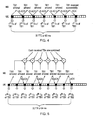
- Figure 4 illustrates schematically a modification of a data transmission regime according to one embodiment.
- User equipment is operating in a standard 2ms TTI data transmission regime, and thus has a predetermined monitoring period set at the standard 16ms referred to above. Retransmission of any given data packet is scheduled to occur every 8 transmissions as necessary.
- the base station If user equipment fails to meet the Quality of Service target time for successful transmission, and the user equipment indicates to the base station that it is not able to transmit the data packets at a higher power due to power limitations, the base station sends a message to the user equipment modifying the data transmission regime.
- the base station indicates to the user equipment that it can reduce the simultaneous HARQ processes to 5.
- the base station also indicates to the user equipment that the power offset is now -1.5dB.
- user equipment On receipt of this information from the base station, user equipment can then calculate the extended number of HARQ transmissions it can now make under the new data transmission regime.
- the user equipment calculates the original Quality of Service target time for successful transmission.
- that time is 64ms (16ms x 4), or 32 TTI.
- the user equipment can also calculate that the monitoring period for receiving an ACK or NACK has been reduced to 5 x TTI, which in this case is 10ms.
- the user equipment can then also calculate that under the new data transmission regime it is possible to fit in 6.4 transmissions to try to meet the same Quality of Service time for successful receipt.
- the number of allowed transmissions is reduced to the nearest whole number. In this example, the number of allowed transmissions is therefore 6.
- the user equipment also acts to calculate a new overall power offset applicable to transmission on the dedicated data channel (E-DPDCH) carrying those data packets.
- E-DPDCH dedicated data channel
- the modified power offset allows the overall power offset to be calculated for the modified data transmission regime as follows:
- the modified data transmission regime is shown schematically in Figure 4 as follows, by considering the transmission of a data packet TB1.
- TB1 is scheduled for transmission every 5 TTI.
- the user equipment received a NACK back from a base station in respect of the first 5 transmissions.
- the sixth transmission of TB1 is, however, successful and user equipment can then place a new data packet in the schedule in place of TB1.
- the total time taken to successfully transmit TB1 is, in this case, 30TTI (60ms) and is still within the target successful transmission time period required to maintain Quality of Service required prior to data transmission regime modification.
- Figure 5 illustrates schematically a modification of a data transmission regime according to a second embodiment.
- the base station processing is not sufficient to match a reduced number of simultaneous HARQ processes, i.e. the base station is unable to ACK or NACK receipt of a data packet before scheduled retransmission of that data packet by user equipment.
- the base station If user equipment fails to meet the Quality of Service target time for successful transmission, and the user equipment indicates to the base station that it is not able to transmit the data packets at a higher power due to power limitations, the base station sends a message to the user equipment modifying the data transmission regime.
- the base station indicates to the user equipment that it can reduce the simultaneous HARQ processes to 4.
- the base station also indicates to the user equipment that the power offset is now -3.0dB.
- user equipment On receipt of this information from the base station, user equipment can then calculate the extended number of HARQ transmissions it can now make under the new data transmission regime.
- the user equipment calculates the original Quality of Service target time for successful transmission.
- that time is 64ms (16ms x 4), or 32 TTI.
- the user equipment can also calculate that the monitoring period for receiving an ACK or NACK has been reduced to 4 x TTI, which in this case is 8ms.
- the user equipment can then also calculate that under the new data transmission regime it is possible to fit in 8 transmissions to try to meet the same Quality of Service target time for successful receipt.
- the user equipment also acts to calculate a new overall power offset applicable to transmission on the dedicated data channel (E-DPDCH) carrying those data packets.
- E-DPDCH dedicated data channel
- the modified power offset allows the overall power offset to be calculated for the modified data transmission regime as follows:
- the base station is unable to complete a HARQ process for a data packet before that data packet is scheduled for retransmission by the user equipment.
- the base station is, however, capable of acknowledging alternate data packet transmissions.
- the modified data transmission regime is shown schematically in Figure 5 in relation to transmission of a data packet TB 1.
- User equipment transmits data packet TB1 and waits for 3TTI's before scheduled retransmission of TB1. In the absence of any acknowledgement from the base station before scheduled retransmission, the user equipment assumes that TB1 was not received by the base station and retransmits TB1 as shown.
- TB1 is retransmitted 7 times after first transmission.
- the data packet TB1 is successfully received by the base station on the 7th transmission (6th retransmission). Since the base station was unable to acknowledge safe receipt before the 8th transmission, user equipment transmits TB18 times. In this example, since the base station is operable to effectively acknowledge alternate data packet transmissions, at most only one additional unnecessary transmission occurs.
- the total time taken to successfully transmit TB1 is, in this case, 32TTI (64ms) and still meets the target successful transmission time period required to maintain Quality of Service required prior to data transmission regime modification.
- FIG. 7 illustrates schematically user equipment operable to perform a method according to one embodiment.
- User equipment 50 comprises: a reception antenna 700, a transmission antenna 710, a data store 715, a power source 725 and a user equipment controller 720.
- the reception antenna 700 is operable to receive transmissions on a radio frequency carrier from a base station.
- Transmission antenna 710 is operable to transmit packets of data on a radio frequency carrier to a base station.
- User equipment controller 720 further comprises: transmission logic 730 operable to transmit a data packet of a predetermined size, over a fixed transmit time interval, at a variable transmission power level to a base station 20; monitoring logic 740 operable to monitor for acknowledgement from the base station of successful receipt of the data packet; and retransmission logic 750 operable to retransmit said data packet if no acknowledgement of successful receipt has been received from a base station after a predetermined monitoring period has elapsed; reception logic 760 operable to receive details of said triggering event, said triggering event comprising receipt of a request to increase said variable transmission power level beyond a predetermined power threshold and said reception logic operable to receive signal from a base station and a power source to determine whether the trigger condition has been met; trigger transmission logic 770 operable to transmit trigger information relating to said triggering event; modification reception logic 780 operable to receive a modification signal generated in response to said triggering information, said modification signal instructing modification of said data transmission regime; and modification implementation logic
- Figure 6 illustrates schematically the main processing steps of one embodiment.
- user equipment as shown in Figure 7 is operable to perform the main processing steps.
- an analogous method may be employed by a base station operating in accordance with another embodiment.
- the components shown schematically in the user equipment of Figure 7 may be employed in a base station in accordance with another embodiment.
- Figure 6 shows the main steps of a data transmission regime: namely transmitting a data packet of a predetermined size, over a fixed transmit time interval, at a variable transmission power level (step 610); monitoring for acknowledgement of successful receipt of the data packet (step 620); and re-transmitting the data packet if no acknowledgement of successful receipt has been received after a predetermined monitoring period has elapsed (step 630).
- transmission logic 730 communicates with data store 715, power source 725 and transmission antenna 710, to send a packet of data to a base station.
- monitoring logic 740 communicates with reception antenna 700, to monitor for an acknowledgement (ACK or NACK) from a base station. Monitoring logic waits for a predetermined monitoring period before communicating with re-transmission logic 750 to schedule re-transmission of the data packet (step 630) via transmission logic 730.
- ACK or NACK acknowledgement
- Figure 6 also illustrates the main processing steps associated with receiving details of a triggering event comprising receipt of a request to increase the variable transmission power level beyond a predetermined power threshold (step 640) and transmission of trigger information relating to the triggering event (step 650).
- step 640 is achieved by trigger reception logic 760 in conjunction with reception antenna 700 and power source 725.
- Base station 20 transmits a request to user equipment 50, asking it to increase power the data packet transmission signal. If reception logic 760 determines that request from the base station cannot be met by power source 725, step 650 is implemented by trigger transmission logic 770.
- Trigger transmission logic operates to transmit details of the trigger event to base station 20, via transmission antenna 710.
- user equipment receives a modification signal generated by the base station 20 in response to the triggering information (sep 660).
- the modification signal instructs modification of the data transmission regime (steps 610, 620 and 630) and the user equipment modifies the data packet transmission regime by decreasing the predetermined monitoring period in accordance with the received modification signal (step 670).
- step 660 is achieved by user equipment 50 by modification logic 780 which receives the modification sent to user equipment 50 and is received by reception antenna 700. That signal is interpreted and step 670 is achieved by modification implementation logic 790 in conjunction with re-transmission logic 750.
- program storage devices e.g., digital data storage media, which are machine or computer readable and encode machine-executable or computer-executable programs of instructions, wherein said instructions perform some or all of the steps of said above-described methods.
- the program storage devices may be, e.g., digital memories, magnetic storage media such as a magnetic disks and magnetic tapes, hard drives, or optically readable digital data storage media.
- the embodiments are also intended to cover computers programmed to perform said steps of the above-described methods.
- processors may be provided through the use of dedicated hardware as well as hardware capable of executing software in association with appropriate software.
- the functions may be provided by a single dedicated processor, by a single shared processor, or by a plurality of individual processors, some of which may be shared.
- processor or “controller” or “logic” should not be construed to refer exclusively to hardware capable of executing software, and may implicitly include, without limitation, digital signal processor (DSP) hardware, network processor, application specific integrated circuit (ASIC), field programmable gate array (FPGA), read only memory (ROM) for storing software, random access memory (RAM), and non volatile storage. Other hardware, conventional and/or custom, may also be included.
- DSP digital signal processor
- ASIC application specific integrated circuit
- FPGA field programmable gate array
- ROM read only memory
- RAM random access memory
- any switches shown in the Figures are conceptual only. Their function may be carried out through the operation of program logic, through dedicated logic, through the interaction of program control and dedicated logic, or even manually, the particular technique being selectable by the implementer as more specifically understood from the context.
- any block diagrams herein represent conceptual views of illustrative circuitry embodying the principles of the invention.
- any flow charts, flow diagrams, state transition diagrams, pseudo code, and the like represent various processes which may be substantially represented in computer readable medium and so executed by a computer or processor, whether or not such computer or processor is explicitly shown.
Landscapes
- Engineering & Computer Science (AREA)
- Computer Networks & Wireless Communication (AREA)
- Signal Processing (AREA)
- Quality & Reliability (AREA)
- Mobile Radio Communication Systems (AREA)
Abstract
Description
- The present invention relates to a method of modifying a data packet transmission regime in a wireless telecommunications network in response to a triggering event, user equipment, a base station and a computer program product.
- Wireless telecommunications systems are known. In those known systems, radio coverage is provided to user equipment, for example, mobile telephones, by regions of geographical area. The required radio coverage in each geographical area may be provided by means of a radio coverage network which may comprise one or more base stations. User equipment located in a geographical area served by a base station receives information and data from the base station and transmits data and information to the base station.
- In a high speed uplink packet access (HSUPA) telecommunications network, data and information is sent between user equipment and a base station in data packets on a radio frequency carrier.
- Packets of data are sent in time blocks of predetermined length. In known wireless telecommunications systems, the available time blocks in a HSUPA network have a length of 10ms or 2ms. Those time blocks are known as data block transmit time intervals (TTI).
- It will be understood that successfully sending a block of data of a given size in a shorter time block (TTI) enables more data to be sent over a given period. However, in order to successfully send a block of data of a given size in a shorter time block, it is necessary to ensure that a radio link is capable of supporting successful data transfer, for example, if may be necessary to ensure signal to noise and interference ratio (SNIR) on the radio frequency carrier is sufficient. In order to achieve a sufficient SNIR, telecommunications equipment (ie a base station or an item of user equipment) will typically need to transmit the data packet on a radio carrier at a higher power for a 2ms transmit time interval than for a 10ms transmit time interval.
- Transmission power available to a base station or user equipment may be limited, for example, to ensure signals are sent at a power level deemed safe for operation, or because a limited amount of power is available from a power source.
- It will therefore be understood that, in a power limited user equipment to base station data transmission scenario, transfer of transport blocks of a given size over a shorter time period (ie operating in a 2ms TTI regime rather than a 10ms TTI regime) may result in a smaller geographical area being adequately supported by radio coverage. Thus, although a 2ms transmit time interval regime can result in higher total data throughput, adequately supporting such a regime may require the provision of more base stations to cover a given geographical area.
- When a power limit is reached, it may be possible for an interaction between user equipment and a base station to be transferred back to a longer transmit time interval regime. Transferring back to a 10ms transmit time interval from a 2ms transmit time interval regime has the advantage that, for a given transport block size, a lower SNIR is required. The required signal to noise and interference ratio is likely to be achievable within the power limitations of the wireless telecommunications system, and the interaction between user equipment and a base station may no longer be operating at the limit of available power. Such an arrangement allows a base station to maintain a larger coverage area, but has the potential disadvantage that outside the area in which 2ms transmit time interval data transmission is available, a user will be forced to operate at the lower data throughput rate offered by a 10ms transmit time interval regime.
- Accordingly, it is desired to provide a modified data transmission regime.
- A first aspect provides a method of modifying a data packet transmission regime in a wireless telecommunications network in response to a triggering event,
the data packet transmission regime comprising: - transmitting a data packet of a predetermined size, over a fixed transmit time interval, at a variable transmission power level;
- monitoring for acknowledgement of successful receipt of the data packet; and re-transmitting the data packet if no acknowledgement of successful receipt has been received after a predetermined monitoring period has elapsed,
- receiving details of the triggering event, the triggering event comprising receipt of a request to increase the variable transmission power level beyond a predetermined power threshold;
- transmitting trigger information relating to the triggering event;
- receiving a modification signal generated in response to the triggering information, the modification signal instructing modification of the data transmission regime; and modifying the data packet transmission regime by decreasing the predetermined monitoring period in accordance with the received modification signal.
- The first aspect recognises that utilising a data transmission regime in which an acknowledgement protocol is operating enables transmission of redundant data packets, or transport blocks of data to be minimised. If a data packet is successfully received and an acknowledgement of successful receipt is received, there is no need to re-send that data packet.
- A method in accordance with the first aspect recognises that repeating transmission of a data packet without knowledge of whether is has successfully reached its destination leads to transmission of redundant data packets and does not optimise overall data throughput in a wireless telecommunications network. It will be appreciated that receipt of a negative acknowledgement, i.e. an indication that the data packet was unsuccessfully received is also considered to be no acknowledgement of successful receipt of a data packet.
- The first aspect further recognises that receiving a request to increase the variable transmission power level beyond a predetermined power threshold can act as a reasonable triggering event. If a request for an increase in power is received, the original operating data transmission regime is not adequately meeting wireless telecommunication network operating targets in some way. If no further power is available for transmission, a different method for attempting to meet operating targets is required.
- Modifying the data packet transmission regime by decreasing the predetermined monitoring period effectively increases the number of retransmissions of a particular data packet. Increasing the number of transmissions, and in particular, retransmitting a particular data packet more often over a particular time period, is likely to result in an improvement to the likelihood that the data packet will be successfully received in that particular time period.
- Repeating transmission of a particular data packet over a period of time increases processing gain of the data packet and can thereby increase coverage area offered in a base station - user equipment interaction in such a wireless telecommunications network.
- In one embodiment, the method further comprises the step of decreasing the transmission power level of the data transmission regime in accordance with the received modification signal.
- Accordingly, compared to a method in which power transmission is not reduced, it is less likely that the modified data transmission regime will cause interference with other transmissions occurring across the wireless telecommunications network.
- Furthermore, since the trigger event indicates that the original data transmission regime was operating near a predetermined power threshold, decreasing the power of transmissions is likely to have the effect of increasing coverage area.
- In one embodiment, the modifying step further comprises the steps of:
- determining for the unmodified data transmission regime, an unmodified power offset;
- determining from the modification signal, a modified power offset; and
- generating a new overall power offset by summing the unmodified power offset and the modified power offset.
- In a user equipment-base station interaction in a wireless telecommunications network user equipment is typically sent signals relating to power offset as opposed to absolute power values. It can therefore be understood that a modification signal relating to reduction of power can be expressed as a change in power offset.
- It will be appreciated that the modification signal may comprise data obtained from a predetermined or pre-mapped look-up table. That table may contain data relating to appropriate reductions in monitoring period and/or power offset values for a data packet of predetermined size.
- In one embodiment, the modifying step further comprises the steps of:
- determining for the unmodified data transmission regime, a target number of total transmissions of the data packet;
- generating a target elapsed time period for the data packet to be successfully received after first transmission of the data packet, by multiplying the target number of total transmission by the unmodified predetermined monitoring period;
- calculating a target number of total transmissions in the modified regime that will fit into the generated target elapsed time by dividing the generated target elapsed time by the modified reduced predetermined monitoring period.
- In a wireless telecommunications network, data relating to various applications is sent from user equipment to a base station and vice versa. It may not be as important to receive all of the packets of data in a simple FTP process quickly as to receive all of the packets of data relating to a voice or video call. A data transmission regime therefore sets a target successful transmission time for a data packet of specific packet size to ensure a user experiences an acceptable quality of service. The target successful transmission time for a specific packet size is also known as Quality of Service (QoS). By considering the quality of service experienced by a user and by targeting the same quality of service in the modified data transmission regime as in the original data transmission regime, it will be understood that compared to a situation in which the data regime is not modified in response to the triggering event, it is more likely that the desired quality of service for a given data packet type will be achieved.
- In one embodiment, the data transmission regime further comprises the steps of monitoring for acknowledgement of partial receipt of the data packet; and retransmitting a modified version of the data packet in response to the acknowledgement of partial receipt of the data packet.
- Accordingly, the first aspect may utilise various means for obtaining processing gain by retransmitting a data packet more frequently than in an unmodified data transmission regime. It will be understood that any partially successfully received data packets may be subjected to a chase combining method or an incremental redundancy method. As a result it may be possible to achieve completely successful receipt of a data packet in a shorter time period, thus requiring fewer retransmissions of any given data packet.
- In one embodiment, the modification signal generated in response to the triggering information comprises an indication of a number of supportable independent consecutive simultaneous acknowledgement processes; and
the step of modifying further comprises a step of calculating a modified predetermined monitoring period by multiplying the indication of a number of supportable simultaneous acknowledgement processes by the fixed transmit time interval; and modifying the data packet transmission regime by setting the predetermined monitoring period in accordance with the calculated modified predetermined monitoring period. - It will be appreciated that a reduced predetermined monitoring period may be calculated from a signal relating to other characteristic of the data transmission regime, such as am indication of a number of supportable simultaneous acknowledgement processes.
- In one embodiment, said fixed transmit time interval is 2ms or 10ms. Accordingly, it will be understood that the first aspect is particularly useful with respect to known used transmit time intervals in wireless telecommunications networks.
- In one embodiment, the unmodified predetermined monitoring period is 16ms or 40ms. It will be appreciated that a standard predetermined monitoring period may be employed in the unmodified data transmission regime.
- In one embodiment, the data packet transmission regime comprises a regime for transmitting data packets from user equipment to a base station.
- In one embodiment, the data packet transmission regime comprises a regime for transmitting data packets from a base station to user equipment.
- In one embodiment, the step of transmitting trigger information relating to the triggering event comprises a step of transmitting trigger information to the base station, and wherein the step of receiving a modification signal generated in response to the triggering information comprises a step of receiving the modification signal from the base station.
- A second aspect provides a computer program product, operable when executed on a computer, to perform the method steps of the first aspect.
- A third aspect provides user equipment operable to modify a data packet transmission regime in a wireless telecommunications network in response to a triggering event, said user equipment comprising:
- transmission logic operable to transmit a data packet of a predetermined size, over a fixed transmit time interval, at a variable transmission power level;
- monitoring logic operable to monitor for acknowledgement of successful receipt of said data packet; and
- retransmission logic operable to retransmit said data packet if no acknowledgement of successful receipt has been received after a predetermined monitoring period has elapsed,
- reception logic operable to receive details of said triggering event, said triggering event comprising receipt of a request to increase said variable transmission power level beyond a predetermined power threshold;
- trigger transmission logic operable to transmit trigger information relating to said triggering event;
- modification reception logic operable to receive a modification signal generated in response to said triggering information, said modification signal instructing modification of said data transmission regime; and
- modification logic operable to modify said data packet transmission regime by decreasing said predetermined monitoring period in accordance with said received modification signal.
- It will be appreciated that the method of the first aspect has particular advantages when implemented in user equipment for use in a wireless telecommunications network. In particular, it will be appreciated that user equipment operable to perform the method steps of the first aspect may be operable to achieve a greater geographical coverage, whilst maintaining performance and overall data throughput in interactions with a suitable base station.
- In one embodiment, the modification logic is further operable to decrease the transmission power level of the data transmission regime in accordance with the received modification signal.
- In one embodiment, the modification logic is further operable to:
- determine for the unmodified data transmission regime, an unmodified power offset;
- determine from the modification signal, a modified power offset; and
- generate a new overall power offset by summing the unmodified power offset and the modified power offset.
- In one embodiment, the modifying logic is further operable to:
- determine for the unmodified data transmission regime, a target number of total transmissions of the data packet;
- generate a target elapsed time period for the data packet to be successfully received after first transmission of the data packet, by multiplying the target number of total transmission by the unmodified predetermined monitoring period;
- calculate a target number of total transmissions in the modified regime that will fit into the generated target elapsed time by dividing the generated target elapsed time by the modified reduced predetermined monitoring period.
- In one embodiment, the monitoring logic is further operable to monitor for acknowledgement of partial receipt of the data packet; and the transmission logic is further operable to retransmit a modified version of the data packet in response to the acknowledgement of partial receipt of the data packet.
- In one embodiment, the modification signal generated in response to the triggering information comprises an indication of a number of supportable simultaneous acknowledgement processes; and the modifying step further comprises a step of calculating a modified predetermined monitoring period by multiplying the indication of a number of supportable simultaneous acknowledgement processes by the fixed transmit time interval; and modifying the data packet transmission regime by setting the predetermined monitoring period in accordance with the calculated modified predetermined monitoring period.
- In one embodiment, the fixed transmit time interval is 2ms or 10ms.
- In one embodiment, the unmodified predetermined monitoring period is 16ms or 40ms.
- In one embodiment, the data packet transmission regime comprises a regime for transmitting data packets from the user equipment to a base station.
- In one embodiment, the step of transmitting trigger information relating to the triggering event comprises: a step of transmitting trigger information to the base station, and wherein the step of receiving a modification signal generated in response to the triggering information comprises a step of receiving the modification signal from the base station.
- A fourth aspect provides a base station operable to modify a data packet transmission regime in a wireless telecommunications network in response to a triggering event, said base station comprising:
- transmission logic operable to transmit a data packet of a predetermined size, over a fixed transmit time interval, at a variable transmission power level;
- monitoring logic operable to monitor for acknowledgement of successful receipt of said data packet; and
- retransmission logic operable to retransmit said data packet if no acknowledgeme nt of successful receipt has been received after a predetermined monitoring period has elapsed,
- reception logic operable to receive details of said triggering event, said triggering event comprising receipt of a request to increase said variable transmission power level beyond a predetermined power threshold;
- trigger transmission logic operable to transmit trigger information relating to said triggering event;
- modification reception logic operable to receive a modification signal generated in response to said triggering information, said modification signal instructing modification of said data transmission regime; and
- modification logic operable to modify said data packet transmission regime by decreasing said predetermined monitoring period in accordance with said received modification signal.
- It will be appreciated that the method of the first aspect may also be implemented by a base station for use in a wireless telecommunications system. A base station may also be power limited and thus may also achieve greater coverage by modifying a data transmission regime having a fixed TTI by employing a modification according to the method of the first aspect.
- In one embodiment, the modification logic is further operable to decrease the transmission power level of the data transmission regime in accordance with the received modification signal.
- In one embodiment, the modification logic is further operable to:
- determine for the unmodified data transmission regime, an unmodified power offset;
- determine from the modification signal, a modified power offset; and
- generate a new overall power offset by summing the unmodified power offset and the modified power offset.
- In one embodiment, the modifying logic is further operable to:
- determine for the unmodified data transmission regime, a target number of total transmissions of the data packet;
- generate a target elapsed time period for the data packet to be successfully received after first transmission of the data packet, by multiplying the target number of total transmission by the unmodified predetermined monitoring period;
- calculate a target number of total transmissions in the modified regime that will fit into the generated target elapsed time by dividing the generated target elapsed time by the modified reduced predetermined monitoring period.
- In one embodiment, the monitoring logic is further operable to monitor for acknowledgement of partial receipt of the data packet; and the transmission logic is further operable to retransmit a modified version of the data packet in response to the acknowledgement of partial receipt of the data packet.
- In one embodiment, the modification signal generated in response to the triggering information comprises an indication of a number of supportable simultaneous acknowledgement processes; and the modifying step further comprises a step of calculating a modified predetermined monitoring period by multiplying the indication of a number of supportable simultaneous acknowledgement processes by the fixed transmit time interval; and modifying the data packet transmission regime by setting the predetermined monitoring period in accordance with the calculated modified predetermined monitoring period.
- In one embodiment, the fixed transmit time interval is 2ms or 10ms.
- In one embodiment, the unmodified predetermined monitoring period is 16ms or 40ms.
- Further particular and preferred aspects of the present invention are set out in the accompanying independent and dependent claims. Features of the dependent claims may be combined with features of the independent claims as appropriate and in combinations other than those explicitly set out in the claims.
- Embodiments of the present invention will now be described further, with reference to the drawings in which:
-
Figure 1 illustrates the main components of a telecommunications network according to one embodiment; -
Figure 2 illustrates schematically a data transmission acknowledgement protocol; -
Figure 3 illustrates schematically a data transmission regime using the data transmission acknowledgement protocol ofFigure 2 ; -
Figure 4 illustrates a modification of a data transmission regime according to one embodiment; -
Figure 5 illustrates a modification of a data transmission regime according to a second embodiment; -
Figure 6 illustrates schematically the main processing steps of one embodiment; and -
Figure 7 illustrates schematically user equipment operable to perform a method according to one embodiment. -
Figure 1 illustrates awireless telecommunications system 10 according to one embodiment.User equipment 50 roam through the wireless telecommunications system.Base stations 20 are provided which support areas ofradio coverage 30. A number ofsuch base stations 20 are provided and are distributed geographically in order to provide a wide area of coverage touser equipment 50. When user equipment is within an area served by abase station 30, communications may be established between the user equipment and the base station over associated radio links. Each base station typically supports a number of sectors within the geographical area ofservice 30. - Typically a different antenna within a base station supports each associated sector. Accordingly, each
base station 20 has multiple antennas and signals sent through the different antennas are electronically weighted to provide a sectorised approach. Of course, it will be appreciated thatFigure 1 illustrates a small subset of the total number of user equipment and base stations that may be present in a typical communications system. - The wireless communications system is managed by a radio network controller (RNC) 40. The
radio network controller 40 controls operation of the wireless communications system by communicating with a plurality of base stations over a backhaul communications link 60. The network controller also communicates withuser equipment 50 via each base station and thus effectively manages the entire wireless communications system. - A
radio network controller 60 maintains a neighbour list which includes information about geographical relationships between sectors supported bybase stations 20. In addition, theradio network controller 60 maintains location information which provides information on the location ofuser equipment 50 within thewireless communication system 10. The radio network controller is operable to route traffic via circuit switched and packet switched networks. Hence, a mobile switching centre is provided with which the radio network controller may communicate. The mobile switching centre can communicate with a circuit switched network such as a public switched telephone network (PSTN) 70. Similarly, a network controller can communicate with service general package radio service support nodes (SGSNs) and a gateway general packet support node (GGSN). The GGSN can communicate with a packet switched core such as for example, the Internet. -
User equipment 50 typically transmits information and data to abase station 20 so that it can be re-routed within a wireless telecommunications network. User equipment may, for example, need to transmit data to the base station in order to relay text messages, voice information when a user is using the equipment to make a telephone call, or other data. Thebase station 20, in combination with parameters set by theradio network controller 40, allocates resource to user equipment in a manner that aims to optimise operation of thewireless telecommunications network 10. - In a high speed uplink packet access (HSUPA) telecommunications network, data and information is sent between user equipment and a base station in data packets on a radio frequency carrier.
- Packets of data are sent in time blocks of predetermined length. In known wireless telecommunications systems, the available time blocks have a length of 10ms or 2ms. Those time blocks are known as data block transmit time intervals (TTI).
- It will be understood that successfully sending a block of data of a given size in a shorter time block (TTI) enables more data to be sent over a given period. However, in order to successfully send a block of data of a given size in a shorter time block, it is necessary to ensure that signal to noise and interference ratio (SNIR) on the radio frequency carrier is sufficient. In order to achieve a sufficient SNIR, telecommunications equipment (i.e. a base station or an item of user equipment) will typically need to transmit the data packet on a radio carrier at a higher power for a 2ms transmit time interval than for a 10ms transmit time interval.
- Transmission power available to a base station or user equipment may be limited, for example, to ensure signals are sent at a power level deemed safe for operation, or because a limited amount of power is available form a power source.
- It will therefore be understood that, in a power limited user equipment - base station data transmission scenario, transfer of transport blocks of a given size over a shorter time period (i.e. operating in a 2ms TTI regime rather than a 10ms TTI regime) may result in a smaller geographical area being adequately supported by radio coverage. Thus, although a 2ms transmit time interval regime can result in higher total data throughput, adequately supporting such a regime may require the provision of more base stations to cover a given geographical area.
-
Figure 2 illustrates schematically a data transmission acknowledgement protocol used in a data transmission regime of atelecommunications network 10. In particular,Figure 2 illustrates schematically transmission of a transport block in a data packet fromuser equipment 50 to abase station 20 in a HSUPA network operating in a 2ms TTI regime and the operation of an acknowledgement protocol known as a Hybrid Automatic Repeat Request (HARQ). HARQ enables fast acknowledgement and consequently fast retransmission of a data packet if required. InFigure 2 , a firstdata packet TB 1 is transmitted from user equipment and successfully received bybase station 20. The base station, in accordance with the HARQ process, sends an acknowledgement of safe receipt (ACK) of TB1 back touser equipment 50.Figure 2 illustrates a "stop and wait" HARQ protocol in which user equipment waits for acknowledgement of safe receipt of a data packet before sending the next. Since a successful receipt is received in respect of TB1, within a pre-programmed monitoring period, user equipment can transmit a second data packet, TB2. The monitoring period in the case shown inFigure 2 is 8 transmit time intervals, i.e. 16ms. - TB2 is not successfully received at
base station 20 and thus the base station generates and sends a negative acknowledgement (NACK). After waiting the pre-programmed monitoring period and having received a NACK, user equipment retransmits TB2, which is then received successfully by the base station. -
Figure 3 illustrates schematically a data transmission regime using the data transmission acknowledgement protocol ofFigure 2 . In a HSUPA telecommunications network a synchronous HARQ protocol is used. In such a case, retransmission of a given data packet is expected after a pre-programmed monitoring period. That pre-programmed monitoring period is the time between commencement of two transmissions of the same packet of data and has been set in accordance with a reasonable estimate of operative HARQ round trip time. The estimate of HARQ round trip time for 2ms TTI and predetermined monitoring period for the 2ms TTI regime has been set at 8TTI (16ms). - Whilst waiting for an ACK or NACK from a base station in respect of a given data packet, user equipment can transmit further data packets. The base station can also monitor for successful receipt or otherwise of those data packets and it will thus be understood that there are, at most, 8 simultaneous HARQ processes occurring at any given time.
- A data transmission regime using a monitoring period of 16ms is shown. In the case illustrated, eight data packets, labelled as TB1 to TB8 are consecutively transmitted by user equipment, one in each 2ms TTI. Each data packet is subject to a HARQ process, labelled as "HARQ Pro1" to "HARQ Pro8". As shown, TB1, TB3, TB4, TB5, TB6 and TB8 are not successfully received by the
base station 20 and they are retransmitted in the next sequence of 8 transmitted data packets in the TTI's shown. Since TB2 and TB7, transmitted in HARQ Pro2 and HARQ Pro7 respectively, are successfully received and acknowledged bybase station 20, in the next sequence of 8 transmitted data packets two new data packets TB9 and TB10 respectively, can be transmitted onHARQ Pro 2 and HARQ Pro7. - For a given application (for example, voice data, video data or an FTP process)
user equipment 50 andbase station 20 are aware, via a look up table, that successful reception of a transmitted data packet of a particular size within a target elapsed time period after first transmission will result in a good service experience by a user. That target elapsed time period will depend upon the application being offered. The target elapsed time period for video or voice, for example, will typically be significantly shorter than the target elapsed time for a data packet relating to a SMS message. The target elapsed time period for a data packet of a given size for a given size of data packet is referred to as "Quality of Service". -
User equipment 50 andbase station 20 may each have a look up table, giving an initial starting set of parameters within whichuser equipment 50 can operate for transmission of a data packet, or transport block, of given size for a given application. That look up table is known as a HARQ profile. The HARQ profile specifies a power offset and a number of maximum transmissions (including a first transmission) for a data packet of given size, for a particular application, requiring a particular Quality of Service. - Use of the HARQ protocol in combination with a Quality of Service target allows calculation of some indication of whether user equipment and base station are operating to offer an acceptable level of service to an end user.
- It will be understood that to meet a Quality of Service target, each data packet has a target number of retransmissions. The maximum number of transmissions includes the first transmission and all subsequent retransmissions of the same data packet. If a data packet transmitted by user equipment is not successfully received by a base station after the maximum number of transmissions has been made, it is deemed to have failed and a higher level retransmission at the Radio Link Control level is performed. RLC retransmission is slow and thus undesirable. In practical terms, if a data transmission between user equipment and a base station is not meeting a required quality of service, the base station indicates to user equipment that it needs to increase the power at which it is transmitting those data packets. It will be understood that increasing the power of transmission of a data packet increases the SNIR and thus increases the chances that data packet will be successfully received by a base station within the Quality of Service target time.
- For a data packet of a particular size, the larger the number of transmissions allowed by the HARQ Profile, the lower the transmit power required from user equipment when transmitting that data packet. It will be understood that, as a result of the HARQ protocol employed, a base station will be able to terminate retransmission of a data packet if the data packet is successfully received by the base station before the maximum number of transmissions set in the HARQ profile is reached. Early termination of that process results in user equipment achieving a higher total data throughput.
- A Retransmission Sequence Number (RSN) is used to monitor how often a given data packet is transmitted. As described above, a radio carrier comprises a plurality of channels. A channel upon which data packets are sent from user equipment to a base station relating to user equipment applications (for example, voice, video, SMS) are sent is known as an E-DCH Dedicated Physical Data Channel (E-DPDCH). A channel upon which control information relating to the user equipment is sent is known as an E-DCH Dedicated Physical Control Channel (E-DPCCH). The RSN is sent on the E-DPCCH channel together with the data packet sent on the data channel. A known specification for HSUPA networks allows 2 bits for the RSN. However, the maximum number of transmissions is not limited to 4. Nonetheless, this is not a hindrance, since the RSN does not need to increase for transmissions beyond 4. Furthermore, the existing HARQ profile table allows up to 16 transmissions to meet a particular Quality of Service.
- It has been recognised that in a power limited scenario, user equipment and base stations may be unable to meet a given Quality of Service target time by simply increasing power of transmission as described above. If a Quality of Service target is not being met, a message may be sent to up the power of transmission, and if a power threshold has been met, there may be no further power available.
- It has been recognised that it is possible to employ the HARQ protocol in a modified data transmission regime in such a power limited situation, such that the number of redundant data packets transmitted is minimised and such that the target time required to achieve a given Quality of Service may still be met.
- In known systems utilising the HARQ protocol, as described above, retransmission of a given data packet is expected after a pre-programmed monitoring period. That pre-programmed monitoring period is the time between commencement of two transmissions of the same packet of data and has been fixed in accordance with a reasonable estimate of operative HARQ round trip time. The estimate of HARQ round trip time for 2ms TTI and predetermined monitoring period for the 2ms TTI regime has been set at a fixed 8TTI (16ms).
- It has been recognised that if the pre-programmed monitoring period is reduced, it is possible to fit more transmission of a given data packet into a Quality of Service target time. This may result in a data packet being successfully received within the Quality of Service target time and thus the Quality of Service being met. Furthermore, repetition of a data packet, as allowed by a greater number of retransmissions, increases the processing gain of a data packet (for example, by chase combining or by incremental redundancy) and thus increases coverage of a base station-user equipment interaction.
- It will be understood that it is possible for user equipment or a base station to conduct more transmissions of a data packet under this modified transmission regime at full, or close to full, power. That may, however, cause interference to other users. It has been recognised that decreasing the monitoring period and thus allowing for a greater number of transmissions also allows the transmit power required to send a given data packet to be lowered, thereby further increasing the coverage offered by a base station-user equipment interaction.
- In one embodiment,
user equipment 20 is transmitting packets of data to abase station 20 in a 2ms TTI data transmission regime. User equipment operates as described in relation toFigures 2 and 3 , aiming to meet a known Quality of Service. Ifuser equipment 50 indicates to a base station that it has reached a predetermined power threshold,base station 20 is operable to send a signal (for example via HS-SCCH) touser equipment 50, instructing that user equipment to reduce the number of simultaneous ongoing HARQ processes from the standard 8 in the 2ms TTI regime to a lower number, for example, 6, 5, 4 or 3. As a result, the user equipment can calculate that the monitoring period for acknowledgement of successful receipt of said data packet, and the retransmission wait for a data packet is reduced. - Since the user equipment was operating to a known Quality of Service target successful transmission time before it reached a power limit trigger event, the user equipment can calculate how many transmissions it is allowed under the new regime whilst still aiming to meet the same Quality of Service target successful transmission time.
- In this embodiment, the
base station 20 is also operable to send a power offset touser equipment 50.User equipment 50 applies that power offset in addition to the power offset specified by the HARQ profile look up table, when transmitting data packets of an uplink data channel. - In one embodiment, the base station will be operable to complete a HARQ protocol for a data packet and return an ACK or a NACK before the time slot allocated by
user equipment 20 for retransmission of that data packet. It may, however, be possible that an older base station will not capable of processing the HARQ request quickly enough to meet that target. In that instance, the base station may only reduce the nu mber of simultaneous HARQ processes (and thus ACK/NACK receipt monitoring period) to a time period which the base station can handle. Alternatively, a base station can choose not to acknowledge specific data packet transmissions, for example alternate data packet transmissions in a sequence. In this case, a base station can may particular use of a store and process capability. Data packets received, even unsuccessfully can be combined (by chase or incremental redundancy). At the user equipment, an unacknowledged data packet will be assumed to have failed to be successfully received when the reduced monitoring period expires. As a result, the user equipment retransmits that data packet in the next HARQ process assigned to that data packet. - Use of a modified data transmission scheme as described above allows use of incremental redundancy which offers higher gain than simple pure repetition of transmission of a data packet. Furthermore, use of the HARQ process minimises transmission of unnecessary data packets. Since the HARQ process demands retransmission of a data packet in a spaced TTI, use of the HARQ protocol allows time diversity to be leveraged, which is particularly useful in a high Doppler environment. As a result of these factors, a data packet of a predetermined size can have a larger overall throughput, due to early termination enabled by the HARQ protocol and/or processing gain if, for example, it is transmitted via 5 HARQ transmissions in a 2ms TTI regime compared to transmission of that same data packet in one transmission in a 10ms TTI regime, even though both have the same overall transmission time.
- It will therefore be understood that implementation of a modified data transmission 2ms TTI regime as described herein can allow for: an increase in geographical coverage, a maintenance of Quality of Service and an increase of data throughput compared to simply transferring to a 10ms TTI regime.
-
Figure 4 illustrates schematically a modification of a data transmission regime according to one embodiment. User equipment is operating in a standard 2ms TTI data transmission regime, and thus has a predetermined monitoring period set at the standard 16ms referred to above. Retransmission of any given data packet is scheduled to occur every 8 transmissions as necessary. In this standard scheme, a data packet of a predetermined size is tied to a particular Quality of Service having the following HARQ profile: maximum number of transmissions = 4, power offset 2dB. It can be calculated that the Quality of Service target time for successful transmission is 64ms (16ms x 4). - If user equipment fails to meet the Quality of Service target time for successful transmission, and the user equipment indicates to the base station that it is not able to transmit the data packets at a higher power due to power limitations, the base station sends a message to the user equipment modifying the data transmission regime.
- In the embodiment shown, the base station indicates to the user equipment that it can reduce the simultaneous HARQ processes to 5. The base station also indicates to the user equipment that the power offset is now -1.5dB.
- On receipt of this information from the base station, user equipment can then calculate the extended number of HARQ transmissions it can now make under the new data transmission regime.
- In particular, the user equipment calculates the original Quality of Service target time for successful transmission. In this case, as described above, that time is 64ms (16ms x 4), or 32 TTI.
- Since the number of simultaneous HARQ processes has been reduced by the base station to 5, the user equipment can also calculate that the monitoring period for receiving an ACK or NACK has been reduced to 5 x TTI, which in this case is 10ms.
- The user equipment can then also calculate that under the new data transmission regime it is possible to fit in 6.4 transmissions to try to meet the same Quality of Service time for successful receipt. The number of allowed transmissions is reduced to the nearest whole number. In this example, the number of allowed transmissions is therefore 6.
- The user equipment also acts to calculate a new overall power offset applicable to transmission on the dedicated data channel (E-DPDCH) carrying those data packets.
- The modified power offset allows the overall power offset to be calculated for the modified data transmission regime as follows:
- Overall power offset = original power offset + power offset in modified regime
- 0.5dB = 2dB - 1.5dB
- The modified data transmission regime is shown schematically in
Figure 4 as follows, by considering the transmission of a data packet TB1. TB1 is scheduled for transmission every 5 TTI. In the example illustrated, the user equipment received a NACK back from a base station in respect of the first 5 transmissions. The sixth transmission of TB1 is, however, successful and user equipment can then place a new data packet in the schedule in place of TB1. The total time taken to successfully transmit TB1 is, in this case, 30TTI (60ms) and is still within the target successful transmission time period required to maintain Quality of Service required prior to data transmission regime modification. -
Figure 5 illustrates schematically a modification of a data transmission regime according to a second embodiment. - In this embodiment the base station processing is not sufficient to match a reduced number of simultaneous HARQ processes, i.e. the base station is unable to ACK or NACK receipt of a data packet before scheduled retransmission of that data packet by user equipment.
- For simplicity, the user operates in standard 2ms TTI identically to the embodiment described in
Figure 4 . That is to say the HARQ profile of standard operation is: maximum number of transmissions = 4, power offset = 2dB. As calculated previously, the Quality of Service target time for successful transmission is 32TTI (64ms). - If user equipment fails to meet the Quality of Service target time for successful transmission, and the user equipment indicates to the base station that it is not able to transmit the data packets at a higher power due to power limitations, the base station sends a message to the user equipment modifying the data transmission regime.
- In the embodiment shown, the base station indicates to the user equipment that it can reduce the simultaneous HARQ processes to 4. The base station also indicates to the user equipment that the power offset is now -3.0dB.
- On receipt of this information from the base station, user equipment can then calculate the extended number of HARQ transmissions it can now make under the new data transmission regime.
- In particular, the user equipment calculates the original Quality of Service target time for successful transmission. In this case, as described above, that time is 64ms (16ms x 4), or 32 TTI.
- Since the number of simultaneous HARQ processes has been reduced by the base station to 4, the user equipment can also calculate that the monitoring period for receiving an ACK or NACK has been reduced to 4 x TTI, which in this case is 8ms.
- The user equipment can then also calculate that under the new data transmission regime it is possible to fit in 8 transmissions to try to meet the same Quality of Service target time for successful receipt.
- The user equipment also acts to calculate a new overall power offset applicable to transmission on the dedicated data channel (E-DPDCH) carrying those data packets.
- The modified power offset allows the overall power offset to be calculated for the modified data transmission regime as follows:
- Overall power offset = original power offset + power offset in modified regime
- -1.0dB = 2dB - 3.0dB
- In this embodiment, the base station is unable to complete a HARQ process for a data packet before that data packet is scheduled for retransmission by the user equipment. The base station is, however, capable of acknowledging alternate data packet transmissions.
- The modified data transmission regime is shown schematically in
Figure 5 in relation to transmission of adata packet TB 1. User equipment transmits data packet TB1 and waits for 3TTI's before scheduled retransmission of TB1. In the absence of any acknowledgement from the base station before scheduled retransmission, the user equipment assumes that TB1 was not received by the base station and retransmits TB1 as shown. - As shown in
Figure 5 , TB1 is retransmitted 7 times after first transmission. The data packet TB1 is successfully received by the base station on the 7th transmission (6th retransmission). Since the base station was unable to acknowledge safe receipt before the 8th transmission, user equipment transmits TB18 times. In this example, since the base station is operable to effectively acknowledge alternate data packet transmissions, at most only one additional unnecessary transmission occurs. - The total time taken to successfully transmit TB1 is, in this case, 32TTI (64ms) and still meets the target successful transmission time period required to maintain Quality of Service required prior to data transmission regime modification.
-
Figure 7 illustrates schematically user equipment operable to perform a method according to one embodiment.User equipment 50 comprises: areception antenna 700, atransmission antenna 710, adata store 715, apower source 725 and auser equipment controller 720. Thereception antenna 700 is operable to receive transmissions on a radio frequency carrier from a base station.Transmission antenna 710 is operable to transmit packets of data on a radio frequency carrier to a base station. -
User equipment controller 720 further comprises:transmission logic 730 operable to transmit a data packet of a predetermined size, over a fixed transmit time interval, at a variable transmission power level to abase station 20; monitoring logic 740 operable to monitor for acknowledgement from the base station of successful receipt of the data packet; andretransmission logic 750 operable to retransmit said data packet if no acknowledgement of successful receipt has been received from a base station after a predetermined monitoring period has elapsed;reception logic 760 operable to receive details of said triggering event, said triggering event comprising receipt of a request to increase said variable transmission power level beyond a predetermined power threshold and said reception logic operable to receive signal from a base station and a power source to determine whether the trigger condition has been met; triggertransmission logic 770 operable to transmit trigger information relating to said triggering event; modification reception logic 780 operable to receive a modification signal generated in response to said triggering information, said modification signal instructing modification of said data transmission regime; and modification implementation logic - 790 operable to modify said data packet transmission regime by decreasing said predetermined monitoring period in accordance with said received modification signal.
-
Figure 6 illustrates schematically the main processing steps of one embodiment. In the embodiment shown inFigure 6 user equipment as shown inFigure 7 is operable to perform the main processing steps. It will be understood that an analogous method may be employed by a base station operating in accordance with another embodiment. It will further be appreciated that the components shown schematically in the user equipment ofFigure 7 may be employed in a base station in accordance with another embodiment. -
Figure 6 shows the main steps of a data transmission regime: namely transmitting a data packet of a predetermined size, over a fixed transmit time interval, at a variable transmission power level (step 610); monitoring for acknowledgement of successful receipt of the data packet (step 620); and re-transmitting the data packet if no acknowledgement of successful receipt has been received after a predetermined monitoring period has elapsed (step 630). - To implement
step 610transmission logic 730 communicates withdata store 715,power source 725 andtransmission antenna 710, to send a packet of data to a base station. To implementstep 620, monitoring logic 740 communicates withreception antenna 700, to monitor for an acknowledgement (ACK or NACK) from a base station. Monitoring logic waits for a predetermined monitoring period before communicating withre-transmission logic 750 to schedule re-transmission of the data packet (step 630) viatransmission logic 730. -
Figure 6 also illustrates the main processing steps associated with receiving details of a triggering event comprising receipt of a request to increase the variable transmission power level beyond a predetermined power threshold (step 640) and transmission of trigger information relating to the triggering event (step 650). - Implementation of
step 640 is achieved bytrigger reception logic 760 in conjunction withreception antenna 700 andpower source 725.Base station 20 transmits a request touser equipment 50, asking it to increase power the data packet transmission signal. Ifreception logic 760 determines that request from the base station cannot be met bypower source 725,step 650 is implemented bytrigger transmission logic 770. Trigger transmission logic operates to transmit details of the trigger event tobase station 20, viatransmission antenna 710. - If a trigger notification is sent, user equipment receives a modification signal generated by the
base station 20 in response to the triggering information (sep 660). The modification signal instructs modification of the data transmission regime (steps - Implementation of
step 660 is achieved byuser equipment 50 by modification logic 780 which receives the modification sent touser equipment 50 and is received byreception antenna 700. That signal is interpreted and step 670 is achieved bymodification implementation logic 790 in conjunction withre-transmission logic 750. - A person of skill in the art would readily recognize that steps of various above-described methods can be performed by programmed computers. Herein, some embodiments are also intended to cover program storage devices, e.g., digital data storage media, which are machine or computer readable and encode machine-executable or computer-executable programs of instructions, wherein said instructions perform some or all of the steps of said above-described methods. The program storage devices may be, e.g., digital memories, magnetic storage media such as a magnetic disks and magnetic tapes, hard drives, or optically readable digital data storage media. The embodiments are also intended to cover computers programmed to perform said steps of the above-described methods.
- The functions of the various elements shown in the Figures, including any functional blocks labelled as "processors" or "logic", may be provided through the use of dedicated hardware as well as hardware capable of executing software in association with appropriate software. When provided by a processor, the functions may be provided by a single dedicated processor, by a single shared processor, or by a plurality of individual processors, some of which may be shared. Moreover, explicit use of the term "processor" or "controller" or "logic" should not be construed to refer exclusively to hardware capable of executing software, and may implicitly include, without limitation, digital signal processor (DSP) hardware, network processor, application specific integrated circuit (ASIC), field programmable gate array (FPGA), read only memory (ROM) for storing software, random access memory (RAM), and non volatile storage. Other hardware, conventional and/or custom, may also be included. Similarly, any switches shown in the Figures are conceptual only. Their function may be carried out through the operation of program logic, through dedicated logic, through the interaction of program control and dedicated logic, or even manually, the particular technique being selectable by the implementer as more specifically understood from the context.
- It should be appreciated by those skilled in the art that any block diagrams herein represent conceptual views of illustrative circuitry embodying the principles of the invention. Similarly, it will be appreciated that any flow charts, flow diagrams, state transition diagrams, pseudo code, and the like represent various processes which may be substantially represented in computer readable medium and so executed by a computer or processor, whether or not such computer or processor is explicitly shown.
- The description and drawings merely illustrate the principles of the invention. It will thus be appreciated that those skilled in the art will be able to devise various arrangements that, although not explicitly described or shown herein, embody the principles of the invention and are included within its spirit and scope. Furthermore, all examples recited herein are principally intended expressly to be only for pedagogical purposes to aid the reader in understanding the principles of the invention and the concepts contributed by the inventor(s) to furthering the art, and are to be construed as being without limitation to such specifically recited examples and conditions. Moreover, all statements herein reciting principles, aspects, and embodiments of the invention, as well as specific examples thereof, are intended to encompass equivalents thereof.
Claims (13)
- A method of modifying a data packet transmission regime in a wireless telecommunications network in response to a triggering event,
said data packet transmission regime comprising:transmitting a data packet of a predetermined size, over a fixed transmit time interval, at a variable transmission power level;monitoring for acknowledgement of successful receipt of said data packet; andretransmitting said data packet if no acknowledgement of successful receipt has been received after a predetermined monitoring period has elapsed,receiving details of said triggering event, said triggering event comprising receipt of a request to increase said variable transmission power level beyond a predetermined power threshold;transmitting trigger information relating to said triggering event;receiving a modification signal generated in response to said triggering information, said modification signal instructing modification of the data transmission regime; andmodifying said data packet transmission regime by decreasing said predetermined monitoring period in accordance with said received modification signal. - A method of modifying a data packet transmission regime according to claim 1, further comprising the step of:decreasing said transmission power level of said data transmission regime in accordance with said received modification signal.
- A method of modifying a data packet transmission regime according to claim 1 or claim 2, wherein said modifying step further comprises the steps of:determining for the unmodified data transmission regime, an unmodified power offset;determining from said modification signal, a modified power offset; andgenerating a new overall power offset by summing said unmodified power offset and said modified power offset.
- A method of modifying a data packet transmission regime according to any preceding claim, wherein said modifying step further comprises the steps of:determining for the unmodified data transmission regime, a target number of total transmissions of said data packet;generating a target elapsed time period for said data packet to be successfully received after first transmission of said data packet, by multiplying said target number of total transmission by said unmodified predetermined monitoring period;calculating a target number of total transmissions in the modified regime that will fit into said generated target elapsed time by dividing said generated target elapsed time by said modified reduced predetermined monitoring period.
- A method of modifying a data packet transmission regime according to any preceding claim, wherein said data transmission regime further comprises the steps of:monitoring for acknowledgement of partial receipt of said data packet; andretransmitting a modified version of said data packet in response to said acknowledgement of partial receipt of said data packet.
- A method of modifying a data packet transmission regime according to any preceding claim, wherein said modification signal generated in response to said triggering information comprises an indication of a number of supportable simultaneous acknowledgement processes; andsaid modifying step further comprises a step of calculating a modified predetermined monitoring period by multiplying said indication of a number of supportable simultaneous acknowledgement processes by said fixed transmit time interval; andmodifying said data packet transmission regime by setting said predetermined monitoring period in accordance with said calculated modified predetermined monitoring period.
- A method of modifying a data packet transmission regime according to any preceding claim, wherein said fixed transmit time interval is 2ms or 10ms.
- A method of modifying a data packet transmission regime according to any preceding claim, wherein said unmodified predetermined monitoring period is 16ms or 40ms.
- A method according to any preceding claim, wherein said data packet transmission regime comprises a regime for transmitting data packets from user equipment to a base station.
- A method according to claim 9, wherein said step of transmitting trigger information relating to said triggering event comprises a step of transmitting trigger information to the base station, and wherein said step of receiving a modification signal generated in response to said triggering information comprises a step of receiving said modification signal from said base station.
- A computer program product, operable when executed on a computer, to perform the method steps of any of claims 1 to 10.
- User equipment operable to modify a data packet transmission regime in a wireless telecommunications network in response to a triggering event, said user equipment comprising:transmission logic operable to transmit a data packet of a predetermined size, over a fixed transmit time interval, at a variable transmission power level;monitoring logic operable to monitor for acknowledgement of successful receipt of said data packet; andretransmission logic operable to retransmit said data packet if no acknowledgement of successful receipt has been received after a predetermined monitoring period has elapsed,reception logic operable to receive details of said triggering event, said triggering event comprising receipt of a request to increase said variable transmission power level beyond a predetermined power threshold;trigger transmission logic operable to transmit trigger information relating to said triggering event;modification reception logic operable to receive a modification signal generated in response to said triggering information, said modification signal instructing modification of said data transmission regime; andmodification logic operable to modify said data packet transmission regime by decreasing said predetermined monitoring period in accordance with said received modification signal.
- A base station operable to modify a data packet transmission regime in a wireless telecommunications network in response to a triggering event, said base station comprising:transmission logic operable to transmit a data packet of a predetermined size, over a fixed transmit time interval, at a variable transmission power level;monitoring logic operable to monitor for acknowledgement of successful receipt of said data packet; andretransmission logic operable to retransmit said data packet if no acknowledgement of successful receipt has been received after a predetermined monitoring period has elapsed,reception logic operable to receive details of said triggering event, said triggering event comprising receipt of a request to increase said variable transmission power level beyond a predetermined power threshold;trigger transmission logic operable to transmit trigger information relating to said triggering event;modification reception logic operable to receive a modification signal generated in response to said triggering information, said modification signal instructing modification of said data transmission regime; andmodification logic operable to modify said data packet transmission regime by decreasing said predetermined monitoring period in accordance with said received modification signal.
Priority Applications (2)
| Application Number | Priority Date | Filing Date | Title |
|---|---|---|---|
| EP20090360040 EP2285033B1 (en) | 2009-08-13 | 2009-08-13 | Modification of data transmission regime |
| PCT/EP2010/004588 WO2011018159A1 (en) | 2009-08-13 | 2010-07-22 | Modification of a data transmission regime |
Applications Claiming Priority (1)
| Application Number | Priority Date | Filing Date | Title |
|---|---|---|---|
| EP20090360040 EP2285033B1 (en) | 2009-08-13 | 2009-08-13 | Modification of data transmission regime |
Publications (2)
| Publication Number | Publication Date |
|---|---|
| EP2285033A1 true EP2285033A1 (en) | 2011-02-16 |
| EP2285033B1 EP2285033B1 (en) | 2012-10-03 |
Family
ID=42027663
Family Applications (1)
| Application Number | Title | Priority Date | Filing Date |
|---|---|---|---|
| EP20090360040 Active EP2285033B1 (en) | 2009-08-13 | 2009-08-13 | Modification of data transmission regime |
Country Status (2)
| Country | Link |
|---|---|
| EP (1) | EP2285033B1 (en) |
| WO (1) | WO2011018159A1 (en) |
Cited By (2)
| Publication number | Priority date | Publication date | Assignee | Title |
|---|---|---|---|---|
| EP2723010A1 (en) * | 2012-10-22 | 2014-04-23 | Fraunhofer-Gesellschaft zur Förderung der angewandten Forschung e.V. | Transmitter and method for transmitting blocks of user data through a channel of variable capacity, a receiver and method for receiving blocks of user data through a channel of variable capacity |
| WO2017136041A1 (en) * | 2016-02-01 | 2017-08-10 | Qualcomm Incorporated | Dynamic adjustment of transmission timeout interval in communication protocols |
Families Citing this family (1)
| Publication number | Priority date | Publication date | Assignee | Title |
|---|---|---|---|---|
| CN106982456B (en) * | 2016-01-15 | 2021-12-31 | 华为技术有限公司 | Communication transmission method, terminal equipment and base station |
Citations (2)
| Publication number | Priority date | Publication date | Assignee | Title |
|---|---|---|---|---|
| EP1727317A1 (en) * | 2004-03-18 | 2006-11-29 | Matsushita Electric Industrial Co., Ltd. | Radio communication device and route search method |
| WO2007125462A2 (en) * | 2006-04-29 | 2007-11-08 | Koninklijke Philips Electronics N.V. | Method and apparatus for controlling energy consumption of sensor network nodes |
-
2009
- 2009-08-13 EP EP20090360040 patent/EP2285033B1/en active Active
-
2010
- 2010-07-22 WO PCT/EP2010/004588 patent/WO2011018159A1/en not_active Ceased
Patent Citations (2)
| Publication number | Priority date | Publication date | Assignee | Title |
|---|---|---|---|---|
| EP1727317A1 (en) * | 2004-03-18 | 2006-11-29 | Matsushita Electric Industrial Co., Ltd. | Radio communication device and route search method |
| WO2007125462A2 (en) * | 2006-04-29 | 2007-11-08 | Koninklijke Philips Electronics N.V. | Method and apparatus for controlling energy consumption of sensor network nodes |
Cited By (2)
| Publication number | Priority date | Publication date | Assignee | Title |
|---|---|---|---|---|
| EP2723010A1 (en) * | 2012-10-22 | 2014-04-23 | Fraunhofer-Gesellschaft zur Förderung der angewandten Forschung e.V. | Transmitter and method for transmitting blocks of user data through a channel of variable capacity, a receiver and method for receiving blocks of user data through a channel of variable capacity |
| WO2017136041A1 (en) * | 2016-02-01 | 2017-08-10 | Qualcomm Incorporated | Dynamic adjustment of transmission timeout interval in communication protocols |
Also Published As
| Publication number | Publication date |
|---|---|
| WO2011018159A1 (en) | 2011-02-17 |
| EP2285033B1 (en) | 2012-10-03 |
Similar Documents
| Publication | Publication Date | Title |
|---|---|---|
| US10708010B2 (en) | Method and apparatus for allocation of physical resources for uplink transmissions | |
| CN101292555B (en) | Select diversity for radio communications | |
| KR101276841B1 (en) | method of triggering status report message in mobile communication system and device implementing the same | |
| KR101343899B1 (en) | Method, system and equipment for processing information | |
| US10142953B2 (en) | Method and apparatus for performing synchronous HARQ operation according to variable TTI allocation | |
| JP2007511135A (en) | Wireless communication method and apparatus for coordinating Node B during handover and supporting Enhanced Uplink transmission | |
| US7693538B2 (en) | Fast hard handover scheme and mobile station and base station supporting such scheme | |
| CN102301798B (en) | Method, System And Device For Enhancing The Uplink Coverage Capacity Of The User Equipment | |
| KR20100069125A (en) | Communication system and method for connecting of rrc therein | |
| EP2328297B1 (en) | Data packet transmission regime modification and notification thereof to a set of active base stations | |
| EP2285033B1 (en) | Modification of data transmission regime | |
| EP2487824A1 (en) | Transmitting data packets between network nodes | |
| WO2010126114A1 (en) | Wireless base station | |
| JP4044904B2 (en) | Packet data retransmission by separate retransmission transmitter | |
| JP5532576B2 (en) | Communication device | |
| EP2262302A1 (en) | Telecommunication method, system and apparatus | |
| WO2025002606A1 (en) | Methods, infrastructure equipment, and communications devices | |
| CN119011091A (en) | Communication method, device and storage medium | |
| KR20070078331A (en) | Method and apparatus for transmitting scheduling information in mobile communication system | |
| HK1100597B (en) | Method and apparatus for implementing a data lifespan timer for enhanced dedicated channel transmissions |
Legal Events
| Date | Code | Title | Description |
|---|---|---|---|
| PUAI | Public reference made under article 153(3) epc to a published international application that has entered the european phase |
Free format text: ORIGINAL CODE: 0009012 |
|
| AK | Designated contracting states |
Kind code of ref document: A1 Designated state(s): AT BE BG CH CY CZ DE DK EE ES FI FR GB GR HR HU IE IS IT LI LT LU LV MC MK MT NL NO PL PT RO SE SI SK SM TR |
|
| AX | Request for extension of the european patent |
Extension state: AL BA RS |
|
| 17P | Request for examination filed |
Effective date: 20110816 |
|
| RAP1 | Party data changed (applicant data changed or rights of an application transferred) |
Owner name: ALCATEL LUCENT |
|
| GRAP | Despatch of communication of intention to grant a patent |
Free format text: ORIGINAL CODE: EPIDOSNIGR1 |
|
| GRAS | Grant fee paid |
Free format text: ORIGINAL CODE: EPIDOSNIGR3 |
|
| GRAA | (expected) grant |
Free format text: ORIGINAL CODE: 0009210 |
|
| AK | Designated contracting states |
Kind code of ref document: B1 Designated state(s): AT BE BG CH CY CZ DE DK EE ES FI FR GB GR HR HU IE IS IT LI LT LU LV MC MK MT NL NO PL PT RO SE SI SK SM TR |
|
| REG | Reference to a national code |
Ref country code: GB Ref legal event code: FG4D |
|
| REG | Reference to a national code |
Ref country code: AT Ref legal event code: REF Ref document number: 578407 Country of ref document: AT Kind code of ref document: T Effective date: 20121015 Ref country code: CH Ref legal event code: EP |
|
| REG | Reference to a national code |
Ref country code: IE Ref legal event code: FG4D |
|
| REG | Reference to a national code |
Ref country code: DE Ref legal event code: R096 Ref document number: 602009010166 Country of ref document: DE Effective date: 20121129 |
|
| REG | Reference to a national code |
Ref country code: AT Ref legal event code: MK05 Ref document number: 578407 Country of ref document: AT Kind code of ref document: T Effective date: 20121003 |
|
| PG25 | Lapsed in a contracting state [announced via postgrant information from national office to epo] |
Ref country code: SI Free format text: LAPSE BECAUSE OF FAILURE TO SUBMIT A TRANSLATION OF THE DESCRIPTION OR TO PAY THE FEE WITHIN THE PRESCRIBED TIME-LIMIT Effective date: 20121003 |
|
| REG | Reference to a national code |
Ref country code: NL Ref legal event code: VDEP Effective date: 20121003 |
|
| REG | Reference to a national code |
Ref country code: LT Ref legal event code: MG4D |
|
| PG25 | Lapsed in a contracting state [announced via postgrant information from national office to epo] |
Ref country code: ES Free format text: LAPSE BECAUSE OF FAILURE TO SUBMIT A TRANSLATION OF THE DESCRIPTION OR TO PAY THE FEE WITHIN THE PRESCRIBED TIME-LIMIT Effective date: 20130114 Ref country code: LT Free format text: LAPSE BECAUSE OF FAILURE TO SUBMIT A TRANSLATION OF THE DESCRIPTION OR TO PAY THE FEE WITHIN THE PRESCRIBED TIME-LIMIT Effective date: 20121003 Ref country code: SE Free format text: LAPSE BECAUSE OF FAILURE TO SUBMIT A TRANSLATION OF THE DESCRIPTION OR TO PAY THE FEE WITHIN THE PRESCRIBED TIME-LIMIT Effective date: 20121003 Ref country code: IS Free format text: LAPSE BECAUSE OF FAILURE TO SUBMIT A TRANSLATION OF THE DESCRIPTION OR TO PAY THE FEE WITHIN THE PRESCRIBED TIME-LIMIT Effective date: 20130203 Ref country code: HR Free format text: LAPSE BECAUSE OF FAILURE TO SUBMIT A TRANSLATION OF THE DESCRIPTION OR TO PAY THE FEE WITHIN THE PRESCRIBED TIME-LIMIT Effective date: 20121003 Ref country code: NO Free format text: LAPSE BECAUSE OF FAILURE TO SUBMIT A TRANSLATION OF THE DESCRIPTION OR TO PAY THE FEE WITHIN THE PRESCRIBED TIME-LIMIT Effective date: 20130103 Ref country code: NL Free format text: LAPSE BECAUSE OF FAILURE TO SUBMIT A TRANSLATION OF THE DESCRIPTION OR TO PAY THE FEE WITHIN THE PRESCRIBED TIME-LIMIT Effective date: 20121003 Ref country code: FI Free format text: LAPSE BECAUSE OF FAILURE TO SUBMIT A TRANSLATION OF THE DESCRIPTION OR TO PAY THE FEE WITHIN THE PRESCRIBED TIME-LIMIT Effective date: 20121003 |
|
| PG25 | Lapsed in a contracting state [announced via postgrant information from national office to epo] |
Ref country code: LV Free format text: LAPSE BECAUSE OF FAILURE TO SUBMIT A TRANSLATION OF THE DESCRIPTION OR TO PAY THE FEE WITHIN THE PRESCRIBED TIME-LIMIT Effective date: 20121003 Ref country code: GR Free format text: LAPSE BECAUSE OF FAILURE TO SUBMIT A TRANSLATION OF THE DESCRIPTION OR TO PAY THE FEE WITHIN THE PRESCRIBED TIME-LIMIT Effective date: 20130104 Ref country code: BE Free format text: LAPSE BECAUSE OF FAILURE TO SUBMIT A TRANSLATION OF THE DESCRIPTION OR TO PAY THE FEE WITHIN THE PRESCRIBED TIME-LIMIT Effective date: 20121003 Ref country code: PT Free format text: LAPSE BECAUSE OF FAILURE TO SUBMIT A TRANSLATION OF THE DESCRIPTION OR TO PAY THE FEE WITHIN THE PRESCRIBED TIME-LIMIT Effective date: 20130204 Ref country code: PL Free format text: LAPSE BECAUSE OF FAILURE TO SUBMIT A TRANSLATION OF THE DESCRIPTION OR TO PAY THE FEE WITHIN THE PRESCRIBED TIME-LIMIT Effective date: 20121003 |
|
| PG25 | Lapsed in a contracting state [announced via postgrant information from national office to epo] |
Ref country code: AT Free format text: LAPSE BECAUSE OF FAILURE TO SUBMIT A TRANSLATION OF THE DESCRIPTION OR TO PAY THE FEE WITHIN THE PRESCRIBED TIME-LIMIT Effective date: 20121003 |
|
| PG25 | Lapsed in a contracting state [announced via postgrant information from national office to epo] |
Ref country code: EE Free format text: LAPSE BECAUSE OF FAILURE TO SUBMIT A TRANSLATION OF THE DESCRIPTION OR TO PAY THE FEE WITHIN THE PRESCRIBED TIME-LIMIT Effective date: 20121003 Ref country code: CZ Free format text: LAPSE BECAUSE OF FAILURE TO SUBMIT A TRANSLATION OF THE DESCRIPTION OR TO PAY THE FEE WITHIN THE PRESCRIBED TIME-LIMIT Effective date: 20121003 Ref country code: SK Free format text: LAPSE BECAUSE OF FAILURE TO SUBMIT A TRANSLATION OF THE DESCRIPTION OR TO PAY THE FEE WITHIN THE PRESCRIBED TIME-LIMIT Effective date: 20121003 Ref country code: DK Free format text: LAPSE BECAUSE OF FAILURE TO SUBMIT A TRANSLATION OF THE DESCRIPTION OR TO PAY THE FEE WITHIN THE PRESCRIBED TIME-LIMIT Effective date: 20121003 Ref country code: BG Free format text: LAPSE BECAUSE OF FAILURE TO SUBMIT A TRANSLATION OF THE DESCRIPTION OR TO PAY THE FEE WITHIN THE PRESCRIBED TIME-LIMIT Effective date: 20130103 |
|
| PLBE | No opposition filed within time limit |
Free format text: ORIGINAL CODE: 0009261 |
|
| STAA | Information on the status of an ep patent application or granted ep patent |
Free format text: STATUS: NO OPPOSITION FILED WITHIN TIME LIMIT |
|
| PG25 | Lapsed in a contracting state [announced via postgrant information from national office to epo] |
Ref country code: IT Free format text: LAPSE BECAUSE OF FAILURE TO SUBMIT A TRANSLATION OF THE DESCRIPTION OR TO PAY THE FEE WITHIN THE PRESCRIBED TIME-LIMIT Effective date: 20121003 Ref country code: RO Free format text: LAPSE BECAUSE OF FAILURE TO SUBMIT A TRANSLATION OF THE DESCRIPTION OR TO PAY THE FEE WITHIN THE PRESCRIBED TIME-LIMIT Effective date: 20121003 |
|
| 26N | No opposition filed |
Effective date: 20130704 |
|
| REG | Reference to a national code |
Ref country code: DE Ref legal event code: R097 Ref document number: 602009010166 Country of ref document: DE Effective date: 20130704 |
|
| REG | Reference to a national code |
Ref country code: FR Ref legal event code: GC Effective date: 20131018 |
|
| PG25 | Lapsed in a contracting state [announced via postgrant information from national office to epo] |
Ref country code: CY Free format text: LAPSE BECAUSE OF FAILURE TO SUBMIT A TRANSLATION OF THE DESCRIPTION OR TO PAY THE FEE WITHIN THE PRESCRIBED TIME-LIMIT Effective date: 20121003 |
|
| REG | Reference to a national code |
Ref country code: CH Ref legal event code: PL |
|
| PG25 | Lapsed in a contracting state [announced via postgrant information from national office to epo] |
Ref country code: MC Free format text: LAPSE BECAUSE OF FAILURE TO SUBMIT A TRANSLATION OF THE DESCRIPTION OR TO PAY THE FEE WITHIN THE PRESCRIBED TIME-LIMIT Effective date: 20121003 Ref country code: CH Free format text: LAPSE BECAUSE OF NON-PAYMENT OF DUE FEES Effective date: 20130831 Ref country code: LI Free format text: LAPSE BECAUSE OF NON-PAYMENT OF DUE FEES Effective date: 20130831 |
|
| REG | Reference to a national code |
Ref country code: IE Ref legal event code: MM4A |
|
| PG25 | Lapsed in a contracting state [announced via postgrant information from national office to epo] |
Ref country code: IE Free format text: LAPSE BECAUSE OF NON-PAYMENT OF DUE FEES Effective date: 20130813 |
|
| REG | Reference to a national code |
Ref country code: FR Ref legal event code: RG Effective date: 20141016 |
|
| PG25 | Lapsed in a contracting state [announced via postgrant information from national office to epo] |
Ref country code: SM Free format text: LAPSE BECAUSE OF FAILURE TO SUBMIT A TRANSLATION OF THE DESCRIPTION OR TO PAY THE FEE WITHIN THE PRESCRIBED TIME-LIMIT Effective date: 20121003 |
|
| PG25 | Lapsed in a contracting state [announced via postgrant information from national office to epo] |
Ref country code: MT Free format text: LAPSE BECAUSE OF FAILURE TO SUBMIT A TRANSLATION OF THE DESCRIPTION OR TO PAY THE FEE WITHIN THE PRESCRIBED TIME-LIMIT Effective date: 20121003 Ref country code: TR Free format text: LAPSE BECAUSE OF FAILURE TO SUBMIT A TRANSLATION OF THE DESCRIPTION OR TO PAY THE FEE WITHIN THE PRESCRIBED TIME-LIMIT Effective date: 20121003 |
|
| PG25 | Lapsed in a contracting state [announced via postgrant information from national office to epo] |
Ref country code: LU Free format text: LAPSE BECAUSE OF NON-PAYMENT OF DUE FEES Effective date: 20130813 Ref country code: HU Free format text: LAPSE BECAUSE OF FAILURE TO SUBMIT A TRANSLATION OF THE DESCRIPTION OR TO PAY THE FEE WITHIN THE PRESCRIBED TIME-LIMIT; INVALID AB INITIO Effective date: 20090813 Ref country code: MK Free format text: LAPSE BECAUSE OF FAILURE TO SUBMIT A TRANSLATION OF THE DESCRIPTION OR TO PAY THE FEE WITHIN THE PRESCRIBED TIME-LIMIT Effective date: 20121003 |
|
| REG | Reference to a national code |
Ref country code: FR Ref legal event code: PLFP Year of fee payment: 7 |
|
| REG | Reference to a national code |
Ref country code: FR Ref legal event code: PLFP Year of fee payment: 8 |
|
| REG | Reference to a national code |
Ref country code: FR Ref legal event code: PLFP Year of fee payment: 9 |
|
| REG | Reference to a national code |
Ref country code: DE Ref legal event code: R082 Ref document number: 602009010166 Country of ref document: DE Representative=s name: METACOM LEGAL RECHTSANWAELTE, DE Ref country code: DE Ref legal event code: R082 Ref document number: 602009010166 Country of ref document: DE Representative=s name: METACOM LEGAL, DE Ref country code: DE Ref legal event code: R081 Ref document number: 602009010166 Country of ref document: DE Owner name: WSOU INVESTMENTS, LLC, LOS ANGELES, US Free format text: FORMER OWNER: ALCATEL LUCENT, PARIS, FR Ref country code: DE Ref legal event code: R082 Ref document number: 602009010166 Country of ref document: DE Representative=s name: BARKHOFF REIMANN VOSSIUS, DE |
|
| REG | Reference to a national code |
Ref country code: GB Ref legal event code: 732E Free format text: REGISTERED BETWEEN 20200924 AND 20200930 |
|
| REG | Reference to a national code |
Ref country code: DE Ref legal event code: R082 Ref document number: 602009010166 Country of ref document: DE Representative=s name: METACOM LEGAL RECHTSANWAELTE, DE Ref country code: DE Ref legal event code: R082 Ref document number: 602009010166 Country of ref document: DE Representative=s name: METACOM LEGAL, DE Ref country code: DE Ref legal event code: R082 Ref document number: 602009010166 Country of ref document: DE Representative=s name: METACOM LEGAL NAGEL MARKOWSKY VOSSIUS RECHTSAN, DE |
|
| P01 | Opt-out of the competence of the unified patent court (upc) registered |
Effective date: 20230606 |
|
| PGFP | Annual fee paid to national office [announced via postgrant information from national office to epo] |
Ref country code: GB Payment date: 20260127 Year of fee payment: 17 |
|
| PGFP | Annual fee paid to national office [announced via postgrant information from national office to epo] |
Ref country code: DE Payment date: 20260128 Year of fee payment: 17 |
|
| PGFP | Annual fee paid to national office [announced via postgrant information from national office to epo] |
Ref country code: FR Payment date: 20260126 Year of fee payment: 17 |