EP2284560A1 - Système et procédé de corrélateur GPS hautement parallèle - Google Patents
Système et procédé de corrélateur GPS hautement parallèle Download PDFInfo
- Publication number
- EP2284560A1 EP2284560A1 EP10183503A EP10183503A EP2284560A1 EP 2284560 A1 EP2284560 A1 EP 2284560A1 EP 10183503 A EP10183503 A EP 10183503A EP 10183503 A EP10183503 A EP 10183503A EP 2284560 A1 EP2284560 A1 EP 2284560A1
- Authority
- EP
- European Patent Office
- Prior art keywords
- correlation
- correlator
- circuit
- data
- sps
- Prior art date
- Legal status (The legal status is an assumption and is not a legal conclusion. Google has not performed a legal analysis and makes no representation as to the accuracy of the status listed.)
- Granted
Links
Images


Classifications
-
- G—PHYSICS
- G01—MEASURING; TESTING
- G01S—RADIO DIRECTION-FINDING; RADIO NAVIGATION; DETERMINING DISTANCE OR VELOCITY BY USE OF RADIO WAVES; LOCATING OR PRESENCE-DETECTING BY USE OF THE REFLECTION OR RERADIATION OF RADIO WAVES; ANALOGOUS ARRANGEMENTS USING OTHER WAVES
- G01S19/00—Satellite radio beacon positioning systems; Determining position, velocity or attitude using signals transmitted by such systems
- G01S19/01—Satellite radio beacon positioning systems transmitting time-stamped messages, e.g. GPS [Global Positioning System], GLONASS [Global Orbiting Navigation Satellite System] or GALILEO
- G01S19/13—Receivers
-
- H—ELECTRICITY
- H04—ELECTRIC COMMUNICATION TECHNIQUE
- H04B—TRANSMISSION
- H04B1/00—Details of transmission systems, not covered by a single one of groups H04B3/00 - H04B13/00; Details of transmission systems not characterised by the medium used for transmission
- H04B1/69—Spread spectrum techniques
- H04B1/707—Spread spectrum techniques using direct sequence modulation
- H04B1/7073—Synchronisation aspects
- H04B1/7075—Synchronisation aspects with code phase acquisition
- H04B1/7077—Multi-step acquisition, e.g. multi-dwell, coarse-fine or validation
-
- G—PHYSICS
- G01—MEASURING; TESTING
- G01S—RADIO DIRECTION-FINDING; RADIO NAVIGATION; DETERMINING DISTANCE OR VELOCITY BY USE OF RADIO WAVES; LOCATING OR PRESENCE-DETECTING BY USE OF THE REFLECTION OR RERADIATION OF RADIO WAVES; ANALOGOUS ARRANGEMENTS USING OTHER WAVES
- G01S19/00—Satellite radio beacon positioning systems; Determining position, velocity or attitude using signals transmitted by such systems
- G01S19/01—Satellite radio beacon positioning systems transmitting time-stamped messages, e.g. GPS [Global Positioning System], GLONASS [Global Orbiting Navigation Satellite System] or GALILEO
- G01S19/13—Receivers
- G01S19/20—Integrity monitoring, fault detection or fault isolation of space segment
-
- G—PHYSICS
- G01—MEASURING; TESTING
- G01S—RADIO DIRECTION-FINDING; RADIO NAVIGATION; DETERMINING DISTANCE OR VELOCITY BY USE OF RADIO WAVES; LOCATING OR PRESENCE-DETECTING BY USE OF THE REFLECTION OR RERADIATION OF RADIO WAVES; ANALOGOUS ARRANGEMENTS USING OTHER WAVES
- G01S19/00—Satellite radio beacon positioning systems; Determining position, velocity or attitude using signals transmitted by such systems
- G01S19/01—Satellite radio beacon positioning systems transmitting time-stamped messages, e.g. GPS [Global Positioning System], GLONASS [Global Orbiting Navigation Satellite System] or GALILEO
- G01S19/13—Receivers
- G01S19/24—Acquisition or tracking or demodulation of signals transmitted by the system
- G01S19/30—Acquisition or tracking or demodulation of signals transmitted by the system code related
-
- G—PHYSICS
- G01—MEASURING; TESTING
- G01S—RADIO DIRECTION-FINDING; RADIO NAVIGATION; DETERMINING DISTANCE OR VELOCITY BY USE OF RADIO WAVES; LOCATING OR PRESENCE-DETECTING BY USE OF THE REFLECTION OR RERADIATION OF RADIO WAVES; ANALOGOUS ARRANGEMENTS USING OTHER WAVES
- G01S19/00—Satellite radio beacon positioning systems; Determining position, velocity or attitude using signals transmitted by such systems
- G01S19/01—Satellite radio beacon positioning systems transmitting time-stamped messages, e.g. GPS [Global Positioning System], GLONASS [Global Orbiting Navigation Satellite System] or GALILEO
- G01S19/13—Receivers
- G01S19/35—Constructional details or hardware or software details of the signal processing chain
- G01S19/37—Hardware or software details of the signal processing chain
-
- H—ELECTRICITY
- H04—ELECTRIC COMMUNICATION TECHNIQUE
- H04B—TRANSMISSION
- H04B1/00—Details of transmission systems, not covered by a single one of groups H04B3/00 - H04B13/00; Details of transmission systems not characterised by the medium used for transmission
- H04B1/69—Spread spectrum techniques
- H04B1/707—Spread spectrum techniques using direct sequence modulation
- H04B1/709—Correlator structure
- H04B1/7093—Matched filter type
-
- G—PHYSICS
- G01—MEASURING; TESTING
- G01S—RADIO DIRECTION-FINDING; RADIO NAVIGATION; DETERMINING DISTANCE OR VELOCITY BY USE OF RADIO WAVES; LOCATING OR PRESENCE-DETECTING BY USE OF THE REFLECTION OR RERADIATION OF RADIO WAVES; ANALOGOUS ARRANGEMENTS USING OTHER WAVES
- G01S19/00—Satellite radio beacon positioning systems; Determining position, velocity or attitude using signals transmitted by such systems
- G01S19/01—Satellite radio beacon positioning systems transmitting time-stamped messages, e.g. GPS [Global Positioning System], GLONASS [Global Orbiting Navigation Satellite System] or GALILEO
- G01S19/03—Cooperating elements; Interaction or communication between different cooperating elements or between cooperating elements and receivers
- G01S19/09—Cooperating elements; Interaction or communication between different cooperating elements or between cooperating elements and receivers providing processing capability normally carried out by the receiver
-
- G—PHYSICS
- G01—MEASURING; TESTING
- G01S—RADIO DIRECTION-FINDING; RADIO NAVIGATION; DETERMINING DISTANCE OR VELOCITY BY USE OF RADIO WAVES; LOCATING OR PRESENCE-DETECTING BY USE OF THE REFLECTION OR RERADIATION OF RADIO WAVES; ANALOGOUS ARRANGEMENTS USING OTHER WAVES
- G01S5/00—Position-fixing by co-ordinating two or more direction or position line determinations; Position-fixing by co-ordinating two or more distance determinations
- G01S5/0009—Transmission of position information to remote stations
- G01S5/0018—Transmission from mobile station to base station
- G01S5/0036—Transmission from mobile station to base station of measured values, i.e. measurement on mobile and position calculation on base station
-
- G—PHYSICS
- G01—MEASURING; TESTING
- G01S—RADIO DIRECTION-FINDING; RADIO NAVIGATION; DETERMINING DISTANCE OR VELOCITY BY USE OF RADIO WAVES; LOCATING OR PRESENCE-DETECTING BY USE OF THE REFLECTION OR RERADIATION OF RADIO WAVES; ANALOGOUS ARRANGEMENTS USING OTHER WAVES
- G01S5/00—Position-fixing by co-ordinating two or more direction or position line determinations; Position-fixing by co-ordinating two or more distance determinations
- G01S5/0009—Transmission of position information to remote stations
- G01S5/0045—Transmission from base station to mobile station
- G01S5/0054—Transmission from base station to mobile station of actual mobile position, i.e. position calculation on base station
-
- H—ELECTRICITY
- H04—ELECTRIC COMMUNICATION TECHNIQUE
- H04B—TRANSMISSION
- H04B1/00—Details of transmission systems, not covered by a single one of groups H04B3/00 - H04B13/00; Details of transmission systems not characterised by the medium used for transmission
- H04B1/69—Spread spectrum techniques
- H04B1/707—Spread spectrum techniques using direct sequence modulation
- H04B1/7073—Synchronisation aspects
- H04B1/7075—Synchronisation aspects with code phase acquisition
- H04B1/708—Parallel implementation
-
- H—ELECTRICITY
- H04—ELECTRIC COMMUNICATION TECHNIQUE
- H04B—TRANSMISSION
- H04B2201/00—Indexing scheme relating to details of transmission systems not covered by a single group of H04B3/00 - H04B13/00
- H04B2201/69—Orthogonal indexing scheme relating to spread spectrum techniques in general
- H04B2201/707—Orthogonal indexing scheme relating to spread spectrum techniques in general relating to direct sequence modulation
- H04B2201/70707—Efficiency-related aspects
-
- H—ELECTRICITY
- H04—ELECTRIC COMMUNICATION TECHNIQUE
- H04B—TRANSMISSION
- H04B2201/00—Indexing scheme relating to details of transmission systems not covered by a single group of H04B3/00 - H04B13/00
- H04B2201/69—Orthogonal indexing scheme relating to spread spectrum techniques in general
- H04B2201/707—Orthogonal indexing scheme relating to spread spectrum techniques in general relating to direct sequence modulation
- H04B2201/70715—Orthogonal indexing scheme relating to spread spectrum techniques in general relating to direct sequence modulation with application-specific features
Definitions
- the present invention relates generally to the field of global positioning systems, and more particularly to receiving and tracking satellite signal in a parallel correlation receiver system.
- GPS Global Positioning System
- the U.S. Global Positioning System (GPS) Orbital Constellation consists of 24 satellites or space vehicles (SV) which orbit the earth in 12 hour orbits.
- the satellites are arranged in six orbital planes each containing four satellites.
- the orbital planes are spaced 60 degrees apart from each other and are inclined approximately fifty-five degrees with respect to the equatorial plane. This constellation provides a user with approximately five to eight satellites visible from any point on earth.
- Each transmitted GPS signal is a direct sequence spread spectrum signal.
- the signal available for commercial use is that associated with Standard Positioning Service (SPS) and utilizes a direct sequence bi-phase spreading signal with a 1.023 Mchip per second spread rate placed upon a carrier at 1575.42 MHz.
- SPS Standard Positioning Service
- Each satellite transmits a unique pseudo-random noise code (also referred to as the 'Gold' code) which identifies the particular satellite, and allows signals simultaneously transmitted from several satellites to be simultaneously received by a receiver, with little interference from one another.
- the pseudo-random noise (PN) code sequence length is 1023 chips, corresponding to 1. millisecond time period.
- data superimposed on each signal is 50 baud binary phase shift keyed (BPSK) data with bit boundaries aligned with the beginning of a PN frame; 20 PN frames occur over 1 data bit period (20 milliseconds).
- BPSK binary phase shift keyed
- a primary goal of a GPS receiver is to determine the time-of-arrival of the PN codes. This is accomplished by comparing (for each received signal) a locally generated PN reference against the received signal and “sliding" the local reference in time until it is time-aligned with the received signal. The two signals are compared with one another by a multiplication and integration process known as the correlation process. When the two signals are time aligned a large output results.
- Typical serial correlators used in current standard GPS receivers compare the local and received signals one time offset at a given time. If such a comparison is done every half-chip interval, 2046 comparisons (or tests) would be required to completely search over one PN epoch (1 millisecond).
- the present invention discloses a method and apparatus for acquiring and tracking global positioning system signals with a parallel architecture GPS receiver.
- a method of the present invention all possible phases of a given pseudo-random noise sequence corresponding to a single GPS signal are processed in parallel.
- the parallel correlator circuit for a channel within a GPS receiver contains a plurality of multi-correlator units.
- Each multi-correlator unit contains a pseudo-random noise generator and an N-stage delay circuit.
- the N-stage delay circuit processes each pseudo-random noise frame for N successive lags.
- the parallel correlators allow the acquisition and tracking of multiple frames of data comprising the received global positioning system signal, This results in a combination of acquisition and tracking functions in a common circuit featuring reduced complexity.
- a “correlation” means a comparison of two data sequences (typically a sampled signal and a locally generated reference signal), performed by multiplying the two sequences together term by term, summing the result, and computing the magnitude, or magnitude-squared, of the result.
- the multiplication operation may be complex if either sequence is represented as a set of complex numbers. This is often the caseifin-phase and quadrature (complex) samples of an incoming signal are one of the sequences to be processed.
- unknown carrier phase and/or frequency can be incorporated into a signal representation through use of complex representation.
- this correlation may be extended to length n+1 by one additional multiplication and addition; that is, samples numbered n+1 of the two sequences are multiplied and added to the previous correlation (prior to the magnitude calculation). This is referred to as "updating" the correlation.
- the correlation is computed though an updating process until a fixed number of samples are processed, and then this final correlation result is either compared to a threshold or is further processed. The correlation then begins anew, i.e., the updating begins with the value zero. This procedure is often termed "integrate and dump".
- the relative phasing of an incoming data sequence and a locally generated sequence may be unknown a priori.
- a series of correlations are performed in which the relative phase of the two sequences is altered from one correlation to the next.
- the first sequence may be fixed and the second sequence delayed to perform such a set of correlations, or the second sequence may be fixed and the first sequence delayed to perform such a set of correlations; or a combination of the two techniques can be performed.
- a collection or group of correlations, performed simultaneously, or nearly simultaneously, as described in the above paragraph, is termed a "multi-correlation".
- a multi-correlation may correspond to the computation of N correlations having lags 0 to N-1 samples. This is distinguished from a serial correlation, in which one correlation is performed on the two sequences, the result is dumped, and then a second correlation is performed on a separate portion of at least one of the sequences, and so on. There is no inherent parallelism in this type of structure.
- the correlation function is a collection of correlations that spans all possible phasings of the two sequences.
- GPS receivers receive GPS signals transmitted from orbiting GPS satellites and determine the tune-of-arrival (TOA) of unique pseudo-random noise (PN) codes by comparing the time shift between the received PN code signal sequence and an internally generated PN signal sequence. As described above, the signal comparison is performed in a correlation process which entails multiplying and integrating the received and generated signals.
- a typical prior art serial correlator circuit utilized in common GPS receivers is illustrated in Figure 1 .
- the correlator 100 receives an input GPS signal 102 and combines, in multiplier 104, the received signal 102 with an internally generated PN code produced by a PN generator 110.
- a magnitude squaring operation 106 is then performed on an accumulated set of samples of the combined signal.
- Comparator 107 indicates when a match between the received and internally generated PN code has occurred based upon a pre-set threshold level.
- a micro - controller 108 receives the interrupt signals transmitted by comparator 107, and controls the sequencing of PN chips generated by PN generator 110.
- the received signal 102 is compared to the sequenced PN chips one time offset at a time, thus requiring a multitude of comparisons over one PN epoch. For example, if a comparison were performed every one-half chip interval, 2046 comparisons would be required to completely search over one PN epoch.
- a conventional GPS receiver might use a multiplicity of correlators 100 in parallel. In this case, 2046 such correlators would be required to perform the comparison operations every one-half chip interval.
- the conventional method clearly requires complex correlator circuitry in order to provide sufficiently fast acquisition.
- An improved acquisition circuit for use in GPS receivers utilizes common hardware that is time-shared among a large number of correlator channels to produce a multiplicity of time offsets, or "lags", which are processed in parallel, rather than serially as in prior systems.
- Figure 2 illustrates a GPS acquisition circuit comprising separate correlator circuits for multiple input channels.
- the input baseband signal from satellites in view are received by antenna 202.
- the input baseband signal is composed of separate in-phase (1) and quadrature (Q) components.
- This signal is input to frequency converter 204 which converts the input radio frequency signal (RF) to an intermediate frequency (IF).
- RF radio frequency signal
- IF intermediate frequency
- the intermediate frequency signal is then converted from an analog signal to a digital bitstream in analog-to-digital (A/D) converter 206.
- A/D converter 206 is then input to correlator circuit 208.
- Correlator circuit 208 contains one or more parallel correlators, each performing a correlation operation for an individual channel, each channel being dedicated to a particular satellite in view.
- parallel correlator circuits 300a-300n are illustrated for channels 1 to N.
- the acquisition signal 212 from each channel is input to a register bank 324 within processing unit 320.
- a tracking signal 210 is input to register bank 324 from the channel 1 parallel correlator 300a.
- tracking signal 210 may be output from any of the other channels 2-N or a combination of any such channels.
- An alarm signal 214 from each parallel correlator 300a-n is input to processor 322 within circuit 320.
- Circuit 320 provides a feedback control signal 216 to correlator circuit 208.
- the feedback control signal 208 comprises Doppler compensation data among other control signals.
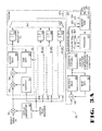
- Figure 3A provides a detailed block diagram of a parallel correlator circuit according to one embodiment of the present invention.
- the circuit of Figure 3A consists of a parallel correlator 300 and a processor/memory circuit 320.
- Parallel correlator 300 can process in parallel all possible phases of a given PN sequence corresponding to a single GPS signal.
- Parallel correlator 300 represents a single channel parallel correlator, such as channel 1 parallel correlator 300a of parallel correlator circuit 208 in Figure 2 .
- a multiplicity of such structures 300 can be constructed to process in parallel a multiplicity of GPS channels, as illustrated in Figure 2 .
- Parallel correlator 300 of figure 3A effectively implements 2046 individual correlator circuits.
- the input signal 302 is input in parallel to 64 separate multi-correlator units.
- Multi-correlator unit 301 illustrates the components within each multi-correlator unit.
- Figure 3A contains block structures for the second unit 303, the third unit 305, and the 64th unit 307. It should be understood that the structures for multi-correlator units 2-64 contain the same elements illustrated in first multi-cotrelator unit 301.
- each of the multi-correlator units performs the function of 32 parallel correlators.
- each multi-correlator unit contains a PN generator 312 that is time shared among 32 successive PN one-half chip phases, or "lags".
- PN generator 312 produces replicas of the C/A (coarse/acquisition) code for any one of the satellites in the GPS constellation.
- Each lag represents a particular time position associated with the PN frame.
- As one data sample is input to parallel correlator 300, it is multiplied by each of 32 successive half-chips from the PN generator 312 and summed with similar results for previous data samples using the loop integrator composed of adder 306 and delay line 308.
- the multi-correlator unit 301 is run at 32 times the PN sample rate (e.g., 32x2.046 MHz) and thus the unit utilizes a clock that may be considered to have 32 phases. In each phase (approximately 1/64 microsecond in length), a particular PN lag is processed. When the next data sample is input, the process repeats, except that the PN generator 312 is advanced one-half chip.
- the PN sample rate e.g., 32x2.046 MHz
- the output from 32-stage delay 308 is dumped once per PN frame or a multiple thereof.
- Each multi-correlator unit processes a separate group of 32 lags.
- the first unit 301 processes lags 0-31; the second unit 303 processes lags 32-63; the third unit 305 processes lags 64-95; and so on until the 64th unit 307 which processes lags 2016-2047.
- the 32-stage delay circuit 308 may be implemented in memory in which the output from multiplier 304 is written to successive addresses. The data is read from a particular address, added to the input signal in adder 304, and the sum is written to the same address. The address counter is then advanced, and the process repeated. In the 32-stage delay, this operation is performed 32 times.
- the output of the loop integrator within multi-correlator unit 301 is output from the 32-stage delay 308 to squaring circuit 314 to remove effects of carrier frequency error and data inversions.
- Each of the 64 multi-correlator units contains its own dedicated squaring circuit. For example, the output from the loop integrator for the second multi-correlator unit 303 is output to squaring circuit 313; the output from the loop integrator for the third multi-correlator unit 305 is output to squaring circuit 315; and the output from the loop integrator for the 64th multi-correlator unit 307 is output to squaring circuit 317. Only 32 successive outputs from the multi-correlators need to be processed by the squaring circuits at the end of each PN frame.
- the output signals from all 64 multi-correlator loops are input to a multiplexer 316 which produces a single output signal from the 64 input signals,
- the output from multiplexer 316 is transmitted to a following loop integrator which comprises a 2046-stage delay 328, dump gate 330, and adder 332.
- This loop integrator provides post-detection integration of all the constituent correlators (2046 in number). Note that since the dump rate at the output of multiplexer 316 corresponds to the PN frame rate for each of the 2046 correlators, the average data rate into the following post-detection integrator is only 2.046 Msamples/sec. Hence, the following post-detection loop integrator may be implemented with relatively inexpensive circuitry.
- the 2046-stage delay circuit 328 may be implemented in memory in which the output from multiplexer 316 is read from and written to successive addresses. The data is read from a particular address, added to the input signal in adder 332, and the sum is written to the same address. The address counter is then advanced, and the process repeated. In the 2046-stage delay, this operation is performed 2046 times.
- the output signal from delay circuit 328 of the post-detection loop integrator is input to a comparator 326.
- Comparator 326 compares the post-detection output signal against a predetermined threshold value. If the post-detection output signal exceeds the level of the threshold, an alarm signal 325a is transmitted to processor 322.
- processor 322 receives separate alarm signals 325a-325n from each of the parallel correlator circuits for channels 1-N within correlator circuit 208.
- Processor 322 provides a control output to Doppler compensation unit 334 and the PN generator 312 and dump gate circuits 310 within each of the 64 multi-correlator units 301-307. The output from the Doppler compensation circuit 334 is combined with the I/Q input signal 302 in multiplier 336.
- the threshold comparator circuit 326 also produces an acquisition signal 323 a which may be used for more precise time-of-arrival measurement.
- Acquisition signal 323a which represents the acquisition signal for channel 1 parallel correlator 300a, is input to register bank 324 within processing unit 320.
- register bank 324 also receives separate acquisition signals 323b-323n from each of the parallel correlator circuits for channels 2-N within correlator circuit 208.
- Register bank 324 stores data in the vicinity of the threshold crossing detected by threshold comparator 326. It should be noted that register bank 324 may be implemented in a memory with addressable storage locations.
- the input sample rate is a multiple of the chip rate. If the input signal contains a transmitted waveform matched to a given correlator, the data out of multiplexer 316 will contain a narrow spike corresponding to lags spanning a width of approximately one chip duration. One spike will occur for each frame period and provides time-of-arrival information, modulo one PN frame period. If squaring circuits 311-317 were deleted, then the signal, being quadrature represented, produces a spike which is a complex number. Its polarity reverses in phase at the data baud boundaries in accordance with the transmitted data stream. In addition, the phase angle may be slowly advancing or retarding in time due to small frequency differences between the received signal carrier frequency and the locally generated frequency.
- each of these spikes may be obscured by noise and hence are not directly usable for time-of-arrival measurement.
- the output of the multi-correlator units may be detected via a square-law operation, in order to remove the effect of varying phase angles.
- the energy from one PN frame is then added to that of the previous frame through a delay line integrator (e.g., 328). For a delay of one PN frame, a spike from a previous frame will be delayed by exactly one PN frame, and hence this energy will exit the delay line just as the spike from the next frame is about to enter the delay line.
- the spikes are then added together by the adder circuit 332 to produce a stronger spike.
- the random portions of noise will be incoherently added (a DC level will be increased) and hence will only grow as the square-root of the number of frames so summed.
- the DC level associated with the noise may be determined through an averaging process at the integrator output and subtracted from this final output. This eases the determination of an appropriate detection threshold in comparator 326.
- parallel correlator 300 can also be used to perform tracking of GPS signals as well as signal acquisition, thus allowing a common hardware to be used for both tracking and acquisition.
- tracking of a GPS signal only a small subset ofPN lags need to be examined at a rate of approximately once per PN frame.
- data may be extracted from the multi-correlator units and passed to a register bank at the appropriate times which correspond to the times in which the signal is in the vicinity of an initial acquisition threshold crossing.
- the microprocessor may then perform tracking and demodulation functions within its circuitry in a standard manner.
- the microprocessor feeds bock signals to the Doppler compensation circuitry, PN circuitry and dump gates in order to maintain proper tracking, during this operation.
- register bank 324 receives a tracking signal 327a from multi-correlator unit 301. Tracking signal 327a is generated from the output of 32-stage delay circuit 308 for the first multi-correlator unit. It should be noted, however, that tracking signal 327a could also be generated from the output of any of the other 64 multi-correlator units 303-307, or a multiplexed output from any combination of the multi-correlater units 301-307. According to one embodiment of the present invention, register bank 324 receives separate tracking, signals 327b-327n from each of the parallel correlator circuits for channels 2-N within correlator circuit 208.
- the parallel correlator circuit 300 may be reduced in complexity by not processing in parallel 2046 lags but only a subset of 2046 lags. In this case, parallel correlator circuit 300 would "step" through a portion of such lags at a time.
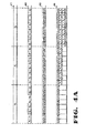
- Figure 4A provides a timing and data analysis of the operation of the multi-correlators unit 301 of Figure 3A .
- the input and Doppler compensation circuitry 336 and 334 are initially ignored.
- an 8-stage delay is used instead of a 32-stage delay for delay line 308.
- the input sample rate of input signal 302 is one sample per chip and that data is real, rather than quadrature sampled.
- delay line 308 contains all zeros.
- the period of the PN stream is n chips and this period is referred to as the "frames length".
- a standard correlator such as that illustrated in Figure 1 , multiplies the input data stream (d 0 , d 1 , d 2 ,...) by the locally generated PN sequence (p 0 , p 1 , p 2 , ...p n-1 ,p 0 , p1, p2,...) and sums the result. If the input data stream contains a signal with this PN sequence, and if it is in time alignment with the PN sequence, a large output results.
- the multiplication operation will remove the polarity inversions of the PN sequence and allow a coherent summation. If, however, the locally generated PN sequence is not time aligned with the input data stream D, another time alignment must be tried.
- the sample rate equals the chip rate.
- the signal sample rate is often two samples per chip and the delays between the locally generated PN sequence and the received data signal are adjusted in increments of one-half chip or less in order to avoid losses due to partial alignment.
- correlators either use one correlator element and sequentially try all phases of the local reference relative to the received signal, or else utilize a multiplicity of such elements in order to speed up the search time.
- a correlator must integrate over approximately 10 PN frames (10 milliseconds) in order to achieve sufficient signal energy to ensure good probability of detection.
- searching over 1023 possible lags can take up to 10 seconds.
- This process must be performed for a multiplicity of the GPS signals that are received in order to provide timing information from at least four of the satellites in view (for a three position fix),
- Figure 4A illustrates how multi-correlator unit 301 within parallel correlator 300 can compute the correlation function for a large number of lags, with a common set of hardware. In this case, the hardware requirement is much less than would be the case if separate correlators, utilizing separate hardware, were used.
- the input data stream corresponds to input signal 302 which is input to adder 306 in multi-correlator unit 301.
- data stream 401 is illustrated as consisting of windows d 0 , d 1 , and d 2 , it is understood however, that data stream 401 is typically of length 1023 for a standard C/A signal.
- the rate of data stream 401 is approximately 1.023 Msamples per second.
- the PN generator is run (for this example) at a rate of 8 times the input data rate. Hence for the first input data word, the PN generator 312 cycles through the first 8 chips of the sequence. Each time the PN generator 312 is clocked, its output is multiplied by the input data word by the multiplier 304, passed through the adder 306 and placed in the delay line 308 (for this example the delay line of length eight).
- the multiplication operation is illustrated as line 403 of Figure 4A which represents the data at the output of multiplier 304 within multi-correlator unit 301.
- a new data sample enters (e.g., d 1 in place of d 0 ) and PN generator 312 is reset, but not to the phase that was used at the start of the previous signal sample. Instead, it is set to a phase displaced by one chip from that phase.
- the successive PN chips provided by the generator 312 are p 0 , p 1 , p 2 ,...p 7 .
- the PN chips provided are p 1 , p 2 , ... p 8 , and so on.
- Line 404 of Figure 4A illustrates the sequence of data provided at the output of adder 306 and stored in delay line 308.
- Line 404 represents a standard correlation between the sequence p 0 , p 1 , p 2 ,... and the data d 1 , d 2 , d 3 , ...
- a correlation over one frame of data would be complete after n samples, where n equals the frame length.
- Examining the first output of the adder right after each sample arrives yields a first data sample of p 0 d 0 , a second data sample of p 0 d 0 +p 1 d 1 , a third data sample of p 0 d 0 +p 1 d 1 +p 2 d 2 , and so on.
- multi-correlator unit 301 would provide for 32 successive lags, rather than 8 in the above example. Furthermore, each of these lags would be one-half chip delayed relative to a prior lag, instead of one-chip delayed as in the above example. If multiple channels of multi-correlator units 301 are used, then each would be assigned a different set of lags and hence each would produce a PN sequence displaced in time from that of an adjacent channel by 32 lags.
- PN generator 312 of the first multi-correlator unit 301 produces the sequence p 0 , p 1 , ..., p 31 , p 1 , p 2 , ..., p31
- the PN generator of the second multi-correlator unit 303 would simultaneously produce the sequence p32, p33, ..., p63, p33, p34, ...., p63.
- 64 of these multi-correlator channels 301-307 will produce all the lags for an entire PN frame. This corresponds to 2046 lags for 1023 chips delayed by one-half chip per lag.
- the last two lags, provided by multi-correlator unit 307 are extraneous (actually they are the same as lags 0 and 1), since the frame length is 1023 chips or 2046 half chips.
- the correlation outputs from the delay line of each multi-correlator channel are passed through magnitude-squaring circuits (e.g., 314).
- the correlation process cannot be run indefinitely since data phase inversions in the received signal will end the coherent integration gain; in addition small Doppler errors will also end this gain.
- the correlation process is ended after each PN frame period, and the dump gate 310 is opened at this time for 32 successive PN samples, to allow correlation to begin anew.
- the data from the previous correlation period is passed through the aforementioned magnitude-squaring circuit 314 and then combined with similar outputs from other correlation channels 303, 305, etc. (if present), through multiplexer 316.
- the dump gates 310 of the various multi-correlator units (301,303,305, etc.) operate at times displaced from one another, In this case, the operation of multiplexing all the data from the various channels into one stream is simplified.
- multi-correlator unit 301 At the end of a PN frame, multi-correlator unit 301 produces 32 successive lag outputs corresponding to one entire PN frame. If the time of the dump gate opening of multi-correlator unit 303 is displaced in time by 32 clock cycles, then the data provided by multi-correlator unit 303 at the end of a PN frame will not overlap in time the data from multi-correlator unit 301. Thus, events can be timed such that 2046 samples would be burst out through multiplexer 316 at the end of each PN frame without overlapping one another in time.
- This data which has been squared in magnitude (or "detected"), then enters the delay line integrator made up of 2046-stage delay line 328 and adder 332.
- This circuit adds the detected data from one PN frame to that from the previous frames. This is due to the fact that the delay line 328 exactly equals the length of one PN frame, so that data emerging from it arrives exactly at a time coincident with one PN frame duration.
- the summation operation performed by adder 332 continue as long as desired, consistent with desired signal sensitivity and acquisition time, and is terminated by dump gate 330 being opened for one PN interval.
- Data from the delay-line integrator is compared to a detection threshold in comparator 326 to detect the presence of a signal.
- Comparator 326 generates an alarm signal 325a to processor 322 upon a threshold crossing. This alarm signal allows the measurement of time-of-arrival through the time that such an alarm is sent. The times of the alarm interrupts may be read by processor 322 using an internal counter (not shown) within the processor, or one external to it.
- the values of the data at the threshold crossing and in the vicinity of the threshold crossing may be used together with standard interpolation algorithms to refine the precise location of the correlation peak.
- the data magnitudes may be stored in register bank 324 to allow this interpolation to be performed by processor 322. This approach can permit measurement of such an arrival time to an accuracy as much as 100 times better than the time interval between data samples (which is approximately 500 nanoseconds).
- processor 322 may receive threshold crossing information from a multiplicity of channels, 1-N.
- each channel may be assigned to a PN code for a unique satellite.
- one or more channels may sequentially search through a series of PN codes.
- several channels may be assigned the same PN code but different Dopplers (through Doppler compensation circuit 334). This may be an effective acquisition strategy when the initial Doppler uncertainty is high and where certain satellites are preferable (e.g., higher in the sky).
- a tracking process may begin in which the PN epochs and carrier are continuously tracked and the satellite data message may be read by removal of the PN data. These operations may be performed by setting a group of correlators to epochs that are in the vicinity of the time of the threshold crossing of a particular satellite. During this time, the dump gate 310 is normally set to a rate that is a multiple of the data rate, e.g., 100 Hz. The correlator output is taken in pre-detected (in-phase/quadrature) form just prior to magnitude-square block 314, and stored in register bank 324 which is accessible by processor 322.
- the PN tracking loop can force the location of the correlation peak to stay in a particular time position by means of a control signal from the processor sent to the clocking mechanism of PN generator 312. This control signal causes the PN generator to advance or retard its phase in order to keep the correlation peak location fixed.
- the information in register bank 324 may be used by processor 322 to compute any error in carrier frequency using a standard phase-lock loop tracking method (e.g., a Costas loop).
- the processor 322 then feeds back correction frequencies to the Doppler compensation digital oscillator 334 to force the carrier frequency out of multiplier 336 to be zero.
- processor 322 controls dump gate 310 so that the dump times are properly aligned with the data boundaries. This may be accomplished by utilizing a data tracking loop within processor 322, and providing a feedback signal to dump gate 310, and each of the dump gates is the other multi-correlator units 303-307. Alternatively, if the dump rate, is very high (e.g., 1 kHz), then processor 322 may perform all such data tracking itself by manipulating the data stored in register bank 324, without such dump gate feedback. This latter approach, however, requires higher processor speed.
- one group of 32 multi-correlator units 301 per satellite signal being tracked is more than adequate to provide the necessary information for tracking and demodulation of satellite signals.
- the peak correlator output and those just prior to and after the peak need be utilized for these functions.
- the additional multi-correlator units of a group like 301 can be used for dropout situations to rapidly re-search for the location of a correlation peak that may have moved during this dropout period.
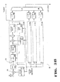
- Figure 3B provides a detailed block diagram of a parallel correlator circuit according to an alternative embodiment of the present invention.
- the alternate parallel correlator of Figure 3B uses a common portion of the PN signal which is correlated against delayed versions of the input data stream.
- the parallel correlator of Figure 3B is similar to the parallel correlator of Figure 3A with the addition of an extra delay line loop in the signal path prior to the PN generator/mixer circuit.
- Figure 4B provides a timing and data analysis of the operation of the multi-correlator unit of Figure 3B .
- the input and Doppler compensation circuitry is initially ignored.
- an 8-stage delay is used instead of a 32-stage delay for delay line 308.
- the input sample rate of input signal is one sample per chip and that data is real, rather than quadrature sampled.
- Figure 4B is similar to Figure 4A , except that the p and d terms, corresponding to the PN and data sequences respectively, are reversed.
- Multi-correlator unit 370 illustrates the components within each multi-correlator unit.
- Figure 3B contains block structures for the second unit 362, the third unit 363, and the 64th unit 364. It should be understood that the structures for multi-correlator units 2-64 contain the same elements illustrated in first multi-correlator unit 370. As illustrated for the first unit 370, each multi-correlator unit contains a PN generator 356 that is time shared among 32 successive PN one-half chip phases, or "lags".
- an I/Q input signal 373 is passed through the Doppler compensation circuitry containing compensation circuit 351 and multiplier 350, and is then loaded into register 352.
- the multi-correlator unit 370 is run at 32 times the rate at which register 352 is loaded, that is, 32 operations take place each time a new word of data is loaded into register 352.
- 8-stage delays are used instead of the 32 indicated in Figure 3B , and that the sample rate is one sample per PN chip.
- the delay line 354 contains input data d 0 ...d 7 where these data words are in time sequence (i.e., d 0 comes first, and d 7 comes last), and d 0 is at the very right of the shift register delay line 354 and d 7 is at the left.
- the data in delay line 354 is multiplied by the first PN chip from PN generator 356 using multiplier 355, and then stored in the loop accumulator containing adder 357, delay line 358, and dump gate 359.
- the first chip p 0 is multiplied by the first data word do by multiplier 355 and then placed into delay line 358
- Delay line 358 is assumed to be initially empty and dump gate 359 is placed in the closed (that is, pass through) position.
- the shift register delay lines 354 and 358 are then circularly shifted.
- Multiplexer 353 is placed in position so that the bottom path 371 is selected. This places the data word d 1 at the end of delay line 354.
- Data word d 1 is then multiplied by the same PN coefficient p 0 by multiplier 355 and placed in the delay line 358.
- the delay line contains the terms d 0 p 0 and d 1 p 0 , as shown in block 410 (corresponding to line 408 for group p 0 ).
- the next six clock periods store into delay line 358 the data d 2 p 0 , d 3 p 0 , ..., d 7 p 0 .
- the multiplexer 353 is set to receive data from the upper path 372 (data word d 8 ).
- Register 352, delay line 354, and PN Generator 356 are then clocked once, but delay line 358 is not clocked at this time. This results in delay line 354 containing data words d 1 ...d 8 , when PN generator 356 produces output p 1 .
- the PN generator 356 next produces output p 1 ,
- the data word d 0 that was previously at the output of delay line 354 is discarded and multiplexer 353 is configured to accept data from the bottom path 371 to permit a circular shifting operation.
- the next 8 high speed clock cycles perform the same computations described above in which both delay line 354 and delay line 358 are circularly shifted and the contents of delay line 358 are added to the data from delay line 354.
- the adder circuit 357 provides the accumulation function.
- the output of these operations is illustrated in the p 1 group of Figure 4B , with the results shown in block 411 (corresponding to line 408 for group p 1 ).
- register 352, delay line 354, and PN generator 356 are again clocked once with multiplexer 353 set to the upper position. Again, delay line 358 is not clocked during this period, so that at this point, delay line 354 contains data words d 2 ...d 9 , when PN generator 356 produces output p 2 .
- the PN generator 356 next produces output p 2 .
- the above mentioned eight cycle process is once again performed, and the result is shown in block 412 (corresponding to line 408 for group p 2 ). This entire process repeats until a frame of 1023 samples of data (or multiple thereof) are processed (in a typical embodiment). At this point the dump gate 359 may be placed in an open condition so that a new set of data may be accumulated by delay line 358.
- the correlation output from delay line 358 of multi correlator 370 provides a tracking signal for the I/Q input signal. This output is also input to magnitude-squaring circuit 360.
- the output front each of the other multi-correlator channels (362, 363, 364) are passed through respective magnitude-squaring circuits (e.g., 365, 366, 367).
- the data from each magnitude-squaring circuit is combined with similar outputs from the other correlation channels through multiplexer 361 to produce the acquisition signal for the I/Q input signal.
- the last eight sums 412 shows a correlation of the data sequence d 0 , d 1 , d 2 , ... against the PN sequence p 0 , p 1 , P2 , ... for eight successive lags (relative phasings between the two sequences). It will be appreciated that this result is very similar to the result illustrated in the Figure 4A timing diagram with some subtle differences. As shown in Figure 4A , the same data block is correlated against shifted versions of the PN sequence. In Figure 4B , the same PN block is correlated against different data blocks. For most situations the difference is inconsequential. However, the circuitry of Figure 3A is simpler than that of Figure 3B and hence would normally be preferred.
- multicorrelators 362, 363, ... 364 each contain the same circuitry as multicorrelator 370.
- the data input to 362 (multicorrelator #2) is fed from the output of the 32-stage delay line 354 of the previous multicorrelator 370 (multicorrelator #1), and similarly, the 32-stage delay line of multicorrelator 362 feeds the input of multicorrelator 363, and so on.
- the data in the 32-stage delay line of multi-correlator 370 is delayed from the corresponding data in the 32-stage delay line of multicorrelator 362 by 32 samples, and that data in the 32-stage delay line of multicorrelator 362 is delayed from the corresponding data of multicorrelator 363 by another 32 samples, and so on.
- the collection of all multicorrelator circuits 370, 362, 363, ... 364 are processing 2046 successive data samples with the same PN generator. Therefore, although Figure 3B indicates that one PN generator is used per multicorrelator, one PN generator for the entire set of 64 multicorrelators can be utilized.
- the output of the PN generator 356 can be sent to the mixers (corresponding to mixer 355) in each of the other multicorrelator circuits 362, 363, ... 364.
- the multicorrelator circuits 362, 363, ... 364 may have their PN generators deleted.
- the output of register 352 is input in parallel to all 64 multicorrelators, instead of each multi-correlator feeding data to the succeeding one.
- 64 different PN generators or one PN generator with 64 different outputs
- the outputs of the PN generators of succeeding multicorrelators are displaced in time (or phase) from one another by minus 32 half-chips.
- this approach combines correlator 300 of Figure 3A with the previously described correlator 380 of Figure 3B .
- each multicorrelator processes 32 different correlation lags by delaying the input signal relative to a fixed PN sequence, but different multicorrelators ensure that different groups of 32 lags are processed by delaying the PN phase relative to the previous multi-correlator by 32 lags.
- FIG. 5 illustrates the implementation of correlator circuit 300 in a conventional GPS receiver 500 according to one embodiment of the present invention.
- the GPS receiver is conventional in the sense that it receives GPS signals and determines pseudoranges and also reads the satellite data messages in the GPS signals in order to determine satellite ephemeris, and then also determines the position of the receiver from the pseudoranges and the ephemeris.
- GPS signals are received by GPS antenna 502 and input to GPS receiver 500 through input circuit 504.
- the PN codes within the received GPS signals are acquired and tracked in acquisition circuit 500a together with an external processor 510 in accordance with the operation described above with respect to Figures 2-4 .
- the output of acquisition circuit 500a comprises the pseudorange data 508 corresponding to the signals received from each GPS satellite from which a signal was receive.
- Each satellite also transmits ephemeris data 506 which is received by input circuit 504 and demodulated by tracking and demodulation circuit 500b.
- Processor 510 processes the ephemeris and pseudorange data to determine the location of the receiver 500.
- the output of processor 510 drives an input/output device such as display device 512 which graphically or textually displays the location of the receiver.
- the circuit of Figure 3A performs both the acquisition and tracking functions together with processor 510.
- FIG. 6 illustrates the implementation of acquisition circuit in a GPS receiver 600 according to an alternative embodiment of the present invention.
- GPS receiver 600 is a combined GPS and communication receiver transmitter.
- Receiver 600 contains a GPS receiver stage including acquisition circuit 300 and communication transceiver section 620.
- GPS signals are received through GPS antenna 602 and input to acquisition circuit 300 which acquires the PN codes for the various received satellites.
- the pseudorange data produced by acquisition circuit 300 are processed by processor 612 for transmittal by transceiver 620.
- Transceiver 620 contains a transmit/receive switch 608 which routes communication signals (typically RF) to and from communication antenna 604 and receiver 600.
- Received communication signals are input to communication receiver 610 and passed to processor 612 for processing.
- Communication signals to be transmitted from processor 612 are propagated to modulator 614 and frequency converter 616.
- Power amp 618 increases the gain of the signal to an appropriate level for transmission to base station 606.
- pseudorange data generated by acquisition circuit 600 is transmitted over a communication link to base station 606.
- Base station 606 determine the location of receiver 600 based on the pseudorange data from the remote receiver and ephemeris data received from its own GPS receiver or other sources of such data. The location data can then be transmitted back to GPS receiver 600 or to other remote locations.
- the communication link between receiver 600 and base station 606 may be implemented in a number of various embodiments including a direct link or cellular phone link.
- Pseudolites are ground based transmitters which broadcast a PN code (similar to a GPS signal) modulated on an L-band carrier signal, generally synchronized with GPS time. Each transmitter may be assigned a unique PN code so as to permit identification by a remote receiver. Pseudolites are useful in situations where GPS signals from an orbiting satellite might by unavailable, such as tunnels, mines, buildings or other inclosed areas.
- PN code similar to a GPS signal
- L-band carrier signal generally synchronized with GPS time.
- Each transmitter may be assigned a unique PN code so as to permit identification by a remote receiver.
- Pseudolites are useful in situations where GPS signals from an orbiting satellite might by unavailable, such as tunnels, mines, buildings or other inclosed areas.
- the term "satellite”, as used herein, is intended to include pseudolites or equivalents of pseudolites
- GPS signals as used herein, is intended to include GPS-like signals from pseudolites or equivalents of pseudolite
- GPS Global Positioning Satellite
Applications Claiming Priority (4)
| Application Number | Priority Date | Filing Date | Title |
|---|---|---|---|
| US5064797P | 1997-06-24 | 1997-06-24 | |
| PCT/US1998/007471 WO2000010030A1 (fr) | 1998-04-14 | 1998-04-14 | Recepteur gps a acquisition rapide et a grande sensibilite |
| EP98926225A EP1015908B1 (fr) | 1997-06-24 | 1998-05-29 | Systeme correlateur gps hautement parallele et procede correspondant |
| EP09003719A EP2075591A1 (fr) | 1997-06-24 | 1998-05-29 | Système et procédé de corrélateur GPS hautement parallèle |
Related Parent Applications (2)
| Application Number | Title | Priority Date | Filing Date |
|---|---|---|---|
| EP98926225.8 Division | 1998-05-29 | ||
| EP09003719.3 Division | 2009-03-16 |
Publications (2)
| Publication Number | Publication Date |
|---|---|
| EP2284560A1 true EP2284560A1 (fr) | 2011-02-16 |
| EP2284560B1 EP2284560B1 (fr) | 2013-06-26 |
Family
ID=22266838
Family Applications (6)
| Application Number | Title | Priority Date | Filing Date |
|---|---|---|---|
| EP98939056A Expired - Lifetime EP1071966B1 (fr) | 1997-06-24 | 1998-04-14 | Filtre adapté |
| EP10009790A Withdrawn EP2293105A3 (fr) | 1998-04-14 | 1998-04-14 | Récepteur GPS haute sensibilité à acquisition rapide |
| EP10009791A Withdrawn EP2293106A3 (fr) | 1998-04-14 | 1998-04-14 | Récepteur GPS haute sensibilité à acquisition rapide |
| EP09003719A Ceased EP2075591A1 (fr) | 1997-06-24 | 1998-05-29 | Système et procédé de corrélateur GPS hautement parallèle |
| EP10183503.1A Expired - Lifetime EP2284560B1 (fr) | 1997-06-24 | 1998-05-29 | Système et procédé de corrélateur GPS hautement parallèle |
| EP98926225A Expired - Lifetime EP1015908B1 (fr) | 1997-06-24 | 1998-05-29 | Systeme correlateur gps hautement parallele et procede correspondant |
Family Applications Before (4)
| Application Number | Title | Priority Date | Filing Date |
|---|---|---|---|
| EP98939056A Expired - Lifetime EP1071966B1 (fr) | 1997-06-24 | 1998-04-14 | Filtre adapté |
| EP10009790A Withdrawn EP2293105A3 (fr) | 1998-04-14 | 1998-04-14 | Récepteur GPS haute sensibilité à acquisition rapide |
| EP10009791A Withdrawn EP2293106A3 (fr) | 1998-04-14 | 1998-04-14 | Récepteur GPS haute sensibilité à acquisition rapide |
| EP09003719A Ceased EP2075591A1 (fr) | 1997-06-24 | 1998-05-29 | Système et procédé de corrélateur GPS hautement parallèle |
Family Applications After (1)
| Application Number | Title | Priority Date | Filing Date |
|---|---|---|---|
| EP98926225A Expired - Lifetime EP1015908B1 (fr) | 1997-06-24 | 1998-05-29 | Systeme correlateur gps hautement parallele et procede correspondant |
Country Status (13)
| Country | Link |
|---|---|
| US (1) | US6289041B1 (fr) |
| EP (6) | EP1071966B1 (fr) |
| JP (1) | JP4422337B2 (fr) |
| KR (1) | KR100576959B1 (fr) |
| CN (1) | CN1331311C (fr) |
| AU (1) | AU7811298A (fr) |
| BR (1) | BR9815813B1 (fr) |
| CA (1) | CA2328310C (fr) |
| FI (1) | FI110821B (fr) |
| HK (1) | HK1035932A1 (fr) |
| IL (1) | IL138982A0 (fr) |
| MX (1) | MXPA00010078A (fr) |
| WO (2) | WO2000010030A1 (fr) |
Families Citing this family (147)
| Publication number | Priority date | Publication date | Assignee | Title |
|---|---|---|---|---|
| BR9804923A (pt) * | 1997-05-19 | 2001-09-18 | Integrated Data Communications | Sistema e processo para comunicação de dados de geo posicionamento em três eixos geométricos, por tempo auferido, dentro de redes de telecomunicação |
| US6771629B1 (en) | 1999-01-15 | 2004-08-03 | Airbiquity Inc. | In-band signaling for synchronization in a voice communications network |
| US6690681B1 (en) | 1997-05-19 | 2004-02-10 | Airbiquity Inc. | In-band signaling for data communications over digital wireless telecommunications network |
| US6493338B1 (en) | 1997-05-19 | 2002-12-10 | Airbiquity Inc. | Multichannel in-band signaling for data communications over digital wireless telecommunications networks |
| US6816710B2 (en) * | 1998-05-06 | 2004-11-09 | Snaptrack, Inc. | Method and apparatus for signal processing in a satellite positioning system |
| US6657986B1 (en) * | 1998-07-10 | 2003-12-02 | Hyundai Electronics America | Variable clock rate correlation circuit and method of operation |
| US7711038B1 (en) | 1998-09-01 | 2010-05-04 | Sirf Technology, Inc. | System and method for despreading in a spread spectrum matched filter |
| US7545854B1 (en) * | 1998-09-01 | 2009-06-09 | Sirf Technology, Inc. | Doppler corrected spread spectrum matched filter |
| US6297770B1 (en) * | 2000-05-23 | 2001-10-02 | Mitsubishi Denki Kabushiki Kaisha | Global positioning system and global positioning method with improved sensitivity by detecting navigation data inversion boundaries |
| US6618431B1 (en) * | 1998-12-31 | 2003-09-09 | Texas Instruments Incorporated | Processor-based method for the acquisition and despreading of spread-spectrum/CDMA signals |
| US7130332B1 (en) * | 1999-04-20 | 2006-10-31 | Symmetricom, Inc. | Pilot tracking for synchronization using correlation between digital signal and locally generated version of PN signal |
| US9020756B2 (en) * | 1999-04-23 | 2015-04-28 | Global Locate, Inc. | Method and apparatus for processing satellite positioning system signals |
| US6606346B2 (en) * | 2001-05-18 | 2003-08-12 | Global Locate, Inc. | Method and apparatus for computing signal correlation |
| US6829534B2 (en) | 1999-04-23 | 2004-12-07 | Global Locate, Inc. | Method and apparatus for performing timing synchronization |
| US6704348B2 (en) | 2001-05-18 | 2004-03-09 | Global Locate, Inc. | Method and apparatus for computing signal correlation at multiple resolutions |
| US6453237B1 (en) | 1999-04-23 | 2002-09-17 | Global Locate, Inc. | Method and apparatus for locating and providing services to mobile devices |
| US6847676B1 (en) * | 1999-06-30 | 2005-01-25 | University Of Hong Kong | All-lag spread-spectrum correlators with rotating references |
| US6868115B1 (en) * | 1999-06-30 | 2005-03-15 | University Of Hong Kong | All-lag spread-spectrum correlator |
| DE19933542A1 (de) * | 1999-07-16 | 2001-01-25 | Siemens Ag | Verfahren und Vorrichtung zur Synchronisation von Mobilfunkempfängern in einem Mobilfunksystem |
| US6594328B1 (en) * | 1999-07-28 | 2003-07-15 | Motorola, Inc. | Method and apparatus for facilitating an estimation of a carrier frequency error in a receiver of a wireless communication system |
| KR20010035967A (ko) * | 1999-10-05 | 2001-05-07 | 서평원 | 코드분할다중접속 시스템의 다중 사용자 신호 동기 획득 장치 및 그 방법 |
| FI111578B (fi) * | 1999-10-13 | 2003-08-15 | U Nav Microelectronics Corp | Korrelaattori |
| US6421372B1 (en) * | 1999-11-10 | 2002-07-16 | Itt Manufacturing Enterprises, Inc. | Sequential-acquisition, multi-band, multi-channel, matched filter |
| US6985542B1 (en) * | 2000-06-02 | 2006-01-10 | Cellguide Ltd. | Coherent processing of satellite signals to locate a mobile unit |
| US6370182B2 (en) * | 2000-02-10 | 2002-04-09 | Itt Manufacturing Enterprises, Inc. | Integrated beamforming/rake/mud CDMA receiver architecture |
| FI20000819A (fi) * | 2000-04-06 | 2002-01-25 | Nokia Mobile Phones Ltd | Menetelmä vastaanottimessa ja vastaanotin |
| US6810072B1 (en) * | 2000-05-30 | 2004-10-26 | Nokia Corporation | System for acquiring spread spectrum signals |
| US6778136B2 (en) | 2001-12-13 | 2004-08-17 | Sirf Technology, Inc. | Fast acquisition of GPS signal |
| US7970411B2 (en) | 2000-05-18 | 2011-06-28 | Sirf Technology, Inc. | Aided location communication system |
| US8078189B2 (en) * | 2000-08-14 | 2011-12-13 | Sirf Technology, Inc. | System and method for providing location based services over a network |
| US8116976B2 (en) | 2000-05-18 | 2012-02-14 | Csr Technology Inc. | Satellite based positioning method and system for coarse location positioning |
| US7970412B2 (en) * | 2000-05-18 | 2011-06-28 | Sirf Technology, Inc. | Aided location communication system |
| US7929928B2 (en) | 2000-05-18 | 2011-04-19 | Sirf Technology Inc. | Frequency phase correction system |
| US6389291B1 (en) * | 2000-08-14 | 2002-05-14 | Sirf Technology | Multi-mode global positioning system for use with wireless networks |
| US7813875B2 (en) * | 2002-10-10 | 2010-10-12 | Sirf Technology, Inc. | Layered host based satellite positioning solutions |
| US7546395B2 (en) * | 2002-10-10 | 2009-06-09 | Sirf Technology, Inc. | Navagation processing between a tracker hardware device and a computer host based on a satellite positioning solution system |
| US6738713B2 (en) | 2000-05-26 | 2004-05-18 | Parthus (Uk) Limited | Positioning apparatus and method |
| JP2004506219A (ja) | 2000-08-09 | 2004-02-26 | スカイビッツ,インコーポレイテッド | Gps受信機におけるコード位相ならびにキャリア周波数の高速捕捉システム並びに方法 |
| US6961019B1 (en) * | 2000-08-10 | 2005-11-01 | Sirf Technology, Inc. | Method and apparatus for reducing GPS receiver jamming during transmission in a wireless receiver |
| US7106786B2 (en) | 2000-08-24 | 2006-09-12 | Sirf Technology, Inc. | Method for reducing auto-correlation or cross-correlation in weak signals |
| US7545850B1 (en) * | 2000-08-24 | 2009-06-09 | Sirf Technology, Inc. | Analog compression of GPS C/A signal to audio bandwidth |
| FR2813474B1 (fr) * | 2000-08-28 | 2002-12-13 | Commissariat Energie Atomique | Procede de reception non coherente dp-mok avec combinaison de trajets multiples et recepteur correspondant |
| US6665612B1 (en) * | 2000-08-29 | 2003-12-16 | Sirf Technology, Inc. | Navigation processing for a satellite positioning system receiver |
| EP1325561A4 (fr) * | 2000-09-18 | 2004-07-28 | Skybitz Inc | Systeme et procede d'acquisition rapide de phase code et de frequence porteuse dans un recepteur gps |
| US7463893B1 (en) | 2000-09-22 | 2008-12-09 | Sirf Technology, Inc. | Method and apparatus for implementing a GPS receiver on a single integrated circuit |
| GB0026982D0 (en) * | 2000-11-04 | 2000-12-20 | Koninkl Philips Electronics Nv | Spread spectrum receiver and related method |
| US6724807B1 (en) * | 2000-12-04 | 2004-04-20 | Snaptrack Inc. | Methods and apparatuses for processing of global positioning system signals with a matched filter |
| GB0029876D0 (en) * | 2000-12-07 | 2001-01-24 | Parthus Uk Ltd | Positioning apparatus and method |
| US7671489B1 (en) | 2001-01-26 | 2010-03-02 | Sirf Technology, Inc. | Method and apparatus for selectively maintaining circuit power when higher voltages are present |
| CN1325927C (zh) * | 2001-02-06 | 2007-07-11 | 皇家菲利浦电子有限公司 | 解扩gps信号的方法 |
| US6703971B2 (en) * | 2001-02-21 | 2004-03-09 | Sirf Technologies, Inc. | Mode determination for mobile GPS terminals |
| JP3633497B2 (ja) * | 2001-03-22 | 2005-03-30 | 三菱電機株式会社 | 周波数誤差推定を行う受信機および周波数誤差の推定方法 |
| TW567336B (en) | 2001-05-04 | 2003-12-21 | Asulab Sa | Radio-frequency signal receiver with means for improving the reception dynamic of said signals |
| ATE274193T1 (de) * | 2001-05-04 | 2004-09-15 | Asulab Sa | Funksignalempfänger mit mittel zur vergrösserung der dynamik des empfangs der signale |
| US6891880B2 (en) * | 2001-05-18 | 2005-05-10 | Global Locate, Inc. | Method and apparatus for performing signal correlation |
| US7769076B2 (en) | 2001-05-18 | 2010-08-03 | Broadcom Corporation | Method and apparatus for performing frequency synchronization |
| US6819707B2 (en) | 2001-05-18 | 2004-11-16 | Global Locate, Inc. | Method and apparatus for performing signal correlation using historical correlation data |
| US7567636B2 (en) * | 2001-05-18 | 2009-07-28 | Global Locate, Inc. | Method and apparatus for performing signal correlation using historical correlation data |
| US8098716B2 (en) * | 2001-05-18 | 2012-01-17 | Broadcom Corporation | Method and apparatus for providing an energy-based signal tracking loop |
| US7006556B2 (en) * | 2001-05-18 | 2006-02-28 | Global Locate, Inc. | Method and apparatus for performing signal correlation at multiple resolutions to mitigate multipath interference |
| US7190712B2 (en) * | 2001-05-18 | 2007-03-13 | Global Locate, Inc | Method and apparatus for performing signal correlation |
| US7995682B2 (en) * | 2001-05-18 | 2011-08-09 | Broadcom Corporation | Method and apparatus for performing signal processing using historical correlation data |
| US8244271B2 (en) * | 2001-05-21 | 2012-08-14 | Csr Technology Inc. | Distributed data collection of satellite data |
| US6628234B2 (en) * | 2001-07-18 | 2003-09-30 | Fast Location.Net, Llc | Method and system for processing positioning signals in a stand-alone mode |
| JP4617618B2 (ja) * | 2001-07-26 | 2011-01-26 | ソニー株式会社 | スペクトラム拡散信号の拡散符号同期検出方法および装置 |
| US6775319B2 (en) | 2001-08-16 | 2004-08-10 | Motorola, Inc. | Spread spectrum receiver architectures and methods therefor |
| US6785543B2 (en) | 2001-09-14 | 2004-08-31 | Mobile Satellite Ventures, Lp | Filters for combined radiotelephone/GPS terminals |
| US7042926B2 (en) * | 2001-11-21 | 2006-05-09 | Intel Corporation | Low complexity multiuser detector |
| US7120191B2 (en) * | 2001-12-12 | 2006-10-10 | Nokia Corporation | Method and apparatus for acquiring a ranging signal of a positioning system |
| US7649860B2 (en) * | 2002-01-31 | 2010-01-19 | Qualcomm Incorporated | Buffer-based GPS and CDMA pilot searcher |
| US6559795B1 (en) * | 2002-02-19 | 2003-05-06 | Seiko Epson Corporation | High-sensitivity infrequent use of servers |
| US6957056B2 (en) * | 2002-03-28 | 2005-10-18 | Motorola, Inc. | Receiver and method for determining an intermediate frequency in a wireless communication device |
| US7596190B2 (en) * | 2002-04-01 | 2009-09-29 | Qualcomm Incorporated | System, method, and apparatus for correction of code doppler shift |
| US6725157B1 (en) * | 2002-06-10 | 2004-04-20 | Trimble Navigation Limited | Indoor GPS clock |
| US7545319B2 (en) * | 2002-06-20 | 2009-06-09 | Sirf Technology, Inc. | Configurable satellite positioning system receivers with programmable inputs |
| US6738013B2 (en) * | 2002-06-20 | 2004-05-18 | Sirf Technology, Inc. | Generic satellite positioning system receivers with selective inputs and outputs |
| DE60220046T2 (de) * | 2002-08-02 | 2008-01-10 | Stmicroelectronics Ltd., Almondsbury | Integrierter Schaltkreis zur GPS Kodeerfassung |
| EP1387498A1 (fr) * | 2002-08-02 | 2004-02-04 | STMicroelectronics Limited | Circuit intégré pour l'acquisition de code |
| DE60238833D1 (de) * | 2002-08-02 | 2011-02-17 | St Microelectronics Srl | Integrierte Schaltung für Kodeerfassung |
| CN100409029C (zh) | 2002-08-15 | 2008-08-06 | SiRF技术公司 | 用于全球定位系统的接口 |
| EP1579234A1 (fr) * | 2002-12-16 | 2005-09-28 | Koninklijke Philips Electronics N.V. | Affichage d'informations specifiques a un emplacement pour dispositifs gps |
| US7822105B2 (en) | 2003-09-02 | 2010-10-26 | Sirf Technology, Inc. | Cross-correlation removal of carrier wave jamming signals |
| US8013787B2 (en) | 2003-09-02 | 2011-09-06 | Sirf Technology Inc. | Control and features for satellite positioning system receivers |
| US7472048B2 (en) * | 2004-02-02 | 2008-12-30 | Trimble Navigation Limited | Direct digital drive audio system and method |
| DE102004025109B4 (de) * | 2004-05-21 | 2007-05-03 | Infineon Technologies Ag | Vorrichtung und Verfahren zur Präambeldetektion und Rahmensynchronisation bei der Datenpaketübertragung |
| US7548199B2 (en) | 2004-09-20 | 2009-06-16 | The United States Of America As Represented By The Administrator Of The National Aeronautics And Space Administration | Radiation-hardened fast acquisition/weak signal tracking system and method |
| GB0421930D0 (en) * | 2004-10-01 | 2004-11-03 | Nokia Corp | Signal receiver |
| US8013789B2 (en) * | 2004-10-06 | 2011-09-06 | Ohio University | Systems and methods for acquisition and tracking of low CNR GPS signals |
| US7508810B2 (en) | 2005-01-31 | 2009-03-24 | Airbiquity Inc. | Voice channel control of wireless packet data communications |
| JP4467446B2 (ja) * | 2005-02-10 | 2010-05-26 | Necエレクトロニクス株式会社 | 高周波ic及びgps受信機 |
| US7764227B2 (en) | 2005-02-18 | 2010-07-27 | Mitsubishi Electric Corporation | Positioning apparatus |
| US20100135363A1 (en) * | 2005-03-01 | 2010-06-03 | Zhengdi Qin | Supporting a Signal Acquisition |
| US7961717B2 (en) * | 2005-05-12 | 2011-06-14 | Iposi, Inc. | System and methods for IP and VoIP device location determination |
| JP4631533B2 (ja) * | 2005-05-13 | 2011-02-16 | ソニー株式会社 | 無線通信装置 |
| JP4274166B2 (ja) * | 2005-10-06 | 2009-06-03 | セイコーエプソン株式会社 | 測位装置、測位方法及びプログラム |
| DE602006010810D1 (de) * | 2006-03-22 | 2010-01-14 | Qualcomm Inc | Breitband Frequenzdiskriminator und Funkortungsempfänger |
| US7917362B2 (en) * | 2006-04-19 | 2011-03-29 | Mediatek Inc. | Method and apparatus for determining a bit boundary of a repetition-coded signal |
| US8270529B2 (en) * | 2006-06-22 | 2012-09-18 | Nordnav Technologies Ab | Software-based spread spectrum signal processing |
| WO2008005904A2 (fr) * | 2006-06-30 | 2008-01-10 | Sirf Technology, Inc. | Architecture pour un radiorepérage hybride avec mise en œuvre de plusieurs technologies pour un affinement de position |
| US8121238B2 (en) * | 2006-06-30 | 2012-02-21 | Csr Technology Inc. | System and method for synchronizing digital bits in a data stream |
| US7711037B2 (en) * | 2006-12-22 | 2010-05-04 | Mediatek Inc. | Fractional chip correlation device and method for operating fractional chip correlation in spread spectrum receiver |
| US7773034B2 (en) * | 2006-12-27 | 2010-08-10 | Intel Corporation | Method for acquisition of GPS signals and GPS receiver with sample time error and frequency offset compensation |
| US20080159376A1 (en) * | 2006-12-31 | 2008-07-03 | Texas Instruments Incorporated | Receiver with Decision-Feedback Fading Canceller |
| US7466209B2 (en) * | 2007-01-05 | 2008-12-16 | Sirf Technology, Inc. | System and method for providing temperature correction in a crystal oscillator |
| WO2008092008A2 (fr) * | 2007-01-24 | 2008-07-31 | Ohio University | Procédé et appareil permettant l'utilisation d'un signal à trajets multiples dans une architecture gps |
| US7724612B2 (en) * | 2007-04-20 | 2010-05-25 | Sirf Technology, Inc. | System and method for providing aiding information to a satellite positioning system receiver over short-range wireless connections |
| ATE514098T1 (de) * | 2007-05-10 | 2011-07-15 | Qualcomm Inc | Gnss-signalprozessor |
| US8270457B2 (en) | 2007-06-27 | 2012-09-18 | Qualcomm Atheros, Inc. | High sensitivity GPS receiver |
| US7995683B2 (en) * | 2007-10-24 | 2011-08-09 | Sirf Technology Inc. | Noise floor independent delay-locked loop discriminator |
| CN101424736B (zh) * | 2007-10-31 | 2011-11-23 | 中国科学院微电子研究所 | 全球定位系统中的接收机快速启动和定位的方法 |
| CN101424731B (zh) * | 2007-10-31 | 2011-11-23 | 中国科学院微电子研究所 | 全球定位系统接收机信号缺失情况下快速重捕和定位的方法 |
| US7642957B2 (en) * | 2007-11-27 | 2010-01-05 | Sirf Technology, Inc. | GPS system utilizing multiple antennas |
| US8269686B2 (en) | 2007-11-27 | 2012-09-18 | Uti Limited Partnership | Dual circularly polarized antenna |
| US8705591B2 (en) * | 2007-12-05 | 2014-04-22 | Qualcomm Incorporated | Global navigation receiver |
| US8144053B2 (en) * | 2008-02-04 | 2012-03-27 | Csr Technology Inc. | System and method for verifying consistent measurements in performing GPS positioning |
| US8699984B2 (en) | 2008-02-25 | 2014-04-15 | Csr Technology Inc. | Adaptive noise figure control in a radio receiver |
| US7616064B2 (en) * | 2008-02-28 | 2009-11-10 | Noshir Dubash | Digital synthesizer for low power location receivers |
| US8478305B2 (en) * | 2008-04-09 | 2013-07-02 | Csr Technology Inc. | System and method for integrating location information into an internet phone system |
| CN101308204B (zh) * | 2008-05-30 | 2011-05-04 | 北京航空航天大学 | 多系统卫星导航相关器 |
| US8072376B2 (en) * | 2008-06-27 | 2011-12-06 | Sirf Technology Inc. | Method and apparatus for mitigating the effects of cross correlation in a GPS receiver |
| US8073414B2 (en) | 2008-06-27 | 2011-12-06 | Sirf Technology Inc. | Auto-tuning system for an on-chip RF filter |
| DE112009002036B4 (de) * | 2008-08-19 | 2022-05-19 | Trimble Navigation Limited | Verfahren und Geräte zur GNSS-Signalverarbeitung mit Ambiguitätsauswahl |
| US8040276B2 (en) * | 2008-11-24 | 2011-10-18 | National Instruments Corporation | Generation of multi-satellite GPS signals in software |
| US7994977B2 (en) * | 2008-12-02 | 2011-08-09 | Sirf Technology Inc. | Method and apparatus for a GPS receiver capable or reception of GPS signals and binary offset carrier signals |
| US20100166047A1 (en) * | 2008-12-29 | 2010-07-01 | Electronics And Telecommunications Research Institute | Method for detecting satellite navigation received signal and apparatus thereof |
| US8433283B2 (en) | 2009-01-27 | 2013-04-30 | Ymax Communications Corp. | Computer-related devices and techniques for facilitating an emergency call via a cellular or data network using remote communication device identifying information |
| JP5118088B2 (ja) * | 2009-03-09 | 2013-01-16 | スナップトラック・インコーポレーテッド | グローバルポジショニングシステム信号を獲得及び追跡する方法及び装置 |
| KR101168287B1 (ko) | 2009-03-20 | 2012-07-30 | 주식회사 코아로직 | Ttff 향상을 위한 마이크로프로세서, 그 마이크로프로세서를 포함한 gps 수신기 및 gps 위치 추적 방법 |
| US8036600B2 (en) | 2009-04-27 | 2011-10-11 | Airbiquity, Inc. | Using a bluetooth capable mobile phone to access a remote network |
| US8418039B2 (en) | 2009-08-03 | 2013-04-09 | Airbiquity Inc. | Efficient error correction scheme for data transmission in a wireless in-band signaling system |
| US8249865B2 (en) | 2009-11-23 | 2012-08-21 | Airbiquity Inc. | Adaptive data transmission for a digital in-band modem operating over a voice channel |
| JP4911220B2 (ja) * | 2009-11-30 | 2012-04-04 | セイコーエプソン株式会社 | 衛星信号捕捉方法及び衛星信号受信装置 |
| JP5716373B2 (ja) * | 2010-03-23 | 2015-05-13 | セイコーエプソン株式会社 | 相関演算方法、衛星信号捕捉方法、相関演算回路及び電子機器 |
| WO2011141821A2 (fr) | 2010-05-13 | 2011-11-17 | Uti Limited Partnership | Antenne double circulairement polarisée |
| JP5587121B2 (ja) * | 2010-09-30 | 2014-09-10 | スナップトラック・インコーポレーテッド | 整合フィルタ回路及び整合フィルタリングを実行するための方法 |
| JP2011047947A (ja) * | 2010-09-30 | 2011-03-10 | Snaptrack Inc | 高速・高感度gps受信器 |
| CN102592153A (zh) * | 2011-01-07 | 2012-07-18 | 北京中科国技信息系统有限公司 | 一种抑制系统噪声的rfid反向信号接收方法 |
| CN102098074B (zh) * | 2011-02-15 | 2014-04-09 | 北京理工大学 | 一种用于直接序列扩频系统的高动态弱信号快速捕获方法 |
| US8842717B2 (en) | 2011-03-31 | 2014-09-23 | General Dynamics Advanced Information Systems, Inc. | Method and apparatus for rapid acquisitions of GPS signals in space applications |
| CN102346256A (zh) * | 2011-08-10 | 2012-02-08 | 无锡德思普科技有限公司 | 全球导航卫星系统信号的快速捕获系统 |
| US8848825B2 (en) | 2011-09-22 | 2014-09-30 | Airbiquity Inc. | Echo cancellation in wireless inband signaling modem |
| US9077327B2 (en) * | 2013-11-04 | 2015-07-07 | Texas Instruments Incorporated | Optimized peak detector for the AGC loop in a digital radio receiver |
| CN106788585B (zh) * | 2016-12-20 | 2019-03-12 | 哈尔滨工业大学 | 基于多匹配滤波器的跳码直扩同步捕获方法 |
| CN109917429B (zh) * | 2019-03-07 | 2023-09-12 | 西安开阳微电子有限公司 | 一种b1c弱信号的捕获方法、装置及计算机存储介质 |
| TWI730378B (zh) | 2019-08-15 | 2021-06-11 | 瑞昱半導體股份有限公司 | 偵測電路以及運作方法 |
| US11743459B2 (en) * | 2020-09-29 | 2023-08-29 | Qualcomm Incorporated | Filtering process for video coding |
| CN112649820B (zh) * | 2020-11-04 | 2022-09-16 | 深圳市三七智联科技有限公司 | 射频前端芯片的信号接收方法、卫星定位系统及存储介质 |
Citations (4)
| Publication number | Priority date | Publication date | Assignee | Title |
|---|---|---|---|---|
| US4426712A (en) | 1981-05-22 | 1984-01-17 | Massachusetts Institute Of Technology | Correlation system for global position receiver |
| US4785463A (en) * | 1985-09-03 | 1988-11-15 | Motorola, Inc. | Digital global positioning system receiver |
| EP0668663A1 (fr) * | 1993-09-06 | 1995-08-23 | Ntt Mobile Communications Network Inc. | Detecteur de correlation de type progressif |
| WO1997014049A2 (fr) * | 1995-10-09 | 1997-04-17 | Snaptrack, Inc. | Recepteur gps et procede de traitement des signaux gps |
Family Cites Families (35)
| Publication number | Priority date | Publication date | Assignee | Title |
|---|---|---|---|---|
| US4112372A (en) | 1977-01-11 | 1978-09-05 | Texas Instruments Incorporated | Spread spectrum communication system |
| GB2016760B (en) | 1978-02-02 | 1982-02-24 | Plessey Co Ltd | Correlators |
| US4660164A (en) | 1983-12-05 | 1987-04-21 | The United States Of America As Represented By The Secretary Of The Navy | Multiplexed digital correlator |
| US4841544A (en) | 1987-05-14 | 1989-06-20 | The Charles Stark Draper Laboratory, Inc. | Digital direct sequence spread spectrum receiver |
| US4998111A (en) | 1989-11-27 | 1991-03-05 | Motorola, Inc. | CPS transform correlation receiver and method |
| US5101416A (en) | 1990-11-28 | 1992-03-31 | Novatel Comunications Ltd. | Multi-channel digital receiver for global positioning system |
| US5390207A (en) | 1990-11-28 | 1995-02-14 | Novatel Communications Ltd. | Pseudorandom noise ranging receiver which compensates for multipath distortion by dynamically adjusting the time delay spacing between early and late correlators |
| US5199050A (en) | 1991-04-05 | 1993-03-30 | Trw Inc. | Pseudorandom (PN) signal synchronization circuit and related method |
| DE4114058C2 (de) | 1991-04-30 | 2003-11-27 | Sel Alcatel Ag | Mehrkanalempfänger für bandgespreizte Signale |
| US5175557A (en) | 1991-07-18 | 1992-12-29 | Motorola, Inc. | Two channel global positioning system receiver |
| US5233626A (en) | 1992-05-11 | 1993-08-03 | Space Systems/Loral Inc. | Repeater diversity spread spectrum communication system |
| US5579338A (en) | 1992-06-29 | 1996-11-26 | Mitsubishi Denki Kabushiki Kaisha | Spread spectrum receiver using partial correlations |
| JPH0659013A (ja) | 1992-08-05 | 1994-03-04 | Pioneer Electron Corp | Gps受信機の信号捕捉方法 |
| US5237587A (en) | 1992-11-20 | 1993-08-17 | Magnavox Electronic Systems Company | Pseudo-noise modem and related digital correlation method |
| US5548583A (en) | 1992-11-24 | 1996-08-20 | Stanford Telecommuncations, Inc. | Wireless telephone user location capability for enhanced 911 application |
| JP2605648Y2 (ja) * | 1993-04-21 | 2000-07-31 | 日東工器株式会社 | 過充填防止弁装置 |
| US5414728A (en) | 1993-11-01 | 1995-05-09 | Qualcomm Incorporated | Method and apparatus for bifurcating signal transmission over in-phase and quadrature phase spread spectrum communication channels |
| US5572216A (en) * | 1993-11-19 | 1996-11-05 | Stanford Telecommunications, Inc. | System for increasing the utility of satellite communication systems |
| US5557641A (en) * | 1994-03-04 | 1996-09-17 | Stanford Telecommunications, Inc. | Charge-coupled-device based transmitters and receivers |
| US5576715A (en) | 1994-03-07 | 1996-11-19 | Leica, Inc. | Method and apparatus for digital processing in a global positioning system receiver |
| FR2728415B1 (fr) | 1994-12-19 | 1997-01-24 | Commissariat Energie Atomique | Procede de transmission a modulation et demodulation differentielle de phase a etalement de spectre utilisant des sequences pseudoaleatoires orthogonales |
| JP2605648B2 (ja) | 1994-12-22 | 1997-04-30 | 日本電気株式会社 | Ss受信機における逆拡散符号位相検出装置 |
| US5579014A (en) | 1995-01-20 | 1996-11-26 | General Electric Company | Parallel correlator for global positioning system receiver |
| US5663983A (en) | 1995-03-07 | 1997-09-02 | Industrial Technology Research Institute | Differentially matched filter for a spread spectrum system |
| US5589833A (en) | 1995-04-21 | 1996-12-31 | University Corporation For Atmospheric Research | Radar acquisition system |
| US5640416A (en) | 1995-06-07 | 1997-06-17 | Comsat Corporation | Digital downconverter/despreader for direct sequence spread spectrum communications system |
| US5600328A (en) | 1995-06-21 | 1997-02-04 | Matsushita Electric Industrial Co., Ltd. | Demodulator circuit in global positioning system receiver |
| ZA965340B (en) * | 1995-06-30 | 1997-01-27 | Interdigital Tech Corp | Code division multiple access (cdma) communication system |
| US5991308A (en) * | 1995-08-25 | 1999-11-23 | Terayon Communication Systems, Inc. | Lower overhead method for data transmission using ATM and SCDMA over hybrid fiber coax cable plant |
| US5736961A (en) | 1995-10-06 | 1998-04-07 | Novatel, Inc. | Dual Frequency global positioning system |
| EP0855041B1 (fr) | 1995-10-09 | 2002-12-18 | Snaptrack, Inc. | Recepteur de gps et procede de traitement de signaux de gps |
| JP2944492B2 (ja) | 1995-11-10 | 1999-09-06 | 国際電気株式会社 | マッチドフィルタ装置 |
| KR100459834B1 (ko) | 1996-04-25 | 2005-01-31 | 서프 테크놀러지, 인코포레이티드 | 멀티-비트상관기를구비한확산스펙트럼수신기 |
| US5896304A (en) | 1996-07-12 | 1999-04-20 | General Electric Company | Low power parallel correlator for measuring correlation between digital signal segments |
| US5955986A (en) * | 1997-11-20 | 1999-09-21 | Eagle Eye Technologies, Inc. | Low-power satellite-based geopositioning system |
-
1998
- 1998-02-11 US US09/021,854 patent/US6289041B1/en not_active Expired - Lifetime
- 1998-04-14 BR BRPI9815813-9A patent/BR9815813B1/pt not_active IP Right Cessation
- 1998-04-14 EP EP98939056A patent/EP1071966B1/fr not_active Expired - Lifetime
- 1998-04-14 MX MXPA00010078A patent/MXPA00010078A/es active IP Right Grant
- 1998-04-14 EP EP10009790A patent/EP2293105A3/fr not_active Withdrawn
- 1998-04-14 CA CA002328310A patent/CA2328310C/fr not_active Expired - Lifetime
- 1998-04-14 JP JP2000565416A patent/JP4422337B2/ja not_active Expired - Lifetime
- 1998-04-14 KR KR1020007011429A patent/KR100576959B1/ko not_active IP Right Cessation
- 1998-04-14 EP EP10009791A patent/EP2293106A3/fr not_active Withdrawn
- 1998-04-14 WO PCT/US1998/007471 patent/WO2000010030A1/fr active IP Right Grant
- 1998-05-29 EP EP09003719A patent/EP2075591A1/fr not_active Ceased
- 1998-05-29 WO PCT/US1998/011375 patent/WO1998059257A1/fr active Application Filing
- 1998-05-29 AU AU78112/98A patent/AU7811298A/en not_active Abandoned
- 1998-05-29 EP EP10183503.1A patent/EP2284560B1/fr not_active Expired - Lifetime
- 1998-05-29 EP EP98926225A patent/EP1015908B1/fr not_active Expired - Lifetime
- 1998-08-14 IL IL13898298A patent/IL138982A0/xx not_active IP Right Cessation
- 1998-08-14 CN CNB988140756A patent/CN1331311C/zh not_active Expired - Lifetime
-
2000
- 2000-10-13 FI FI20002274A patent/FI110821B/fi not_active IP Right Cessation
-
2001
- 2001-09-18 HK HK01106587A patent/HK1035932A1/xx not_active IP Right Cessation
Patent Citations (4)
| Publication number | Priority date | Publication date | Assignee | Title |
|---|---|---|---|---|
| US4426712A (en) | 1981-05-22 | 1984-01-17 | Massachusetts Institute Of Technology | Correlation system for global position receiver |
| US4785463A (en) * | 1985-09-03 | 1988-11-15 | Motorola, Inc. | Digital global positioning system receiver |
| EP0668663A1 (fr) * | 1993-09-06 | 1995-08-23 | Ntt Mobile Communications Network Inc. | Detecteur de correlation de type progressif |
| WO1997014049A2 (fr) * | 1995-10-09 | 1997-04-17 | Snaptrack, Inc. | Recepteur gps et procede de traitement des signaux gps |
Non-Patent Citations (1)
| Title |
|---|
| ROBERT VAN WECHEL: "Fast Acquisition Correlators for GPS", PROC. OF THE 52ND ANNUAL MEETING OF THE INSTITUTE OF NAVIGATION, 19 June 1996 (1996-06-19), Cambridge, MA,USA, pages 255 - 262, XP002614890 * |
Also Published As
| Publication number | Publication date |
|---|---|
| EP1071966B1 (fr) | 2012-05-30 |
| EP2284560B1 (fr) | 2013-06-26 |
| WO2000010030A8 (fr) | 2001-02-01 |
| EP1015908A1 (fr) | 2000-07-05 |
| FI20002274A (fi) | 2000-12-13 |
| IL138982A0 (en) | 2001-11-25 |
| EP2293106A3 (fr) | 2011-05-25 |
| AU7811298A (en) | 1999-01-04 |
| KR100576959B1 (ko) | 2006-05-23 |
| WO1998059257A1 (fr) | 1998-12-30 |
| EP2293105A3 (fr) | 2012-01-25 |
| JP2002522794A (ja) | 2002-07-23 |
| KR20010052253A (ko) | 2001-06-25 |
| CA2328310A1 (fr) | 2000-02-24 |
| WO2000010030A1 (fr) | 2000-02-24 |
| CN1303483A (zh) | 2001-07-11 |
| EP1015908B1 (fr) | 2009-04-22 |
| EP2293106A2 (fr) | 2011-03-09 |
| HK1035932A1 (en) | 2001-12-14 |
| CA2328310C (fr) | 2005-06-14 |
| JP4422337B2 (ja) | 2010-02-24 |
| BR9815813A (pt) | 2002-06-11 |
| EP1071966A1 (fr) | 2001-01-31 |
| BR9815813B1 (pt) | 2011-11-01 |
| MXPA00010078A (es) | 2002-08-06 |
| CN1331311C (zh) | 2007-08-08 |
| US6289041B1 (en) | 2001-09-11 |
| FI110821B (fi) | 2003-03-31 |
| EP2075591A1 (fr) | 2009-07-01 |
| EP2293105A2 (fr) | 2011-03-09 |
Similar Documents
| Publication | Publication Date | Title |
|---|---|---|
| EP2284560B1 (fr) | Système et procédé de corrélateur GPS hautement parallèle | |
| US6208291B1 (en) | Highly parallel GPS correlator system and method | |
| US5952960A (en) | Method and apparatus for receiving a pseudorandom code | |
| US6282231B1 (en) | Strong signal cancellation to enhance processing of weak spread spectrum signal | |
| US6724807B1 (en) | Methods and apparatuses for processing of global positioning system signals with a matched filter | |
| US6532251B1 (en) | Data message bit synchronization and local time correction methods and architectures | |
| US6542821B2 (en) | GPS receiver and method for processing GPS signals | |
| EP2093584B1 (fr) | Traitement de signaux radio satellite reçus | |
| US6804290B1 (en) | Method of acquiring signal code phases and geographic positioning receiver | |
| JP2003101422A (ja) | マルチパス信号の作用を訂正するための手段を備える無線周波数信号受信器、および受信器を作動させる方法 | |
| EP3614179A1 (fr) | Appareil récepteur gnss (système mondial de navigation par satellite) comprenant un générateur de séquences retardées de signaux pseudo-aléatoires gnss, procédé de génération correspondant et produit programme informatique | |
| US8238411B2 (en) | Acquisition of a code modulated signal | |
| US6556615B1 (en) | Wide correlated optimized code multipath reduction | |
| EP1724600B1 (fr) | Système et procédé pour l'acquisition des signaux | |
| AU754282B2 (en) | Fast acquisition, high sensitivity GPS receiver | |
| AU2007202854B2 (en) | Methods and apparatuses for processing of global positioning system signals with a matched filter | |
| ES2322973T3 (es) | Sistema y metodo correlador altamente paralelo para gps. | |
| AU2001297683A1 (en) | Methods and apparatuses for processing of global positioning system using a matched filter | |
| Ward et al. | Processor for multiple, continuous, spread spectrum signals | |
| AU8756098A (en) | Fast acquisition, high sensitivity gps receiver |
Legal Events
| Date | Code | Title | Description |
|---|---|---|---|
| PUAI | Public reference made under article 153(3) epc to a published international application that has entered the european phase |
Free format text: ORIGINAL CODE: 0009012 |
|
| AC | Divisional application: reference to earlier application |
Ref document number: 1015908 Country of ref document: EP Kind code of ref document: P Ref document number: 2075591 Country of ref document: EP Kind code of ref document: P |
|
| AK | Designated contracting states |
Kind code of ref document: A1 Designated state(s): AT BE CH CY DE DK ES FI FR GB GR IE IT LI LU MC NL PT SE |
|
| 17P | Request for examination filed |
Effective date: 20110816 |
|
| REG | Reference to a national code |
Ref country code: HK Ref legal event code: DE Ref document number: 1154660 Country of ref document: HK |
|
| 17Q | First examination report despatched |
Effective date: 20120910 |
|
| REG | Reference to a national code |
Ref country code: DE Ref legal event code: R079 Ref document number: 69843055 Country of ref document: DE Free format text: PREVIOUS MAIN CLASS: G01S0001000000 Ipc: G01S0019300000 |
|
| GRAP | Despatch of communication of intention to grant a patent |
Free format text: ORIGINAL CODE: EPIDOSNIGR1 |
|
| RIC1 | Information provided on ipc code assigned before grant |
Ipc: G01S 19/37 20100101ALI20121126BHEP Ipc: G01S 19/30 20100101AFI20121126BHEP |
|
| GRAS | Grant fee paid |
Free format text: ORIGINAL CODE: EPIDOSNIGR3 |
|
| GRAA | (expected) grant |
Free format text: ORIGINAL CODE: 0009210 |
|
| AC | Divisional application: reference to earlier application |
Ref document number: 2075591 Country of ref document: EP Kind code of ref document: P Ref document number: 1015908 Country of ref document: EP Kind code of ref document: P |
|
| AK | Designated contracting states |
Kind code of ref document: B1 Designated state(s): AT BE CH CY DE DK ES FI FR GB GR IE IT LI LU MC NL PT SE |
|
| REG | Reference to a national code |
Ref country code: GB Ref legal event code: FG4D |
|
| REG | Reference to a national code |
Ref country code: CH Ref legal event code: EP |
|
| REG | Reference to a national code |
Ref country code: AT Ref legal event code: REF Ref document number: 618930 Country of ref document: AT Kind code of ref document: T Effective date: 20130715 |
|
| REG | Reference to a national code |
Ref country code: IE Ref legal event code: FG4D |
|
| REG | Reference to a national code |
Ref country code: DE Ref legal event code: R096 Ref document number: 69843055 Country of ref document: DE Effective date: 20130822 |
|
| PG25 | Lapsed in a contracting state [announced via postgrant information from national office to epo] |
Ref country code: GR Free format text: LAPSE BECAUSE OF FAILURE TO SUBMIT A TRANSLATION OF THE DESCRIPTION OR TO PAY THE FEE WITHIN THE PRESCRIBED TIME-LIMIT Effective date: 20130927 Ref country code: SE Free format text: LAPSE BECAUSE OF FAILURE TO SUBMIT A TRANSLATION OF THE DESCRIPTION OR TO PAY THE FEE WITHIN THE PRESCRIBED TIME-LIMIT Effective date: 20130626 Ref country code: FI Free format text: LAPSE BECAUSE OF FAILURE TO SUBMIT A TRANSLATION OF THE DESCRIPTION OR TO PAY THE FEE WITHIN THE PRESCRIBED TIME-LIMIT Effective date: 20130626 |
|
| REG | Reference to a national code |
Ref country code: AT Ref legal event code: MK05 Ref document number: 618930 Country of ref document: AT Kind code of ref document: T Effective date: 20130626 |
|
| REG | Reference to a national code |
Ref country code: NL Ref legal event code: VDEP Effective date: 20130626 |
|
| PG25 | Lapsed in a contracting state [announced via postgrant information from national office to epo] |
Ref country code: BE Free format text: LAPSE BECAUSE OF FAILURE TO SUBMIT A TRANSLATION OF THE DESCRIPTION OR TO PAY THE FEE WITHIN THE PRESCRIBED TIME-LIMIT Effective date: 20130626 Ref country code: AT Free format text: LAPSE BECAUSE OF FAILURE TO SUBMIT A TRANSLATION OF THE DESCRIPTION OR TO PAY THE FEE WITHIN THE PRESCRIBED TIME-LIMIT Effective date: 20130626 Ref country code: PT Free format text: LAPSE BECAUSE OF FAILURE TO SUBMIT A TRANSLATION OF THE DESCRIPTION OR TO PAY THE FEE WITHIN THE PRESCRIBED TIME-LIMIT Effective date: 20131028 Ref country code: CY Free format text: LAPSE BECAUSE OF FAILURE TO SUBMIT A TRANSLATION OF THE DESCRIPTION OR TO PAY THE FEE WITHIN THE PRESCRIBED TIME-LIMIT Effective date: 20130918 |
|
| PG25 | Lapsed in a contracting state [announced via postgrant information from national office to epo] |
Ref country code: ES Free format text: LAPSE BECAUSE OF FAILURE TO SUBMIT A TRANSLATION OF THE DESCRIPTION OR TO PAY THE FEE WITHIN THE PRESCRIBED TIME-LIMIT Effective date: 20131007 Ref country code: NL Free format text: LAPSE BECAUSE OF FAILURE TO SUBMIT A TRANSLATION OF THE DESCRIPTION OR TO PAY THE FEE WITHIN THE PRESCRIBED TIME-LIMIT Effective date: 20130626 |
|
| PG25 | Lapsed in a contracting state [announced via postgrant information from national office to epo] |
Ref country code: CY Free format text: LAPSE BECAUSE OF FAILURE TO SUBMIT A TRANSLATION OF THE DESCRIPTION OR TO PAY THE FEE WITHIN THE PRESCRIBED TIME-LIMIT Effective date: 20130626 |
|
| PG25 | Lapsed in a contracting state [announced via postgrant information from national office to epo] |
Ref country code: DK Free format text: LAPSE BECAUSE OF FAILURE TO SUBMIT A TRANSLATION OF THE DESCRIPTION OR TO PAY THE FEE WITHIN THE PRESCRIBED TIME-LIMIT Effective date: 20130626 |
|
| PLBE | No opposition filed within time limit |
Free format text: ORIGINAL CODE: 0009261 |
|
| STAA | Information on the status of an ep patent application or granted ep patent |
Free format text: STATUS: NO OPPOSITION FILED WITHIN TIME LIMIT |
|
| PG25 | Lapsed in a contracting state [announced via postgrant information from national office to epo] |
Ref country code: IT Free format text: LAPSE BECAUSE OF FAILURE TO SUBMIT A TRANSLATION OF THE DESCRIPTION OR TO PAY THE FEE WITHIN THE PRESCRIBED TIME-LIMIT Effective date: 20130626 |
|
| 26N | No opposition filed |
Effective date: 20140327 |
|
| REG | Reference to a national code |
Ref country code: DE Ref legal event code: R097 Ref document number: 69843055 Country of ref document: DE Effective date: 20140327 |
|
| PG25 | Lapsed in a contracting state [announced via postgrant information from national office to epo] |
Ref country code: LU Free format text: LAPSE BECAUSE OF FAILURE TO SUBMIT A TRANSLATION OF THE DESCRIPTION OR TO PAY THE FEE WITHIN THE PRESCRIBED TIME-LIMIT Effective date: 20140529 |
|
| REG | Reference to a national code |
Ref country code: CH Ref legal event code: PL |
|
| PG25 | Lapsed in a contracting state [announced via postgrant information from national office to epo] |
Ref country code: LI Free format text: LAPSE BECAUSE OF NON-PAYMENT OF DUE FEES Effective date: 20140531 Ref country code: CH Free format text: LAPSE BECAUSE OF NON-PAYMENT OF DUE FEES Effective date: 20140531 Ref country code: MC Free format text: LAPSE BECAUSE OF FAILURE TO SUBMIT A TRANSLATION OF THE DESCRIPTION OR TO PAY THE FEE WITHIN THE PRESCRIBED TIME-LIMIT Effective date: 20130626 |
|
| REG | Reference to a national code |
Ref country code: IE Ref legal event code: MM4A |
|
| REG | Reference to a national code |
Ref country code: FR Ref legal event code: ST Effective date: 20150130 |
|
| PG25 | Lapsed in a contracting state [announced via postgrant information from national office to epo] |
Ref country code: IE Free format text: LAPSE BECAUSE OF NON-PAYMENT OF DUE FEES Effective date: 20140529 |
|
| PG25 | Lapsed in a contracting state [announced via postgrant information from national office to epo] |
Ref country code: FR Free format text: LAPSE BECAUSE OF NON-PAYMENT OF DUE FEES Effective date: 20140602 |
|
| PGFP | Annual fee paid to national office [announced via postgrant information from national office to epo] |
Ref country code: DE Payment date: 20170531 Year of fee payment: 20 Ref country code: GB Payment date: 20170426 Year of fee payment: 20 |
|
| REG | Reference to a national code |
Ref country code: HK Ref legal event code: WD Ref document number: 1154660 Country of ref document: HK |
|
| REG | Reference to a national code |
Ref country code: DE Ref legal event code: R071 Ref document number: 69843055 Country of ref document: DE |
|
| REG | Reference to a national code |
Ref country code: GB Ref legal event code: PE20 Expiry date: 20180528 |
|
| PG25 | Lapsed in a contracting state [announced via postgrant information from national office to epo] |
Ref country code: GB Free format text: LAPSE BECAUSE OF EXPIRATION OF PROTECTION Effective date: 20180528 |