EP2284487A1 - Information device, imaging apparatus having the same, and method of angle correction of object - Google Patents
Information device, imaging apparatus having the same, and method of angle correction of object Download PDFInfo
- Publication number
- EP2284487A1 EP2284487A1 EP10251181A EP10251181A EP2284487A1 EP 2284487 A1 EP2284487 A1 EP 2284487A1 EP 10251181 A EP10251181 A EP 10251181A EP 10251181 A EP10251181 A EP 10251181A EP 2284487 A1 EP2284487 A1 EP 2284487A1
- Authority
- EP
- European Patent Office
- Prior art keywords
- angle
- correction
- roll angle
- pitch
- roll
- Prior art date
- Legal status (The legal status is an assumption and is not a legal conclusion. Google has not performed a legal analysis and makes no representation as to the accuracy of the status listed.)
- Ceased
Links
- 238000012937 correction Methods 0.000 title claims description 46
- 238000000034 method Methods 0.000 title claims description 17
- 238000003384 imaging method Methods 0.000 title description 21
- 230000001133 acceleration Effects 0.000 claims description 28
- 238000001514 detection method Methods 0.000 claims description 9
- 230000003287 optical effect Effects 0.000 description 10
- 238000012545 processing Methods 0.000 description 8
- 238000010586 diagram Methods 0.000 description 4
- 230000035945 sensitivity Effects 0.000 description 4
- 238000004891 communication Methods 0.000 description 3
- 230000006835 compression Effects 0.000 description 2
- 238000007906 compression Methods 0.000 description 2
- 230000002596 correlated effect Effects 0.000 description 2
- 230000006870 function Effects 0.000 description 2
- 239000004973 liquid crystal related substance Substances 0.000 description 2
- 238000006243 chemical reaction Methods 0.000 description 1
- 238000007796 conventional method Methods 0.000 description 1
- 238000001914 filtration Methods 0.000 description 1
- 230000005484 gravity Effects 0.000 description 1
- 238000005259 measurement Methods 0.000 description 1
- 238000010295 mobile communication Methods 0.000 description 1
- 238000012806 monitoring device Methods 0.000 description 1
- 238000012544 monitoring process Methods 0.000 description 1
- 238000005070 sampling Methods 0.000 description 1
- 230000003068 static effect Effects 0.000 description 1
- 230000001360 synchronised effect Effects 0.000 description 1
Images

Classifications
-
- G—PHYSICS
- G01—MEASURING; TESTING
- G01C—MEASURING DISTANCES, LEVELS OR BEARINGS; SURVEYING; NAVIGATION; GYROSCOPIC INSTRUMENTS; PHOTOGRAMMETRY OR VIDEOGRAMMETRY
- G01C9/00—Measuring inclination, e.g. by clinometers, by levels
-
- G—PHYSICS
- G03—PHOTOGRAPHY; CINEMATOGRAPHY; ANALOGOUS TECHNIQUES USING WAVES OTHER THAN OPTICAL WAVES; ELECTROGRAPHY; HOLOGRAPHY
- G03B—APPARATUS OR ARRANGEMENTS FOR TAKING PHOTOGRAPHS OR FOR PROJECTING OR VIEWING THEM; APPARATUS OR ARRANGEMENTS EMPLOYING ANALOGOUS TECHNIQUES USING WAVES OTHER THAN OPTICAL WAVES; ACCESSORIES THEREFOR
- G03B17/00—Details of cameras or camera bodies; Accessories therefor
- G03B17/18—Signals indicating condition of a camera member or suitability of light
-
- H—ELECTRICITY
- H04—ELECTRIC COMMUNICATION TECHNIQUE
- H04N—PICTORIAL COMMUNICATION, e.g. TELEVISION
- H04N23/00—Cameras or camera modules comprising electronic image sensors; Control thereof
- H04N23/60—Control of cameras or camera modules
- H04N23/63—Control of cameras or camera modules by using electronic viewfinders
- H04N23/633—Control of cameras or camera modules by using electronic viewfinders for displaying additional information relating to control or operation of the camera
-
- G—PHYSICS
- G03—PHOTOGRAPHY; CINEMATOGRAPHY; ANALOGOUS TECHNIQUES USING WAVES OTHER THAN OPTICAL WAVES; ELECTROGRAPHY; HOLOGRAPHY
- G03B—APPARATUS OR ARRANGEMENTS FOR TAKING PHOTOGRAPHS OR FOR PROJECTING OR VIEWING THEM; APPARATUS OR ARRANGEMENTS EMPLOYING ANALOGOUS TECHNIQUES USING WAVES OTHER THAN OPTICAL WAVES; ACCESSORIES THEREFOR
- G03B2217/00—Details of cameras or camera bodies; Accessories therefor
- G03B2217/005—Blur detection
Definitions
- the present invention relates to an information device which is capable of correcting a roll angle based on a pitch angle of an object, an imaging apparatus which has the information device and is capable of displaying the pitch angle and the corrected roll angle, and a method of an angle correction of the object.
- the invention is known such that a pitch angle and a roll angle of the camera are calculated based on an output from an acceleration sensor, and the pitch angle and the roll angle are displayed on a display section of the camera in the case of imaging.
- Japanese patent application publication number 2009-094987 it is disclosed that as a pitch angle increases, an accuracy of a roll angle degrades, and in order to inform a user of this problem, it is disclosed that when the pitch angle becomes a certain degree, a display blinks and an alarm sound goes off.
- An objective of the present invention is to provide an information device which is capable of correcting a roll angle when a pitch angle changes, and an imaging apparatus which has the information device and is capable of displaying the pitch angle and the corrected roll angle, and a method of an angle correction of an object.
- an embodiment of the present invention provides: an information device, comprising: an angle detector which outputs data for obtaining a roll angle and a pitch angle of an object; and a corrector which corrects the roll angle based on the pitch angle obtained from the data outputted by the angle detector.
- an embodiment of the present invention provides: a digital camera, which is an object, comprising: the information device as described above.
- an embodiment of the present invention provides: a method of an angle correction of an object, comprising: a step of an angle detection which outputs data for obtaining a roll angle and a pitch angle of the object; and a step of a correction which corrects the roll angle based on the pitch angle obtained from the data outputted in the step of the angle detection.
- FIGs. 1 , 2A, 2B, 2C are a block diagram and external views of a digital camera as the embodiment using an information device of the present invention. Firstly, the information device of the present invention will be explained.
- the information device of the embodiment includes a digital signal processor (DSP) 104 (corrector), and an acceleration sensor 11 (angle detector).
- the information device may have a RAM (random access memory) 114, an internal memory 107, a ROM (read-only memory) 113, and an SDRAM (synchronous dynamic random access memory) 103 other than those above. A more detailed configuration and operation will be explained later.
- An imaging apparatus of the embodiment is equipped with the above information device.
- the digital camera of FIG. 2 will be explained by way of example.
- a CCD (charge-coupled device) 101 is a solid-state image sensor which photoelectrically converts an optical image incident from a lens and the like.
- An F/E-IC (front/end-IC) 102 includes a CDS (correlated double sampler) 102-1, an AGC (automatic gain controller) 102-2, an A/D (analog/digital converter) 102-3, a TG (timing generator) 102-4.
- the CDS 102-1 performs a correlated double sampling for an image denoising.
- the AGC 102-2 performs a gain adjustment.
- the A/D 102-3 converts an analog signal to a digital signal.
- the TG 102-4 generates a drive timing signal of the F/E-IC 102.
- a vertical synchronizing signal (VD signal) and a horizontal synchronizing signal (HD signal) are supplied by a first CCD signal processing block 104-1 in the information device and the CCD 101 is controlled by a CPU (central processing unit) block 104-3.
- a lens barrel unit 4 includes a zoom optical system 4-1, a focus optical system 4-2, an aperture unit 4-3, a mechanical shutter unit 4-4, and a motor driver 4-5.
- the zoom optical system 4-1 includes a zoom lens 4-1a where an optical image of a photographic subject passes, and a zoom lens drive motor 4-1b.
- the focus optical system 4-2 includes a focus lens 4-2a, and a focus lens drive motor 4-2b.
- the aperture unit 4-3 includes an aperture 4-3a, and an aperture drive motor 4-3b.
- the mechanical shutter unit 4-4 includes a mechanical shutter 4-4a, and a mechanical shutter drive motor 4-4b.
- the motor driver 4-5 drives each motor.
- ROM 113 a control program written in a code readable in the CPU block 104-3 and a control parameter are stored.
- the control program is loaded to a main memory, which is not illustrated, in the information device.
- the CPU block 104-3 controls the operation of each part of a main body of the imaging apparatus based on the control program, and data and the like which are necessary for control are temporarily stored in a RAM (random access memory) 114 and a local SRAM (static random access memory) 104-4 in the DSP 104.
- RAM random access memory
- SRAM static random access memory
- the DSP 104 includes the first CCD signal processing block 104-1, a second CCD signal processing block 104-2, the CPU block 104-3, the local SRAM 104-4, a USB block 104-5, a serial block 104-6, a JPEG CODEC block 104-7, a RESIZE block 104-8, a TV signal display block 104-9, and a memory card controller block 104-10.
- the first CCD signal processing block 104-1 receives output data of the F/E-IC 102 and performs a white balance setting and a gamma setting by use of the output data, and as described above, supplies the VD signal and the HD signal.
- the second CCD signal processing block 104-2 converts the output data to brightness data and color difference data by a filtering operation.
- the CPU block 104-3 controls the above-described operations of each part of the apparatus.
- the local SRAM 104-4 temporarily stores the above-described data and the like which are necessary for control.
- the USB block 104-5 performs a USB communication with an external device such as a personal computer (PC).
- the serial block 104-6 performs a serial communication with an external device such as a PC.
- the JPEG CODEC block 104-7 performs JPEG compression and extension of image data.
- the RESIZE block 104-8 expands and reduces a size of image data by an interpolation operation.
- the TV signal display block 104-9 converts image data to a video signal for displaying on an external display device such as a liquid crystal display, a TV (television) and so on.
- the memory card controller block 104-10 performs a control of a memory card which records shot image data. Each of these blocks is mutually connected via bus lines.
- the SDRAM 103 temporarily stores image data, when various processes are performed on image data in the DSP 104.
- the stored image data for example, are "RAW-RGB image data", “YUV image data”, “JPEG image data” and so on.
- the RAW-RGB image data is image data which is in a state where the white balance setting and the gamma setting have been performed in the first CCD signal processing block 104-1 after being loaded from the CCD 101 via the F/E-IC 102.
- the YUV image data is image data which is in a state where a conversion to brightness data and color difference data has been performed in the second CCD signal processing block 104-2.
- the JPEG image data is image data which is in a state where the JPEG compression has been performed in the JPEG CODEC block 104-7.
- the internal memory 107 is a memory which is capable of recording shot image data. This internal memory 107 can record the JPEG image data.
- An LCD driver 108 is a drive circuit which drives an LCD (liquid crystal display) 5. And additionally, the LCD driver 108 also has a function of converting the video signal outputted from the TV signal display block 104-9 to a signal for displaying on the LCD 5.
- the LCD 5 is a display for monitoring a state of a photographic subject before shooting, checking a shot image, displaying image data recorded in the memory card or the internal memory 107, and so on.
- a video AMP (amplifier) 109 is an amplifier which converts an impedance of the video signal outputted from the TV signal display block 104-9 to 75 ⁇ .
- a video jack 110 is a jack which connects to an external display device such as a TV.
- An operation key unit SW1 to SW15 is a key circuit which a user operates.
- a SUB-CPU 105 outputs an output signal of the operation key unit SW1 to SW15 and the like as user's operation information to the CPU block 104-3.
- the SUB-CPU 105 communicates with an RTC (real time clock) 112, which keeps track of the current time, and controls time.
- RTC real time clock
- An acceleration sensor 111 is mounted on a printed circuit board (PCB).
- the acceleration sensor 111 outputs acceleration data in directions of 2 axes (X and Y axes) in the case of a 2-axis acceleration sensor, and outputs acceleration data in directions of 3 axes (X, Y and Z axes) in the case of a 3-axis acceleration sensor.
- the output data of the acceleration sensor 111 is inputted in an I2C (inter integrated circuit) block 104-11 of the DSP 104 by a serial communication, and a roll angle and a pitch angle of the imaging apparatus are calculated based on the data.
- the calculated roll angle and pitch angle are displayed on the LCD 5 or the like.
- a roll angle ⁇ A and a pitch angle ⁇ obtained from the acceleration sensor are expressed by the following Formula 1.
- each of X0, Y0, and Z0 is an output of the acceleration sensor in zero gravity.
- Formula 1 is a calculation formula of the roll angle and the pitch angle in the case of the 3-axis acceleration sensor, however also in the case of the 2-axis acceleration sensor, the roll angle and the pitch angle can be obtained by use of the same formula as the above. (However, a method for detecting if a value of the pitch angle is positive or negative is needed.)
- a method of an angle correction of the embodiment includes a step of an angle detection which outputs data for obtaining a roll angle and a pitch angle of an object, and a step of a correction which corrects the roll angle based on the pitch angle obtained from the data outputted in the step of the angle detection. In following examples, the step of the correction will be explained in detail.
- FIGs. 2A, 2B, and 2C each functional component which is installed with the digital camera as the above-described imaging apparatus will be explained.
- the lens barrel unit 4 is installed in the vicinity of the center of a front surface of a main body of the digital camera, and a flash emitting section 1, a distance measuring unit 2, and an optical viewfinder 3 are installed in an upper part of the front surface.
- a shutter release button SW1, a mode dial SW2, and a first jog dial SW3 are installed on a top surface of the main body of the digital camera.
- the LCD 5 on a back surface of the main body of the digital camera, the LCD 5, a second jog dial SW4, a zoom switch (telephoto) SW5, a zoom switch (wide-angle) SW6, an up-direction indicator switch SW7, a right-direction indicator switch SW8, an OK switch SW9, a left-direction indicator switch SW10, a down-direction indicator switch SW11 which also serves as a macro switch, a display switch SW12, a delete switch SW13, a menu switch SW14, and a power switch SW15 are installed.
- An eye piece of the optical viewfinder 3 is disposed on the back surface of the main body of the digital camera.
- the operation key unit there are some cases where the above-described various switches SW1 to SW15 are collectively called the operation key unit.
- an angle in a roll direction is an angle of rotation about an optical axis of the imaging apparatus (here, the optical axis is taken as a Z axis.)
- an angle in a pitch direction is an angle of rotation about a horizontal axis of the imaging apparatus (here, the horizontal axis is taken as an X axis). Due to a cross-axis sensitivity and so on, as a pitch angle increases, a roll angle changes.
- each of the reference roll angles (I) to (V) is set per range of pitch angle ⁇ of the digital camera.
- a correction roll angle ⁇ is calculated by use of each of the reference roll angles (I) to (V) stored in the ROM 113.
- the correction roll angle ⁇ is calculated by subtracting a reference roll angle which is automatically selected based on a pitch angle ⁇ (any one of the reference roll angles ⁇ _offset0, ⁇ _offset15, ⁇ _offset30, ⁇ _offset45, and ⁇ _offset60) from a roll angle ⁇ A which is calculated from Formula 1.
- a relationship expressed in FIG. 4 is an approximately linear shape (that is, a proportional relationship)
- a formula calculating a correction roll angle ⁇ expressed by a linear shape is derived from these reference angles ⁇ _offset0 and ⁇ _offset45.
- the correction roll angle ⁇ is calculated by use of a roll angle ⁇ A which is calculated by use of output values of the acceleration sensor and the above calculated reference roll angles ⁇ _offset0 and ⁇ _offset45 (see Formula 2).
- an information device is mounted on an imaging apparatus such as a camera and used
- the information device also can be mounted on mobile devices (game machine, PDA (personal digital assistance), mobile communication device, in-car image input device, and monitoring device) and the like and used.
- mobile devices game machine, PDA (personal digital assistance), mobile communication device, in-car image input device, and monitoring device
- an imaging apparatus such as a digital camera.
Landscapes
- Engineering & Computer Science (AREA)
- Physics & Mathematics (AREA)
- General Physics & Mathematics (AREA)
- Multimedia (AREA)
- Signal Processing (AREA)
- Radar, Positioning & Navigation (AREA)
- Remote Sensing (AREA)
- Studio Devices (AREA)
- Details Of Cameras Including Film Mechanisms (AREA)
- Indication In Cameras, And Counting Of Exposures (AREA)
Abstract
An information device (7) includes: an angle detector (111) which outputs data for obtaining a roll angle and a pitch angle of an obj ect; and a corrector (104) which corrects the roll angle based on the pitch angle obtained from the data outputted by the angle detector (111).
Description
- The present invention relates to an information device which is capable of correcting a roll angle based on a pitch angle of an object, an imaging apparatus which has the information device and is capable of displaying the pitch angle and the corrected roll angle, and a method of an angle correction of the object.
- Traditionally, in an imaging apparatus such as a camera, for example, as disclosed in Japanese patent application publication number
2009-094987
In Japanese patent application publication number2009-094987
Thus, there is a problem such that due to increasing the pitch angle (increasing a sensitivity of a Z axis), the sensitivity of X and Y axes, which are necessary to calculate the roll angle, degrades, which causes an error in the case of calculating the roll angle.
Generally, as for an acceleration sensor, there is a cross-axis sensitivity, and detected acceleration in a Z axis direction affects outputs in directions of other axes (X and Y axes), for example. This occurs because sensing elements which detect acceleration in each axis direction are put into a single package. Therefore, as a pitch angle changes, a detection output of a roll angle is also affected. - An objective of the present invention is to provide an information device which is capable of correcting a roll angle when a pitch angle changes, and an imaging apparatus which has the information device and is capable of displaying the pitch angle and the corrected roll angle, and a method of an angle correction of an object.
- In order to achieve the above objective, an embodiment of the present invention provides: an information device, comprising: an angle detector which outputs data for obtaining a roll angle and a pitch angle of an object; and a corrector which corrects the roll angle based on the pitch angle obtained from the data outputted by the angle detector.
- In order to achieve the above objective, an embodiment of the present invention provides: a digital camera, which is an object, comprising: the information device as described above.
- In order to achieve the above objective, an embodiment of the present invention provides: a method of an angle correction of an object, comprising: a step of an angle detection which outputs data for obtaining a roll angle and a pitch angle of the object; and a step of a correction which corrects the roll angle based on the pitch angle obtained from the data outputted in the step of the angle detection.
-
-
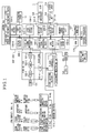
FIG. 1 is a block diagram of a digital camera as an embodiment of an imaging apparatus of the present invention. -
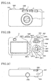
FIG. 2A is a front view of an external view of the digital camera as the embodiment of the imaging apparatus of the present invention. -
FIG. 2B is a back view of the digital camera. -
FIG. 2C is a top view of the digital camera. -
FIG. 3 is an explanatory diagram of a pitch direction and a roll direction of the digital camera as the embodiment of the present invention. -
FIG. 4 is a graph of actual measurement values of a change of a roll angle when a pitch angle increases. -
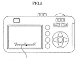
FIG. 5 is a diagram illustrating an example of a display of a digital camera equipped with an electronic level 7. - Hereinafter, referring to drawings, an embodiment of the present invention will be explained. Each reference numeral denotes members and processes of the present invention, and the same reference numerals are used for the same members and processes.
FIGs. 1 ,2A, 2B, 2C are a block diagram and external views of a digital camera as the embodiment using an information device of the present invention.
Firstly, the information device of the present invention will be explained. - The information device of the embodiment includes a digital signal processor (DSP) 104 (corrector), and an acceleration sensor 11 (angle detector). The information device may have a RAM (random access memory) 114, an
internal memory 107, a ROM (read-only memory) 113, and an SDRAM (synchronous dynamic random access memory) 103 other than those above.
A more detailed configuration and operation will be explained later. - An imaging apparatus of the embodiment is equipped with the above information device.
As the imaging apparatus equipped with the information device, the digital camera ofFIG. 2 will be explained by way of example.
As illustrated inFIG. 1 , a CCD (charge-coupled device) 101 is a solid-state image sensor which photoelectrically converts an optical image incident from a lens and the like. An F/E-IC (front/end-IC) 102 includes a CDS (correlated double sampler) 102-1, an AGC (automatic gain controller) 102-2, an A/D (analog/digital converter) 102-3, a TG (timing generator) 102-4. The CDS 102-1 performs a correlated double sampling for an image denoising. The AGC 102-2 performs a gain adjustment. The A/D 102-3 converts an analog signal to a digital signal. The TG 102-4 generates a drive timing signal of the F/E-IC 102. A vertical synchronizing signal (VD signal) and a horizontal synchronizing signal (HD signal) are supplied by a first CCD signal processing block 104-1 in the information device and theCCD 101 is controlled by a CPU (central processing unit) block 104-3. - A
lens barrel unit 4 includes a zoom optical system 4-1, a focus optical system 4-2, an aperture unit 4-3, a mechanical shutter unit 4-4, and a motor driver 4-5. The zoom optical system 4-1 includes a zoom lens 4-1a where an optical image of a photographic subject passes, and a zoom lens drive motor 4-1b. The focus optical system 4-2 includes a focus lens 4-2a, and a focus lens drive motor 4-2b. The aperture unit 4-3 includes an aperture 4-3a, and an aperture drive motor 4-3b. The mechanical shutter unit 4-4 includes a mechanical shutter 4-4a, and a mechanical shutter drive motor 4-4b. The motor driver 4-5 drives each motor. - In the
ROM 113, a control program written in a code readable in the CPU block 104-3 and a control parameter are stored. When the digital camera as the imaging apparatus of the embodiment is turned on, the control program is loaded to a main memory, which is not illustrated, in the information device. The CPU block 104-3 controls the operation of each part of a main body of the imaging apparatus based on the control program, and data and the like which are necessary for control are temporarily stored in a RAM (random access memory) 114 and a local SRAM (static random access memory) 104-4 in theDSP 104. By using a rewritable flash ROM as theROM 108, it is possible to change the control program and the control parameter, and easily upgrade a function. - The DSP 104 includes the first CCD signal processing block 104-1, a second CCD signal processing block 104-2, the CPU block 104-3, the local SRAM 104-4, a USB block 104-5, a serial block 104-6, a JPEG CODEC block 104-7, a RESIZE block 104-8, a TV signal display block 104-9, and a memory card controller block 104-10. The first CCD signal processing block 104-1 receives output data of the F/
E-IC 102 and performs a white balance setting and a gamma setting by use of the output data, and as described above, supplies the VD signal and the HD signal. The second CCD signal processing block 104-2 converts the output data to brightness data and color difference data by a filtering operation. The CPU block 104-3 controls the above-described operations of each part of the apparatus. The local SRAM 104-4 temporarily stores the above-described data and the like which are necessary for control. The USB block 104-5 performs a USB communication with an external device such as a personal computer (PC). The serial block 104-6 performs a serial communication with an external device such as a PC. The JPEG CODEC block 104-7 performs JPEG compression and extension of image data. The RESIZE block 104-8 expands and reduces a size of image data by an interpolation operation. The TV signal display block 104-9 converts image data to a video signal for displaying on an external display device such as a liquid crystal display, a TV (television) and so on. The memory card controller block 104-10 performs a control of a memory card which records shot image data. Each of these blocks is mutually connected via bus lines. - The SDRAM 103 temporarily stores image data, when various processes are performed on image data in the DSP 104. The stored image data, for example, are "RAW-RGB image data", "YUV image data", "JPEG image data" and so on. The RAW-RGB image data is image data which is in a state where the white balance setting and the gamma setting have been performed in the first CCD signal processing block 104-1 after being loaded from the
CCD 101 via the F/E-IC 102. The YUV image data is image data which is in a state where a conversion to brightness data and color difference data has been performed in the second CCD signal processing block 104-2. The JPEG image data is image data which is in a state where the JPEG compression has been performed in the JPEG CODEC block 104-7. Theinternal memory 107 is a memory which is capable of recording shot image data. Thisinternal memory 107 can record the JPEG image data. - An
LCD driver 108 is a drive circuit which drives an LCD (liquid crystal display) 5. And additionally, theLCD driver 108 also has a function of converting the video signal outputted from the TV signal display block 104-9 to a signal for displaying on theLCD 5. TheLCD 5 is a display for monitoring a state of a photographic subject before shooting, checking a shot image, displaying image data recorded in the memory card or theinternal memory 107, and so on. A video AMP (amplifier) 109 is an amplifier which converts an impedance of the video signal outputted from the TV signal display block 104-9 to 75 Ω. Avideo jack 110 is a jack which connects to an external display device such as a TV. An operation key unit SW1 to SW15 is a key circuit which a user operates. A SUB-CPU 105 outputs an output signal of the operation key unit SW1 to SW15 and the like as user's operation information to the CPU block 104-3. TheSUB-CPU 105 communicates with an RTC (real time clock) 112, which keeps track of the current time, and controls time. - An
acceleration sensor 111 is mounted on a printed circuit board (PCB). Theacceleration sensor 111 outputs acceleration data in directions of 2 axes (X and Y axes) in the case of a 2-axis acceleration sensor, and outputs acceleration data in directions of 3 axes (X, Y and Z axes) in the case of a 3-axis acceleration sensor. The output data of theacceleration sensor 111 is inputted in an I2C (inter integrated circuit) block 104-11 of theDSP 104 by a serial communication, and a roll angle and a pitch angle of the imaging apparatus are calculated based on the data. The calculated roll angle and pitch angle are displayed on theLCD 5 or the like. A roll angle θA and a pitch angle ϕ obtained from the acceleration sensor are expressed by the following Formula 1. -

- Here, each of X0, Y0, and Z0 is an output of the acceleration sensor in zero gravity. Formula 1 is a calculation formula of the roll angle and the pitch angle in the case of the 3-axis acceleration sensor, however also in the case of the 2-axis acceleration sensor, the roll angle and the pitch angle can be obtained by use of the same formula as the above. (However, a method for detecting if a value of the pitch angle is positive or negative is needed.)
A method of an angle correction of the embodiment includes a step of an angle detection which outputs data for obtaining a roll angle and a pitch angle of an object, and a step of a correction which corrects the roll angle based on the pitch angle obtained from the data outputted in the step of the angle detection. In following examples, the step of the correction will be explained in detail. - Referring to
FIGs. 2A, 2B, and 2C , each functional component which is installed with the digital camera as the above-described imaging apparatus will be explained.
InFIGs. 2A and 2C , thelens barrel unit 4 is installed in the vicinity of the center of a front surface of a main body of the digital camera, and a flash emitting section 1, adistance measuring unit 2, and anoptical viewfinder 3 are installed in an upper part of the front surface. On a top surface of the main body of the digital camera, a shutter release button SW1, a mode dial SW2, and a first jog dial SW3 are installed.
As illustrated inFIG. 2B , on a back surface of the main body of the digital camera, theLCD 5, a second jog dial SW4, a zoom switch (telephoto) SW5, a zoom switch (wide-angle) SW6, an up-direction indicator switch SW7, a right-direction indicator switch SW8, an OK switch SW9, a left-direction indicator switch SW10, a down-direction indicator switch SW11 which also serves as a macro switch, a display switch SW12, a delete switch SW13, a menu switch SW14, and a power switch SW15 are installed. An eye piece of theoptical viewfinder 3 is disposed on the back surface of the main body of the digital camera. In the present specification, there are some cases where the above-described various switches SW1 to SW15 are collectively called the operation key unit. - Next, a pitch angle and a roll angle of the imaging apparatus (digital camera) will be explained by use of
FIG. 3 . As illustrated inFIG. 3 , an angle in a roll direction (a roll angle) is an angle of rotation about an optical axis of the imaging apparatus (here, the optical axis is taken as a Z axis.), and an angle in a pitch direction (a pitch angle) is an angle of rotation about a horizontal axis of the imaging apparatus (here, the horizontal axis is taken as an X axis). Due to a cross-axis sensitivity and so on, as a pitch angle increases, a roll angle changes. Changes of a roll angle along with changes of a pitch angle are actually measured, and actual measured values are illustrated as a graph inFIG. 4 . InFIG. 4 , a state where a pitch angle ϕ = 0° (0 degrees) and a roll angle θ = 0° (0 degrees) is taken as a reference. As illustrated inFIG. 4 , it is apparent that as a pitch angle ϕ increases, a roll angle θA gradually changes, and a difference of roll angle Δθ increases. In order to solve this problem, two examples will be described. - In a case where the imaging apparatus (digital camera) is equipped with an electronic level 7 (information device) as illustrated in
FIG. 5 , by use of output values (X, Y, and Z) obtained from the acceleration sensor, an angle calculation is performed by the CPU block 104-3 of theDSP 104 via the I2C block 104-11, and a roll angle θA is calculated (Formula 1). A roll angle θA in a state where a pitch angle ϕ = 0° and aroll angle 0 = 0° is taken as a reference, and output values of the acceleration sensor are stored in theROM 113. This is performed on each individual imaging apparatus (digital camera) in a process before shipment. The stored values here are taken as a reference roll angle θ offset0 ... (I).
In a conventional method of a calculation of an angle, a roll angle θA is calculated from Formula 1 by use of output values of the acceleration sensor, and then a roll angle to be corrected θ (correction roll angle θ) is obtained by subtracting the roll angle θ_offset0 from the calculated roll angle θA (correction roll angle θ = θA- θ_offset0).
Additionally, in the embodiment, output values of the acceleration sensor in a case where a pitch angle ϕ which is increased and a roll angle θ = 0° are also stored in theROM 113.
In a case where a correction table is created and an angle correction is performed, output values of the acceleration sensor in four cases, which are a case of a pitch angle ϕ = 15° and a roll angle θ = 0°, a case of a pitch angle ϕ = 30° and a roll angle θ = 0°, a case of a pitch angle ϕ = 45° and a roll angle θ = 0°, and a case of a pitch angle ϕ =60° and a roll angle θ= 0°, are stored in theROM 113. These are taken as reference roll angles θ_offset15 ... (II), θ_offset30 ... (III), θ_offset45 ... (IV), and θ_offset60 ... (V), respectively.
In Table (correction table) 1 below, each of the reference roll angles (I) to (V) is set per range of pitch angle ϕ of the digital camera. And a correction roll angle θ is calculated by use of each of the reference roll angles (I) to (V) stored in theROM 113. -
[Table 1] 0°≦ϕ<15° 15°≦ϕ<30° 30°≦ϕ<45° 45°≦ϕ<60° 60°≦ϕ (I) (II) (III) (IV) (V) - The correction roll angle θ is calculated by subtracting a reference roll angle which is automatically selected based on a pitch angle ϕ (any one of the reference roll angles θ_offset0, θ_offset15, θ_offset30, θ_offset45, and θ_offset60) from a roll angle θA which is calculated from Formula 1. For example, a correction roll angle θ in the case of a pitch angel ϕ = 20° is obtained by subtracting the reference roll angle θ_offset15 in the case of the pitch angle ϕ = 15° from a roll angle θA which is calculated from Formula 1 by use of output values of the acceleration sensor (see Table 1).
- Accuracy improves by use of the method described in Example 1, however tasks increase. In the present example, assuming that a relationship expressed in
FIG. 4 is an approximately linear shape (that is, a proportional relationship), and reference roll angles θ_offset0 and θ_offset45 are calculated from pitch angles ϕ = 0° and 45°, and then a formula calculating a correction roll angle θ expressed by a linear shape is derived from these reference angles θ_offset0 and θ_offset45.
The correction roll angle θ is calculated by use of a roll angle θA which is calculated by use of output values of the acceleration sensor and the above calculated reference roll angles θ_offset0 and θ_offset45 (see Formula 2).
By calculating the correction roll angle θ by use ofFormula 2, it is possible to improve accuracy of a roll angle θ in a case where a pitch angle ϕ is not 0°. In a method of an angle correction of the present example, it is possible to calculate a correction roll angle by a correction formula expressed by a linear shape as described above derived by use of pitch angles obtained from an acceleration sensor as an angle detector, and then correct a roll angle by use of the correction roll angle. - In the above two examples, a case where values of pitch angles ϕ are positive has been explained, however the same is true of a case where values of pitch angles ϕ are negative.
That is, the values of the pitch angles ϕ in a correction table where the values of the pitch angles ϕ are negative and the values of the pitch angles ϕ in Table 1 where the values of the pitch angle ϕ are positive are symmetrical to the pitch angle of 0°. And by use of the correction table, a reference roll angle is automatically selected based on a pitch angle ϕ, and then a roll angle θ is corrected by use of the reference roll angle. - As for the information device of the embodiment, an example that an information device is mounted on an imaging apparatus such as a camera and used has been explained, however the information device also can be mounted on mobile devices (game machine, PDA (personal digital assistance), mobile communication device, in-car image input device, and monitoring device) and the like and used.
- According to the embodiment, it is possible to display a highly-accurate roll angle of an object, for example, an imaging apparatus such as a digital camera.
- Although the present invention has been described in terms of exemplary embodiments, it is not limited thereto. It should be appreciated that variations may be made in the embodiments described by persons skilled in the art without departing from the scope of the present invention as defined by the following claims.
- The present application is based on claims from Japanese patent application number
2009-161603, filed July 8, 2009
Claims (11)
- An information device (7), comprising:an angle detector (111) which outputs data for obtaining a roll angle and a pitch angle of an object; anda corrector (104) which corrects the roll angle based on the pitch angle obtained from the data outputted by the angle detector (111).
- The information device (7) according to claim 1, comprising:a correction table in which a reference roll angle used for a correction of the roll angle is set per range of a pitch angle,
wherein the corrector (104) automatically selects the reference roll angle based on the pitch angle by use of the correction table. - The information device (7) according to claim 2, wherein values in the correction table are symmetrical to a pitch angle of 0°.
- The information device (7) according to any one of claims 1 to 3, wherein the corrector (104) calculates a correction roll angle by a correction formula expressed by a linear shape which is derived by pitch angles obtained from the data outputted by the angle detector (111), and corrects the roll angle by use of the calculated correction roll angle.
- The information device (7) according to any one of claims 1 to 4, wherein the angle detector (111) is a 2-axis acceleration sensor or a 3-axis acceleration sensor.
- A digital camera, which is an object, comprising:an information device (7) according to any one of claims 1 to 5.
- A method of an angle correction of an object, comprising:a step of an angle detection which outputs data for obtaining a roll angle and a pitch angle of the object; anda step of a correction which corrects the roll angle based on the pitch angle obtained from the data outputted in the step of the angle detection.
- The method of the angle correction according to claim 7, wherein in the step of the correction, a correction table in which a reference roll angle used for a correction of the roll angle is set per range of a pitch angle is used, and a reference roll angle is selected based on the pitch angle.
- The method of the angle correction according to claim 8, wherein values in the correction table are symmetrical to a pitch angle of 0°.
- The method of the angle correction according to any one of claims 7 to 9, wherein the step of the correction calculates a correction roll angle by a correction formula expressed by a linear shape which is derived by pitch angles obtained from the data outputted in the step of the angle detection, and corrects the roll angle by use of the calculated correction roll angle.
- The method of the angle correction according to any one of claims 7 to 10, wherein in the step of the angle detection, a 2-axis acceleration sensor or a 3-axis acceleration sensor is used.
Applications Claiming Priority (1)
| Application Number | Priority Date | Filing Date | Title |
|---|---|---|---|
| JP2009161603A JP2011019035A (en) | 2009-07-08 | 2009-07-08 | Information device, imaging apparatus having the same, and method of angle correction |
Publications (1)
| Publication Number | Publication Date |
|---|---|
| EP2284487A1 true EP2284487A1 (en) | 2011-02-16 |
Family
ID=42738901
Family Applications (1)
| Application Number | Title | Priority Date | Filing Date |
|---|---|---|---|
| EP10251181A Ceased EP2284487A1 (en) | 2009-07-08 | 2010-06-30 | Information device, imaging apparatus having the same, and method of angle correction of object |
Country Status (3)
| Country | Link |
|---|---|
| US (1) | US8599272B2 (en) |
| EP (1) | EP2284487A1 (en) |
| JP (1) | JP2011019035A (en) |
Families Citing this family (5)
| Publication number | Priority date | Publication date | Assignee | Title |
|---|---|---|---|---|
| EP2787598B1 (en) * | 2011-11-28 | 2018-04-25 | Kyocera Corporation | Power control device, power control system, and power control method |
| CN104704804B (en) * | 2013-01-24 | 2018-05-18 | 松下知识产权经营株式会社 | Photographic device, detection device |
| TWI558588B (en) * | 2014-04-09 | 2016-11-21 | Papago Inc | Driving Recorder with Correcting Shooting Pose and Its Correction |
| JP6760311B2 (en) | 2016-02-09 | 2020-09-23 | 株式会社リコー | Image display device, in-vehicle system and image display method |
| CN111189432B (en) * | 2020-01-10 | 2021-08-13 | 湖北三江航天红峰控制有限公司 | A dual-axis inclinometer calculation method |
Citations (4)
| Publication number | Priority date | Publication date | Assignee | Title |
|---|---|---|---|---|
| US6164117A (en) * | 1999-01-22 | 2000-12-26 | Caterpillar Inc. | Inclination sensor and method of measuring the accuracy thereof |
| US20040007064A1 (en) * | 2002-07-10 | 2004-01-15 | Hitachi Metals, Ltd. | Acceleration measuring apparatus with calibration function |
| US20090096910A1 (en) * | 2007-09-19 | 2009-04-16 | Yasuda Takuroh | Imaging apparatus |
| JP2009094987A (en) | 2007-09-19 | 2009-04-30 | Ricoh Co Ltd | Imaging device |
Family Cites Families (16)
| Publication number | Priority date | Publication date | Assignee | Title |
|---|---|---|---|---|
| US20030158699A1 (en) * | 1998-12-09 | 2003-08-21 | Christopher P. Townsend | Orientation sensor |
| DE69904759T2 (en) * | 1998-12-17 | 2003-09-25 | Nec Tokin Corp | ORIENTATION ANGLE DETECTOR |
| US7554578B2 (en) * | 2000-07-11 | 2009-06-30 | Phase One A/S | Digital camera with integrated accelerometers |
| JP2004085476A (en) * | 2002-08-28 | 2004-03-18 | Sony Corp | Head tracking method and apparatus |
| KR100565794B1 (en) * | 2003-12-30 | 2006-03-29 | 삼성전자주식회사 | Geomagnetic sensor for calculating the azimuth angle by compensating the influence of tilt, and its calculation method |
| KR100594971B1 (en) * | 2004-01-09 | 2006-06-30 | 삼성전자주식회사 | Input device using geomagnetic sensor and input signal generation method using same |
| US7395987B2 (en) * | 2005-07-26 | 2008-07-08 | Honeywell International Inc. | Apparatus and appertaining method for upfinding in spinning projectiles using a phase-lock-loop or correlator mechanism |
| KR100799536B1 (en) * | 2005-11-08 | 2008-01-31 | 한국전자통신연구원 | Virtual axis magnetic field data estimating apparatus and method for compensating tilt angle error of two-axis geomagnetic field sensor, and azimuth angle calculation system using the same |
| KR100655937B1 (en) * | 2005-11-25 | 2006-12-11 | 삼성전자주식회사 | Geomagnetic sensor and method for calculating azimuth |
| KR100653081B1 (en) * | 2005-11-25 | 2006-12-04 | 삼성전자주식회사 | Geomagnetic sensor and its azimuth calculation method |
| JP4811173B2 (en) * | 2006-07-28 | 2011-11-09 | 日本電気株式会社 | Portable terminal device, timer control method, and timer control program |
| TWI423665B (en) * | 2006-10-10 | 2014-01-11 | Pentax Ricoh Imaging Co Ltd | Angular velocity detection apparatus |
| JP5106015B2 (en) * | 2006-10-10 | 2012-12-26 | ペンタックスリコーイメージング株式会社 | Angular velocity detector |
| JP2008151822A (en) * | 2006-12-14 | 2008-07-03 | Pentax Corp | Image blur correction device |
| WO2009011105A1 (en) * | 2007-07-13 | 2009-01-22 | Panasonic Corporation | Imaging device |
| JP5244579B2 (en) * | 2008-12-25 | 2013-07-24 | ペンタックスリコーイメージング株式会社 | Imaging device |
-
2009
- 2009-07-08 JP JP2009161603A patent/JP2011019035A/en active Pending
-
2010
- 2010-06-28 US US12/824,333 patent/US8599272B2/en not_active Expired - Fee Related
- 2010-06-30 EP EP10251181A patent/EP2284487A1/en not_active Ceased
Patent Citations (4)
| Publication number | Priority date | Publication date | Assignee | Title |
|---|---|---|---|---|
| US6164117A (en) * | 1999-01-22 | 2000-12-26 | Caterpillar Inc. | Inclination sensor and method of measuring the accuracy thereof |
| US20040007064A1 (en) * | 2002-07-10 | 2004-01-15 | Hitachi Metals, Ltd. | Acceleration measuring apparatus with calibration function |
| US20090096910A1 (en) * | 2007-09-19 | 2009-04-16 | Yasuda Takuroh | Imaging apparatus |
| JP2009094987A (en) | 2007-09-19 | 2009-04-30 | Ricoh Co Ltd | Imaging device |
Also Published As
| Publication number | Publication date |
|---|---|
| US20110007169A1 (en) | 2011-01-13 |
| JP2011019035A (en) | 2011-01-27 |
| US8599272B2 (en) | 2013-12-03 |
Similar Documents
| Publication | Publication Date | Title |
|---|---|---|
| JP6954414B2 (en) | Imaging device | |
| CN101766021B (en) | Imaging apparatus and a control method of the imaging apparatus | |
| US8542279B2 (en) | Image capturing apparatus | |
| US20060170784A1 (en) | Image capturing device, correction device, mobile phone, and correcting method | |
| TWI757387B (en) | Method for calibrating driving amount of actuator configured to correct blurring of image taken by camera | |
| US10198796B2 (en) | Information processing apparatus, control method of information processing apparatus, and non-transitory storage medium storing information processing program | |
| US8599272B2 (en) | Imaging apparatus with roll angle correction and method of angle correction of object | |
| JP5648487B2 (en) | Imaging device | |
| US20200342618A1 (en) | Image capturing apparatus and control method thereof, and orientation angle calculation apparatus | |
| JP2009147863A (en) | Electronic device and its attitude angle display method | |
| US9270884B2 (en) | Imaging apparatus and detecting apparatus | |
| JP4939451B2 (en) | Imaging device and method of correcting angle information of imaging device | |
| JP2019028192A (en) | Imaging device | |
| JP2012054899A (en) | Imaging apparatus and posture detection method | |
| JP5489607B2 (en) | Imaging device | |
| KR20120079664A (en) | A method correcting image's level and a camera device using the same | |
| JP2009141868A (en) | Imaging device | |
| JP2012095207A (en) | Imaging device, optical instrument, and method for correcting output of acceleration sensor provided in the imaging device or optical instrument | |
| JP2011059345A (en) | Imaging apparatus |
Legal Events
| Date | Code | Title | Description |
|---|---|---|---|
| PUAI | Public reference made under article 153(3) epc to a published international application that has entered the european phase |
Free format text: ORIGINAL CODE: 0009012 |
|
| 17P | Request for examination filed |
Effective date: 20100726 |
|
| AK | Designated contracting states |
Kind code of ref document: A1 Designated state(s): AL AT BE BG CH CY CZ DE DK EE ES FI FR GB GR HR HU IE IS IT LI LT LU LV MC MK MT NL NO PL PT RO SE SI SK SM TR |
|
| AX | Request for extension of the european patent |
Extension state: BA ME RS |
|
| 17Q | First examination report despatched |
Effective date: 20120119 |
|
| STAA | Information on the status of an ep patent application or granted ep patent |
Free format text: STATUS: THE APPLICATION HAS BEEN REFUSED |
|
| 18R | Application refused |
Effective date: 20130613 |