EP2284441A2 - Burner of a gas turbine - Google Patents
Burner of a gas turbine Download PDFInfo
- Publication number
- EP2284441A2 EP2284441A2 EP10167953A EP10167953A EP2284441A2 EP 2284441 A2 EP2284441 A2 EP 2284441A2 EP 10167953 A EP10167953 A EP 10167953A EP 10167953 A EP10167953 A EP 10167953A EP 2284441 A2 EP2284441 A2 EP 2284441A2
- Authority
- EP
- European Patent Office
- Prior art keywords
- nozzle
- burner
- cone shaped
- shaped chamber
- lance
- Prior art date
- Legal status (The legal status is an assumption and is not a legal conclusion. Google has not performed a legal analysis and makes no representation as to the accuracy of the status listed.)
- Withdrawn
Links
Images


Classifications
-
- F—MECHANICAL ENGINEERING; LIGHTING; HEATING; WEAPONS; BLASTING
- F23—COMBUSTION APPARATUS; COMBUSTION PROCESSES
- F23D—BURNERS
- F23D11/00—Burners using a direct spraying action of liquid droplets or vaporised liquid into the combustion space
- F23D11/36—Details
- F23D11/38—Nozzles; Cleaning devices therefor
-
- F—MECHANICAL ENGINEERING; LIGHTING; HEATING; WEAPONS; BLASTING
- F23—COMBUSTION APPARATUS; COMBUSTION PROCESSES
- F23D—BURNERS
- F23D17/00—Burners for combustion simultaneously or alternately of gaseous or liquid or pulverulent fuel
- F23D17/002—Burners for combustion simultaneously or alternately of gaseous or liquid or pulverulent fuel gaseous or liquid fuel
-
- F—MECHANICAL ENGINEERING; LIGHTING; HEATING; WEAPONS; BLASTING
- F23—COMBUSTION APPARATUS; COMBUSTION PROCESSES
- F23R—GENERATING COMBUSTION PRODUCTS OF HIGH PRESSURE OR HIGH VELOCITY, e.g. GAS-TURBINE COMBUSTION CHAMBERS
- F23R3/00—Continuous combustion chambers using liquid or gaseous fuel
- F23R3/28—Continuous combustion chambers using liquid or gaseous fuel characterised by the fuel supply
- F23R3/286—Continuous combustion chambers using liquid or gaseous fuel characterised by the fuel supply having fuel-air premixing devices
-
- F—MECHANICAL ENGINEERING; LIGHTING; HEATING; WEAPONS; BLASTING
- F23—COMBUSTION APPARATUS; COMBUSTION PROCESSES
- F23C—METHODS OR APPARATUS FOR COMBUSTION USING FLUID FUEL OR SOLID FUEL SUSPENDED IN A CARRIER GAS OR AIR
- F23C2900/00—Special features of, or arrangements for combustion apparatus using fluid fuels or solid fuels suspended in air; Combustion processes therefor
- F23C2900/07002—Premix burners with air inlet slots obtained between offset curved wall surfaces, e.g. double cone burners
-
- F—MECHANICAL ENGINEERING; LIGHTING; HEATING; WEAPONS; BLASTING
- F23—COMBUSTION APPARATUS; COMBUSTION PROCESSES
- F23C—METHODS OR APPARATUS FOR COMBUSTION USING FLUID FUEL OR SOLID FUEL SUSPENDED IN A CARRIER GAS OR AIR
- F23C2900/00—Special features of, or arrangements for combustion apparatus using fluid fuels or solid fuels suspended in air; Combustion processes therefor
- F23C2900/07021—Details of lances
-
- F—MECHANICAL ENGINEERING; LIGHTING; HEATING; WEAPONS; BLASTING
- F23—COMBUSTION APPARATUS; COMBUSTION PROCESSES
- F23R—GENERATING COMBUSTION PRODUCTS OF HIGH PRESSURE OR HIGH VELOCITY, e.g. GAS-TURBINE COMBUSTION CHAMBERS
- F23R2900/00—Special features of, or arrangements for continuous combustion chambers; Combustion processes therefor
- F23R2900/00014—Reducing thermo-acoustic vibrations by passive means, e.g. by Helmholtz resonators
Definitions
- the present invention relates to a burner of a gas turbine.
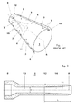
- Figure 1 shows a traditional burner. This burner has a cone shaped chamber 1 defined by two part cone shells 2 wherein air 3 is introduced through slots 4.
- the air generates in the centre of the cone shaped chamber 1 (i.e. along the axis 5 of the cone shaped chamber 1) a zone of larger vortices 6 (the vortex core).
- a lance 8 is provided along the axis 5 to inject a thin liquid fuel jet 15 into the cone shaped chamber 1; in particular the liquid fuel jet 15 is injected into the vortex core 6 to mix with the air and form a combustible mixture.
- liquid fuel jet cross section when the liquid fuel jet cross section is too small, it withstands large asymmetrical centrifugal forces since liquid fuel jet can not reliably stay within the equally small vortex core and misses the centre, with large gradients of circumferential velocity, which then prevent it from staying at the vortex core; in practice during operation the liquid fuel jet 15 fluctuates radially around the vortex core.
- Combustion instabilities can influence both the lifetime and noise emissions.
- Burners having a lance with a divergent outlet are also known.
- WO03/054447 discloses a lance having a tip with a diverging portion and a diverter facing it; the diffuser angle is very large and also thanks to the diverter the fuel jet is diverted laterally generating a conical fuel flow.
- US2003/150217 discloses a lance with a very large conical tip arranged to fan out the fuel after injection.
- DE19537636 discloses a lance with a very short diverging portion with a wide diverging angle; this diverging portion is arranged to generate a conical fuel flow.
- EP692675 and DE4446609 disclose a lance having a cylindrical end that feeds the fuel in a conical atomisation chamber wherein atomisation air is injected; the mixture formed in the atomisation chamber is then fed to a conical burner chamber.
- the lance does not inject a liquid jet (in the form of a liquid cylinder) into the vortex core.
- the technical aim of the present invention is therefore to provide a burner of a gas turbine by which the said problems of the known art are eliminated or sensibly reduced.
- an aspect of the invention is to provide a burner with which combustion instabilities are limited and thus noise, in particular low frequency noise, is reduced.
- a further aspect of the invention is to provide a burner in which a liquid fuel jet is injected into the vortex core.
- Another aspect of the invention is to provide a burner having a longer lifetime with respect to traditional burners.
- the burner in embodiments of the invention has a lance with a small angle with defined proportions that allows a liquid jet to be generated that has a cross section larger than the cross section of the passage defined by the lance, but does not open forming a fuel cone.
- This allows a lance having small cross section to be manufactured, increasing easy of assembling and reducing lance complexity.
- the structure of the burner is similar to that already described and, in this respect, it has two part cone shells 2 arranged offset with respect to one another and defining a cone shaped chamber 1.
- the cone shaped chamber 1 has two longitudinal tangential slots 4 for feeding air 3, and a lance 8 arranged along the axis 5 for feeding a liquid fuel.
- the lance 8 faces the cone shaped chamber 1 directly, i.e. without any component inbetween and is arranged to inject a liquid jet (i.e. in the form of a liquid cylinder).
- the burner may also have more than two part cone shells.
- the cone shells are also provided with nozzles 10 arranged on each of the cone shell, close to the tangential slots 4, to inject gaseous fuel into the cone shaped chamber 1.
- cone shells 2 are housed in a plenum (not shown) wherein compressed air coming from the compressor of the gas turbine (not shown) is fed, this air enters through the tangential slots 4 into the cone shaped chamber 1; downstream of the cone shaped chamber 1 a combustion chamber (not shown) is provided.
- the lance 8 carries a liquid fuel nozzle 12 arranged centrally in the cone shaped chamber 1, i.e. a longitudinal axis of the nozzle 12 overlaps the axis 5.
- the axis of the lance 8 is the same as the axis of the nozzle 12 and it is also the same as the axis 5 of the cone shaped chamber 1.
- the nozzle 12 has a first portion 13 with a constant diameter D and, downstream of it, a second portion 14, facing the cone shaped chamber 1, that is divergent in shape.
- the diverging portion 14 of the nozzle 12 has a diffuser angle ⁇ (i.e. an angle between the wall of the nozzle and the axis 5) of less than 5° and greater than 0°; preferably the diffuser angle ⁇ is comprised between 1.5-2.2; in other embodiments the diffuser angle ⁇ is between 2-4°.
- ⁇ i.e. an angle between the wall of the nozzle and the axis 5
- the diverging portion 14 of the nozzle 12 has a diffuser length L to nozzle diameter D ratio comprised between 2-6, preferably between 3-5 and more preferably about 4, wherein the diffuser length L is the length of the diverging portion 14 of the nozzle 12 and the nozzle diameter D is the smaller diameter of the diverging portion 14 (i.e. the diameter D of the first portion 13 of the nozzle 12).
- the burner may operate with gaseous fuel and liquid fuel.
- the diverging portion 14 when the liquid fuel goes out from the nozzle 12 it forms a liquid jet 15 having a thickness (i.e. a diameter) larger than the smaller diameter of the diverging portion 14 and also larger than the greater diameter of the diverging portion 14 (i.e. the diameter of the terminal portion of the diverging portion 14), but it does not open forming a conical surface; in other words the liquid fuel forms a liquid jet that is substantially cylindrical with a cross section larger than the largest inner cross section of the nozzle.
- the diameter of the liquid jet 15 is large (in particular larger than in traditional burners), when the liquid fuel jet 15 enters the vortex core 6 it is subjected to substantially symmetrical centrifugal forces that do not urge it outside of the vortex core 6.
- liquid jet 15 stays within the vortex core 6 without radial fluctuations, limiting in particular low frequency combustion instabilities and low frequency noise.
- the burner of the invention also has sensibly reduced NO x emissions and smoke emissions.
- the improved combustion stability allows an extended lifetime to be achieved.
- Tests were performed to ascertain the operation of a combustion chamber having a lance in embodiments of the invention.
Landscapes
- Engineering & Computer Science (AREA)
- Chemical & Material Sciences (AREA)
- Combustion & Propulsion (AREA)
- Mechanical Engineering (AREA)
- General Engineering & Computer Science (AREA)
- Spray-Type Burners (AREA)
- Nozzles For Spraying Of Liquid Fuel (AREA)
Abstract
Description
- The present invention relates to a burner of a gas turbine.
-
Figure 1 shows a traditional burner. This burner has a coneshaped chamber 1 defined by twopart cone shells 2 whereinair 3 is introduced throughslots 4. - The air generates in the centre of the cone shaped chamber 1 (i.e. along the
axis 5 of the cone shaped chamber 1) a zone of larger vortices 6 (the vortex core). - A lance 8 is provided along the
axis 5 to inject a thinliquid fuel jet 15 into the coneshaped chamber 1; in particular theliquid fuel jet 15 is injected into thevortex core 6 to mix with the air and form a combustible mixture. - Nevertheless, when the liquid fuel jet cross section is too small, it withstands large asymmetrical centrifugal forces since liquid fuel jet can not reliably stay within the equally small vortex core and misses the centre, with large gradients of circumferential velocity, which then prevent it from staying at the vortex core; in practice during operation the
liquid fuel jet 15 fluctuates radially around the vortex core. - These fluctuations lead to combustion instabilities that are amplified in the burner and combustion chamber downstream of the burner.
-
US 6,270,338 describes a burner of a gas turbine having these features. - Combustion instabilities can influence both the lifetime and noise emissions.
- In particular, low frequency instabilities with a frequency less than 30 Hz are difficult to deal with.
- In fact, from the one side it is not possible to suppress these instabilities with operation changes, and from the other side it is not possible damping of these low frequencies instabilities using for example Helmholtz dampers, because of the huge resonator volumes that would be required.
- These problems are also increased by the fact that low frequency pulsations couple the exhaust system, that amplifies the noise and propagate it into the neighbouring areas of the power plant.
- Burners having a lance with a divergent outlet are also known.
- In this respect,
WO03/054447 -
US2003/150217 discloses a lance with a very large conical tip arranged to fan out the fuel after injection. -
DE19537636 discloses a lance with a very short diverging portion with a wide diverging angle; this diverging portion is arranged to generate a conical fuel flow. -
EP692675 DE4446609 disclose a lance having a cylindrical end that feeds the fuel in a conical atomisation chamber wherein atomisation air is injected; the mixture formed in the atomisation chamber is then fed to a conical burner chamber. - In these burners the lance does not inject a liquid jet (in the form of a liquid cylinder) into the vortex core.
- The technical aim of the present invention is therefore to provide a burner of a gas turbine by which the said problems of the known art are eliminated or sensibly reduced.
- Within the scope of this technical aim, an aspect of the invention is to provide a burner with which combustion instabilities are limited and thus noise, in particular low frequency noise, is reduced.
- A further aspect of the invention is to provide a burner in which a liquid fuel jet is injected into the vortex core.
- Another aspect of the invention is to provide a burner having a longer lifetime with respect to traditional burners.
- The technical aim, together with these and further aspects, are attained according to the invention by providing a burner in accordance with the accompanying claims.
- Advantageously, the burner in embodiments of the invention has a lance with a small angle with defined proportions that allows a liquid jet to be generated that has a cross section larger than the cross section of the passage defined by the lance, but does not open forming a fuel cone. This allows a lance having small cross section to be manufactured, increasing easy of assembling and reducing lance complexity.
- Further characteristics and advantages of the invention will be more apparent from the description of a preferred but non-exclusive embodiment of the burner according to the invention, illustrated by way of nonlimiting example in the accompanying drawings, in which:
-
Figure 1 is a schematic view of a burner with a cone shaped chamber according to the prior art; -
Figure 2 shows a nozzle of the lance according to the invention; -
Figure 3 shows a particular of the nozzle offigure 2 and a liquid fuel jet injected through it; -
Figure 4 is a schematic view of a burner with a cone shaped chamber according to an embodiment of the invention; -
Figures 5 and 6 are respectively a diagram showing the pulsations in a traditional combustion chamber and in a combustion chamber having the lance in embodiments of the invention; -
Figure 7 shows a diagram indicative of the water flow injected into the combustion chamber and the NOx generated respectively with a traditional combustion chamber and a combustion chamber having a lance in embodiments of the invention; -
Figure 8 shows a diagram indicative of the smoke generated respectively with a traditional combustion chamber and a combustion chamber having a lance in embodiments of the invention; -
Figure 9 shows a diagram indicative of the noise generated respectively with a traditional combustion chamber and a combustion chamber having a lance in embodiments of the invention. - With reference to the figures, these schematically show a burner of a gas turbine.
- The structure of the burner is similar to that already described and, in this respect, it has two
part cone shells 2 arranged offset with respect to one another and defining a cone shapedchamber 1. The coneshaped chamber 1 has two longitudinaltangential slots 4 for feedingair 3, and a lance 8 arranged along theaxis 5 for feeding a liquid fuel. The lance 8 faces the coneshaped chamber 1 directly, i.e. without any component inbetween and is arranged to inject a liquid jet (i.e. in the form of a liquid cylinder). - Naturally also different embodiments of the invention are possible and, in this respect, the burner may also have more than two part cone shells.
- As known in the art, the cone shells are also provided with
nozzles 10 arranged on each of the cone shell, close to thetangential slots 4, to inject gaseous fuel into the coneshaped chamber 1. - In addition, the
cone shells 2 are housed in a plenum (not shown) wherein compressed air coming from the compressor of the gas turbine (not shown) is fed, this air enters through thetangential slots 4 into the coneshaped chamber 1; downstream of the cone shaped chamber 1 a combustion chamber (not shown) is provided. - The lance 8 carries a
liquid fuel nozzle 12 arranged centrally in the coneshaped chamber 1, i.e. a longitudinal axis of thenozzle 12 overlaps theaxis 5. - Preferably the axis of the lance 8 is the same as the axis of the
nozzle 12 and it is also the same as theaxis 5 of the coneshaped chamber 1. - The
nozzle 12 has afirst portion 13 with a constant diameter D and, downstream of it, asecond portion 14, facing the coneshaped chamber 1, that is divergent in shape. - The diverging
portion 14 of thenozzle 12 has a diffuser angle α (i.e. an angle between the wall of the nozzle and the axis 5) of less than 5° and greater than 0°; preferably the diffuser angle α is comprised between 1.5-2.2; in other embodiments the diffuser angle α is between 2-4°. - In addition, the diverging
portion 14 of thenozzle 12 has a diffuser length L to nozzle diameter D ratio comprised between 2-6, preferably between 3-5 and more preferably about 4, wherein the diffuser length L is the length of the divergingportion 14 of thenozzle 12 and the nozzle diameter D is the smaller diameter of the diverging portion 14 (i.e. the diameter D of thefirst portion 13 of the nozzle 12). - The operation of the burner of the invention is apparent from what described and illustrated and is substantially the following.
- The burner may operate with gaseous fuel and liquid fuel.
- During operation with gaseous fuel air is injected through the
tangential slots 4 and gaseous fuel through thenozzles 10; this operation occurs in a traditional way. - During operation with liquid fuel, air is introduced into the cone
shaped chamber 1 through theslots 4 and liquid fuel is injected through thenozzle 12 at the tip of the lance 8. - Because of the diverging
portion 14, when the liquid fuel goes out from thenozzle 12 it forms aliquid jet 15 having a thickness (i.e. a diameter) larger than the smaller diameter of the divergingportion 14 and also larger than the greater diameter of the diverging portion 14 (i.e. the diameter of the terminal portion of the diverging portion 14), but it does not open forming a conical surface; in other words the liquid fuel forms a liquid jet that is substantially cylindrical with a cross section larger than the largest inner cross section of the nozzle. - Since the diameter of the
liquid jet 15 is large (in particular larger than in traditional burners), when theliquid fuel jet 15 enters thevortex core 6 it is subjected to substantially symmetrical centrifugal forces that do not urge it outside of thevortex core 6. - Consequently the
liquid jet 15 stays within thevortex core 6 without radial fluctuations, limiting in particular low frequency combustion instabilities and low frequency noise. - In addition, thanks to the diverging
portion 14, immediately outside of the nozzle 12 a number of liquid fuel drops start to separate from theliquid fuel jet 15, generating alarge zone 17 made of liquid fuel drops and vapour fuel (the vapour being the liquid already evaporated); this zone improves mixing of the fuel with air and limits combustion instabilities (and in particular low frequency instabilities) and noise (in particular low frequency noise). - Advantageously, thanks to the mixing improvement of the liquid fuel and air, the burner of the invention also has sensibly reduced NOx emissions and smoke emissions.
- Moreover, the improved combustion stability allows an extended lifetime to be achieved.
- Tests were performed to ascertain the operation of a combustion chamber having a lance in embodiments of the invention.
- In particular the lance used during the tests has these features:
- L/D=4
- D=3.2 millimeters
- α=2
- the results of those tests are shown in
figures 5 through 9 . -
Figure 5 shows the operation of a gas turbine with a combustion chamber having a traditional lance; this figures shows that large pulsations are generated at 30 Hz; these pulsations are very detrimental for the gas turbine operation since they couple the exhaust system and generate large noise. -
Figure 6 shows the operation of a gas turbine with a combustion chamber having the lance above described. It is evident that in this case pulsations at 30 Hz are severely damped; in contrast pulsations at about 80 Hz are increased, but these pulsations are not detrimental for the gas turbine operation, because they are naturally damped by the exhaust system. In other words, the pulsation peak is shifted from a troubling frequency (i.e. about 30 Hz) to a not troubling frequency (i.e. about 80 Hz). -
Figure 7 shows that with a combustion chamber having a lance in embodiments of the invention the amount of water to be injected into the combustion chamber during gas turbine operation (curve A) is much lower than the amount of water to be injected with gas turbine having a traditional lance (curve B) for given NOx emissions. This allows a cheaper operation, in particular in zones where water is expensive, or allows a NOx emission reduction (in this drawing line C indicates the NOx limit allowed). In this figure on the ordinate the NOx emissions are plotted and on the abscissa Omega identifies the ratio between injected water and liquid fuel mass flow (oil mass flow). -
Figure 8 shows that the gas turbine with the lance in embodiments of the invention also has reduced smoke emissions or reduced water consumption. In particular curve S indicates the smoke generated by gas turbines having a traditional lance, whereas curve E indicates the smoke generated by gas turbines having a lance in embodiments of the invention; (in this drawing line F indicates the smoke limit allowed).Values 0 through 7 on the ordinate are indicative of the amount of smoke generated;level 0 corresponds to no visible smoke andlevels 1 through 7 correspond to increasing smoke. On the abscissa Omega identifies the ratio between injected water and liquid fuel mass flow (oil mass flow). -
Figure 9 indicates the noise generated by a gas turbine with a traditional lance (curve G) and a gas turbine having a combustion chamber with a lance in embodiments of the invention (curve H). On the ordinate there is indicated the noise (in decibel) and on the abscissa Omega identifies the ratio between injected water and liquid fuel mass flow (oil mass flow). From this figure it appears that the noise generated in gas turbine with the lance in embodiments of the invention is much lower than in traditional gas turbines having traditional lances (on the ordinate there is a logarithmic scale) or that for a given noise level the amount of water injected may be reduced. - Naturally the features described may be independently provided from one another.
- In practice the materials used and the dimensions can be chosen according to the requirements and the state of the art.
-
- 1
- cone shaped chamber
- 2
- part cone shell
- 3
- air
- 4
- tangential slot
- 5
- longitudinal axis of the cone shaped chamber
- 6
- vortex core
- 8
- lance
- 10
- gaseous fuel nozzle
- 12
- liquid fuel nozzle
- 13
- first portion of the
nozzle 12 - 14
- diverging portion of the
nozzle 12 - 15
- liquid jet
- 17
- zone encircling the
jet 15 made of liquid fuel drops and vapor fuel - α
- diffuser angle
- D
- nozzle diameter
- L
- diffuser length
- A
- NOx/Omega relationship with burners having traditional lances
- B
- NOx/Omega relationship with burners having lances in embodiments of the invention
- C
- NOx limit allowed
- S
- smoke/Omega relationship with burners having traditional lances
- E
- smoke/Omega relationship with burners having lances in embodiments of the invention
- F
- smoke limit allowed
- G
- noise/Omega relationship with burners having traditional lances
- H
- noise/Omega relationship with burners having lances in embodiments of the invention
Claims (6)
- Burner of a gas turbine comprising at least two part cone shells (2) arranged offset with respect to one another and defining a cone shaped chamber (1) with longitudinal tangential slots (4) for feeding air (3) therein, and a lance (8) carrying at least a liquid fuel nozzle (12) arranged centrally in the cone shaped chamber (1), wherein a portion (14) of the nozzle (12) facing the cone shaped chamber (1) is divergent in shape, characterised in that a diffuser angle (α) between the wall of the nozzle and a longitudinal axis of the cone shaped chamber (1) is less than 5°, and the diverging portion of the nozzle has a diffuser length (L) to nozzle diameter (D) ratio comprised between 2-6, wherein the nozzle diameter (D) is the smaller diameter of the diverging portion (14).
- Burner as claimed in claim 1, characterised in that the diffuser angle (α) is greater than 0°.
- Burner as claimed in claim 1, characterised in that the diverging portion (14) of the nozzle (12) has a diffuser angle (α) comprised between 1.5-2.2.
- Burner as claimed in claim 1, characterised in that the diverging portion (14) of the nozzle (12) has a diffuser angle (α) comprised between 2-4°.
- Burner as claimed in claim 1, characterised in that the diverging portion of the nozzle has a diffuser length (L) to nozzle diameter (D) ratio comprised between 3-5 and preferably about 4.
- Burner as claimed in claim 1, characterised in that the nozzle (12) comprises a first portion (13) with a constant diameter upstream of the diverging portion (14).
Priority Applications (1)
| Application Number | Priority Date | Filing Date | Title |
|---|---|---|---|
| EP10167953.8A EP2284441A3 (en) | 2009-07-30 | 2010-06-30 | Burner of a gas turbine |
Applications Claiming Priority (2)
| Application Number | Priority Date | Filing Date | Title |
|---|---|---|---|
| EP09166907A EP2282115A1 (en) | 2009-07-30 | 2009-07-30 | Burner of a gas turbine |
| EP10167953.8A EP2284441A3 (en) | 2009-07-30 | 2010-06-30 | Burner of a gas turbine |
Publications (2)
| Publication Number | Publication Date |
|---|---|
| EP2284441A2 true EP2284441A2 (en) | 2011-02-16 |
| EP2284441A3 EP2284441A3 (en) | 2014-12-17 |
Family
ID=41393485
Family Applications (2)
| Application Number | Title | Priority Date | Filing Date |
|---|---|---|---|
| EP09166907A Withdrawn EP2282115A1 (en) | 2009-07-30 | 2009-07-30 | Burner of a gas turbine |
| EP10167953.8A Withdrawn EP2284441A3 (en) | 2009-07-30 | 2010-06-30 | Burner of a gas turbine |
Family Applications Before (1)
| Application Number | Title | Priority Date | Filing Date |
|---|---|---|---|
| EP09166907A Withdrawn EP2282115A1 (en) | 2009-07-30 | 2009-07-30 | Burner of a gas turbine |
Country Status (3)
| Country | Link |
|---|---|
| US (1) | US9435532B2 (en) |
| EP (2) | EP2282115A1 (en) |
| AU (1) | AU2010202846B2 (en) |
Families Citing this family (4)
| Publication number | Priority date | Publication date | Assignee | Title |
|---|---|---|---|---|
| US9296038B2 (en) * | 2011-12-29 | 2016-03-29 | Solar Turbines Incorporated | Method and apparatus for swaged liquid injector spoke |
| JP7044669B2 (en) * | 2018-09-05 | 2022-03-30 | 三菱重工業株式会社 | Gas turbine combustor |
| WO2020087154A1 (en) * | 2018-10-30 | 2020-05-07 | Questor Technology Inc. | Low-pressure gas burner |
| CN114508768A (en) * | 2022-01-13 | 2022-05-17 | 南京航空航天大学 | Aviation gas turbine combustion chamber with vortex control diffuser |
Citations (6)
| Publication number | Priority date | Publication date | Assignee | Title |
|---|---|---|---|---|
| EP0692675A2 (en) | 1994-07-13 | 1996-01-17 | Abb Research Ltd. | Method and device for operating a combined burner for liquid and gaseous fuels |
| DE4446609A1 (en) | 1994-12-24 | 1996-06-27 | Abb Management Ag | Fuel feed device for oil- or gas-fired burner for gas turbine |
| DE19537636A1 (en) | 1995-10-10 | 1997-04-17 | Asea Brown Boveri | Power generation method for power station |
| US6270338B1 (en) | 1997-10-27 | 2001-08-07 | Asea Brown Boveri Ag | Method for operating a premix burner |
| WO2003054447A1 (en) | 2001-12-20 | 2003-07-03 | Alstom Technology Ltd | Fuel lance |
| US20030150217A1 (en) | 2002-02-13 | 2003-08-14 | Alstom (Switzerland) Ltd | Method for the reduction of combustion-driven oscillations in combustion systems and premixing burner for carrying out the method |
Family Cites Families (8)
| Publication number | Priority date | Publication date | Assignee | Title |
|---|---|---|---|---|
| US1684647A (en) * | 1927-11-28 | 1928-09-18 | Philip J Sonner | Gas burner |
| FR1226568A (en) * | 1959-02-21 | 1960-07-13 | Siderurgie Fse Inst Rech | Burner with stable flame and high heat concentration obtained by shock wave |
| US4952218A (en) * | 1988-08-26 | 1990-08-28 | The Dow Chemical Company | Two-fluid nozzle for atomizing a liquid solid slurry and protecting nozzle tip |
| US5431346A (en) * | 1993-07-20 | 1995-07-11 | Sinaisky; Nickoli | Nozzle including a venturi tube creating external cavitation collapse for atomization |
| JP4172270B2 (en) * | 2000-07-05 | 2008-10-29 | オープン ストック カンパニー ケミカル オートマティック デザイン ビュロウ (シーエーディービィ) | Coaxial jet injection device |
| US6470672B1 (en) * | 2000-07-17 | 2002-10-29 | The United States Of America As Represented By The Administrator Of The National Aeronautics And Space Administration | Minimally intrusive and nonintrusive supersonic injectors for LANTR and RBCC/Scramjet propulsion systems |
| US7051956B2 (en) * | 2003-03-20 | 2006-05-30 | Sandia Naitonal Laboratories | Ejector device for direct injection fuel jet |
| WO2008052360A1 (en) * | 2006-11-03 | 2008-05-08 | Nxtgen Emission Controls Inc. | Fuel processor with critical flow venturi |
-
2009
- 2009-07-30 EP EP09166907A patent/EP2282115A1/en not_active Withdrawn
-
2010
- 2010-06-30 EP EP10167953.8A patent/EP2284441A3/en not_active Withdrawn
- 2010-07-06 AU AU2010202846A patent/AU2010202846B2/en not_active Ceased
- 2010-07-29 US US12/846,087 patent/US9435532B2/en not_active Expired - Fee Related
Patent Citations (6)
| Publication number | Priority date | Publication date | Assignee | Title |
|---|---|---|---|---|
| EP0692675A2 (en) | 1994-07-13 | 1996-01-17 | Abb Research Ltd. | Method and device for operating a combined burner for liquid and gaseous fuels |
| DE4446609A1 (en) | 1994-12-24 | 1996-06-27 | Abb Management Ag | Fuel feed device for oil- or gas-fired burner for gas turbine |
| DE19537636A1 (en) | 1995-10-10 | 1997-04-17 | Asea Brown Boveri | Power generation method for power station |
| US6270338B1 (en) | 1997-10-27 | 2001-08-07 | Asea Brown Boveri Ag | Method for operating a premix burner |
| WO2003054447A1 (en) | 2001-12-20 | 2003-07-03 | Alstom Technology Ltd | Fuel lance |
| US20030150217A1 (en) | 2002-02-13 | 2003-08-14 | Alstom (Switzerland) Ltd | Method for the reduction of combustion-driven oscillations in combustion systems and premixing burner for carrying out the method |
Also Published As
| Publication number | Publication date |
|---|---|
| EP2282115A1 (en) | 2011-02-09 |
| US9435532B2 (en) | 2016-09-06 |
| AU2010202846A1 (en) | 2011-02-17 |
| AU2010202846B2 (en) | 2011-11-24 |
| EP2284441A3 (en) | 2014-12-17 |
| US20110027732A1 (en) | 2011-02-03 |
Similar Documents
| Publication | Publication Date | Title |
|---|---|---|
| CN103776061B (en) | For reducing the muffler assembly of combustor pulsation | |
| CA2384336C (en) | A combustion chamber | |
| JP5984770B2 (en) | Gas turbine combustor and gas turbine engine equipped with the same | |
| CN1261717C (en) | gas turbine burner | |
| RU2495263C2 (en) | Combustion chamber of gas turbine, and method of reduction of pressure on it | |
| JP6004976B2 (en) | Combustor and gas turbine | |
| US8869533B2 (en) | Combustion system for a gas turbine comprising a resonator | |
| JP2010223577A (en) | Swirl, method for preventing backfire in burner equipped with at least one swirler, and burner | |
| JP2010223577A6 (en) | Swirl, method for preventing backfire in burner equipped with at least one swirler, and burner | |
| EP3037728B1 (en) | Axially staged mixer with dilution air injection | |
| JP2002039533A (en) | Combustor, gas turbine, and jet engine | |
| US20100323309A1 (en) | Burner and Method for Reducing Self-Induced Flame Oscillations | |
| AU2011213841B2 (en) | Premix burner for a gas turbine | |
| EP1826485A2 (en) | Burner, method of combustion with the burner, and method of modifying the burner | |
| EP2211109A1 (en) | Burner of a gas turbine and method for mixing a fuel with a gaseous flow | |
| US6978619B2 (en) | Premixed burner with profiled air mass stream, gas turbine and process for burning fuel in air | |
| AU2010202846B2 (en) | Burner of a gas turbine | |
| US9534789B2 (en) | Two-branch mixing passage and method to control combustor pulsations | |
| JP2009528503A (en) | Gas turbine combustor and operation method of gas turbine combustor | |
| JP5054988B2 (en) | Combustor | |
| CN116981886A (en) | Premix injectors in gas turbine engines | |
| CN108954386B (en) | Mixer and method for operating the mixer | |
| CN103732992B (en) | Combustion device, turbine with damping device and method for operating a combustion device | |
| US8966905B2 (en) | Combustion device | |
| JP2017048978A (en) | Gas turbine combustor, gas turbine, and burner of gas turbine combustor |
Legal Events
| Date | Code | Title | Description |
|---|---|---|---|
| PUAI | Public reference made under article 153(3) epc to a published international application that has entered the european phase |
Free format text: ORIGINAL CODE: 0009012 |
|
| AK | Designated contracting states |
Kind code of ref document: A2 Designated state(s): AL AT BE BG CH CY CZ DE DK EE ES FI FR GB GR HR HU IE IS IT LI LT LU LV MC MK MT NL NO PL PT RO SE SI SK SM TR |
|
| AX | Request for extension of the european patent |
Extension state: BA ME RS |
|
| PUAL | Search report despatched |
Free format text: ORIGINAL CODE: 0009013 |
|
| AK | Designated contracting states |
Kind code of ref document: A3 Designated state(s): AL AT BE BG CH CY CZ DE DK EE ES FI FR GB GR HR HU IE IS IT LI LT LU LV MC MK MT NL NO PL PT RO SE SI SK SM TR |
|
| AX | Request for extension of the european patent |
Extension state: BA ME RS |
|
| RIC1 | Information provided on ipc code assigned before grant |
Ipc: F23D 11/38 20060101AFI20141113BHEP Ipc: F23D 17/00 20060101ALI20141113BHEP Ipc: F23R 3/28 20060101ALI20141113BHEP |
|
| 17P | Request for examination filed |
Effective date: 20150612 |
|
| RBV | Designated contracting states (corrected) |
Designated state(s): AL AT BE BG CH CY CZ DE DK EE ES FI FR GB GR HR HU IE IS IT LI LT LU LV MC MK MT NL NO PL PT RO SE SI SK SM TR |
|
| RAP1 | Party data changed (applicant data changed or rights of an application transferred) |
Owner name: GENERAL ELECTRIC TECHNOLOGY GMBH |
|
| RAP1 | Party data changed (applicant data changed or rights of an application transferred) |
Owner name: ANSALDO ENERGIA IP UK LIMITED |
|
| GRAP | Despatch of communication of intention to grant a patent |
Free format text: ORIGINAL CODE: EPIDOSNIGR1 |
|
| INTG | Intention to grant announced |
Effective date: 20180531 |
|
| STAA | Information on the status of an ep patent application or granted ep patent |
Free format text: STATUS: THE APPLICATION IS DEEMED TO BE WITHDRAWN |
|
| 18D | Application deemed to be withdrawn |
Effective date: 20181011 |