EP2283975A1 - Sun gear-driven torque multiplying tool - Google Patents
Sun gear-driven torque multiplying tool Download PDFInfo
- Publication number
- EP2283975A1 EP2283975A1 EP10171314A EP10171314A EP2283975A1 EP 2283975 A1 EP2283975 A1 EP 2283975A1 EP 10171314 A EP10171314 A EP 10171314A EP 10171314 A EP10171314 A EP 10171314A EP 2283975 A1 EP2283975 A1 EP 2283975A1
- Authority
- EP
- European Patent Office
- Prior art keywords
- stud
- sun gear
- driven
- cylinder
- nut
- Prior art date
- Legal status (The legal status is an assumption and is not a legal conclusion. Google has not performed a legal analysis and makes no representation as to the accuracy of the status listed.)
- Granted
Links
Images


Classifications
-
- B—PERFORMING OPERATIONS; TRANSPORTING
- B25—HAND TOOLS; PORTABLE POWER-DRIVEN TOOLS; MANIPULATORS
- B25B—TOOLS OR BENCH DEVICES NOT OTHERWISE PROVIDED FOR, FOR FASTENING, CONNECTING, DISENGAGING, OR HOLDING
- B25B17/00—Hand-driven gear-operated wrenches or screwdrivers
- B25B17/02—Hand-driven gear-operated wrenches or screwdrivers providing for torque amplification
-
- B—PERFORMING OPERATIONS; TRANSPORTING
- B25—HAND TOOLS; PORTABLE POWER-DRIVEN TOOLS; MANIPULATORS
- B25B—TOOLS OR BENCH DEVICES NOT OTHERWISE PROVIDED FOR, FOR FASTENING, CONNECTING, DISENGAGING, OR HOLDING
- B25B13/00—Spanners; Wrenches
- B25B13/48—Spanners; Wrenches for special purposes
- B25B13/488—Spanners; Wrenches for special purposes for connections where two parts must be turned in opposite directions by one tool
Definitions
- the sun gear-driven screw and nut set installs the outer ring gear on the nut, and installs the planetary gear on the bolt.
- the screw and nut set must be installed in the planetary gear set structure one by one which entails a relatively high production cost.
- the present invention of a sun gear-driven magnification driving tool relies on randomly attachable and removable sun gear-driven magnification driving tools to lock, adjust, and disassemble applied mechanism with screw structure such as screw locking device, screw adjusting device, and individual screw and nut set that do not need the installation of outer ring gear and planetary gear while reducing the installation cost for over a pair of such mechanisms.
- the sun gear-driven screw and nut set installs the outer ring gear on the nut, and installs the planetary gear on the bolt.
- the screw and nut set must be installed in the planetary gear set structure one by one. Each screw and nut set must all be installed on the gear set which entails a relatively high production cost.
- the present invention of a sun gear-driven magnification driving tool relies on randomly attachable and removable sun gear-driven magnification driving tools to lock, adjust, and disassemble applied mechanism with screw structure such as screw locking device, screw adjusting device, and individual screw and nut set that do not need the installation of outer ring gear and planetary gear while reducing the installation cost for over a pair of such mechanisms.
- the sun gear-driven screw and nut set installs the outer ring gear on the nut, and installs the planetary gear on the bolt.
- the screw and nut set must be installed in the planetary gear set structure one by one which entails a relatively high production cost.
- the present invention of a sun gear-driven magnification driving tool relies on randomly attachable and removable sun gear-driven magnification driving tools to lock, adjust, and disassemble applied mechanism with screw structure such as screw locking device, screw adjusting device, and individual screw and nut set that do not need the installation of outer ring gear and planetary gear while reducing the installation cost for over a pair of such mechanisms.
- the present invention drives the following screw and nut devices including:
- the inner polygonal hole (141) of the aforementioned stud head of the stud (140) is optionally replaced by the polyhedral cylinder (141') as shown in the dimensional view in FIG. 5 wherein the polyhedral cylinder (141') replaces the inner polygonal hole (141) in FIG. 1 to FIG. 4 .
- the polyhedral prismatic structure (123) coupled with the polyhedral cylinder (141') will be transformed into a sleeve with inner polygonal hole (123') in order to fit into and drive the polyhedral cylinder (141').
- FIG. 6 is a cross-sectional view of the installation of the polyhedral cylinder (141') in FIG. 1 to FIG. 5 .
- FIG. 7 is the operational dimensional view of the screw-on type guard of the present invention.
- FIG. 8 is the cross-sectional view of FIG.7
- the main components of the sun gear-driven magnification driving tool includes:
- the upper part of the planetary gear radial arm base (127) is installed with one or more jack posts (128) for the planetary gear (131) to effect rotary operation.
- Axial hole (126) is installed in planetary gear radial arm base (127) to allow the boss (125) at the lower end of the sun gear cylinder (121) to rotate in it.
- the lower side of the planetary gear radial arm base (127) is made into one piece or assembled to form a polyhedral prismatic structure (123) extending downwards in order to couple and move with the inner polygonal hole (141) on the top side of the stud (140) of the thread (142).
- the aforementioned installation is comprised of one or more jack post (128) and planetary gear (131);
- the above-mentioned nut-driven ring body (111), sun gear cylinder (121), planetary gear (131) and the tools for driving the sun gear cylinder (121) collectively form the sun gear-driven magnification driving tool.
- the sun gear-driven magnification driving tool wherein the inner polygonal hole (124) of the sun gear cylinder (121) is optionally replaced by the polyhedral cylinder (124') as shown in the dimensional view in FIG 9 wherein the polyhedral cylinder (124') replaces the inner polygonal hole (124) in FIG 1 to FIG 4 .
- the polyhedral cylinder (124') is chosen to be installed, the formation will be as shown in the cross-sectional view of FIG. 10 regarding the installation of the polyhedral cylinder (124') in FIG. 9 .
- boss (125) that is installed on the sun gear cylinder (121) and the axial hole (126) that is installed in the planetary gear radial arm base (127) are also in the form of a reversed structure as shown in FIG. 11 ; an inter-rotating couple with one as the axial hole (125'), and the other as a boss (126').
- the aforementioned sun gear-driven magnification driving tool also makes or forms as an assembly the lower side of the aforementioned planetary gear radial arm base (127) into a sleeve with inner polygonal hole (123') (as shown in FIG. 5 ) to replace the polyhedral prismatic structure (123) in order to couple and move with the relatively made polyhedral cylinder (141') on top of the stud (140).
- the aforementioned sun gear-driven magnification driving tool wherein the operational tool is the optional screwdriver.
- the inner polygonal hole (141) of the stud (140) and/or the inner polygonal hole (124) of the sun gear cylinder (121) are converted into structures with slots to couple with the working end shape of the screw driver.
- the present invention of a sun gear-driven magnification driving tool relies on manpower or fluid motor or mechanical power or electric motor to drive the operational tool for driving the sun gear cylinder (121); and to further drive the nut-driven ring body (111) with the inner ring gear (102). According to the speed reduction multiples of the planetary gear set, a magnification effect is produced to drive the nut (101) to screw on the thread (142) of the stud (140) in order to make locking or loosening drive.
- Anti-vibration padding ring or gasket is optionally installed in the space between the drivable nut (101) and the stud (140) of the sun gear-driven magnification driving tool or the nut is directly screwed on the thread (142) of the stud (140).
- the bottom end of the stud (140) serves as:
- Drive operational tool employs one or more driving method of operational drive on the sun gear cylinder (121) and/or stud (140) including: 1) one directional or reverse rotary drive 2) reciprocating type one-way drive in which one driving direction produces driving effect while the other does not produce driving effect; 3) reciprocating type one-way drive in which one driving direction is chosen to produce driving effect while the other direction does not produce driving effect.
- the kinds of sun gear-driven magnification driving tools are many.
- the following are merely some of the several modes which are not to be used as restrictions. Coupling modes are formed by one or more of the following:
- the driving tool provided by the sun gear-driven magnification driving tools for driving the sun gear cylinder (121) and/or the stud (140) further include one or more of the following functional devices such as ; 1) functional devices with torque limit; 2) functional devices which can adjust and set the required torque limit; 3) functional device with drive torque analog or digital display; 4) functional device that display drive torque with sound or voice; 5) functional device that displays drive torque with lamps.
- functional devices such as ; 1) functional devices with torque limit; 2) functional devices which can adjust and set the required torque limit; 3) functional device with drive torque analog or digital display; 4) functional device that display drive torque with sound or voice; 5) functional device that displays drive torque with lamps.
Landscapes
- Engineering & Computer Science (AREA)
- Mechanical Engineering (AREA)
- Retarders (AREA)
- Lubricants (AREA)
- Constituent Portions Of Griding Lathes, Driving, Sensing And Control (AREA)
- Mechanical Treatment Of Semiconductor (AREA)
- Gear Transmission (AREA)
Abstract
Description
- The sun gear-driven screw and nut set installs the outer ring gear on the nut, and installs the planetary gear on the bolt. The screw and nut set must be installed in the planetary gear set structure one by one which entails a relatively high production cost. The present invention of a sun gear-driven magnification driving tool relies on randomly attachable and removable sun gear-driven magnification driving tools to lock, adjust, and disassemble applied mechanism with screw structure such as screw locking device, screw adjusting device, and individual screw and nut set that do not need the installation of outer ring gear and planetary gear while reducing the installation cost for over a pair of such mechanisms.
- The sun gear-driven screw and nut set installs the outer ring gear on the nut, and installs the planetary gear on the bolt. The screw and nut set must be installed in the planetary gear set structure one by one. Each screw and nut set must all be installed on the gear set which entails a relatively high production cost.
- The present invention of a sun gear-driven magnification driving tool relies on randomly attachable and removable sun gear-driven magnification driving tools to lock, adjust, and disassemble applied mechanism with screw structure such as screw locking device, screw adjusting device, and individual screw and nut set that do not need the installation of outer ring gear and planetary gear while reducing the installation cost for over a pair of such mechanisms.
-
-
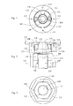
FIG. 1 is a top cross-sectional view of the present invention -
FIG. 2 is a cross sectional view of the present invention -
FIG 3 is a bottom view of the present invention -
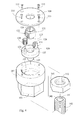
FIG 4 is a dimensional exploded view of the present invention -
Fig. 5 is a dimensional view of the polyhedral cylinder (141') replacing the inner polygonal hole (141) inFIG. 5 of the present invention -
FIG. 6 is a sectional view of the installation of polyhedral cylinder (141') inFIG. 1 to FIG. 4 of the present invention -
FIG. 7 is an operational dimensional view of the screw-on type guard of the present invention -
FIG. 8 is the cross-sectional view ofFIG 7 -
FIG. 9 is a dimensional view of the inner polygonal hole (124) replacing the polyhedral cylinder (124') inFIG. 1 to FIG. 4 -
FIG. 10 is the cross-sectional view ofFIG. 9 -
FIG. 11 is an operational view of the installation of an axial hole (125') on the sun gear cylinder (121) and the installation of an boss (126') on the planetary gear radial arm base (127) -
FIG. 12 is a functional view of the driven stud (140) being welded on the structure (200) -
FIG 13 is a functional view of the stud (140) being screwed on the screw hole of the structure (200) of the present invention -
FIG. 14 is a functional view of the present invention showing the stud (140) penetrating the structure with the other end installed with a nut -
FIG 15 is a functional view of the stud (140) of the present invention penetrating through the structure (200) with a limit stud bolt head at the other end -
FIG. 16 is a functional view of the present invention showing both ends of the stud (140) installed with nuts (101) -
- (100) :
- Cover
- (101) :
- Nut
- (102) :
- Inner ring gear
- (103) :
- Sleeve
- (111)
- Nut-driven ring body
- (115) :
- Fixed screw
- (112) :
- Inner thread
- (121) :
- Sun gear cylinder
- (122) :
- Cylindrical tooth tip
- (123) :
- Polyhedral prismatic structure
- (123') :
- Sleeve with inner polygonal hole
- (124) :
- Inner polygonal hole
- (124')
- Polyhedral cylinder
- (125) :
- Boss
- (125') :
- Axial hole
- (126) :
- Axial hole
- (126') :
- Boss
- (127) :
- Planetary gear radial arm base
- (128) :
- Jack post
- (131) :
- Planetary gear
- (140) :
- Stud
- (141) :
- Inner polygonal hole
- (141') :
- Polyhedral cylinder
- (142) :
- Thread
- (200) :
- Structure
- (300) :
- Fixed element
- The sun gear-driven screw and nut set installs the outer ring gear on the nut, and installs the planetary gear on the bolt. The screw and nut set must be installed in the planetary gear set structure one by one which entails a relatively high production cost. The present invention of a sun gear-driven magnification driving tool relies on randomly attachable and removable sun gear-driven magnification driving tools to lock, adjust, and disassemble applied mechanism with screw structure such as screw locking device, screw adjusting device, and individual screw and nut set that do not need the installation of outer ring gear and planetary gear while reducing the installation cost for over a pair of such mechanisms.
-
FIG. 1 is the top cross-sectional view of the present invention. -
FIG 2 is a cross-sectional of the present invention. -
FIG 3 is the bottom view of the present invention. -
Fig. 4 is a dimensional exploded view of the present invention. - As shown in
FIG 1 to FIG. 4 , the present invention drives the following screw and nut devices including: - - Nut (101): A structure with polygonal exterior and inner thread (112) on inner part for fastening on the thread (142) of the stud (140);
- - Stud (140): Stud (140) includes threads (142) while the stud head of the stud (140) includes concave polygonal hole (141) or it assumes the form of a polyhedral cylinder (141');
- The inner polygonal hole (141) of the aforementioned stud head of the stud (140) is optionally replaced by the polyhedral cylinder (141') as shown in the dimensional view in
FIG. 5 wherein the polyhedral cylinder (141') replaces the inner polygonal hole (141) inFIG. 1 to FIG. 4 . When the polyhedral cylinder (141') is chosen to be installed, the polyhedral prismatic structure (123) coupled with the polyhedral cylinder (141') will be transformed into a sleeve with inner polygonal hole (123') in order to fit into and drive the polyhedral cylinder (141').FIG. 6 is a cross-sectional view of the installation of the polyhedral cylinder (141') inFIG. 1 to FIG. 5 . -
FIG. 7 is the operational dimensional view of the screw-on type guard of the present invention -
FIG. 8 is the cross-sectional view ofFIG.7 - The main components of the sun gear-driven magnification driving tool includes:
- - Cover (100): A removable cap-shape locking structure to provide fixed screw (115) a means of axial lockability or by using a bottle cap-shape cover as an outer ring to screw or fasten itself on the top section of the nut-driven ring body (111). The planetary gear set is protected by means of the aforementioned cover (100). The cover (100) has a hole in the middle for inserting a tool to drive the sun gear cylinder (121) or to provide an exposed opening at the upper axial section for tools to drive the sun gear cylinder (121).
- - Nut-driven ring body (111): A ring shape structure with its upper inner ring integrated as a whole or be installed with an inner ring gear (102) in an assembly manner. The lower section of the ring-shape structure includes a sleeve (103) to couple with the exterior side of the nut (101) so that when the inner ring gear (102) is driven, nut (101) is loosen or locked by its rotating or counter-rotating motion.
- - Planetary gear (131): To provide coupling between the sun gear of the sun gear cylinder (121) and the inner ring gear (102) of the installed nut-driven ring body (111) in order to form an interactive planetary gear set function.
- The upper part of the planetary gear radial arm base (127) is installed with one or more jack posts (128) for the planetary gear (131) to effect rotary operation. Axial hole (126) is installed in planetary gear radial arm base (127) to allow the boss (125) at the lower end of the sun gear cylinder (121) to rotate in it. The lower side of the planetary gear radial arm base (127) is made into one piece or assembled to form a polyhedral prismatic structure (123) extending downwards in order to couple and move with the inner polygonal hole (141) on the top side of the stud (140) of the thread (142).
- The aforementioned installation is comprised of one or more jack post (128) and planetary gear (131);
- - Sun gear cylinder (121): The sun gear cylinder is a cylindrical structure with its integrated top section or formed into cylindrical tooth tip (122) by assembly method. The top side of the cylindrical tooth tip (122) has inner polygonal hole (124) or the inner polygonal hole (124) is replaced with polyhedral cylinder (124') in order to accept rotary drive by the operating tool. The lower end of the sun gear cylinder (121) has a boss (125) to couple with the axial hole (126) of the planetary gear radial arm base (127) for rotation. Sun gear cylinder (121) can accept drive from a separated and randomly coupling operational tool; or the operational tool can form an assembly with the sun gear cylinder (121) or be integrated as one structure.
- The above-mentioned nut-driven ring body (111), sun gear cylinder (121), planetary gear (131) and the tools for driving the sun gear cylinder (121) collectively form the sun gear-driven magnification driving tool.
- The sun gear-driven magnification driving tool, wherein the inner polygonal hole (124) of the sun gear cylinder (121) is optionally replaced by the polyhedral cylinder (124') as shown in the dimensional view in
FIG 9 wherein the polyhedral cylinder (124') replaces the inner polygonal hole (124) inFIG 1 to FIG 4 . When the polyhedral cylinder (124') is chosen to be installed, the formation will be as shown in the cross-sectional view ofFIG. 10 regarding the installation of the polyhedral cylinder (124') inFIG. 9 . - The aforementioned sun gear-driven magnification driving tool, wherein boss (125) that is installed on the sun gear cylinder (121) and the axial hole (126) that is installed in the planetary gear radial arm base (127) are also in the form of a reversed structure as shown in
FIG. 11 ; an inter-rotating couple with one as the axial hole (125'), and the other as a boss (126'). - The aforementioned sun gear-driven magnification driving tool also makes or forms as an assembly the lower side of the aforementioned planetary gear radial arm base (127) into a sleeve with inner polygonal hole (123') (as shown in
FIG. 5 ) to replace the polyhedral prismatic structure (123) in order to couple and move with the relatively made polyhedral cylinder (141') on top of the stud (140). - The aforementioned sun gear-driven magnification driving tool, wherein the operational tool is the optional screwdriver. The inner polygonal hole (141) of the stud (140) and/or the inner polygonal hole (124) of the sun gear cylinder (121) are converted into structures with slots to couple with the working end shape of the screw driver.
- The present invention of a sun gear-driven magnification driving tool relies on manpower or fluid motor or mechanical power or electric motor to drive the operational tool for driving the sun gear cylinder (121); and to further drive the nut-driven ring body (111) with the inner ring gear (102). According to the speed reduction multiples of the planetary gear set, a magnification effect is produced to drive the nut (101) to screw on the thread (142) of the stud (140) in order to make locking or loosening drive.
- Anti-vibration padding ring or gasket is optionally installed in the space between the drivable nut (101) and the stud (140) of the sun gear-driven magnification driving tool or the nut is directly screwed on the thread (142) of the stud (140). The bottom end of the stud (140) serves as:
- 1) The stud (140) is welded on the structure (200) and the nut (101) is screwed on the stud (140) to lock or release the fixed element (300), its characteristics is that the stud is facing towards the rear end of the tool, and it contains an inner polygonal hole or polyhedral;
FIG. 12 is a functional view of the present invention showing the driven stud (140) being welded on the structure (200); or - 2) The stud (140) is screwed into the screw hole of the structure (200) by means of the stud structure and the nut (101) is screwed on the stud (140) in order to lock or release the fixed element (300), its characteristics is that the stud is facing towards the rear end of the tool, and it contains an inner polygonal hole or polyhedral;
FIG. 13 is a functional view of the present invention showing the stud (140) being screwed into the screw hole of the structure (200); or - 3) The stud (140) penetrates through the structure (200) with a nut at the other end joined to the structure (200); the nut (101) serves to screw onto the stud (140) in order to lock or release the fixed element (300), its characteristics is that the stud is facing towards the rear end of the tool, and it contains an inner polygonal hole or polyhedral;
FIG 14 is a functional view of the present invention showing the stud (140) penetrating the structure with the other ) end installed with a nut; or - 4) The stud (140) penetrates through the structure (200) with a limit stud bolt head at the other end joined to the structure (200); the nut (101) serves to screw on the stud (140) in order to lock or release the fixed element (300), its characteristics is that the stud is facing towards the rear end of the tool, and it contains an inner polygonal hole or polyhedral;
FIG 15 is a functional view of the present invention showing the stud (140) penetrating through the structure (200) with a limit stud bolt head at the other end; or - 5) The stud (140) penetrates through the structure (200) and the fixed element (300), and nuts (101) are screwed on both ends of the stud (140) in order to lock or release the fixed element (300), its characteristics is that the stud is facing towards the rear end of the tool, and it contains an inner polygonal hole or polyhedral;
FIG 16 is the functional view of the present invention showing both ends of the stud (140) installed with nuts (101); - Drive operational tool employs one or more driving method of operational drive on the sun gear cylinder (121) and/or stud (140) including: 1) one directional or reverse rotary drive 2) reciprocating type one-way drive in which one driving direction produces driving effect while the other does not produce driving effect; 3) reciprocating type one-way drive in which one driving direction is chosen to produce driving effect while the other direction does not produce driving effect.
- Aside from the sun gear cylinder (121) having protruding polyhedral cylinder (124') or inner polygonal hole (124); and/or the stud (140) head having inner protruding hole (141) or protruding polyheadral cylinder (141'), the kinds of sun gear-driven magnification driving tools are many. The following are merely some of the several modes which are not to be used as restrictions. Coupling modes are formed by one or more of the following:
- 1) The sun gear cylinder (121) can randomly couple with driving tools with T-type or L-type handles;
- 2) The sun gear cylinder (121) and the T-type or L-type handle driving tool assume an integrated structure or an assembled structure;
- 3) The randomly coupling driving tools of the sun gear cylinder (121), or the assembly type or integrated type driving tools including the T-type or L-type handles possess articulating structure with foldable or universal adjusting angles;
- 4) The sun gear cylinder (121) has concave inner polygonal hole (124) to accept drive modes of relatively coupleable driving tools including pulling by pulling tools or drive from rotary drive tools;
- 5) The sun gear cylinder (121) has protruding polyhedrons to accept driving modes of relatively coupling driving tools including drive by pulling tools or drive from rotary driving tools.
- Aside from using various kinds of driving tools such as socket wrench, open wrench, closed wrench or polygonal wrench, the driving tool provided by the sun gear-driven magnification driving tools for driving the sun gear cylinder (121) and/or the stud (140) further include one or more of the following functional devices such as ; 1) functional devices with torque limit; 2) functional devices which can adjust and set the required torque limit; 3) functional device with drive torque analog or digital display; 4) functional device that display drive torque with sound or voice; 5) functional device that displays drive torque with lamps.
Claims (14)
- A sun gear-driven magnification driving tool relies on randomly attachable and removable sun gear-driven magnification driving tools to lock, adjust, and disassemble applied mechanism with screw structure such as screw locking device, screw adjusting device, and individual screw and nut set that do not need the installation of outer ring gear and planetary gear;
the main components of the sun gear-driven magnification driving tool includes:- - Cover (100): A removable cap-shape locking structure to provide fixed screw (115) a means of axial lockability or by using a bottle cap-shape cover as an outer ring to screw or fasten itself on the top section of the nut-driven ring body (111); the planetary gear set is protected by means of the aforementioned cover (100); the cover (100) has a hole in the middle for inserting a tool to drive the sun gear cylinder (121) or to provide an exposed opening at the upper axial section for tools to drive the sun gear cylinder (121);- - Nut-driven ring body (111): A ring shape structure with its upper inner ring integrated as a whole or be installed with an inner ring gear (102) in an assembly manner; the lower section of the ring-shape structure includes a sleeve (103) to couple with the exterior side of the nut (101) so that when the inner ring gear (102) is driven, nut (101) is loosen or locked by its rotating or counter-rotating motion;- - Planetary gear (131): To provide coupling between the sun gear of the sun gear cylinder (121) and the inner ring gear (102) of the installed nut-driven ring body (111) in order to form an interactive planetary gear set function;the upper part of the planetary gear radial arm base (127) is installed with one or more jack posts (128) for the planetary gear (131) to effect rotary operation; axial hole (126) is installed in planetary gear radial arm base (127) to allow the boss (125) at the lower end of the sun gear cylinder (121) to rotate in it; the lower side of the planetary gear radial arm base (127) is made into one piece or assembled to form a polyhedral prismatic structure (123) extending downwards in order to couple and move with the inner polygonal hole (141) on the top side of the stud (140) of the thread (142);
the aforementioned installation is comprised of one or more jack post (128) and planetary gear (131);- - Sun gear cylinder (121): The sun gear cylinder is a cylindrical structure with its integrated top section or formed into cylindrical tooth tip (122) by assembly method; the top side of the cylindrical tooth tip (122) has inner polygonal hole (124) or the inner polygonal hole (124) is replaced with polyhedral cylinder (124') in order to accept rotary drive by the operating tool; the lower end of the sun gear cylinder (121) has a boss (125) to couple with the axial hole (126) of the planetary gear radial arm base (127) for rotation. Sun gear cylinder (121) can accept drive from a separated and randomly coupling operational tool;the above-mentioned nut-driven ring body (111), sun gear cylinder (121), planetary gear (131) and the tools for driving the sun gear cylinder (121) collectively form the sun gear-driven magnification driving tool. - A sun gear-driven magnification driving tool as claimed in claim 1, wherein the operational tool can form an assembly with the sun gear cylinder (121) or be integrated as one structure.
- A sun gear-driven magnification driving tool as claimed in claim 1 or 2, wherein the inner polygonal hole (124) of the sun gear cylinder (121) is optionally replaced by the polyhedral cylinder (124').
- A sun gear-driven magnification driving tool as claimed in any one of claims I to 3, wherein the boss (125) that is installed on the sun gear cylinder (121) and the axial hole (126) that is installed in the planetary gear radial arm base (127) are also in the form of a reversed structure as such is to conduct an inter-rotating couple with one as the axial hole (125'), and the other as a boss (126').
- A sun gear-driven magnification driving tool as claimed in any one of claims I to 4 also makes or forms as an assembly the lower side of the aforementioned planetary gear radial arm base (127) into a sleeve with inner polygonal hole (123') to replace the polyhedral prismatic structure (123) in order to couple and move with the relatively made polyhedral cylinder (141') on top of the stud (140).
- A sun gear-driven magnification driving tool as claimed in any one of the preceding claims, wherein the operational tool is the optional screwdriver; the inner polygonal hole (141) of the stud (140) and/or the inner polygonal hole (124) of the sun gear cylinder (121) are converted into structures with slots to couple with the working end shape of the screw driver.
- A sun gear-driven magnification driving tool as claimed in any one of the preceding claims relies on manpower or fluid motor or mechanical power or electric motor to drive the operational tool for driving the sun gear cylinder (121); and to further drive the nut-driven ring body (111) with the inner ring gear (102); according to the speed reduction multiples of the planetary gear set, a magnification effect is produced to drive the nut (101) to screw on the thread (142) of the stud (140) in order to make locking or loosening drive.
- A stud structure driven by the sun gear-driven magnification driving tool of any one of the preceding claims, wherein the bottom end of the stud (140) is welded on the structure (200) and the nut (101) is screwed on the stud (140) to lock or release the fixed element (300), its characteristics is that the stud is facing towards the rear end of the tool, and it contains an inner polygonal hole or polyhedral.
- A stud structure driven by the sun gear-driven magnification driving tool of any one of claims 1 to 7, wherein the bottom end of the stud (140) is screwed into the screw hole of the structure (200) by means of the stud structure and the nut (101) is screwed on the stud (140) in order to lock or release the fixed element (300), its characteristics is that the stud is facing towards the rear end of the tool, and it contains an inner polygonal hole or polyhedral.
- A stud structure driven by the sun gear-driven magnification driving tool of any one of claims 1 to 7, wherein the bottom end of the stud (140) penetrates through the structure (200) with a nut at the other end joined to the structure (200); the nut (101) serves to screw onto the stud (140) in order to lock or release the fixed element (300), its characteristics is that the stud is facing towards the rear end of the tool, and it contains an inner polygonal hole or polyhedral.
- A stud structure driven by the sun gear-driven magnification driving tool of any one of claims 1 to 7, wherein the bottom end of the stud (140) penetrates through the structure (200) with a limit stud bolt head at the other end joined to the structure (200); the nut (101) serves to screw on the stud (140) in order to lock or release the fixed element (300), its characteristics is that the stud is facing towards the rear end of the tool, and it contains an inner polygonal hole or polyhedral.
- A stud structure driven by the sun gear-driven magnification driving tool of any one of claims 1 to 7, wherein the bottom end of the stud (140) penetrates through the structure (200) and the fixed element (300), and nuts (101) are screwed on both ends of the stud (140) in order to lock or release the fixed element (300), its characteristics is that the stud is facing towards the rear end of the tool, and it contains an inner polygonal hole or polyhedral.
- A sun gear-driven magnification driving tool as claimed in any one of claims 1 to 7, wherein the tool can drive the following screw and nut devices including:- - Nut (101): A structure with polygonal exterior and inner thread (112) on inner part for fastening on the thread (142) of the stud (140);- - Stud (140): Stud (140) includes threads (142) while the stud head of the stud (140) includes concave polygonal hole (141) or it assumes the form of a polyhedral cylinder (141').
- A sun gear-driven magnification driving tool as claimed in claim 13, wherein the inner polygonal hole (141) of the stud head of the stud (140) is optionally replaced by the polyhedral cylinder (141'); when the polyhedral cylinder (141') is chosen to be installed, the polyhedral prismatic structure (123) coupled with the polyhedral cylinder (141') will be transformed into a sleeve with inner polygonal hole (123') in order to fit into and drive the polyhedral cylinder (141').
Applications Claiming Priority (1)
| Application Number | Priority Date | Filing Date | Title |
|---|---|---|---|
| US12/461,524 US8225698B2 (en) | 2009-08-14 | 2009-08-14 | Sun gear-driven magnification driving tool |
Publications (2)
| Publication Number | Publication Date |
|---|---|
| EP2283975A1 true EP2283975A1 (en) | 2011-02-16 |
| EP2283975B1 EP2283975B1 (en) | 2012-05-09 |
Family
ID=42732032
Family Applications (1)
| Application Number | Title | Priority Date | Filing Date |
|---|---|---|---|
| EP10171314A Not-in-force EP2283975B1 (en) | 2009-08-14 | 2010-07-29 | Sun gear-driven torque multiplying tool |
Country Status (9)
| Country | Link |
|---|---|
| US (1) | US8225698B2 (en) |
| EP (1) | EP2283975B1 (en) |
| JP (1) | JP5710908B2 (en) |
| KR (1) | KR20110017836A (en) |
| AT (1) | ATE556816T1 (en) |
| DE (1) | DE202010011356U1 (en) |
| DK (1) | DK2283975T3 (en) |
| ES (1) | ES2388624T3 (en) |
| TW (1) | TWM383058U (en) |
Cited By (1)
| Publication number | Priority date | Publication date | Assignee | Title |
|---|---|---|---|---|
| CN104084923A (en) * | 2014-07-08 | 2014-10-08 | 河北科技大学 | Sleeve electric wrench for rebar threaded connection |
Families Citing this family (19)
| Publication number | Priority date | Publication date | Assignee | Title |
|---|---|---|---|---|
| TW201223715A (en) * | 2010-12-03 | 2012-06-16 | Matatakitoyo Tool Co Ltd | A hand tool torque indicating device |
| EP2688713B1 (en) * | 2011-03-22 | 2016-07-06 | Chad M. Larson | Torque-angle structural fastening system |
| US8968001B2 (en) | 2011-03-22 | 2015-03-03 | Arthur Thomas Forrest | Forrest sponge aided sinus membrane lift technique |
| EP2654122B1 (en) | 2011-09-02 | 2018-04-04 | Huawei Technologies Co., Ltd. | Active antenna system |
| US9138876B2 (en) * | 2012-07-20 | 2015-09-22 | Robert F. Cullison | Torque multiplier and method of use |
| US9796075B2 (en) | 2014-02-14 | 2017-10-24 | Apex Brands, Inc. | Fixturing device and method of use |
| TWM520962U (en) * | 2016-01-11 | 2016-05-01 | 寶達精業股份有限公司 | Double force device |
| CN109789539B (en) * | 2016-09-23 | 2021-10-26 | 阿特拉斯·科普柯工业技术公司 | Hydraulic screw tensioning device |
| US10427276B2 (en) | 2017-03-24 | 2019-10-01 | Tym Labs L.L.C. | Torque multiplier module |
| US10738817B2 (en) | 2017-04-11 | 2020-08-11 | Turnasure Llc | Self-indicating direct tension indicator |
| US11267110B2 (en) | 2017-08-02 | 2022-03-08 | Tym Labs L.L.C. | Zero distance tool |
| CN107838666A (en) * | 2017-11-06 | 2018-03-27 | 佛山科学技术学院 | A kind of secondary gap adjusting nut handler of portable sliding screw |
| DE102018207462A1 (en) * | 2018-05-15 | 2019-11-21 | Hyundai Motor Company | connection system |
| AU2021265587A1 (en) * | 2020-05-01 | 2023-01-19 | Mohlalefi (Pty) Ltd | Nut arrangement, rock bolt and driver apparatus |
| US11274765B2 (en) | 2020-06-08 | 2022-03-15 | Caterpillar Inc. | Valve cap adapter and arrangement and method of removing a valve cap |
| USD992690S1 (en) | 2020-06-08 | 2023-07-18 | Caterpillar Inc. | Valve cap adapter |
| CN115835937A (en) * | 2020-07-01 | 2023-03-21 | 朗姆研究公司 | Tool and method for ceiling-lamp type spray head installation |
| US12408585B2 (en) | 2021-04-23 | 2025-09-09 | Techtronic Cordless Gp | Force amplified fastener for power tool implements |
| CN113997243A (en) * | 2021-12-10 | 2022-02-01 | 天威保变(合肥)变压器有限公司 | Adjustable winding former flange disc screw rod mounting tool of vertical winding machine tool |
Citations (4)
| Publication number | Priority date | Publication date | Assignee | Title |
|---|---|---|---|---|
| US2630731A (en) * | 1950-07-29 | 1953-03-10 | Imboden Winston | Gear-operated dual socket wrench |
| US3324747A (en) * | 1965-04-23 | 1967-06-13 | Sweeney Mfg Co B K | Bolt tightening tool |
| US5123308A (en) * | 1990-10-05 | 1992-06-23 | Consulier Engineering, Inc. | Torque multiplying lug nut wrench |
| DE102005051131A1 (en) * | 2004-11-10 | 2006-05-11 | Anneliese Norra | Hand tool for tightening/loosening screw thread of e.g. screw, for weak person, has planet wheels arranged between gear wheel and gear ring, and transferring rotary motion of hand grip with reduced speed onto output shaft |
Family Cites Families (23)
| Publication number | Priority date | Publication date | Assignee | Title |
|---|---|---|---|---|
| US1343667A (en) * | 1919-07-12 | 1920-06-15 | Evensen Carl | Bolting-up device |
| US2537382A (en) * | 1949-11-18 | 1951-01-09 | Veelox Rivet & Tool Corp | Gear operated, bolt-holding wrench |
| US2955496A (en) * | 1958-12-15 | 1960-10-11 | Torre Kathryn S La | Power-operated, bolt-holding wrench |
| US3472083A (en) * | 1967-10-25 | 1969-10-14 | Lawrence S Schnepel | Torque wrench |
| US3916734A (en) * | 1974-08-21 | 1975-11-04 | Anis S Sawan | Tool for use in removing automobile shock absorbers |
| US3942398A (en) * | 1974-10-10 | 1976-03-09 | Nasa | Zero torque gear head wrench |
| US3979965A (en) * | 1975-06-11 | 1976-09-14 | Consolidated Devices, Inc. | Torque multiplier tool |
| US4403529A (en) * | 1981-08-19 | 1983-09-13 | Maeda Metal Industries Ltd. | Device for fastening bolts |
| JPS60186166U (en) * | 1984-05-23 | 1985-12-10 | トヨタ自動車株式会社 | Socket trench for double nuts |
| JPS62104871U (en) * | 1985-12-20 | 1987-07-04 | ||
| JPS62134670U (en) * | 1986-02-20 | 1987-08-25 | ||
| US5238461A (en) * | 1991-02-11 | 1993-08-24 | Gotman Alexander S | Reactionlless differential rotary driver having optimized output torques |
| JPH0731277U (en) * | 1993-11-11 | 1995-06-13 | 前田金属工業株式会社 | Nut tightening machine |
| JPH0839448A (en) * | 1994-07-26 | 1996-02-13 | Maeda Kinzoku Kogyo Kk | Bolt tightening machine |
| JP2756245B2 (en) * | 1996-05-30 | 1998-05-25 | 前田金属工業株式会社 | Bolt and nut tightening machine |
| JP3229930B2 (en) * | 1997-08-20 | 2001-11-19 | 前田金属工業株式会社 | Bolt tightening machine |
| US6058810A (en) * | 1998-11-07 | 2000-05-09 | Junkers; John K. | Power tool for and a method of moving an element relative to an object |
| US6487940B2 (en) * | 2001-01-23 | 2002-12-03 | Associated Toolmakers Incorporated | Nut driver |
| US7225707B2 (en) * | 2005-09-14 | 2007-06-05 | Brian Knopp | Torque wrench with quick-release gear set |
| ES2334081B2 (en) * | 2006-04-28 | 2011-12-12 | Unex Corporation | MOTORIZED TORQUE INTENSIFIER. |
| US7794355B2 (en) * | 2007-05-15 | 2010-09-14 | Snap-On Incorporated | Planetary gear set centering ring |
| US7748296B2 (en) * | 2008-07-24 | 2010-07-06 | Gong Fong Enterprise Co., Ltd. | Ratchet screwdriver with an accelerating structure |
| US7987745B2 (en) * | 2009-01-16 | 2011-08-02 | Gauthier Biomedical, Inc. | Variable gear ratio ratchet |
-
2009
- 2009-08-14 US US12/461,524 patent/US8225698B2/en not_active Expired - Fee Related
- 2009-08-18 TW TW098215180U patent/TWM383058U/en unknown
-
2010
- 2010-07-29 AT AT10171314T patent/ATE556816T1/en active
- 2010-07-29 ES ES10171314T patent/ES2388624T3/en active Active
- 2010-07-29 EP EP10171314A patent/EP2283975B1/en not_active Not-in-force
- 2010-07-29 DK DK10171314.7T patent/DK2283975T3/en active
- 2010-08-10 JP JP2010179828A patent/JP5710908B2/en not_active Expired - Fee Related
- 2010-08-13 DE DE202010011356U patent/DE202010011356U1/en not_active Expired - Lifetime
- 2010-08-13 KR KR1020100078300A patent/KR20110017836A/en not_active Withdrawn
Patent Citations (4)
| Publication number | Priority date | Publication date | Assignee | Title |
|---|---|---|---|---|
| US2630731A (en) * | 1950-07-29 | 1953-03-10 | Imboden Winston | Gear-operated dual socket wrench |
| US3324747A (en) * | 1965-04-23 | 1967-06-13 | Sweeney Mfg Co B K | Bolt tightening tool |
| US5123308A (en) * | 1990-10-05 | 1992-06-23 | Consulier Engineering, Inc. | Torque multiplying lug nut wrench |
| DE102005051131A1 (en) * | 2004-11-10 | 2006-05-11 | Anneliese Norra | Hand tool for tightening/loosening screw thread of e.g. screw, for weak person, has planet wheels arranged between gear wheel and gear ring, and transferring rotary motion of hand grip with reduced speed onto output shaft |
Cited By (2)
| Publication number | Priority date | Publication date | Assignee | Title |
|---|---|---|---|---|
| CN104084923A (en) * | 2014-07-08 | 2014-10-08 | 河北科技大学 | Sleeve electric wrench for rebar threaded connection |
| CN104084923B (en) * | 2014-07-08 | 2015-11-11 | 河北科技大学 | A kind of sleeve electric wrench connected for screw thread steel |
Also Published As
| Publication number | Publication date |
|---|---|
| US8225698B2 (en) | 2012-07-24 |
| DK2283975T3 (en) | 2012-08-27 |
| DE202010011356U1 (en) | 2010-11-18 |
| EP2283975B1 (en) | 2012-05-09 |
| US20110036206A1 (en) | 2011-02-17 |
| JP5710908B2 (en) | 2015-04-30 |
| TWM383058U (en) | 2010-06-21 |
| KR20110017836A (en) | 2011-02-22 |
| JP2011036996A (en) | 2011-02-24 |
| ATE556816T1 (en) | 2012-05-15 |
| ES2388624T3 (en) | 2012-10-17 |
Similar Documents
| Publication | Publication Date | Title |
|---|---|---|
| EP2283975B1 (en) | Sun gear-driven torque multiplying tool | |
| US8220365B2 (en) | Planetary gear-driven magnification driving tool | |
| EP2284406B1 (en) | Sun gear coaxially driven screw and nut structure | |
| US5709136A (en) | Power driven tools | |
| TW201829134A (en) | Electric socket wrench allowing a shaft hole to receive a corresponding bolt to insert therein | |
| CN101062555A (en) | Power-driven torque intensifier | |
| CN101994747B (en) | Sun gear coaxial drive screw nut structure and its driven stud structure | |
| JP6145184B1 (en) | Double head type electric tool | |
| TWI449604B (en) | Sun gear coaxially driven screw and nut structure | |
| TWI451946B (en) | Sun gear-driven magnification driving tool | |
| CN210476775U (en) | Multi-bolt synchronous fastening tool | |
| CN114434375B (en) | Screw loading and unloading assistor | |
| CN1853852B (en) | Power tool and method for moving a component relative to an object | |
| JP2006007389A (en) | Impact tools | |
| CN101992434B (en) | Sun gear-driven double force driving tool and its driven stud structure | |
| KR200396430Y1 (en) | Ratchet Wrench | |
| CN214643127U (en) | Adjusting tool for stroke part sleeve of valve electric device | |
| US20260124721A1 (en) | Power ratchet wrench head | |
| CN116276813A (en) | A fastening tool for anchor bolts | |
| KR20100010392U (en) | Box socet | |
| JP2000052265A (en) | Socket wrench adapter |
Legal Events
| Date | Code | Title | Description |
|---|---|---|---|
| PUAI | Public reference made under article 153(3) epc to a published international application that has entered the european phase |
Free format text: ORIGINAL CODE: 0009012 |
|
| AK | Designated contracting states |
Kind code of ref document: A1 Designated state(s): AL AT BE BG CH CY CZ DE DK EE ES FI FR GB GR HR HU IE IS IT LI LT LU LV MC MK MT NL NO PL PT RO SE SI SK SM TR |
|
| AX | Request for extension of the european patent |
Extension state: BA ME RS |
|
| 17P | Request for examination filed |
Effective date: 20110816 |
|
| GRAP | Despatch of communication of intention to grant a patent |
Free format text: ORIGINAL CODE: EPIDOSNIGR1 |
|
| RIC1 | Information provided on ipc code assigned before grant |
Ipc: B25B 13/48 20060101ALI20110907BHEP Ipc: B25B 17/02 20060101AFI20110907BHEP |
|
| GRAS | Grant fee paid |
Free format text: ORIGINAL CODE: EPIDOSNIGR3 |
|
| GRAA | (expected) grant |
Free format text: ORIGINAL CODE: 0009210 |
|
| RIN1 | Information on inventor provided before grant (corrected) |
Inventor name: YANG, TAI-HER |
|
| AK | Designated contracting states |
Kind code of ref document: B1 Designated state(s): AL AT BE BG CH CY CZ DE DK EE ES FI FR GB GR HR HU IE IS IT LI LT LU LV MC MK MT NL NO PL PT RO SE SI SK SM TR |
|
| REG | Reference to a national code |
Ref country code: GB Ref legal event code: FG4D |
|
| REG | Reference to a national code |
Ref country code: AT Ref legal event code: REF Ref document number: 556816 Country of ref document: AT Kind code of ref document: T Effective date: 20120515 Ref country code: CH Ref legal event code: EP |
|
| REG | Reference to a national code |
Ref country code: IE Ref legal event code: FG4D |
|
| REG | Reference to a national code |
Ref country code: DE Ref legal event code: R096 Ref document number: 602010001415 Country of ref document: DE Effective date: 20120705 |
|
| REG | Reference to a national code |
Ref country code: DK Ref legal event code: T3 |
|
| REG | Reference to a national code |
Ref country code: SE Ref legal event code: TRGR |
|
| REG | Reference to a national code |
Ref country code: NL Ref legal event code: VDEP Effective date: 20120509 |
|
| REG | Reference to a national code |
Ref country code: ES Ref legal event code: FG2A Ref document number: 2388624 Country of ref document: ES Kind code of ref document: T3 Effective date: 20121017 |
|
| REG | Reference to a national code |
Ref country code: LT Ref legal event code: MG4D Effective date: 20120509 |
|
| PG25 | Lapsed in a contracting state [announced via postgrant information from national office to epo] |
Ref country code: NO Free format text: LAPSE BECAUSE OF FAILURE TO SUBMIT A TRANSLATION OF THE DESCRIPTION OR TO PAY THE FEE WITHIN THE PRESCRIBED TIME-LIMIT Effective date: 20120809 Ref country code: IS Free format text: LAPSE BECAUSE OF FAILURE TO SUBMIT A TRANSLATION OF THE DESCRIPTION OR TO PAY THE FEE WITHIN THE PRESCRIBED TIME-LIMIT Effective date: 20120909 Ref country code: FI Free format text: LAPSE BECAUSE OF FAILURE TO SUBMIT A TRANSLATION OF THE DESCRIPTION OR TO PAY THE FEE WITHIN THE PRESCRIBED TIME-LIMIT Effective date: 20120509 Ref country code: PL Free format text: LAPSE BECAUSE OF FAILURE TO SUBMIT A TRANSLATION OF THE DESCRIPTION OR TO PAY THE FEE WITHIN THE PRESCRIBED TIME-LIMIT Effective date: 20120509 Ref country code: LT Free format text: LAPSE BECAUSE OF FAILURE TO SUBMIT A TRANSLATION OF THE DESCRIPTION OR TO PAY THE FEE WITHIN THE PRESCRIBED TIME-LIMIT Effective date: 20120509 Ref country code: CY Free format text: LAPSE BECAUSE OF FAILURE TO SUBMIT A TRANSLATION OF THE DESCRIPTION OR TO PAY THE FEE WITHIN THE PRESCRIBED TIME-LIMIT Effective date: 20120509 |
|
| REG | Reference to a national code |
Ref country code: AT Ref legal event code: MK05 Ref document number: 556816 Country of ref document: AT Kind code of ref document: T Effective date: 20120509 |
|
| PG25 | Lapsed in a contracting state [announced via postgrant information from national office to epo] |
Ref country code: HR Free format text: LAPSE BECAUSE OF FAILURE TO SUBMIT A TRANSLATION OF THE DESCRIPTION OR TO PAY THE FEE WITHIN THE PRESCRIBED TIME-LIMIT Effective date: 20120509 Ref country code: LV Free format text: LAPSE BECAUSE OF FAILURE TO SUBMIT A TRANSLATION OF THE DESCRIPTION OR TO PAY THE FEE WITHIN THE PRESCRIBED TIME-LIMIT Effective date: 20120509 Ref country code: PT Free format text: LAPSE BECAUSE OF FAILURE TO SUBMIT A TRANSLATION OF THE DESCRIPTION OR TO PAY THE FEE WITHIN THE PRESCRIBED TIME-LIMIT Effective date: 20120910 Ref country code: SI Free format text: LAPSE BECAUSE OF FAILURE TO SUBMIT A TRANSLATION OF THE DESCRIPTION OR TO PAY THE FEE WITHIN THE PRESCRIBED TIME-LIMIT Effective date: 20120509 Ref country code: GR Free format text: LAPSE BECAUSE OF FAILURE TO SUBMIT A TRANSLATION OF THE DESCRIPTION OR TO PAY THE FEE WITHIN THE PRESCRIBED TIME-LIMIT Effective date: 20120810 |
|
| PG25 | Lapsed in a contracting state [announced via postgrant information from national office to epo] |
Ref country code: BE Free format text: LAPSE BECAUSE OF FAILURE TO SUBMIT A TRANSLATION OF THE DESCRIPTION OR TO PAY THE FEE WITHIN THE PRESCRIBED TIME-LIMIT Effective date: 20120509 |
|
| PG25 | Lapsed in a contracting state [announced via postgrant information from national office to epo] |
Ref country code: AT Free format text: LAPSE BECAUSE OF FAILURE TO SUBMIT A TRANSLATION OF THE DESCRIPTION OR TO PAY THE FEE WITHIN THE PRESCRIBED TIME-LIMIT Effective date: 20120509 Ref country code: CZ Free format text: LAPSE BECAUSE OF FAILURE TO SUBMIT A TRANSLATION OF THE DESCRIPTION OR TO PAY THE FEE WITHIN THE PRESCRIBED TIME-LIMIT Effective date: 20120509 Ref country code: NL Free format text: LAPSE BECAUSE OF FAILURE TO SUBMIT A TRANSLATION OF THE DESCRIPTION OR TO PAY THE FEE WITHIN THE PRESCRIBED TIME-LIMIT Effective date: 20120509 Ref country code: RO Free format text: LAPSE BECAUSE OF FAILURE TO SUBMIT A TRANSLATION OF THE DESCRIPTION OR TO PAY THE FEE WITHIN THE PRESCRIBED TIME-LIMIT Effective date: 20120509 Ref country code: EE Free format text: LAPSE BECAUSE OF FAILURE TO SUBMIT A TRANSLATION OF THE DESCRIPTION OR TO PAY THE FEE WITHIN THE PRESCRIBED TIME-LIMIT Effective date: 20120509 Ref country code: SK Free format text: LAPSE BECAUSE OF FAILURE TO SUBMIT A TRANSLATION OF THE DESCRIPTION OR TO PAY THE FEE WITHIN THE PRESCRIBED TIME-LIMIT Effective date: 20120509 |
|
| PG25 | Lapsed in a contracting state [announced via postgrant information from national office to epo] |
Ref country code: MC Free format text: LAPSE BECAUSE OF NON-PAYMENT OF DUE FEES Effective date: 20120731 Ref country code: MK Free format text: LAPSE BECAUSE OF FAILURE TO SUBMIT A TRANSLATION OF THE DESCRIPTION OR TO PAY THE FEE WITHIN THE PRESCRIBED TIME-LIMIT Effective date: 20120509 |
|
| REG | Reference to a national code |
Ref country code: SE Ref legal event code: EUG |
|
| PLBE | No opposition filed within time limit |
Free format text: ORIGINAL CODE: 0009261 |
|
| STAA | Information on the status of an ep patent application or granted ep patent |
Free format text: STATUS: NO OPPOSITION FILED WITHIN TIME LIMIT |
|
| 26N | No opposition filed |
Effective date: 20130212 |
|
| PG25 | Lapsed in a contracting state [announced via postgrant information from national office to epo] |
Ref country code: SE Free format text: LAPSE BECAUSE OF NON-PAYMENT OF DUE FEES Effective date: 20120730 |
|
| REG | Reference to a national code |
Ref country code: IE Ref legal event code: MM4A |
|
| REG | Reference to a national code |
Ref country code: DE Ref legal event code: R097 Ref document number: 602010001415 Country of ref document: DE Effective date: 20130212 |
|
| PG25 | Lapsed in a contracting state [announced via postgrant information from national office to epo] |
Ref country code: IE Free format text: LAPSE BECAUSE OF NON-PAYMENT OF DUE FEES Effective date: 20120729 Ref country code: BG Free format text: LAPSE BECAUSE OF FAILURE TO SUBMIT A TRANSLATION OF THE DESCRIPTION OR TO PAY THE FEE WITHIN THE PRESCRIBED TIME-LIMIT Effective date: 20120809 Ref country code: MT Free format text: LAPSE BECAUSE OF FAILURE TO SUBMIT A TRANSLATION OF THE DESCRIPTION OR TO PAY THE FEE WITHIN THE PRESCRIBED TIME-LIMIT Effective date: 20120509 |
|
| REG | Reference to a national code |
Ref country code: SE Ref legal event code: RINS Effective date: 20130723 |
|
| PG25 | Lapsed in a contracting state [announced via postgrant information from national office to epo] |
Ref country code: AL Free format text: LAPSE BECAUSE OF FAILURE TO SUBMIT A TRANSLATION OF THE DESCRIPTION OR TO PAY THE FEE WITHIN THE PRESCRIBED TIME-LIMIT Effective date: 20120509 |
|
| PGRI | Patent reinstated in contracting state [announced from national office to epo] |
Ref country code: SE Effective date: 20130723 |
|
| REG | Reference to a national code |
Ref country code: DK Ref legal event code: EBP Effective date: 20130731 |
|
| PG25 | Lapsed in a contracting state [announced via postgrant information from national office to epo] |
Ref country code: TR Free format text: LAPSE BECAUSE OF FAILURE TO SUBMIT A TRANSLATION OF THE DESCRIPTION OR TO PAY THE FEE WITHIN THE PRESCRIBED TIME-LIMIT Effective date: 20120509 |
|
| PG25 | Lapsed in a contracting state [announced via postgrant information from national office to epo] |
Ref country code: SM Free format text: LAPSE BECAUSE OF FAILURE TO SUBMIT A TRANSLATION OF THE DESCRIPTION OR TO PAY THE FEE WITHIN THE PRESCRIBED TIME-LIMIT Effective date: 20120509 Ref country code: LU Free format text: LAPSE BECAUSE OF NON-PAYMENT OF DUE FEES Effective date: 20120729 |
|
| PG25 | Lapsed in a contracting state [announced via postgrant information from national office to epo] |
Ref country code: HU Free format text: LAPSE BECAUSE OF FAILURE TO SUBMIT A TRANSLATION OF THE DESCRIPTION OR TO PAY THE FEE WITHIN THE PRESCRIBED TIME-LIMIT Effective date: 20100729 |
|
| PG25 | Lapsed in a contracting state [announced via postgrant information from national office to epo] |
Ref country code: DK Free format text: LAPSE BECAUSE OF NON-PAYMENT OF DUE FEES Effective date: 20130731 |
|
| REG | Reference to a national code |
Ref country code: CH Ref legal event code: PL |
|
| PG25 | Lapsed in a contracting state [announced via postgrant information from national office to epo] |
Ref country code: LI Free format text: LAPSE BECAUSE OF NON-PAYMENT OF DUE FEES Effective date: 20140731 Ref country code: CH Free format text: LAPSE BECAUSE OF NON-PAYMENT OF DUE FEES Effective date: 20140731 |
|
| REG | Reference to a national code |
Ref country code: FR Ref legal event code: PLFP Year of fee payment: 7 |
|
| REG | Reference to a national code |
Ref country code: FR Ref legal event code: PLFP Year of fee payment: 8 |
|
| PGFP | Annual fee paid to national office [announced via postgrant information from national office to epo] |
Ref country code: IT Payment date: 20170731 Year of fee payment: 8 Ref country code: ES Payment date: 20170825 Year of fee payment: 8 |
|
| REG | Reference to a national code |
Ref country code: FR Ref legal event code: PLFP Year of fee payment: 9 |
|
| PG25 | Lapsed in a contracting state [announced via postgrant information from national office to epo] |
Ref country code: IT Free format text: LAPSE BECAUSE OF NON-PAYMENT OF DUE FEES Effective date: 20180729 |
|
| REG | Reference to a national code |
Ref country code: ES Ref legal event code: FD2A Effective date: 20190917 |
|
| PG25 | Lapsed in a contracting state [announced via postgrant information from national office to epo] |
Ref country code: ES Free format text: LAPSE BECAUSE OF NON-PAYMENT OF DUE FEES Effective date: 20180730 |
|
| REG | Reference to a national code |
Ref country code: DE Ref legal event code: R082 Ref document number: 602010001415 Country of ref document: DE Representative=s name: MEISSNER BOLTE PATENTANWAELTE RECHTSANWAELTE P, DE |
|
| PGFP | Annual fee paid to national office [announced via postgrant information from national office to epo] |
Ref country code: GB Payment date: 20230731 Year of fee payment: 14 |
|
| PGFP | Annual fee paid to national office [announced via postgrant information from national office to epo] |
Ref country code: SE Payment date: 20230731 Year of fee payment: 14 Ref country code: FR Payment date: 20230731 Year of fee payment: 14 Ref country code: DE Payment date: 20230821 Year of fee payment: 14 |
|
| REG | Reference to a national code |
Ref country code: DE Ref legal event code: R119 Ref document number: 602010001415 Country of ref document: DE |
|
| REG | Reference to a national code |
Ref country code: SE Ref legal event code: EUG |
|
| GBPC | Gb: european patent ceased through non-payment of renewal fee |
Effective date: 20240729 |
|
| PG25 | Lapsed in a contracting state [announced via postgrant information from national office to epo] |
Ref country code: DE Free format text: LAPSE BECAUSE OF NON-PAYMENT OF DUE FEES Effective date: 20250201 |
|
| PG25 | Lapsed in a contracting state [announced via postgrant information from national office to epo] |
Ref country code: FR Free format text: LAPSE BECAUSE OF NON-PAYMENT OF DUE FEES Effective date: 20240731 |
|
| PG25 | Lapsed in a contracting state [announced via postgrant information from national office to epo] |
Ref country code: GB Free format text: LAPSE BECAUSE OF NON-PAYMENT OF DUE FEES Effective date: 20240729 |
|
| PG25 | Lapsed in a contracting state [announced via postgrant information from national office to epo] |
Ref country code: SE Free format text: LAPSE BECAUSE OF NON-PAYMENT OF DUE FEES Effective date: 20240730 |