EP2283612B1 - Synchronizing device error information among nodes - Google Patents
Synchronizing device error information among nodes Download PDFInfo
- Publication number
- EP2283612B1 EP2283612B1 EP09757448A EP09757448A EP2283612B1 EP 2283612 B1 EP2283612 B1 EP 2283612B1 EP 09757448 A EP09757448 A EP 09757448A EP 09757448 A EP09757448 A EP 09757448A EP 2283612 B1 EP2283612 B1 EP 2283612B1
- Authority
- EP
- European Patent Office
- Prior art keywords
- node
- error counter
- error
- message
- response
- Prior art date
- Legal status (The legal status is an assumption and is not a legal conclusion. Google has not performed a legal analysis and makes no representation as to the accuracy of the status listed.)
- Active
Links
Images





Classifications
-
- H—ELECTRICITY
- H04—ELECTRIC COMMUNICATION TECHNIQUE
- H04L—TRANSMISSION OF DIGITAL INFORMATION, e.g. TELEGRAPHIC COMMUNICATION
- H04L41/00—Arrangements for maintenance, administration or management of data switching networks, e.g. of packet switching networks
- H04L41/06—Management of faults, events, alarms or notifications
- H04L41/0654—Management of faults, events, alarms or notifications using network fault recovery
-
- H—ELECTRICITY
- H04—ELECTRIC COMMUNICATION TECHNIQUE
- H04L—TRANSMISSION OF DIGITAL INFORMATION, e.g. TELEGRAPHIC COMMUNICATION
- H04L41/00—Arrangements for maintenance, administration or management of data switching networks, e.g. of packet switching networks
- H04L41/06—Management of faults, events, alarms or notifications
- H04L41/0677—Localisation of faults
Definitions
- the present invention relates to a method, system, and computer program for synchronizing device error information among nodes.
- Host systems in a storage network may communicate with a storage controller through multiple paths.
- the storage controller may be comprised of separate storage clusters or nodes, where each storage cluster is capable of accessing the storage and provide redundancy to access the storage.
- Hosts may access the attached storage through either cluster. If a storage cluster fails, then the host may failover to using the other storage cluster to access the storage.
- each storage node or cluster In redundant storage controller environments, it is common for each storage node or cluster to establish ownership of certain external resources, such as network and Input/Output device adaptors. If a node in the system fails, other nodes in the system can take ownership of the resources that were owned by the failing node. If an external resource in the system starts reporting errors, the owning node will begin thresholding these errors and taking appropriate system recovery actions based on the number of detected errors. If, during this process, the owning node fails, another available node takes ownership of the external resource, but may have no knowledge of the previous errors that were recorded by the failing node. This causes the new owning node to treat the next error on the external resource as if it were the first error.
- external resources such as network and Input/Output device adaptors.
- the new owning node will go through the same actions as the previous node, which could result in the new owning node failing in the same way. If other nodes in the system continue to take ownership of the resource, it could result in all nodes failing, causing the customer to lose access to data. Restarting the recovery operation from a zero error count may cause the overall system recovery (taken by the previous owning node and the new owning node) to take long enough such that the host system times out and the customer loses access to data.
- the Document US 7092768 discloses a system for controlling a plurality of (multimedia) devices which keep each other and the controller updated about the device status in order to coordinate the various actions of the multimedia devices.
- Document WO9620547 Provides a process for automatic event report realignment of state information transferred from a managed subsystem to one or more managers by an event report technique. In accordance with this process the events generated by changes in the state variables are written in a memory of the events which is managed as a circular queue by means of pointers.
- a first node performs an action with respect to a first node error counter for a device in communication with the first node and a second node.
- the first node transmits a message to the second node indicating the device and the action performed with respect to the first node error counter for the device.
- the second node performs the action indicated in the message with respect to a second node error counter for the device indicated in the message, wherein the second node error counter corresponds to the first node error counter for the device.
- the first node detects an error at the device
- the first node performs the action by incrementing the first node error counter for the device in response to detecting the error.
- the action indicated in the message comprises an increment action.
- the second node performs the increment action by incrementing the second node error counter for the device at the second node.
- the action indicated in the message comprises an open action.
- the second node performs the open action by creating the second node error counter for the device in response to the message.
- the action indicated in the message comprises an expire action.
- the second node performs the expire action by expiring the second error counter for the device in response to the message.
- the first node initiates an error recovery operation in response to the error counter value reaching an error threshold.
- the first node operates as an owner of the device performing error handling for the device.
- the second node takes over ownership of the device and increments the second node error counter indicating errors at the device detected by the first node in response to the second node detecting an error at the device.
- the second node takes over the ownership of the device in response to a failure of the first node.
- the device comprises a first device
- the first node error counter comprises a first node first device error counter
- the second node error counter comprises a second error first device counter copy.
- the second node maintains a second node second device error counter indicating a number of errors at a second device in communication with the first node and the second node.
- the first node maintains a first node second device error counter indicating a number of errors at the second device including errors detected by the second node.
- the first and second nodes comprise first and second processing clusters in a server that communicate over a first interface in the server, wherein the first and second devices comprise first and second network adaptors, and wherein the first and second processing clusters communicate with the first and second adaptors over a second interface.
- the second node receives an error message from the second device.
- the second node increments the second node second device error counter.
- the second node transmits an increment message to the first node for the second device.
- the first node increments the first node second device error counter to the second error counter value in response to the increment message.
- the first node operates as an owner of the first device performing error handling for the first device and the second node operates as an owner of the second device performing error handling for the second device.
- the second node takes over ownership of the first device and uses the second node first device error counter to perform error management for the first device.
- the first node takes over ownership of the second device and uses the first node second device error counter to perform error management for the second device.
- a synchronization operation is initiated at the first and second nodes.
- the first node sends a synchronization message to the second node indicating a value of the first node first device error counter to the second node in response to the synchronization operation.
- the second node sends a synchronization message to the first node indicating a value of the second node second device error counter to the first node in response to the synchronization operation.
- the first node updates the first node second device error counter with the value of the second node second device error counter indicated in the synchronization message sent to the first node in response to the first node determining that the value indicated in the synchronization message is greater than the first node second device error counter.
- the second node updates the second node first device error counter with the value of the first node first device error counter indicated in the synchronization message sent to the second node in response to the second node determining that the value indicated in the synchronization message sent to the second node is greater than the second node first device error counter.
- the first node generates the first node second device error counter in response to determining that first node does not include the first node second device error counter for the second device.
- the first node sets the first node second device error counter to the value indicated in the synchronization message sent to the first node.
- the second node generates the second node first device error counter in response to determining that the second node does not include the second node first device error counter for the first device.
- the second node sets the second node first device error counter to the value indicated in the synchronization message sent to the second node.
- the second node initiates a reinitialization operation.
- the second node sends a join message to the first node as part of the reinitialization operation.
- the first node sends a message to the second node indicating a value of the first node error counter for the device in response to the join message.
- the second node updates the second node error counter to the value indicated in the message sent in response to the join message.
- FIG. 1 illustrates an embodiment of a network computing environment.
- a plurality of computational nodes 2a, 2b...2m communicate with each other over a first interface 4 and the nodes 2a, 2b...2m communicate with shared devices 6a, 6b....6n over a second interface 8.
- the nodes 2a, 2b...2m may comprise computational devices that process Input/Output (I/O) requests or perform other operations and communicate with shared devices 6a, 6b...6n.
- the nodes 2a, 2b...2m may be housed within separate systems or housed in a same computer box or housing.
- the shared devices 6a, 6b...6n may comprise storage devices, computational resources, e.g., a database, content library, printer, telecommunication device, etc.
- the first and second interfaces 4 and 8 may each comprise a bus, network, loop, etc. In one embodiment, the first and second interfaces 4 and 8 may not be connected. In an alternative embodiment, the first and second interfaces 4 and 8 may be interconnected by being on the same bus, network, etc., or connected via switches, hubs, bridges, etc.
- the second interface 8 may comprise a bus, network, loop, etc.
- FIG. 2 illustrates an embodiment of components of a node 2, which may comprise the nodes 2a, 2b...2m.
- the node 2 includes a processor 20 and a device manager 22 to perform management operations with respect to the shared devices 6a, 6b....6n.
- the device manager 22 maintains device error information 24 for each of the shared devices 6a, 6b...6n, including devices owned by the node 2 and devices owned by other nodes 2a, 2b...2m.
- the node list 26 comprises the network address and information on nodes 2a, 2b...2m that access the shared devices 6a, 6b....6n and be assigned owners of the shared devices 6a, 6b....6n.
- An owner of a shared device manages access to that shared device 6a, 6b...6n, such that other devices must submit requests to access or use the shared device 6a, 6b...6n to the owning node.
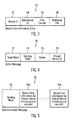
- FIG. 3 illustrates an embodiment of a device error information entry 50, which may comprise an instance or entry of the device error information 24 providing error information for one shared device 6a, 6b...6n.
- the device error information entry 50 includes a shared device identifier (ID) 52 for which the information is provided; a node owner ID 54 indicating the node 2a, 2b...2m that owns the identified shared device 52; an error counter 56 indicated a number of errors counted for the device 52 by the node owner 54, which may be the node at which the information is maintained or another node 2a, 2b...2m; and additional error information 58, such as counter start time and end time.
- ID shared device identifier
- FIG. 4 illustrates an embodiment of an action message 70 transmitted by an owning node 2a, 2b...2m to the other non-owning nodes 2a, 2b...2m when performing an action with respect to the error counter 56 for the shared device 6a, 6b...6n.
- the action may comprise opening, expiring or incrementing the error counter 56.
- FIG. 5 illustrates an embodiment of a synchronization message 90 sent by the owning node 2a, 2b...2m when transmitting error information 94a...94n for owned nodes to other non-owning nodes 2a, 2b...2m.
- the message 90 identifies the sending node 92 and includes device error information 94a...94n, such as the device error information 50 for each shared device 6a, 6b...6n owned by the sending node 92.
- nodes other than the owning node 2a, 2b...2m may send information on device error information.
- FIG. 6 illustrates an embodiment of operations performed by the device manager 22 executing in an owning node 2a, 2b...2m to perform an action with respect to an error counter 56.
- the owning node 2a, 2b...2m performs an action with respect to an error counter 56 for a shared device 6a, 6b...6n the node 2a, 2b...2m owns, such as creating an error counter 56 to monitor a number of errors at the shared device 52, expiring or incrementing the error counter.
- the owning node 2a, 2b...2m transmits (at block 102) an action message 70 to the other nodes 2a, 2b...2m indicating the action performed with respect to the error counter 56 and the shared device 6a, 6b...6n.
- the action message 70 may be transmitted to the nodes 2a, 2b...2m indicated in the node list 26. If (at block 104) the error counter 56 exceeds an error threshold for the shared device, then the owning node 2a, 2b...2m initiates (at block 106) an error recovery operation for the shared device 6a, 6b...6n. Otherwise, control ends.
- the owning node 2a, 2b...2m may indicate additional error counter information, such as a start time the counter was created, current timestamp, end time if the action was to expire the error counter, etc.
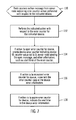
- FIG. 7 illustrates an embodiment of operations performed by the device manager 22 executing in a node 2a, 2b...2m upon receiving the action message 70.
- the receiving node 2a, 2b...2m performs the indicated action 76 with respect to the error counter for the indicated device.
- the device manager 22 creates a device error counter 56 indicating device ID 52, counter value set to 0, owning node 54 sending the open message, and additional information 58, such as start time of the error counter. If (at block 136) the action 76 is to increment the error counter 56 for the shared device 6a, 6b...6n, then the device manager 22 increments the error counter 56 the receiving node 2a, 2b...2m maintains. If (at block 138) the action 76 is to expire the error counter for the shared device 6a, 6b...6n, then the device manager 22 indicates the end time in the device error information.
- FIG. 8 illustrates an embodiment of operations performed by the device manager 22 executing in a node 2a, 2b...2m taking over ownership of a shared device 6a, 6b...6n.
- the new owning node 2a, 2b...2m updates (at block 152) the device error information entry 50 for the shared device 6a, 6b...6n to indicate that node 2a, 2b...2m now owns the shared device 6a, 6b...6n and uses the error counter 56 including information on updates to the error counter 56 initiated by the previous owning node 2a, 2b...2m.
- the new owning node 2a, 2b...2m takes over the error management operations of the previous owning node taking into account the previous errors counted by the previous owning node 2a, 2b...2m.
- FIG. 9 illustrates an embodiment of operations performed by the device manager 22 executing in a node 2a, 2b...2m to perform a synchronization operation.
- the node 2a, 2b...2m performs a synchronization operation.
- the synchronization operation may be performed periodically or in response to an event, such as some or all of the nodes 2a, 2b...2m rebooting and requesting to rejoin the nodal system.
- the node 2a, 2b...2m For each shared device 6a, 6b...6n the node 2a, 2b...2m owns, the node 2a, 2b...2m broadcasts (at block 172) a synchronization message 90 to all other nodes 2a, 2b...2m indicating the sending node 92 and device error information 50 for the owned shared devices 6a, 6b...6n including the error counter 56.
- the device error information 50 for each owned shared device 6a, 6b...6n is included in a separate error information section 94a...94n of the synchronization message 90.
- the synchronization message 90 may be transmitted to node 2a, 2b...2m in the node list 26.
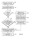
- FIG. 10 illustrates an embodiment of operations performed by the device manager 22 executing in a node 2a, 2b...2m to process a synchronization message 90 from one or more other nodes 2a, 2b...2m.
- the receiving node 2a, 2b...2m Upon receiving (at block 200) a synchronization message 90, the receiving node 2a, 2b...2m performs the operations at blocks 204 through 214 for each shared device 6a, 6b...6n indicated in the error information 94a...94n in the synchronization message 90.
- the device manager 22 creates (at block 206) a device error information entry 50 for the shared device 6a, 6b...6n including an error counter 56 to maintain in the local device error information 24.
- the created device error information entry 50 fields 52, 54, 56, and 58 are set to the values indicated in the synchronization message 90 for the shared device 6a, 6b...6n.
- the local copy of the device error information entry 50 being synchronized maintains the largest error counter value 56 between the values currently maintained in the local device error information entry 50 and in the synchronization message 90.
- FIG. 11 illustrates an embodiment of operations performed by the device manager 22 executing in a node 2a, 2b...2m to rejoin the system after a reboot, such as if the node 2a, 2b...2m is taken offline for error recovery or failure purposes, for a code upgrade, and for other purposes.
- the device manager 22 sends (at block 252) a rejoin message to the other node 2a, 2b...2m, indicated in the node list 26, requesting synchronization information so the rejoining node 2a, 2b...2m obtains current device error information 50.
- the device manager 22 Upon receiving (at block 254) synchronization messages 90, the device manager 22 performs (at block 256) the operations in FIG. 10 to update the local device error information 24 from the received synchronization messages 90.
- FIG. 12 illustrates a storage server 300 embodiment in which the nodes are implemented as clusters 304a and 304b in the server 300.
- the clusters 304a, 304b each include a processor complex 306a, 306b and a device manager 308a, 308b, which may perform the operations of the device manager 22 described above.
- the clusters 304a, 304b communicate over a bus 310.
- the system 300 receives Input/Output (I/O) requests from host systems 312a, 312b...312n over a network 314 directed toward storages 316a, 316b each configured to have one or more volumes 318a, 318b (e.g., Logical Unit Numbers, Logical Devices, etc.).
- I/O Input/Output
- the clusters 304a, 304b may receive I/O requests from the hosts 312a, 312b...312n and buffer the requests and write data in a cache (not shown) to the storage 316a, 316b.
- the clusters 304a, 304b may have different power boundaries.
- Each storage cluster 304a, 304b provides access to attached storage 316a, 316b.
- the device adaptors 320a, 320b...320n there are two sets of shared devices, the device adaptors 320a, 320b...320n and network adaptors 322a, 322b...322n.
- the clusters 304a, 304b communicate with the device adaptors 320a, 320b...320n via interface 324 and the network adaptors 322a, 322b...322n via interface 326.
- the device adaptors 320a, 320b...320n communicate with the storages 316a, 316b via interface 328.
- the interfaces 324, 326, and 328 may comprise a bus, such as a Peripheral Interconnect Bus (PCI) or other suitable interface hardware known in the art.
- PCI Peripheral Interconnect Bus
- the clusters 304a, 304b operate as the above described device managers 308a, 308b and may perform the operations described above with respect to device manager 22 and FIGs. 6-11 .
- the adaptors 320a, 320b...320n and 322a, 322b....322n may operate as the shared device 306a, 306b...306n, where the clusters 304a, 304b may be designated as owners of specific of the devices 320a, 320b...320n, 322a, 322b....322n.
- the system 302 may comprise a storage controller or server. In an alternative embodiment, the system 302 may comprise different types of computer devices that perform initialization and configuration operations of connected devices.
- the hosts 314a, 314b...314n may comprise computing devices known in the art, such as serves, mainframe, workstation, personal computer, hand held computer, laptop, telephony device, network appliance, etc.
- the network 314 may comprise a Storage Area Network (SAN), Local Area Network (LAN), Intranet, the Internet, Wide Area Network (WAN), etc.
- SAN Storage Area Network
- LAN Local Area Network
- WAN Wide Area Network
- the storage 8a, 8b may comprise an array of storage devices, such as a Just a Bunch of Disks (JBOD), Direct Access Storage Device (DASD), Redundant Array of Independent Disks (RAID) array, virtualization device, tape storage, flash memory, etc.
- JBOD Just a Bunch of Disks
- DASD Direct Access Storage Device
- RAID Redundant Array of Independent Disks
- Described embodiments provide techniques where a node maintains a local copy of device error information, including an error counter, for shared devices owned by other nodes that is updated when the owning nodes perform actions with respect to their device error information 50, such as update the error counter 56 upon receiving an error message from the shared device 6a, 6b...6n.
- the device error information is used by a node taking over ownership of another node, such that the node taking over has the current error information used by the node relinquishing the shared device 6a, 6b...6n.
- the new owning node may take over error management operations from a current error state at the shared device 6a, 6b...6n as maintained by the previous owning node.
- the described operations may be implemented as a method, apparatus or article of manufacture using standard programming and/or engineering techniques to produce software, firmware, hardware, or any combination thereof.
- the described operations may be implemented as code maintained in a "computer readable storage medium", where a processor may read and execute the code from the computer storage readable medium.
- a computer readable storage medium may comprise storage media such as magnetic storage medium (e.g., hard disk drives, floppy disks, tape, etc.), optical storage (CD-ROMs, DVDs, optical disks, etc.), volatile and non-volatile memory devices (e.g., EEPROMs, ROMs, PROMS, RAMs, DRAMs, SRAMs, Flash Memory, firmware, programmable logic, etc.), etc.
- the code implementing the described operations may further be implemented in hardware logic implemented in a hardware device (e.g., an integrated circuit chip, Programmable Gate Array (PGA), Application Specific Integrated Circuit (ASIC), etc.). Still further, the code implementing the described operations may be implemented in "transmission signals", where transmission signals may propagate through space or through a transmission media, such as an optical fiber, copper wire, etc.
- the transmission signals in which the code or logic is encoded may further comprise a wireless signal, satellite transmission, radio waves, infrared signals, Bluetooth, etc.
- the “article of manufacture” may comprise a transmitting station and/or a receiving station for transmitting and receiving transmission signals in which the code or logic is encoded, where the code or logic encoded in the transmission signal may be decoded and stored in hardware or a computer readable storage medium at the receiving and transmitting stations or devices.
- An “article of manufacture” comprises a computer readable storage medium, hardware device, and/or transmission transmitters or receivers in which code or logic may be implemented.
- an embodiment means “one or more (but not all) embodiments of the present invention(s)" unless expressly specified otherwise.
- variable references such as "n” or “m”, etc., to denote a number of instances of an item may refer to any integer number of instances of the item, where different variables may comprise the same number or different numbers. Further, a same variable reference used with different elements may denote a same or different number of instances of those elements.
- Devices that are in communication with each other need not be in continuous communication with each other, unless expressly specified otherwise.
- devices that are in communication with each other may communicate directly or indirectly through one or more intermediaries.
- FIGs. 6 , 7 , 8, 9 , 10 , and 11 show certain events occurring in a certain order. In alternative embodiments, certain operations may be performed in a different order, modified or removed. Moreover, steps may be added to the above described logic and still conform to the described embodiments. Further, operations described herein may occur sequentially or certain operations may be processed in parallel. Yet further, operations may be performed by a single processing unit or by distributed processing units.
Landscapes
- Engineering & Computer Science (AREA)
- Computer Networks & Wireless Communication (AREA)
- Signal Processing (AREA)
- Hardware Redundancy (AREA)
- Computer And Data Communications (AREA)
Description
- The present invention relates to a method, system, and computer program for synchronizing device error information among nodes.
- Host systems in a storage network may communicate with a storage controller through multiple paths. The storage controller may be comprised of separate storage clusters or nodes, where each storage cluster is capable of accessing the storage and provide redundancy to access the storage. Hosts may access the attached storage through either cluster. If a storage cluster fails, then the host may failover to using the other storage cluster to access the storage.
- In redundant storage controller environments, it is common for each storage node or cluster to establish ownership of certain external resources, such as network and Input/Output device adaptors. If a node in the system fails, other nodes in the system can take ownership of the resources that were owned by the failing node. If an external resource in the system starts reporting errors, the owning node will begin thresholding these errors and taking appropriate system recovery actions based on the number of detected errors. If, during this process, the owning node fails, another available node takes ownership of the external resource, but may have no knowledge of the previous errors that were recorded by the failing node. This causes the new owning node to treat the next error on the external resource as if it were the first error.
- Further, if the multiple errors reported by the external resource somehow caused the previous owning node to fail, then the new owning node will go through the same actions as the previous node, which could result in the new owning node failing in the same way. If other nodes in the system continue to take ownership of the resource, it could result in all nodes failing, causing the customer to lose access to data. Restarting the recovery operation from a zero error count may cause the overall system recovery (taken by the previous owning node and the new owning node) to take long enough such that the host system times out and the customer loses access to data.
- The Document
US 7092768 ("Distributed Control System") discloses a system for controlling a plurality of (multimedia) devices which keep each other and the controller updated about the device status in order to coordinate the various actions of the multimedia devices. DocumentWO9620547 - There is a need in the art for improved techniques to maintain error information for shared devices accessed by multiple nodes.
- Provided are a method, system, and computer program for synchronizing device error information among nodes. A first node performs an action with respect to a first node error counter for a device in communication with the first node and a second node. The first node transmits a message to the second node indicating the device and the action performed with respect to the first node error counter for the device. The second node performs the action indicated in the message with respect to a second node error counter for the device indicated in the message, wherein the second node error counter corresponds to the first node error counter for the device. When the first node detects an error at the device, the first node performs the action by incrementing the first node error counter for the device in response to detecting the error. The action indicated in the message comprises an increment action. The second node performs the increment action by incrementing the second node error counter for the device at the second node.
- In a further embodiment, the action indicated in the message comprises an open action. The second node performs the open action by creating the second node error counter for the device in response to the message.
- In a further embodiment, the action indicated in the message comprises an expire action. The second node performs the expire action by expiring the second error counter for the device in response to the message.
- In a further embodiment, the first node initiates an error recovery operation in response to the error counter value reaching an error threshold.
- In a further embodiment, the first node operates as an owner of the device performing error handling for the device. The second node takes over ownership of the device and increments the second node error counter indicating errors at the device detected by the first node in response to the second node detecting an error at the device.
- In a further embodiment, the second node takes over the ownership of the device in response to a failure of the first node.
- In a further embodiment, the device comprises a first device, the first node error counter comprises a first node first device error counter, and the second node error counter comprises a second error first device counter copy. The second node maintains a second node second device error counter indicating a number of errors at a second device in communication with the first node and the second node. The first node maintains a first node second device error counter indicating a number of errors at the second device including errors detected by the second node.
- In a further embodiment, the first and second nodes comprise first and second processing clusters in a server that communicate over a first interface in the server, wherein the first and second devices comprise first and second network adaptors, and wherein the first and second processing clusters communicate with the first and second adaptors over a second interface.
- In a further embodiment, the second node receives an error message from the second device. The second node increments the second node second device error counter. The second node transmits an increment message to the first node for the second device. The first node increments the first node second device error counter to the second error counter value in response to the increment message.
- In a further embodiment, the first node operates as an owner of the first device performing error handling for the first device and the second node operates as an owner of the second device performing error handling for the second device. The second node takes over ownership of the first device and uses the second node first device error counter to perform error management for the first device. The first node takes over ownership of the second device and uses the first node second device error counter to perform error management for the second device.
- In a further embodiment, a synchronization operation is initiated at the first and second nodes. The first node sends a synchronization message to the second node indicating a value of the first node first device error counter to the second node in response to the synchronization operation. The second node sends a synchronization message to the first node indicating a value of the second node second device error counter to the first node in response to the synchronization operation.
- In a further embodiment, the first node updates the first node second device error counter with the value of the second node second device error counter indicated in the synchronization message sent to the first node in response to the first node determining that the value indicated in the synchronization message is greater than the first node second device error counter. The second node updates the second node first device error counter with the value of the first node first device error counter indicated in the synchronization message sent to the second node in response to the second node determining that the value indicated in the synchronization message sent to the second node is greater than the second node first device error counter.
- In a further embodiment, the first node generates the first node second device error counter in response to determining that first node does not include the first node second device error counter for the second device. The first node sets the first node second device error counter to the value indicated in the synchronization message sent to the first node. The second node generates the second node first device error counter in response to determining that the second node does not include the second node first device error counter for the first device. The second node sets the second node first device error counter to the value indicated in the synchronization message sent to the second node.
- In a further embodiment, the second node initiates a reinitialization operation. The second node sends a join message to the first node as part of the reinitialization operation. The first node sends a message to the second node indicating a value of the first node error counter for the device in response to the join message. The second node updates the second node error counter to the value indicated in the message sent in response to the join message.
- Embodiments of the invention will now be described, by way of example only, with reference to the attached drawings in which:
-
FIG. 1 illustrates an embodiment of a computing environment. -
FIG. 2 illustrates an embodiment of node components. -
FIG. 3 illustrates an embodiment of device error information. -
FIG. 4 illustrates an embodiment of an action message. -
FIG. 5 illustrates an embodiment of a synchronization message. -
FIG. 6 illustrates an embodiment of node operations to transmit a message for an action performed with respect to an error counter for a device. -
FIG. 7 illustrates an embodiment of node operations to process a message concerning the action performed with respect to the error counter. -
FIG. 8 illustrates an embodiment of node operations to take ownership of a shared device. -
FIG. 9 illustrates an embodiment of node operations to perform a synchronization operation. -
FIG. 10 illustrates an embodiment of node operations to process a received synchronization message. -
FIG. 11 illustrates an embodiment of node operations to rejoin the system. -
FIG. 12 illustrates an embodiment of a storage server computing environment -
FIG. 1 illustrates an embodiment of a network computing environment. A plurality ofcomputational nodes first interface 4 and thenodes devices second interface 8. Thenodes devices nodes devices second interfaces second interfaces second interfaces second interface 8 may comprise a bus, network, loop, etc. -
FIG. 2 illustrates an embodiment of components of anode 2, which may comprise thenodes node 2 includes aprocessor 20 and adevice manager 22 to perform management operations with respect to the shareddevices device manager 22 maintainsdevice error information 24 for each of the shareddevices node 2 and devices owned byother nodes node list 26 comprises the network address and information onnodes devices devices device device -
FIG. 3 illustrates an embodiment of a deviceerror information entry 50, which may comprise an instance or entry of thedevice error information 24 providing error information for one shareddevice error information entry 50 includes a shared device identifier (ID) 52 for which the information is provided; anode owner ID 54 indicating thenode device 52; anerror counter 56 indicated a number of errors counted for thedevice 52 by thenode owner 54, which may be the node at which the information is maintained or anothernode additional error information 58, such as counter start time and end time. -
FIG. 4 illustrates an embodiment of anaction message 70 transmitted by an owningnode non-owning nodes error counter 56 for the shareddevice error counter 56. -
FIG. 5 illustrates an embodiment of asynchronization message 90 sent by the owningnode error information 94a...94n for owned nodes to othernon-owning nodes message 90 identifies the sendingnode 92 and includesdevice error information 94a...94n, such as thedevice error information 50 for each shareddevice node 92. In a further embodiment, nodes other than the owningnode -
FIG. 6 illustrates an embodiment of operations performed by thedevice manager 22 executing in an owningnode error counter 56. Atblock 100, the owningnode error counter 56 for a shareddevice node error counter 56 to monitor a number of errors at the shareddevice 52, expiring or incrementing the error counter. In response, the owningnode action message 70 to theother nodes error counter 56 and the shareddevice action message 70 may be transmitted to thenodes node list 26. If (at block 104) theerror counter 56 exceeds an error threshold for the shared device, then the owningnode device error information entry 50 to create theerror counter 56 for thedevice 52, the owningnode -
FIG. 7 illustrates an embodiment of operations performed by thedevice manager 22 executing in anode action message 70. Upon anon-owning node action message 70 from the owning node indicatingerror counter action 76 performed with respect to the indicateddevice 78, the receivingnode indicated action 76 with respect to the error counter for the indicated device. If (at block 134) theaction 76 is to create anerror counter 56 for theindicated device 78, device, then thedevice manager 22 creates adevice error counter 56 indicatingdevice ID 52, counter value set to 0, owningnode 54 sending the open message, andadditional information 58, such as start time of the error counter. If (at block 136) theaction 76 is to increment theerror counter 56 for the shareddevice device manager 22 increments theerror counter 56 the receivingnode action 76 is to expire the error counter for the shareddevice device manager 22 indicates the end time in the device error information. -
FIG. 8 illustrates an embodiment of operations performed by thedevice manager 22 executing in anode device device node node error information entry 50 for the shareddevice node device error counter 56 including information on updates to theerror counter 56 initiated by the previous owningnode node node -
FIG. 9 illustrates an embodiment of operations performed by thedevice manager 22 executing in anode block 170, thenode nodes device node node synchronization message 90 to allother nodes node 92 anddevice error information 50 for the owned shareddevices error counter 56. Thedevice error information 50 for each owned shareddevice error information section 94a...94n of thesynchronization message 90. Thesynchronization message 90 may be transmitted tonode node list 26. -
FIG. 10 illustrates an embodiment of operations performed by thedevice manager 22 executing in anode synchronization message 90 from one or moreother nodes synchronization message 90, the receivingnode blocks 204 through 214 for each shareddevice error information 94a...94n in thesynchronization message 90. If (at block 204) thenode error information entry 50 for the shareddevice device manager 22 creates (at block 206) a deviceerror information entry 50 for the shareddevice error counter 56 to maintain in the localdevice error information 24. The created deviceerror information entry 50fields synchronization message 90 for the shareddevice - If (at bock 204) there is a local device
error information entry 50 for the shareddevice error counter 56 in the localdevice error information 50 is less than the counter value indicated in thesynchronization message 90 for the shareddevice error counter 56 in the localdevice error information 50 is set to the error counter value indicated in thesynchronization message 90. Otherwise, if (at block 210) the localdevice error information 50error counter 56 is greater than the value for the error counter indicated in thesynchronization message 90, then the deviceerror information entry 50 is updated (block 214) with information other than the error counter value indicated in thesynchronization message 90. - With the operations of
FIG. 10 , the local copy of the deviceerror information entry 50 being synchronized maintains the largesterror counter value 56 between the values currently maintained in the local deviceerror information entry 50 and in thesynchronization message 90. -
FIG. 11 illustrates an embodiment of operations performed by thedevice manager 22 executing in anode node node device manager 22 sends (at block 252) a rejoin message to theother node node list 26, requesting synchronization information so the rejoiningnode device error information 50. Upon receiving (at block 254)synchronization messages 90, thedevice manager 22 performs (at block 256) the operations inFIG. 10 to update the localdevice error information 24 from the receivedsynchronization messages 90. -
FIG. 12 illustrates astorage server 300 embodiment in which the nodes are implemented asclusters server 300. Theclusters device manager 22 described above. Theclusters bus 310. Thesystem 300 receives Input/Output (I/O) requests fromhost systems network 314 directed towardstorages more volumes clusters hosts storage clusters storage cluster storage - In the embodiment of
FIG. 12 , there are two sets of shared devices, thedevice adaptors network adaptors clusters device adaptors interface 324 and thenetwork adaptors interface 326. Thedevice adaptors storages interface 328. Theinterfaces - In the embodiment of
FIG. 12 , theclusters device manager 22 andFIGs. 6-11 . Theadaptors clusters devices - The system 302 may comprise a storage controller or server. In an alternative embodiment, the system 302 may comprise different types of computer devices that perform initialization and configuration operations of connected devices. The hosts 314a, 314b...314n may comprise computing devices known in the art, such as serves, mainframe, workstation, personal computer, hand held computer, laptop, telephony device, network appliance, etc. The
network 314 may comprise a Storage Area Network (SAN), Local Area Network (LAN), Intranet, the Internet, Wide Area Network (WAN), etc. The storage 8a, 8b may comprise an array of storage devices, such as a Just a Bunch of Disks (JBOD), Direct Access Storage Device (DASD), Redundant Array of Independent Disks (RAID) array, virtualization device, tape storage, flash memory, etc. - Described embodiments provide techniques where a node maintains a local copy of device error information, including an error counter, for shared devices owned by other nodes that is updated when the owning nodes perform actions with respect to their
device error information 50, such as update theerror counter 56 upon receiving an error message from the shareddevice device device - The described operations may be implemented as a method, apparatus or article of manufacture using standard programming and/or engineering techniques to produce software, firmware, hardware, or any combination thereof. The described operations may be implemented as code maintained in a "computer readable storage medium", where a processor may read and execute the code from the computer storage readable medium. A computer readable storage medium may comprise storage media such as magnetic storage medium (e.g., hard disk drives, floppy disks, tape, etc.), optical storage (CD-ROMs, DVDs, optical disks, etc.), volatile and non-volatile memory devices (e.g., EEPROMs, ROMs, PROMS, RAMs, DRAMs, SRAMs, Flash Memory, firmware, programmable logic, etc.), etc. The code implementing the described operations may further be implemented in hardware logic implemented in a hardware device (e.g., an integrated circuit chip, Programmable Gate Array (PGA), Application Specific Integrated Circuit (ASIC), etc.). Still further, the code implementing the described operations may be implemented in "transmission signals", where transmission signals may propagate through space or through a transmission media, such as an optical fiber, copper wire, etc. The transmission signals in which the code or logic is encoded may further comprise a wireless signal, satellite transmission, radio waves, infrared signals, Bluetooth, etc. The "article of manufacture" may comprise a transmitting station and/or a receiving station for transmitting and receiving transmission signals in which the code or logic is encoded, where the code or logic encoded in the transmission signal may be decoded and stored in hardware or a computer readable storage medium at the receiving and transmitting stations or devices. An "article of manufacture" comprises a computer readable storage medium, hardware device, and/or transmission transmitters or receivers in which code or logic may be implemented. Those skilled in the art will recognize that many modifications may be made to this configuration without departing from the scope of the present invention, and that the article of manufacture may comprise suitable information bearing medium known in the art.
- The terms "an embodiment", "embodiment", "embodiments" "the embodiment", "the embodiments", "one or more embodiments", "some embodiments", and "one embodiment" mean "one or more (but not all) embodiments of the present invention(s)" unless expressly specified otherwise.
- The terms "including", "comprising", "having" and variations thereof mean "including but not limited to", unless expressly specified otherwise.
- The enumerated listing of items does not imply that any or all of the items are mutually exclusive, unless expressly specified otherwise.
- The terms "a", "an" and "the" mean "one or more", unless expressly specified otherwise.
- The use of variable references, such as "n" or "m", etc., to denote a number of instances of an item may refer to any integer number of instances of the item, where different variables may comprise the same number or different numbers. Further, a same variable reference used with different elements may denote a same or different number of instances of those elements.
- Devices that are in communication with each other need not be in continuous communication with each other, unless expressly specified otherwise. In addition, devices that are in communication with each other may communicate directly or indirectly through one or more intermediaries.
- A description of an embodiment with several components in communication with each other does not imply that all such components are required. On the contrary a variety of optional components are described to illustrate the wide variety of possible embodiments of the present invention.
- Further, although process steps, method steps, algorithms or the like may be described in a sequential order, such processes, methods and algorithms may be configured to work in alternate orders. In other words, any sequence or order of steps that may be described does not necessarily indicate a requirement that the steps be performed in that order. The steps of processes described herein may be performed in any order practical. Further, some steps may be performed simultaneously.
- When a single device or article is described herein, it will be readily apparent that more than one device/article (whether or not they cooperate) may be used in place of a single device/article. Similarly, where more than one device or article is described herein (whether or not they cooperate), it will be readily apparent that a single device/article may be used in place of the more than one device or article or a different number of devices/articles may be used instead of the shown number of devices or programs. The functionality and/or the features of a device may be alternatively embodied by one or more other devices which are not explicitly described as having such functionality/features. Thus, other embodiments of the present invention need not include the device itself.
- The illustrated operations of
FIGs. 6 ,7 ,8, 9 ,10 , and11 show certain events occurring in a certain order. In alternative embodiments, certain operations may be performed in a different order, modified or removed. Moreover, steps may be added to the above described logic and still conform to the described embodiments. Further, operations described herein may occur sequentially or certain operations may be processed in parallel. Yet further, operations may be performed by a single processing unit or by distributed processing units. - The foregoing description of various embodiments of the invention has been presented for the purposes of illustration and description. It is not intended to be exhaustive or to limit the invention to the precise form disclosed. Many modifications and variations are possible in light of the above teaching. It is intended that the scope of the invention be limited not by this detailed description, but rather by the claims appended hereto. The above specification, examples and data provide a complete description of the manufacture and use of the composition of the invention. Since many embodiments of the invention can be made without departing from the scope of the invention, the invention resides in the claims hereinafter appended.
Claims (15)
- A method, comprising:performing (100), by a first node, an action with respect to a first node error counter for a device in communication with the first node and a second node;transmitting (102), by the first node, a message to the second node indicating the device and the action performed with respect to the first node error counter for the device;performing (130), by the second node, the action indicated in the message with respect to a second node error counter for the device indicated in the message, wherein the second node error counter corresponds to the first node error counter for the device; the method further comprising:detecting, by the first node, an error at the device, wherein the action performed by the first node comprises incrementing the first node error counter for the device in response to detecting the error, wherein the action indicated in the message comprises an increment action, wherein performing, by the second node, the increment action comprises incrementing the second node error counter for the device at the second node.
- The method of claim 1, wherein the action indicated in the message comprises an open action, wherein performing, by the second node, the open action comprises creating the second node error counter for the device in response to the message.
- The method of claim 1, wherein the action indicated in the message comprises an expire action, wherein performing, by the second node, the expire action comprises expiring the second error counter for the device in response to the message.
- The method of claim 1, further comprising:initiating, by the first node, an error recovery operation in response to the error counter value reaching an error threshold.
- The method of claim 1, wherein the first node operates as an owner of the device performing error handling for the device, further comprising:taking over, by the second node, ownership of the device; andincrementing, by the second node, the second node error counter, indicating errors at the device detected by the first node, in response to the second node detecting an error at the device.
- The method of claim 5, wherein the second node takes over the ownership of the device in response to a failure of the first node.
- The method of claim 1, wherein the device comprises a first device, the first node error counter comprises a first node first device error counter, and the second node error counter comprises a second error first device counter copy, further comprising:maintaining, by the second node, a second node second device error counter indicating a number of errors at a second device in communication with the first node and the second node;maintaining, by the first node, a first node second device error counter indicating a number of errors at the second device including errors detected by the second node.
- The method of claim 7, wherein the first and second nodes comprise first and second processing clusters in a server that communicate over a first interface in the server, wherein the first and second devices comprise first and second network adaptors, and wherein the first and second processing clusters communicate with the first and second adaptors over a second interface.
- The method of claim 7, further comprising:receiving, by the second node, an error message from the second device;
incrementing, by the second node, the second node second device error counter,transmitting, by the second node, an increment message to the first node for the second device;incrementing, by the first node, the first node second device error counter to the second error counter value in response to the increment message. - The method of claim 7, wherein the first node operates as an owner of the first device performing error handling for the first device and wherein the second node operates as an owner of the second device performing error handling for the second device, further comprising:taking over, by the second node, ownership of the first device, wherein the second node uses the second node first device error counter to perform error management for the first device; andtaking over, by the first node, ownership of the second device, wherein the first node uses the first node second device error counter to perform error management for the second device.
- The method of claim 7, further comprising:initiating a synchronization operation at the first and second nodes;sending, by the first node a synchronization message to the second node indicating a value of the first node first device error counter to the second node in response to the synchronization operation; andsending, by the second node a synchronization message to the first node indicating a value of the second node second device error counter to the first node in response to the synchronization operation.
- The method of claim 11, further comprising:updating, by the first node, the first node second device error counter with the value of the second node second device error counter indicated in the synchronization message sent to the first node in response to the first node determining that the value indicated in the synchronization message is greater than the first node second device error counter; andupdating, by the second node, the second node first device error counter with the value of the first node first device error counter indicated in the synchronization message sent to the second node in response to the second node determining that the value indicated in the synchronization message sent to the second node is greater than the second node first device error counter.
- The method of claim 11, further comprising:generating, by the first node, the first node second device error counter in response to determining that first node does not include the first node second device error counter for the second device;setting, by the first node, the first node second device error counter to the value indicated in the synchronization message sent to the first node;generating, by the second node, the second node first device error counter in response to determining that the second node does not include the second node first device error counter for the first device;setting, by the second node, the second node first device error counter to the value indicated in the synchronization message sent to the second node.
- A system comprising a first node and a second node in communication with a device, the system comprising means being adapted to execute program code to perform the steps as claimed in any of claims 1 to 13.
- A computer program product including code, which when executed by a first node and second node, wherein a device is in communication with the first node and the second node, adapts said first node and second node to perform the steps as defined in any of claims 1 to 13.
Applications Claiming Priority (2)
| Application Number | Priority Date | Filing Date | Title |
|---|---|---|---|
| US12/132,550 US7904752B2 (en) | 2008-06-03 | 2008-06-03 | Synchronizing device error information among nodes |
| PCT/EP2009/056557 WO2009147066A1 (en) | 2008-06-03 | 2009-05-28 | Synchronizing device error information among nodes |
Publications (2)
| Publication Number | Publication Date |
|---|---|
| EP2283612A1 EP2283612A1 (en) | 2011-02-16 |
| EP2283612B1 true EP2283612B1 (en) | 2013-04-03 |
Family
ID=41110621
Family Applications (1)
| Application Number | Title | Priority Date | Filing Date |
|---|---|---|---|
| EP09757448A Active EP2283612B1 (en) | 2008-06-03 | 2009-05-28 | Synchronizing device error information among nodes |
Country Status (6)
| Country | Link |
|---|---|
| US (1) | US7904752B2 (en) |
| EP (1) | EP2283612B1 (en) |
| JP (1) | JP5255697B2 (en) |
| KR (1) | KR101385910B1 (en) |
| CA (1) | CA2708976C (en) |
| WO (1) | WO2009147066A1 (en) |
Families Citing this family (5)
| Publication number | Priority date | Publication date | Assignee | Title |
|---|---|---|---|---|
| US8381026B2 (en) * | 2009-06-22 | 2013-02-19 | Citrix Systems, Inc. | Systems and method for transaction stall detection and propagating the result in a multi-core architecture |
| US8635318B1 (en) * | 2009-09-15 | 2014-01-21 | Symantec Corporation | Message broadcast protocol which handles configuration changes in a cluster of virtual servers |
| JP5785455B2 (en) * | 2011-07-29 | 2015-09-30 | インターナショナル・ビジネス・マシーンズ・コーポレーションInternational Business Machines Corporation | Apparatus and method for processing related to removable media |
| US10289466B2 (en) | 2017-02-01 | 2019-05-14 | International Business Machines Corporation | Error data collection improvements in storage network components |
| JP7338354B2 (en) * | 2019-09-20 | 2023-09-05 | 富士通株式会社 | Information processing equipment, information processing system and communication management program |
Family Cites Families (22)
| Publication number | Priority date | Publication date | Assignee | Title |
|---|---|---|---|---|
| IT1271326B (en) | 1994-12-23 | 1997-05-27 | Sits Soc It Telecom Siemens | PROCEDURE FOR AUTOMATIC REALIGNMENT IN THE EVENT REPORT IN A MANAGEMENT SYSTEM AND RELATED SYSTEM |
| JPH0955735A (en) * | 1995-08-10 | 1997-02-25 | Nippon Telegr & Teleph Corp <Ntt> | Communication network failure diagnosis system and communication network failure diagnosis method |
| JPH09259050A (en) * | 1996-03-19 | 1997-10-03 | Hitachi Ltd | Computer peripheral device control device error reporting method and peripheral device control device |
| US6098179A (en) | 1998-01-22 | 2000-08-01 | Digital Equipment Corporation | Method and apparatus for performing error detection |
| US6728216B1 (en) | 1998-02-27 | 2004-04-27 | Advanced Micro Devices, Inc. | Arrangement in a network repeater for monitoring link integrity and selectively down shifting link speed based on local configuration signals |
| JPH11296311A (en) * | 1998-04-08 | 1999-10-29 | Hitachi Ltd | Fault-tolerant control method for storage devices |
| US6510393B1 (en) * | 1998-12-21 | 2003-01-21 | Siemens Atkiengesellschaft | Method for detecting faults in a switching device |
| US6725281B1 (en) | 1999-06-11 | 2004-04-20 | Microsoft Corporation | Synchronization of controlled device state using state table and eventing in data-driven remote device control model |
| US6701449B1 (en) * | 2000-04-20 | 2004-03-02 | Ciprico, Inc. | Method and apparatus for monitoring and analyzing network appliance status information |
| US7209447B1 (en) | 2000-07-13 | 2007-04-24 | Tellabs Operations, Inc. | Method and apparatus for measuring packet connection quality of service |
| JP4185661B2 (en) * | 2000-11-17 | 2008-11-26 | キヤノン株式会社 | Device management apparatus, device management program, recording medium storing device management program, and device management method |
| US6865689B1 (en) * | 2001-06-29 | 2005-03-08 | Sun Microsystems, Inc. | Method and apparatus for fault isolation on network loops using low level error counters |
| JP2003069614A (en) | 2001-08-28 | 2003-03-07 | Nec Miyagi Ltd | Data transmission device |
| JP2003345679A (en) * | 2002-05-28 | 2003-12-05 | Nippon Telegr & Teleph Corp <Ntt> | Server system, mediation device, and error concealment method in client-server type system |
| US7287193B2 (en) * | 2003-05-15 | 2007-10-23 | International Business Machines Corporation | Methods, systems, and media to correlate errors associated with a cluster |
| US7092768B1 (en) | 2004-03-09 | 2006-08-15 | Liquid Sky Studios, Inc. | Distributed control system |
| US7539932B2 (en) | 2004-06-17 | 2009-05-26 | International Business Machines Corporation | Method and system for debugging Ethernet |
| US7624305B2 (en) * | 2004-11-18 | 2009-11-24 | International Business Machines Corporation | Failure isolation in a communication system |
| US7254768B2 (en) | 2005-02-18 | 2007-08-07 | Broadcom Corporation | Memory command unit throttle and error recovery |
| US7523359B2 (en) * | 2005-03-31 | 2009-04-21 | International Business Machines Corporation | Apparatus, system, and method for facilitating monitoring and responding to error events |
| JP2006164304A (en) * | 2006-01-20 | 2006-06-22 | Hitachi Ltd | Array type disk device, program and method for preventing double failure of drive |
| JP2008083896A (en) * | 2006-09-27 | 2008-04-10 | Fujitsu Ltd | Anomaly source identification method, system operation method, base station control system operation method, and processing system |
-
2008
- 2008-06-03 US US12/132,550 patent/US7904752B2/en not_active Expired - Fee Related
-
2009
- 2009-05-28 WO PCT/EP2009/056557 patent/WO2009147066A1/en not_active Ceased
- 2009-05-28 EP EP09757448A patent/EP2283612B1/en active Active
- 2009-05-28 KR KR1020107027344A patent/KR101385910B1/en not_active Expired - Fee Related
- 2009-05-28 CA CA2708976A patent/CA2708976C/en active Active
- 2009-05-28 JP JP2011512077A patent/JP5255697B2/en active Active
Also Published As
| Publication number | Publication date |
|---|---|
| JP2011524563A (en) | 2011-09-01 |
| US7904752B2 (en) | 2011-03-08 |
| CA2708976A1 (en) | 2009-12-10 |
| WO2009147066A1 (en) | 2009-12-10 |
| CA2708976C (en) | 2015-04-21 |
| EP2283612A1 (en) | 2011-02-16 |
| US20090300436A1 (en) | 2009-12-03 |
| JP5255697B2 (en) | 2013-08-07 |
| KR101385910B1 (en) | 2014-04-15 |
| WO2009147066A4 (en) | 2010-02-11 |
| KR20110022587A (en) | 2011-03-07 |
Similar Documents
| Publication | Publication Date | Title |
|---|---|---|
| US8055865B2 (en) | Managing write requests to data sets in a primary volume subject to being copied to a secondary volume | |
| CN103201724B (en) | Providing application high availability in highly-available virtual machine environments | |
| JP5147941B2 (en) | Method, system, and computer program for managing write copies from primary storage to secondary storage over different networks | |
| CN100470494C (en) | Cluster availability management method and system | |
| EP3179359B1 (en) | Data sending method, data receiving method, and storage device | |
| US8726274B2 (en) | Registration and initialization of cluster-aware virtual input/output server nodes | |
| CN100568881C (en) | Method and system for selecting a storage cluster for accessing storage devices | |
| US20050283641A1 (en) | Apparatus, system, and method for verified fencing of a rogue node within a cluster | |
| US20080046612A1 (en) | Method, apparatus and program storage device for providing asynchronous status messaging in a data storage system | |
| JP2012528382A (en) | Cache data processing using cache clusters in configurable mode | |
| TW200805079A (en) | Consolidating session information for a cluster of sessions in a coupled session environment | |
| CA2708976C (en) | Synchronizing device error information among nodes | |
| US9411536B2 (en) | Verifying a record as part of an operation to modify the record | |
| EP3167372B1 (en) | Methods for facilitating high availability storage services and corresponding devices | |
| US7904682B2 (en) | Copying writes from primary storages to secondary storages across different networks | |
| US20070078809A1 (en) | Robust data availability system having decentralized storage and multiple access paths | |
| US9830263B1 (en) | Cache consistency | |
| EP4250119A1 (en) | Data placement and recovery in the event of partition failures | |
| CN106254445A (en) | Message sending method and server | |
| US7783931B2 (en) | Alternate communication path between ESSNI server and CEC | |
| JP5490067B2 (en) | Fault management apparatus and program | |
| JP5425146B2 (en) | Fault management apparatus and program | |
| HK1229912A1 (en) | Systems and methods for fault tolerant communications |
Legal Events
| Date | Code | Title | Description |
|---|---|---|---|
| PUAI | Public reference made under article 153(3) epc to a published international application that has entered the european phase |
Free format text: ORIGINAL CODE: 0009012 |
|
| 17P | Request for examination filed |
Effective date: 20100908 |
|
| AK | Designated contracting states |
Kind code of ref document: A1 Designated state(s): AT BE BG CH CY CZ DE DK EE ES FI FR GB GR HR HU IE IS IT LI LT LU LV MC MK MT NL NO PL PT RO SE SI SK TR |
|
| AX | Request for extension of the european patent |
Extension state: AL BA RS |
|
| DAX | Request for extension of the european patent (deleted) | ||
| GRAP | Despatch of communication of intention to grant a patent |
Free format text: ORIGINAL CODE: EPIDOSNIGR1 |
|
| GRAS | Grant fee paid |
Free format text: ORIGINAL CODE: EPIDOSNIGR3 |
|
| GRAA | (expected) grant |
Free format text: ORIGINAL CODE: 0009210 |
|
| AK | Designated contracting states |
Kind code of ref document: B1 Designated state(s): AT BE BG CH CY CZ DE DK EE ES FI FR GB GR HR HU IE IS IT LI LT LU LV MC MK MT NL NO PL PT RO SE SI SK TR |
|
| REG | Reference to a national code |
Ref country code: GB Ref legal event code: FG4D |
|
| REG | Reference to a national code |
Ref country code: AT Ref legal event code: REF Ref document number: 605312 Country of ref document: AT Kind code of ref document: T Effective date: 20130415 Ref country code: CH Ref legal event code: NV Representative=s name: IBM RESEARCH GMBH ZURICH RESEARCH LABORATORY I, CH Ref country code: CH Ref legal event code: EP |
|
| REG | Reference to a national code |
Ref country code: IE Ref legal event code: FG4D |
|
| REG | Reference to a national code |
Ref country code: DE Ref legal event code: R096 Ref document number: 602009014641 Country of ref document: DE Effective date: 20130529 |
|
| REG | Reference to a national code |
Ref country code: GB Ref legal event code: 746 Effective date: 20130510 |
|
| REG | Reference to a national code |
Ref country code: AT Ref legal event code: MK05 Ref document number: 605312 Country of ref document: AT Kind code of ref document: T Effective date: 20130403 |
|
| PG25 | Lapsed in a contracting state [announced via postgrant information from national office to epo] |
Ref country code: SI Free format text: LAPSE BECAUSE OF FAILURE TO SUBMIT A TRANSLATION OF THE DESCRIPTION OR TO PAY THE FEE WITHIN THE PRESCRIBED TIME-LIMIT Effective date: 20130403 |
|
| REG | Reference to a national code |
Ref country code: NL Ref legal event code: VDEP Effective date: 20130403 |
|
| REG | Reference to a national code |
Ref country code: LT Ref legal event code: MG4D |
|
| REG | Reference to a national code |
Ref country code: DE Ref legal event code: R084 Ref document number: 602009014641 Country of ref document: DE Effective date: 20130516 |
|
| PG25 | Lapsed in a contracting state [announced via postgrant information from national office to epo] |
Ref country code: NL Free format text: LAPSE BECAUSE OF FAILURE TO SUBMIT A TRANSLATION OF THE DESCRIPTION OR TO PAY THE FEE WITHIN THE PRESCRIBED TIME-LIMIT Effective date: 20130403 Ref country code: PT Free format text: LAPSE BECAUSE OF FAILURE TO SUBMIT A TRANSLATION OF THE DESCRIPTION OR TO PAY THE FEE WITHIN THE PRESCRIBED TIME-LIMIT Effective date: 20130805 Ref country code: BE Free format text: LAPSE BECAUSE OF FAILURE TO SUBMIT A TRANSLATION OF THE DESCRIPTION OR TO PAY THE FEE WITHIN THE PRESCRIBED TIME-LIMIT Effective date: 20130403 Ref country code: FI Free format text: LAPSE BECAUSE OF FAILURE TO SUBMIT A TRANSLATION OF THE DESCRIPTION OR TO PAY THE FEE WITHIN THE PRESCRIBED TIME-LIMIT Effective date: 20130403 Ref country code: ES Free format text: LAPSE BECAUSE OF FAILURE TO SUBMIT A TRANSLATION OF THE DESCRIPTION OR TO PAY THE FEE WITHIN THE PRESCRIBED TIME-LIMIT Effective date: 20130714 Ref country code: IS Free format text: LAPSE BECAUSE OF FAILURE TO SUBMIT A TRANSLATION OF THE DESCRIPTION OR TO PAY THE FEE WITHIN THE PRESCRIBED TIME-LIMIT Effective date: 20130803 Ref country code: LT Free format text: LAPSE BECAUSE OF FAILURE TO SUBMIT A TRANSLATION OF THE DESCRIPTION OR TO PAY THE FEE WITHIN THE PRESCRIBED TIME-LIMIT Effective date: 20130403 Ref country code: NO Free format text: LAPSE BECAUSE OF FAILURE TO SUBMIT A TRANSLATION OF THE DESCRIPTION OR TO PAY THE FEE WITHIN THE PRESCRIBED TIME-LIMIT Effective date: 20130703 Ref country code: SE Free format text: LAPSE BECAUSE OF FAILURE TO SUBMIT A TRANSLATION OF THE DESCRIPTION OR TO PAY THE FEE WITHIN THE PRESCRIBED TIME-LIMIT Effective date: 20130403 Ref country code: AT Free format text: LAPSE BECAUSE OF FAILURE TO SUBMIT A TRANSLATION OF THE DESCRIPTION OR TO PAY THE FEE WITHIN THE PRESCRIBED TIME-LIMIT Effective date: 20130403 Ref country code: GR Free format text: LAPSE BECAUSE OF FAILURE TO SUBMIT A TRANSLATION OF THE DESCRIPTION OR TO PAY THE FEE WITHIN THE PRESCRIBED TIME-LIMIT Effective date: 20130704 |
|
| PG25 | Lapsed in a contracting state [announced via postgrant information from national office to epo] |
Ref country code: CY Free format text: LAPSE BECAUSE OF FAILURE TO SUBMIT A TRANSLATION OF THE DESCRIPTION OR TO PAY THE FEE WITHIN THE PRESCRIBED TIME-LIMIT Effective date: 20130403 Ref country code: LV Free format text: LAPSE BECAUSE OF FAILURE TO SUBMIT A TRANSLATION OF THE DESCRIPTION OR TO PAY THE FEE WITHIN THE PRESCRIBED TIME-LIMIT Effective date: 20130403 Ref country code: BG Free format text: LAPSE BECAUSE OF FAILURE TO SUBMIT A TRANSLATION OF THE DESCRIPTION OR TO PAY THE FEE WITHIN THE PRESCRIBED TIME-LIMIT Effective date: 20130703 Ref country code: HR Free format text: LAPSE BECAUSE OF FAILURE TO SUBMIT A TRANSLATION OF THE DESCRIPTION OR TO PAY THE FEE WITHIN THE PRESCRIBED TIME-LIMIT Effective date: 20130403 Ref country code: PL Free format text: LAPSE BECAUSE OF FAILURE TO SUBMIT A TRANSLATION OF THE DESCRIPTION OR TO PAY THE FEE WITHIN THE PRESCRIBED TIME-LIMIT Effective date: 20130403 |
|
| REG | Reference to a national code |
Ref country code: CH Ref legal event code: PL |
|
| PG25 | Lapsed in a contracting state [announced via postgrant information from national office to epo] |
Ref country code: CZ Free format text: LAPSE BECAUSE OF FAILURE TO SUBMIT A TRANSLATION OF THE DESCRIPTION OR TO PAY THE FEE WITHIN THE PRESCRIBED TIME-LIMIT Effective date: 20130403 Ref country code: MC Free format text: LAPSE BECAUSE OF FAILURE TO SUBMIT A TRANSLATION OF THE DESCRIPTION OR TO PAY THE FEE WITHIN THE PRESCRIBED TIME-LIMIT Effective date: 20130403 Ref country code: EE Free format text: LAPSE BECAUSE OF FAILURE TO SUBMIT A TRANSLATION OF THE DESCRIPTION OR TO PAY THE FEE WITHIN THE PRESCRIBED TIME-LIMIT Effective date: 20130403 Ref country code: CH Free format text: LAPSE BECAUSE OF NON-PAYMENT OF DUE FEES Effective date: 20130531 Ref country code: DK Free format text: LAPSE BECAUSE OF FAILURE TO SUBMIT A TRANSLATION OF THE DESCRIPTION OR TO PAY THE FEE WITHIN THE PRESCRIBED TIME-LIMIT Effective date: 20130403 Ref country code: SK Free format text: LAPSE BECAUSE OF FAILURE TO SUBMIT A TRANSLATION OF THE DESCRIPTION OR TO PAY THE FEE WITHIN THE PRESCRIBED TIME-LIMIT Effective date: 20130403 Ref country code: LI Free format text: LAPSE BECAUSE OF NON-PAYMENT OF DUE FEES Effective date: 20130531 |
|
| PLBE | No opposition filed within time limit |
Free format text: ORIGINAL CODE: 0009261 |
|
| STAA | Information on the status of an ep patent application or granted ep patent |
Free format text: STATUS: NO OPPOSITION FILED WITHIN TIME LIMIT |
|
| REG | Reference to a national code |
Ref country code: IE Ref legal event code: MM4A |
|
| PG25 | Lapsed in a contracting state [announced via postgrant information from national office to epo] |
Ref country code: IT Free format text: LAPSE BECAUSE OF FAILURE TO SUBMIT A TRANSLATION OF THE DESCRIPTION OR TO PAY THE FEE WITHIN THE PRESCRIBED TIME-LIMIT Effective date: 20130403 Ref country code: RO Free format text: LAPSE BECAUSE OF FAILURE TO SUBMIT A TRANSLATION OF THE DESCRIPTION OR TO PAY THE FEE WITHIN THE PRESCRIBED TIME-LIMIT Effective date: 20130403 |
|
| REG | Reference to a national code |
Ref country code: FR Ref legal event code: ST Effective date: 20140131 |
|
| 26N | No opposition filed |
Effective date: 20140106 |
|
| REG | Reference to a national code |
Ref country code: DE Ref legal event code: R097 Ref document number: 602009014641 Country of ref document: DE Effective date: 20140106 |
|
| PG25 | Lapsed in a contracting state [announced via postgrant information from national office to epo] |
Ref country code: IE Free format text: LAPSE BECAUSE OF NON-PAYMENT OF DUE FEES Effective date: 20130528 |
|
| PG25 | Lapsed in a contracting state [announced via postgrant information from national office to epo] |
Ref country code: FR Free format text: LAPSE BECAUSE OF NON-PAYMENT OF DUE FEES Effective date: 20130603 |
|
| PG25 | Lapsed in a contracting state [announced via postgrant information from national office to epo] |
Ref country code: MT Free format text: LAPSE BECAUSE OF FAILURE TO SUBMIT A TRANSLATION OF THE DESCRIPTION OR TO PAY THE FEE WITHIN THE PRESCRIBED TIME-LIMIT Effective date: 20130403 |
|
| PG25 | Lapsed in a contracting state [announced via postgrant information from national office to epo] |
Ref country code: TR Free format text: LAPSE BECAUSE OF FAILURE TO SUBMIT A TRANSLATION OF THE DESCRIPTION OR TO PAY THE FEE WITHIN THE PRESCRIBED TIME-LIMIT Effective date: 20130403 |
|
| PG25 | Lapsed in a contracting state [announced via postgrant information from national office to epo] |
Ref country code: MK Free format text: LAPSE BECAUSE OF FAILURE TO SUBMIT A TRANSLATION OF THE DESCRIPTION OR TO PAY THE FEE WITHIN THE PRESCRIBED TIME-LIMIT Effective date: 20130403 Ref country code: LU Free format text: LAPSE BECAUSE OF NON-PAYMENT OF DUE FEES Effective date: 20130528 Ref country code: HU Free format text: LAPSE BECAUSE OF FAILURE TO SUBMIT A TRANSLATION OF THE DESCRIPTION OR TO PAY THE FEE WITHIN THE PRESCRIBED TIME-LIMIT; INVALID AB INITIO Effective date: 20090528 |
|
| REG | Reference to a national code |
Ref country code: DE Ref legal event code: R082 Ref document number: 602009014641 Country of ref document: DE Representative=s name: KUISMA, SIRPA, FI |
|
| REG | Reference to a national code |
Ref country code: DE Ref legal event code: R079 Ref document number: 602009014641 Country of ref document: DE Free format text: PREVIOUS MAIN CLASS: H04L0012240000 Ipc: H04L0041000000 |
|
| P01 | Opt-out of the competence of the unified patent court (upc) registered |
Effective date: 20230423 |
|
| PGFP | Annual fee paid to national office [announced via postgrant information from national office to epo] |
Ref country code: DE Payment date: 20230510 Year of fee payment: 15 |
|
| REG | Reference to a national code |
Ref country code: DE Ref legal event code: R119 Ref document number: 602009014641 Country of ref document: DE |
|
| PG25 | Lapsed in a contracting state [announced via postgrant information from national office to epo] |
Ref country code: DE Free format text: LAPSE BECAUSE OF NON-PAYMENT OF DUE FEES Effective date: 20241203 |
|
| PGFP | Annual fee paid to national office [announced via postgrant information from national office to epo] |
Ref country code: GB Payment date: 20250520 Year of fee payment: 17 |