EP2282547A2 - Projection display apparatus and image adjustment method - Google Patents
Projection display apparatus and image adjustment method Download PDFInfo
- Publication number
- EP2282547A2 EP2282547A2 EP10008026A EP10008026A EP2282547A2 EP 2282547 A2 EP2282547 A2 EP 2282547A2 EP 10008026 A EP10008026 A EP 10008026A EP 10008026 A EP10008026 A EP 10008026A EP 2282547 A2 EP2282547 A2 EP 2282547A2
- Authority
- EP
- European Patent Office
- Prior art keywords
- image
- display apparatus
- test pattern
- projection
- projection display
- Prior art date
- Legal status (The legal status is an assumption and is not a legal conclusion. Google has not performed a legal analysis and makes no representation as to the accuracy of the status listed.)
- Withdrawn
Links
- 238000000034 method Methods 0.000 title claims description 17
- 238000012360 testing method Methods 0.000 claims abstract description 179
- 238000012545 processing Methods 0.000 claims description 85
- 238000012986 modification Methods 0.000 description 48
- 230000004048 modification Effects 0.000 description 48
- 239000004973 liquid crystal related substance Substances 0.000 description 32
- 230000010287 polarization Effects 0.000 description 24
- 238000001514 detection method Methods 0.000 description 11
- 230000003287 optical effect Effects 0.000 description 8
- 238000003708 edge detection Methods 0.000 description 7
- 239000000470 constituent Substances 0.000 description 6
- 239000003086 colorant Substances 0.000 description 5
- 230000000694 effects Effects 0.000 description 5
- 238000010586 diagram Methods 0.000 description 4
- 238000005286 illumination Methods 0.000 description 4
- 239000013598 vector Substances 0.000 description 4
- 238000012937 correction Methods 0.000 description 3
- 238000006243 chemical reaction Methods 0.000 description 2
- 239000011159 matrix material Substances 0.000 description 2
- 238000007781 pre-processing Methods 0.000 description 2
- 230000005540 biological transmission Effects 0.000 description 1
- 230000001419 dependent effect Effects 0.000 description 1
- 230000000452 restraining effect Effects 0.000 description 1
- 238000000926 separation method Methods 0.000 description 1
- 229910052724 xenon Inorganic materials 0.000 description 1
- FHNFHKCVQCLJFQ-UHFFFAOYSA-N xenon atom Chemical compound [Xe] FHNFHKCVQCLJFQ-UHFFFAOYSA-N 0.000 description 1
Images


Classifications
-
- H—ELECTRICITY
- H04—ELECTRIC COMMUNICATION TECHNIQUE
- H04N—PICTORIAL COMMUNICATION, e.g. TELEVISION
- H04N9/00—Details of colour television systems
- H04N9/12—Picture reproducers
- H04N9/31—Projection devices for colour picture display, e.g. using electronic spatial light modulators [ESLM]
- H04N9/3191—Testing thereof
- H04N9/3194—Testing thereof including sensor feedback
-
- H—ELECTRICITY
- H04—ELECTRIC COMMUNICATION TECHNIQUE
- H04N—PICTORIAL COMMUNICATION, e.g. TELEVISION
- H04N9/00—Details of colour television systems
- H04N9/12—Picture reproducers
- H04N9/31—Projection devices for colour picture display, e.g. using electronic spatial light modulators [ESLM]
- H04N9/3179—Video signal processing therefor
- H04N9/3185—Geometric adjustment, e.g. keystone or convergence
Definitions
- the present invention relates to a projection display apparatus having: a light valve configured to modulate light emitted from a light source; and a projection unit configured to project light emitted from the light valve on a projection plane. It also relates to an image adjustment method applied to the projection display apparatus.
- a projection display apparatus comprising: a light valve for modulating light emitted from a light source; and a projection unit for projecting light emitted from the light valve on a projection plane.
- the shape of an image projected on the projection plane is distorted depending upon a positional relationship between the projection display apparatus and the projection plane.
- the projection display apparatus projects a rectangular test pattern image on a projection plane.
- the projection display apparatus picks up the test pattern image projected on the projection plane and then specifies the coordinates at four corners of the test pattern image on the projection plane.
- the projection display apparatus specifies a positional relationship between the projection display apparatus and the projection plane, based upon the coordinates at the four corners of the test pattern image on the projection plane, and then, adjusts the shape of the image projected on the projection plane.
- an image pickup element for picking up a test pattern image is configured to output a pickup image along a predetermined line (for example, pixel array in a horizontal direction).
- the predetermined line is generally a line extending along a horizontal direction.
- a rectangular test pattern image is employed, and thus, among the four edges of the test pattern image, two edges are those extending along a horizontal direction. That is, among the four edges of the test pattern image, two edges are substantially parallel to the predetermined line.
- the projection display apparatus needs to specify the coordinates at the four edges or four corners of the test pattern image by performing edge detection or the like after acquiring all of pickup images from the image pickup element.
- a projection display apparatus has an imager configured to modulate light emitted from a light source and a projection unit configured to project light emitted from the imager on a projection plane.
- the projection display apparatus includes: an element control unit configured to control the imager so as to display a test pattern image configuring at least one portion of a respective one of three or more line segments configuring three or more crossing points; an acquisition unit configured to acquire a pickup image of the test pattern image outputted along a predetermined line from an image pickup element configured to pick up the test pattern image projected on the projection plane; a computation unit configured to specify three or more crossing points from three or more line segments included in the pickup image, based upon the pickup image acquired by the acquisition unit, and to compute a positional relationship between the projection image apparatus and the projection plane, based upon the three or more crossing points; and an adjustment unit configured to adjust an image projected on the projection plane, based upon the positional relationship between the projection display apparatus and the projection plane.
- the three or more line segments have an inclination relative to the predetermined line.
- the predetermined line is a line extending along a horizontal direction.
- the element control unit controls the imager so as not to display an image, until a shape of an image projected on the projection plane is corrected, after three or more crossing points included in the pickup image are acquired.
- the element control unit controls the imager so as to display the test pattern image and a predetermined image other than the test pattern image.
- the image pickup element is disposed so that the three or more line segments have an inclination relative to the predetermined line.
- the adjustment unit includes a focus adjustment unit configured to adjust a focus of an image projected on the projection plane, the focus adjustment unit sequentially adjusts a focus in a respective one of a plurality of image regions divided so as to partially include the test pattern image.
- the computation unit specifies a line segment included in a part of the test pattern image, based upon a pickup image as a part of a test pattern image displayed in an image region in which a focus is adjusted.
- the projection display apparatus further includes an exposure control unit configured to sequentially adjust an exposure condition of the image pickup element in a respective one of the plurality of image regions divided so as to partially include the test pattern image.
- the computation unit specifies the line segment included in a part of the test pattern image, based upon a pickup image as a part of a test pattern image displayed in an image region in which exposure condition is adjusted.
- the projection display apparatus further includes a mode control unit configured to control a first processing mode and a second processing mode.
- the adjustment unit includes a focus adjustment unit configured to adjust a focus of the image projected on the projection plane.
- the first processing mode is a mode of specifying a line segment included in the test pattern image for an entirety of the test pattern image and computing a positional relationship between the projection display apparatus and the projection plane.
- the second processing mode is a mode of specifying a line segment included in the test pattern image for a respective one of a plurality of image regions divided so as to partially include the test pattern image and computing a positional relationship between the projection display apparatus and the projection plane.
- the mode control unit performs operation of the second processing mode, in a case where the positional relationship between the projection display apparatus and the projection plane is outside an allowable range, as a result obtained by performing operation of the first processing mode.
- An image adjustment method is applied to a projection display apparatus having an imager configured to modulate light emitted from a light source, and a projection unit configured to project light emitted from the imager on a projection plane.
- the image adjustment method includes: step A of displaying a test pattern image configuring at least one portion of a respective one of three or more line segments configuring three or more crossing points; step B of picking up the test pattern image projected on the projection plane, and acquiring a pickup image of the test pattern image along a predetermined line having an inclination relative to the three or more line segments; step C of computing a positional relationship between the projection display apparatus and the projection plane, based upon the pickup image; and step D of adjusting an image projected on the projection plane, based upon the positional relationship between the projection display apparatus and the projection plane.
- a projection display apparatus has an imager configured to modulate light emitted from a light source and a projection unit configured to project light emitted from the imager on a projection plane.
- the projection display apparatus comprises: an element control unit for controlling an imager so as to display a test pattern image configuring at least one portion of three or more line segments configuring three or more crossing points; an acquisition unit for acquiring a pickup image of the test pattern image that is outputted along a predetermined line from an image pickup element for picking up the test pattern image projected on a projection plane; a computation unit for specifying three or more crossing points from three or more line segments included in the pickup image, and then, based upon the three or more crossing points, computing a positional relationship between the projection display apparatus and the projection plane; and an adjustment unit for adjusting an image projected on the projection plane, based upon the positional relationship between the projection display apparatus and the projection plane.
- the three or more line segments have an inclination relative to the predetermined line.
- three or more line segments included in the test pattern image have an inclination relative to the predetermined line.
- the number of pixels to be sampled to perform edge detection or the like can be reduced in comparison with a case in which the line segments included in the test pattern image are taken along the predetermined line. Therefore, a processing burden on image adjustment can be reduced.
- detection precision of the line segments included in the test pattern image is improved in comparison with the case in which the line segments included in the test pattern image are taken along the predetermined line.
- the projection display apparatus may have a specifying unit for specifying three or more line segments included in the pickup image, based upon the pickup image acquired by the acquisition unit, and specifying three or more crossing points included in the pickup image, based upon the three or more line segments included in the pickup image.
- the computation unit computes a positional relationship between the projection display apparatus and the projection plane, based upon the three or more crossing points included in the test pattern image and the three or more crossing points included in the pickup image.
- FIG. 1 is a view showing an overview of a projection display apparatus 100 according to the first embodiment.
- an image pickup element 300 is provided in the projection display apparatus 100.
- the projection display apparatus 100 projects image light on a projection plane 400.
- the image pickup element 300 is configured to pickup an image on the projection plane 400. That is, the image pickup element 300 is configured to detect reflection light of the image light projected on the projection plane 400 by means of the projection display apparatus 100. The image pickup element 300 outputs a pickup image to the projection display apparatus 100 along a predetermined line.
- the image pickup element 300 may be incorporated in the projection display apparatus 100 or may be provided together with the projection display apparatus 100.
- the projection plane 400 is comprised of a screen or the like.
- a range in which the projection display apparatus 100 can project image light (projection-enable range 410) is formed on the projection plane 400.
- the projection plane 400 has a display frame 420 which is comprised of an outer frame of the screen.
- an optical axis N of the projection display apparatus 100 does not coincide with a normal line M of the projection plane 400.
- the optical axis N and the normal line M form an angle ⁇ .
- the projection-enable range 410 (image displayed on the projection plane 400) is distorted.
- the first embodiment mainly describes a method of correcting such distortion of the projection-enable range 410.
- Fig. 2 is a view showing a configuration of a projection display apparatus 100 according to the first embodiment.
- the projection display apparatus 100 has a projection unit 110 and an illumination system 120.
- the projection unit 110 projects the image light emitted from the illumination system 120, on a projection plane (not shown) or the like.
- the illumination system 120 has: a light source 10; an ultraviolet/infrared-ray (UV/IR) cutting filter 20; a fly-eye lens unit 30; a P olarizing B eam S plitter (PBS) array 40; a plurality of liquid crystal panels 50 (liquid crystal panel 50R, liquid crystal panel 50G, and liquid crystal panel 50B); and a cross-dichroic prism 60.
- a light source 10 an ultraviolet/infrared-ray (UV/IR) cutting filter 20
- a fly-eye lens unit 30 a P olarizing B eam S plitter (PBS) array 40
- PBS P olarizing B eam S plitter
- the light source 10 is a light source emitting incandescent light or the like (for example, UHP lamp or xenon lamp). That is, the incandescent light emitted from the light source 10 includes red component light R, green component light G, and blue component light B.
- the UV/IR cutting filter 20 transmits visible light components (red component light R, green component light G, and blue component light B).
- the UV/IR cutting filter 20 interrupts an infrared-ray component or an ultraviolet-ray component.
- the fly-eye lens unit 30 uniformizes light emitting the light source 10.
- the fly-eye lens unit 30 is comprised of a flay-eye lens 31 and a fly-eye lens 32.
- the fly-eye lens 31 and the fly-eye lens 32 are comprised of a plurality of micro-lenses, respectively. A respective one of the micro-lenses focuses the light emitted from the light source 10 so that the light emitted from the light source 10 is irradiated all over the liquid crystal panel 50.
- the PBS array 40 coordinates a polarization state of the light emitted from the fly-eye lens unit 30.
- the PBS array 40 coordinates the light emitted from the fly-eye lens unit 30 with S polarization (or P polarization), for example.
- the liquid crystal panel 50R modulates red component light R, based upon a red output signal R out .
- An incidence-side polarization plate 52R for transmitting light having one polarization direction (for example, S-polarization) and interrupting light having the other polarization direction (for example, P-polarization) is provided on the side on which light is incident to the liquid crystal panel 50R.
- An emission-side polarization plate 53R for interrupting light having one polarization direction (for example, S-polarization) and transmitting light having the other polarization direction (for example, P-polarization) is provided on the side on which light is emitted from the liquid crystal panel 50R.
- the liquid crystal panel 50G modulates green component light G, based upon a green output signal G out .
- An incidence-side polarization plate 52G for transmitting light having one polarization direction (for example, S-polarization) and interrupting light having the other polarization direction (for example, P-polarization) is provided on the side on which light is incident to the liquid crystal panel 50G.
- an emission-side polarization plate 53G for interrupting light having one polarization direction (for example, S-polarization) and transmitting light having the other polarization direction (for example, P-polarization) is provided on the side on which light is emitted from the liquid crystal panel 50G.
- the liquid crystal panel 50B modulates blue component light B, based upon a blue output signal B out .
- An incidence-side polarization plate 52B for transmitting light having one polarization direction (for example, S-polarization) and interrupting light having the other polarization direction (for example, P-polarization) is provided on the side on which light is incident to the liquid crystal panel 50B.
- an emission-side polarization plate 53B for interrupting light having one polarization direction (for example, S-polarization) and transmitting light having the other polarization direction (for example, P-polarization) is provided on the side on which light is emitted from the liquid crystal panel 50B.
- the red output signal R out , the green output signal G out , and the blue output signal B out form an image output signal.
- the image output signal is a signal to be outputted in a respective one of a plurality of pixels forming one frame.
- a compensation plate (not shown) for improving a contrast ratio or a transmission ratio may be provided on a respective one of the liquid crystal panels 50.
- a respective one of the polarization plates may have a pre-polarization plate for reducing light amounts of the light incident to the polarization plate or a thermal load.
- the cross-dichroic prism 60 configures a color combining unit for combining the light emitted from the liquid crystal panel 50R, the liquid crystal panel 50G, and the liquid crystal panel 50B with each other.
- the combined light emitted from the cross-dichroic prism 60 is guided to a projection unit 110.
- the illumination system 120 has a mirror group (mirror 71 to mirror 76) and a lens group (lens 81 to lens 85).
- the mirror 71 is a dichroic mirror for transmitting blue component light B and reflecting red component light R and green component light G.
- the mirror 72 is a dichroic mirror for transmitting the red component light R and reflecting the green component light G.
- the mirror 71 and the mirror 72 configure a color separation unit for separating the red component light R, the green component light G, and the blue component light B from each other.
- the mirror 73 reflects red component light R, green component light G, and blue component light B and then guides the red component light R, the green component light G, and the blue component light B to the side of the mirror 71.
- the mirror 74 reflects the blue component light B and then guides the blue component light B to the side of the liquid crystal panel 50B.
- the mirror 75 and the mirror 76 reflect the red component light R and then guide the red component light R to the side of the liquid crystal panel 50R.
- a lens 81 is a condenser lens for focusing the light emitted from the PBS array 40.
- a lens 82 is a condenser lens for focusing the light reflected by the mirror 73.
- a lens 83R substantially collimates the red component light R so that the liquid crystal panel 50R is irradiated with the red component light R.
- a lens 83G substantially collimates the green component light G so that the liquid crystal panel 50G is irradiated with the green component light G.
- a lens 83B substantially collimates the blue component light B so that the liquid crystal panel 50B is irradiated with the blue component light B.
- a lens 84 and a lens 85 are relay lenses for substantially forming an image with the red component light R on the liquid crystal panel 50R while restraining expansion of the red component light R.
- Fig. 3 is a block diagram depicting a control unit 200 according to the first embodiment.
- the control unit 200 is provided in the projection display apparatus 100 and controls the projection display apparatus 100.
- the control unit 200 converts an image input signal to an image output signal.
- the image input signal is comprised of a red input signal R in , a green input signal G in , and a blue input signal B in .
- the image output signal is comprised of a red output signal R out , a green output signal G out , and a blue output signal B out .
- the image input signal and the image output signal are signals, each of which is to be inputted by a respective one of a plurality of pixels configuring one frame.
- the control unit 200 has: an image signal receiving unit 210; a storage 220; an acquisition unit 230; a specifying unit 240; a computation unit 250; an element control unit 260; and a projection unit control unit 270.
- the image signal receiving unit 210 receives an image input signal from an external device (not shown) such as a DVD or a TV tuner.
- the storage 220 stores a variety of information. Specifically, the storage 220 stores: a frame detection pattern image employed to detect a display frame 420; a focus adjustment image employed to adjust a focus; and a test pattern image employed to compute a positional relationship between the projection display apparatus 100 and the projection plane 400. Alternatively, the storage 220 may store an exposure adjustment image employed to adjust an exposure value.
- a test pattern image is an image configuring at least one portion of a respective one of three or more line segments configuring three or more crossing points.
- the three or more line segments have an inclination relative to a predetermined line.
- the image pickup element 300 outputs a pickup image along the predetermined line, as described above.
- the predetermined line is a pixel array in a horizontal direction, and the orientation of the predetermined line is in the horizontal direction, for example.
- the test pattern image is an image configuring at least one portion of four line segments (L s 1 to L s 4) configuring four crossing points (P s 1 to P s 4).
- the four line segments (L s 1 to L s 4) are represented by a difference in shading or contrast (edge).
- the test pattern image may be a black background and an open rhombus.
- the four edges of the open rhombus configure at least one of four line segments (L s 1 to L s 4).
- the four line segments (L s 1 to L s 4) have an inclination relative to the predetermined line (horizontal direction).
- the test pattern image may be a black background and open line segments.
- the open line segments configure one portion of the four edges of the open rhombus shown in Fig. 4 .
- the open line segments configure at least one of four line segments (L s 1 to L s 4).
- the four line segments (L s 1 to L s 4) have an inclination relative to the predetermined line (horizontal direction).
- the test pattern image may be a black background and one pair of open triangles.
- two edges of one pair of the open triangles configure at least one portion of the four line segments (L s 1 o L s 4).
- the four line segments (L s 1 to L s 4) have an inclination relative to the predetermined line (horizontal direction).
- the test pattern image may be a black background and open line segments.
- the open line segments configure at least one portion of four line segments (L s 1 to L s 4).
- four crossing points (P s 1 to P s 4) comprised of four line segments (L s 1 to L s 4) may be provided outside a projection-enable range 410.
- the four line segments (L s 1 to L s 4) have an inclination relative to the predetermined line (horizontal direction).
- the acquisition unit 230 acquires a pickup image outputted from the image pickup element 300 along the predetermined line.
- the acquisition unit 230 acquires a pickup image of a frame detection pattern image outputted from the image pickup element 300 along the predetermined line, for example.
- the acquisition unit 230 acquires a pickup image of a focus adjustment image outputted from the image pickup element 300 along the predetermined line.
- the acquisition unit 230 acquires a pickup image of a test pattern image outputted from the image pickup element 300 along the predetermined line.
- the acquisition unit 230 may acquire a pickup image of an exposure adjustment image outputted from the image pickup element 300 along the predetermined line.
- the specifying unit 240 specifies three line segments included in a pickup image, based upon the pickup image acquired by means of the acquisition unit 230 on the predetermined-line-by-line basis. Subsequently, the specifying unit 240 acquires three or more crossing points included in the pickup image, based upon the three line segments included in the pickup image.
- the specifying unit 240 acquires three or more crossing points included in the pickup image, in accordance with the procedure explained below.
- a test pattern image is an image (open rhombus) shown in Fig. 4 .
- the specifying unit 240 acquires a point group P edge having a difference in shading or contrast (edge), based upon the pickup image acquired by means of the acquisition unit 230 on the predetermined-line-by-line basis. That is, the specifying unit 240 specifies the point group P edge corresponding to the four edges of an open rhombus of the test pattern image.
- the specifying unit 240 specifies four line segments (L t 1 to L t 4) included in a pickup image, based upon the point group P edge . That is, the specifying unit 240 specifies the four line segments (L t 1 to L t 4) corresponding to the four line segments (L s 1 to L s 4) included in the test pattern image.
- the specifying unit 240 specifies four crossing points (P t 1 to P t 4) included in the pickup image, based upon the four line segments (L t 1 to L s 4). That is, the specifying unit 240 specifies the four crossing points (P s 1 to P s 4) corresponding to the four crossing points (P s 1 to P s 4) included in the test pattern image.
- the computation unit 250 computes a positional relationship between the projection display apparatus 100 and the projection plane 400, based upon: the three or more crossing points (for example, P s 1 to P s 4) included in the test pattern image; and the three crossing points (for example, P t 1 to P t 4) included in the pickup image. Specifically, the computation unit 250 computes a shift length between an optical axis N of the projection display apparatus 100 (projection unit 110) and a normal line M of the projection plane 400.
- test pattern image stored in the storage 220 is referred to as a storage test pattern image.
- the test pattern image included in the pickup image is referred to as an image pickup test pattern image.
- the test pattern image projected on the projection plane 400 is referred to as a projection test pattern image.
- the computation unit 250 computes the coordinates of the four crossing points (P u 1 to P u 4) included in a projection test pattern image.
- the crossing point P s 1 of a storage test pattern image, the crossing point P t 1 of an image pickup test pattern image, and the crossing point P u 1 of a projection test pattern image will be described by way of example.
- the crossing point P s 1, the crossing point P t 1, and the crossing point P u 1 are crossing points corresponding to each other.
- the coordinate (X u 1, Y u 1, Z u 1) of the crossing point P u 1 is a coordinate in a three-dimensional space in which a focal point O s of the projection display apparatus 100 is an origin.
- k 1 , k 2 , k 3 , k 4 are predetermined coefficients.
- the computation unit 250 can compute a shift length between the optical axis N of the projection display apparatus 100 and the normal line M of the projection plane 400. That is, the computation unit 250 can compute a positional relationship between the projection display apparatus 100 and the projection plane 400.
- the specifying unit 240 and the computation unit 250 may be considered as one constituent element.
- the computation unit 250 may have the function of the specifying unit 240.
- the element control unit 260 converts an image input signal to an image output signal and then controls a liquid crystal panel 50, based upon the converted image output signal.
- the element control unit 260 has its own function shown below.
- the element control unit 260 has a (shape adjustment) function of performing automatic correction of the shape of an image projected on the projection plane 400, based upon a positional relationship between the projection display apparatus 100 and the projection plane 400. That is, the element control unit 260 has a function of automatically performing trapezoidal correction, based upon a positional relationship between the projection display apparatus 100 and the projection plane 400.
- the projection unit adjustment unit 270 controls a lens group provided in the projection unit 110.
- the projection unit adjustment unit 270 includes the projection-enable range 410 in the display frame 420 provided on the projection plane 400, by shifting the lens group provided in the projection unit 110 (zoom adjustment).
- the projection unit adjustment unit 270 controls the lens group provided in the projection unit 110 so that the projection-enable range 410 is included in the display frame 420, based upon a pickup image of a frame detection pattern image acquired by the acquisition unit 230.
- the projection unit adjustment unit 270 adjusts a focus of an image projected on the projection plane 400, by shifting the lens group provided in the projection unit 110 (focus adjustment). Specifically, the projection unit adjustment unit 270 controls the lens group provided in the projection unit 110 so that a focus value of the image projected on the projection plane 400 is at its maximum value, based upon the pickup image of a focus adjustment image acquired by the acquisition unit 230.
- the element control unit 260 and the projection unit adjustment unit 270 configure an adjustment unit 280 for adjusting an image projected on the projection plane 400.
- the projection display apparatus 100 projects the frame detection pattern image on the projection plane 400 to thereby detect the display frame 420 provided on the projection plane 400. Subsequently, the projection display apparatus 100 projects the focus adjustment image on the projection plane 400 and then adjusts a focus of the image projected on the projection plane 400 for the entirety of the image (test pattern image) projected on the projection plane 400. Subsequently, the projection display apparatus 100 projects the test pattern image on the projection plane 400 and then computes a positional relationship between the projection display apparatus 100 and the projection plane 400. Subsequently, the projection display apparatus 100 adjusts the shape of the image projected on the projection plane 400, based upon the positional relationship between the projection display apparatus 100 and the projection plane 400.
- the projection display apparatus 100 specifies line segments included in the test pattern image for the entirety of the test pattern image and then computes the positional relationship between the projection display apparatus 100 and the projection plane 400 (batch processing mode (first processing mode)). That is, in the batch processing mode, the image pickup element 300 picks up the entirety of the test pattern image while a focus is adjusted for the entirety of the projection-enable range 410, and then, the projection display apparatus 100 specifies three or more line segments included in the test pattern, based upon the pickup image of the entirety of the test pattern image.
- FIG. 11 and Fig. 12 are flowcharts showing an operation of a projection display apparatus 100 (control unit 200) according to the first embodiment.
- the projection display apparatus 100 performs image adjustment resetting processing. Specifically, the projection display apparatus 100 resets parameters for shape adjustment, zoom adjustment, or focus adjustment and the like (for example, preset parameters) to initial parameters.
- parameters for shape adjustment, zoom adjustment, or focus adjustment and the like for example, preset parameters
- the projection display apparatus 100 does not display an image on the projection plane 400, from the start of the flowchart shown in Fig. 11 until image adjustment resetting processing (resetting of various parameters) is performed, in order to disallow a user to visually recognize a change in the shape of an image on the projection plane 400.
- the projection display apparatus 100 displays (projects) a frame detection pattern image on the projection plane 400.
- the frame detection pattern image is a white image or the like, for example.
- step 200 the image pickup element 300 provided in the projection display apparatus 100 picks up an image on the projection plane 400. That is, the image pickup element 300 picks up the frame detection pattern image projected on the projection plane 400. Subsequently, the projection display apparatus 100 detects a display frame 420 provided on the projection plane 400, based upon the pickup image of the frame detection pattern image.
- step 310 the projection display apparatus 100 specifies line segments included in the test pattern image for the entirety of the test pattern image and then computes a positional relationship between the projection display apparatus 100 and the projection plane 400 (batch processing mode). A detailed description of the batch processing mode will be given later (see Fig. 12 ).
- step 400 the projection display apparatus 100 adjusts the shape of the image projected on the projection plane 400, based upon a positional relationship between the projection display apparatus 100 and the projection plane 400(trapezoidal correction).
- the projection display apparatus 100 displays (projects) a focus adjustment image on the projection plane 400.
- the focus adjustment image is an image or the like on which white stripes and black stripes are alternately disposed, for example.
- step 312 the image pickup element 300 provided in the projection display apparatus 100 picks up an image on the projection plane 400. That is, the image pickup element 300 picks up the focus adjustment image projected on the projection plane 400.
- step 313 the projection display apparatus 100 computes a focus value of the focus adjustment image that is projected on the projection plane 400.
- step 314 the projection display apparatus 100 determines whether or not the focus value of the focus adjustment image is at its maximum value, for the entirety of the focus adjustment image.
- the projection display apparatus 100 migrates to the processing of step 316 in a case where the focus value is at its maximum value.
- the projection apparatus 100 migrates to the processing of step 315 in a case where the focus value is not at its maximum value.
- step 315 the projection display apparatus 100 adjusts a focus of the focus adjustment image projected on the projection plane 400 for the entirety of the projection-enable range 410. Specifically, the projection display apparatus 100 shifts the lens group provided in the projection unit 110, based upon the pickup image of the focus adjustment image.
- the projection display apparatus 100 adjusts a focus of the focus adjustment image so that the focus value is at its maximum value for the entirety of the focus adjustment image, in accordance with loop processing of step 312 to step 315.
- step 316 the projection display apparatus 100 displays (projects) a test pattern image on the projection plane 400.
- step 317 the image pickup element 300 provided in the projection display apparatus 100 picks up an image on the projection plane 400. That is, the image pickup element 300 picks up the test pattern image projected on the projection plane 400.
- the projection display apparatus 100 specifies four line segments (L t 1 to L t 4) included in the pickup test pattern image, for the entirety of the pickup test pattern image.
- the projection display apparatus 100 specifies four crossing points (P t 1 to P t 4) included in the pickup test pattern image, based upon four line segments (L t 1 to Lt4).
- step 320 the projection display apparatus 100 computes a positional relationship between the projection display apparatus 100 and the projection plane 400, based upon the four crossing points (P s 1 to P s 4) included in the storage test pattern image and the four crossing points (P t 1 to P t 4) included in the pickup test pattern image.
- three or more line segments included in the test pattern image have an inclination relative to a predetermined line.
- the number of pixels to be sampled to perform edge detection or the like can be reduced in comparison a case in which the line segments included in the test pattern image are taken along the predetermined line. Therefore, a processing burden on image adjustment can be reduced.
- detection precision of the line segments included in the test pattern image is improved in comparison with a case in which the line segments included in the test pattern image are taken along the predetermined line.
- the projection display apparatus 100 specifies line segments included in a test pattern image, for the entirety of the test pattern image, and then, computes a positional relationship between the projection display apparatus 100 and the projection plane 400 (batch processing mode).
- the projection display apparatus 100 specifies line segments included in a test pattern image, for a respective one of a plurality of image regions divided so as to partially include the test pattern image, and then, computes a positional relationship between the projection display apparatus 100 and the projection plane 400 (divisional processing mode (second processing mode)). That is, in the divisional processing mode, the image pickup element 300 picks up a test pattern image in a respective one of a plurality of image regions, in a state in which a focus is adjusted by the plurality of image regions, and then, the projection display apparatus 100 specifies three or more line segments included in the test pattern image, based upon a pickup image of the test pattern image in the plurality of image regions.
- provisional processing mode second processing mode
- the projection-enable range 410 includes a plurality of image regions (for example, image region #1 to image region #4). These image regions each are divided so as to partially include a test pattern image.
- the projection display apparatus 100 displays a focus adjustment image in the image region #1, and then, adjusts a focus of the focus adjustment image displayed in the image region #1, for the image region #1. Subsequently, the projection display apparatus 100 specifies line segments included in a pickup image as a part of the test pattern image, based upon a pickup image as a part of the test pattern image displayed in the image region #1 in which a focus is adjusted.
- the projection display apparatus 100 sequentially displays focus adjustment images in the image region #2 to the image region #4, and then, adjusts a focus of the focus adjustment image displayed in a respective one of the image region #2 to the image region #4, for the respective one of the image region #2 to the image region #4. Subsequently, the projection display apparatus 100 sequentially specifies the line segments included in a part of the test pattern image, based upon the pickup image as a part of the test pattern images displayed in the image region #2 to the image region #4 in which a focus is adjusted.
- Fig. 15 and Fig. 16 are flowcharts showing an operation of the projection display apparatus 100 (control unit 200) according to exemplary modification 1.
- like processing steps shown in Fig. 11 are designated by like reference numerals. Therefore, a description of the processing shown in step 100, step 200, and step 400 is omitted here.
- the projection display apparatus 100 specifies line segments included in a test pattern image, for a respective one of a plurality of image regions divided so as to partially include the test pattern image, and then, computes a positional relationship between the projection display apparatus 100 and the projection plane 400 (divisional processing mode).
- divisional processing mode A detailed description of the divisional processing mode will be given with reference to Fig. 16 .
- step S351 the projection display apparatus 100 sets a target region in which line segments are to be specified, from among a plurality of image regions divided so as to partially include the test pattern image. For example, the projection display apparatus 100 sets the image region #1 as a target region.
- the projection display apparatus 100 displays (projects) a focus adjustment image on the projection plane 400, for the target region.
- the focus adjustment image is an image or the like on which white stripes and black stripes are alternately disposed, for example.
- step 353A the image pickup element 300 provided in the projection display apparatus 100 picks up an image on the projection plane 400. That is, the image pickup element 300 picks up the focus adjustment image projected at a position corresponding to the target region (for example, image region #1).
- step 354A the projection display apparatus 100 computes a focus value of the focus adjustment image projected at the position corresponding to the target region (for example, image region #1).
- step 355A the projection display apparatus 100 determines whether or not the focus value of the focus adjustment image projected at the position corresponding to the target region (for example, image region #1) is at its maximum value.
- the projection display apparatus 100 migrates to the processing of step 357, in a case where the focus value is at its maximum value.
- the projection display apparatus 100 migrates to the processing of step 356A, in a case where the focus value is not at its maximum value.
- step 356A the projection display apparatus 100 adjusts a focus of the focus adjustment image projected in the target region, for the target region (for example, image region #1). Specifically, the projection display apparatus 100 shifts the lens group provided in the projection unit 110, based upon the pickup image of the focus adjustment image.
- the projection display apparatus 100 adjusts the focus of the focus adjustment image projected in the target region so that the focus value is at its maximum value for the target region (for example, image region #1), by means of loop processing of step 353A to step 356A.
- step 357 the projection display apparatus 100 displays (projects) a test pattern image on the projection plane 400.
- step 358 the image pickup element 300 provided in the projection display apparatus 100 picks up an image on the projection plane 400. That is, the image pickup element 300 picks up the test pattern image projected at the position corresponding to the target region (for example, image region #1).
- the projection display apparatus 100 specifies four line segments (at least one of L t 1 to L t 4) included in a part of the pickup test pattern image corresponding to the target region, based upon a part of the pickup test pattern image corresponding to the target region (for example, image region #1).
- step 360 the projection display apparatus 100 determines whether or not all of the plurality of image regions configured to partially include the test pattern image are set as target regions.
- the projection display apparatus 100 specifies four line segments (L t 1 to L t 4) included in a pickup test pattern image, by employing the line segments specified in a respective one of a plurality of image regions configured so as to partially include the test pattern image. Subsequently, the projection display apparatus 100 specifies four crossing points (P t 1 to Pt4) included in the pickup test pattern image.
- the projection display apparatus 100 computes a positional relationship between the projection display apparatus 100 and the projection plane 400, based upon four crossing points (P s 1 to P s 4) included in the storage test pattern image and four crossing points (P t 1 to P t 4) included in the pickup test pattern image.
- the image pickup element 300 picks up a test pattern image in a respective one of a plurality of image regions in a state in which a focus is adjusted by the plurality of image regions; and the projection display apparatus 100 specifies three or more line segments included in the test pattern image, based upon the pickup image of the test pattern image in a respective one of a plurality of image regions.
- the precision of edge detection or the like lowers; and the precision of specifying three or more line segments included in the test pattern image is low.
- the image pickup element 300 picks up a test pattern image in a respective one of a plurality of regions in a state in which a focus is adjusted in a respective one of the plurality of image regions, and the projection display apparatus 100 specifies three or more line segments included in the test pattern image, based upon the pickup image of the test pattern image in a respective one of the plurality of image regions.
- the image pickup element 300 picks up a test pattern image in a respective one of a plurality of image regions in a state in which exposure condition is adjusted by the plurality of image regions, and then, the projection display apparatus 100 specifies three or more line segments including the test pattern image, based upon the pickup image of the test pattern image in a respective one of the plurality of image regions.
- Fig. 17 is a block diagram depicting a control unit 200 according to exemplary modification 2.
- like constituent elements shown in Fig. 3 are designated by like reference numerals.
- control unit 200 has an exposure control unit 290 in addition to the constituent elements shown in Fig. 3 .
- the exposure control unit 290 adjusts exposure condition of the image pickup element 300, based upon a pickup image of an exposure adjustment image. Specifically, the exposure control unit 290 adjusts the exposure condition of the image pickup element 300 for a respective one of a plurality of image regions divided so as to partially include a test pattern image.
- the exposure condition is an exposure time of the image pickup element 300.
- the exposure condition may include a setting value of a gain of the image pickup element 300.
- the projection-enable range 410 includes a plurality of image regions (for example, image region #1 to image region #4), like exemplary modification 1.
- the image regions each are divided so as to partially include the test pattern image.
- the projection display apparatus 100 displays an exposure adjustment image and then adjusts the exposure condition of the image pickup element 300 for the image region #1. Subsequently, the projection display apparatus 100 specifies line segments included in a pickup image as a part of the test pattern image, based upon the pickup image as a part of the test pattern image displayed in the image region #1 in which exposure condition is adjusted.
- the projection display apparatus 100 sequentially displays exposure adjustment images and then adjusts the exposure condition of the image pickup element 300 for a respective one of the image region #2 to the image region #4. Subsequently, the projection display apparatus 100 sequentially specifies the line segments included in a part of the test pattern image, based upon the pickup image as a part of the test pattern image displayed in the image region #2 to the image region #4 in which exposure condition is adjusted.
- Fig. 20 is a flowchart illustrating an operation of the projection display apparatus 100 (control unit 200) according to exemplary modification 2.
- Fig. 20 is a flowchart illustrating a divisional processing mode.
- like processing steps shown in Fig. 16 are designated by like reference numerals. Therefore, a description of the processing of step 351 and step 357 to step 362 is omitted here.
- the projection display apparatus 100 displays (projects) an exposure adjustment image.
- the exposure adjustment image is a white image or the like, for example.
- step 353B the image pickup element 300 provided in the projection display apparatus 100 picks up an image on the projection plane 400. That is, the image pickup element 300 picks up at least the exposure adjustment image projected at a position corresponding to a target region (for example, image region #1).
- a target region for example, image region #1
- step 354B the projection display apparatus 100 computes an exposure value of the exposure adjustment image projected at the position corresponding to the target region (for example, image region #1).
- step 355B the projection display apparatus 100 determines whether or not the exposure value of the exposure adjustment image projected at the position corresponding to the target region (for example, image region #1) is at its optimal value.
- the projection display apparatus 100 migrates to the processing of step 357 in a case where the exposure value is at its optimal value.
- the projection display apparatus 100 migrates to the processing of step 356 in a case where the exposure value is not at its optimal value.
- the projection display apparatus 100 adjusts exposure condition of the image pickup element 300 for the target region (for example, image region #1). Specifically, the projection display apparatus 100 adjusts the exposure condition (for example, shutter speed) of the image pickup element 300, based upon the pickup image of the exposure adjustment image.
- the exposure condition for example, shutter speed
- the projection display apparatus 100 adjusts the exposure condition of the focus adjustment image projected in the target region, so that the exposure value is at its optimal value for the target region (for example, image region #1), by means of the loop processing of step 353B to step 356B.
- the image pickup element 300 picks up a test pattern image in a respective one of a plurality of image regions in a state in which exposure condition is adjusted by a respective one of a plurality of image regions, and the projection display apparatus 100 specifies three or more line segments included in the test pattern image, based upon the pickup image of the test pattern image in the plurality of image regions.
- the optical axis of the projection display apparatus 100 is extremely inclined relative to the normal line of the projection plane 400, even if the brightness of the projection-enable range 410 is lacking in uniformity, the precision of specifying three or more line segments included in the test pattern image is improved.
- the quality of the image picked up by means of the image pickup element 300 lowers; and the precision of specifying three or more line segments included in the test pattern image is low.
- the projection display apparatus 100 performs operation of a divisional processing mode, in a case where a positional relationship between the projection display apparatus 100 and the projection plane 400 is outside an allowable range as a result obtained by performing operation of a batch processing mode.
- Fig. 21 is a block diagram depicting a control unit 200 according to exemplary modification 3.
- like constituent elements shown in Fig. 3 are designated by like reference numerals.
- control unit 200 has a mode control unit 295 in addition to the constituent elements shown in Fig. 3 .
- the mode control unit 295 controls a batch processing mode and a divisional processing mode. Specifically, the mode control unit 295 controls the acquisition unit 230, the specifying unit 240, the computation unit 250, and the image pickup element 300 in accordance with a processing mode.
- the mode control unit 295 acquires from the computation unit 250 a positional relationship between the projection display apparatus 100 and the projection plane 400, the positional relationship having been computed in the batch processing mode. Subsequently, the mode control unit 295 determines whether or not the positional relationship is within an allowable range.
- the mode control unit 295 instructs the element control unit 260 to adjust the shape of an image projected on the projection plane 400, based upon the positional relationship computed in the batch processing mode.
- the mode control unit 295 controls the acquisition unit 230, the specifying unit 240, the computation unit 250, the projection unit adjustment unit 270, and the image pickup element 300 to perform operation of a divisional processing mode. Subsequently, the mode control unit 295 instructs the element control unit 260 to adjust the shape of the image projected on the projection plane 400, based upon the positional relationship computed in the divisional processing mode.
- Fig. 22 is a flowchart illustrating an operation of the projection display apparatus 100 (control unit 200) according to exemplary modification 3.
- like processing steps shown in Fig. 11 are designated by like reference numerals. Therefore, a description of the processing of step 100, step 200, and step 400 is omitted here.
- step 310 Since a detailed description of step 310 is similar to that of Fig. 12 , a description of the processing of step 310 is omitted here. In addition, since a detailed description of step 350 is similar to that of Fig. 16 , a description of the processing of the step 350 is omitted here.
- the projection display apparatus 100 determines whether or not a positional relationship between the projection display apparatus 100 and the projection plane 400 is within an allowable range as a result obtained by performing operation of the batch processing mode. In the case where the positional relationship is within the allowable range, the projection display apparatus 100 migrates to the processing of step 400 without performing operation of the divisional processing mode. In the case where the positional relationship is not within the allowable range, the projection display apparatus 100 migrates to the processing of step 350.
- the projection display apparatus 100 performs operation of the divisional processing mode in the case where the positional relationship between the projection display apparatus 100 and the projection plane 400 is outside the allowable range as a result obtained by performing operation of the batch processing mode. That is, the divisional processing mode is eliminated in a case where there is no need to perform operation of the divisional processing mode. Therefore, an increase in a processing burden of image adjustment can be restrained.
- Fig. 23 is a front view of a projection display apparatus 100 according to exemplary modification 4. As shown in Fig. 23 , the image pickup element 300 is disposed so that the orientation of a predetermined line in a case where the image pickup element 300 outputs image pickup data is different from a horizontal direction.
- the four edges of the test pattern image have an inclination relative to the orientation of the predetermined line in a case where the image pickup element 300 outputs image pickup data.
- the point group P edge having a difference in shading or contrast (edge) is detected with an inclination relative to the orientation of the predetermined line.
- the foregoing embodiments illustrated an incandescent light source as a light source.
- the light source may be an LED (Laser Emitting Diode) or an LD (Laser Diode).
- the foregoing embodiments illustrated a transmissive liquid crystal panel as a light valve.
- the light valve may be a reflective liquid crystal panel or a DMD (Digital Micromirror Device).
- a divisional processing mode may be a combination of focus adjustment shown in exemplary modification 1 and exposure condition adjustment shown in exemplary modification 2.
- Exemplary modification 3 illustrated focus adjustment shown in exemplary modification 1 as a divisional processing mode.
- the divisional processing mode of the embodiments is not limitative thereto.
- the exposure condition adjustment shown in exemplary modification 2 may be applied as the divisional processing mode.
- the element control unit 260 controls the liquid crystal panel 50 so as not to display an image, until a test pattern image is displayed, after the display frame 420 has been detected.
- the element control unit 260 controls the liquid crystal panel 50 so as not to display an image, until the shape of an image projected on the projection plane 400 is corrected, after three or more crossing points included in a pickup test pattern image have been acquired.
- the element control unit 260 controls the liquid crystal panel 50 so as to display a test pattern image and a predetermined image (for example, background image) other than the test pattern image simultaneously.
- a test pattern image is comprised of colors and luminance which are detectable by means of the image pickup element 300, for example, and a predetermined image other than the test pattern image is comprised of colors and luminance which are undetectable by means of the image pickup element 300.
- a test pattern image is comprised of any of red, green, and blue colors, and a predetermine image other than the test pattern image is comprised of other colors.
- the image pickup element 300 can acquire a pickup image of a test pattern image by detecting only the colors configuring the test pattern image.
- the element control unit 260 may control liquid crystal panel 50 so as to display an error message as a predetermined image together with the test pattern image.
- the element control unit 260 may control the liquid crystal panel 50 so as to display an error message as a predetermined image.
- the projection display apparatus 100 adjusts a focus after detection of the display frame 420.
- adjustment of the embodiments is not limitative thereto.
- the projection display apparatus 100 may adjust a focus without detecting the display frame 420, for example.
- the projection display apparatus 100 may display a focus adjustment image at the central portion of the projection-enable range 410 and adjust a focus of an image (focus adjustment image) displayed at the central portion of the projection-enable range 410.
- a test pattern image is black at its background portion and is white at its pattern portion.
- the image may be white at its background portion and black at its pattern portion, for example.
- the pattern may be blue at its background portion and white at its pattern portion. That is, there may be a difference in luminance between its background portion and its pattern portion to an extent of enabling edge detection.
- the extent of enabling edge detection is determined in accordance with a precision of the image pickup element 300. The greater the luminance difference between its background portion and its pattern portion is, the less necessary the precision of the image pickup element 300 is; and therefore, as a matter of course, the image pickup element 300 can be reduced in cost.
- the projection display apparatus 100 perform processing steps from the step of performing focus adjustment (or exposure adjustment) to the step of specifying a line segment, by target region, in a divisional processing mode.
- the apparatus of the embodiments is not limitative thereto.
- the projection display apparatus 100 having performed focus adjustment (or exposure adjustment) on a target-region basis and then stored a focus value (or exposure value) on the target-region basis, may specify a line segment included in each target region while the focus value (or exposure value) is changed on the target-region basis.
Landscapes
- Engineering & Computer Science (AREA)
- Multimedia (AREA)
- Signal Processing (AREA)
- Physics & Mathematics (AREA)
- Geometry (AREA)
- Projection Apparatus (AREA)
- Transforming Electric Information Into Light Information (AREA)
- Controls And Circuits For Display Device (AREA)
- Liquid Crystal Display Device Control (AREA)
- Control Of Indicators Other Than Cathode Ray Tubes (AREA)
Abstract
A projection display apparatus includes; an element control unit (260) configured to control a light valve so as to display a test pattern image configuring at least one portion of a respective one of three or more line segments configuring three or more crossing points; an acquisition unit (230) configured to acquire a pickup image of the test pattern image outputted along a predetermined line from an image pickup element (300) configured to pick up the test pattern image projected on a projection plane; a computation unit (250) configured to specify three or more crossing points from three or more line segments included in the pickup image, based upon the pickup image acquired by the acquisition unit (230), and to compute a positional relationship between the projection image apparatus and the projection plane, based upon the three or more crossing points; and an adjustment unit (280) configured to adjust an image projected on the projection plane, based upon the positional relationship between the projection display apparatus and the projection plane. The three or more line segments have an inclination relative to the predetermined line.
Description
- This application is based upon and claims the benefit of priority from prior Japanese Patent Application No.
2009-179774, filed on July 31, 2009 2010-118460, filed on May 24, 2010 - The present invention relates to a projection display apparatus having: a light valve configured to modulate light emitted from a light source; and a projection unit configured to project light emitted from the light valve on a projection plane. It also relates to an image adjustment method applied to the projection display apparatus.
- Conventionally, there has been known a projection display apparatus comprising: a light valve for modulating light emitted from a light source; and a projection unit for projecting light emitted from the light valve on a projection plane.
- Here, the shape of an image projected on the projection plane is distorted depending upon a positional relationship between the projection display apparatus and the projection plane.
- On the other hand, a method of adjusting the shape of an image in accordance with the following procedure is proposed (for example, Japanese Patent Application Publication No.
2005-318652 - Incidentally, an image pickup element for picking up a test pattern image is configured to output a pickup image along a predetermined line (for example, pixel array in a horizontal direction). The predetermined line is generally a line extending along a horizontal direction.
- Here, in the above-described technique, a rectangular test pattern image is employed, and thus, among the four edges of the test pattern image, two edges are those extending along a horizontal direction. That is, among the four edges of the test pattern image, two edges are substantially parallel to the predetermined line.
- Therefore, in the above-described technique, the projection display apparatus needs to specify the coordinates at the four edges or four corners of the test pattern image by performing edge detection or the like after acquiring all of pickup images from the image pickup element.
- As just described, in the above-described technique, since edge detection or the like is performed after all of the pickup image have been acquired, a large number of pixels should be sampled, and a processing burden on specifying the coordinates on four corners of the test pattern image is large. That is, in the above-described technique, a processing burden on adjustment of the shape of an image is large.
- It is an object of this invention to provide an improved projection display apparatus lessening this drawback.
- The solution according to the invention resides in the features of the independent claims and preferably in those of the dependent claims.
- A projection display apparatus according to a first aspect has an imager configured to modulate light emitted from a light source and a projection unit configured to project light emitted from the imager on a projection plane. The projection display apparatus includes: an element control unit configured to control the imager so as to display a test pattern image configuring at least one portion of a respective one of three or more line segments configuring three or more crossing points; an acquisition unit configured to acquire a pickup image of the test pattern image outputted along a predetermined line from an image pickup element configured to pick up the test pattern image projected on the projection plane; a computation unit configured to specify three or more crossing points from three or more line segments included in the pickup image, based upon the pickup image acquired by the acquisition unit, and to compute a positional relationship between the projection image apparatus and the projection plane, based upon the three or more crossing points; and an adjustment unit configured to adjust an image projected on the projection plane, based upon the positional relationship between the projection display apparatus and the projection plane. The three or more line segments have an inclination relative to the predetermined line.
- In the first aspect, the predetermined line is a line extending along a horizontal direction.
- In the first aspect, the element control unit controls the imager so as not to display an image, until a shape of an image projected on the projection plane is corrected, after three or more crossing points included in the pickup image are acquired.
- In the first aspect, the element control unit controls the imager so as to display the test pattern image and a predetermined image other than the test pattern image.
- In the first aspect, the image pickup element is disposed so that the three or more line segments have an inclination relative to the predetermined line.
- In the first aspect, the adjustment unit includes a focus adjustment unit configured to adjust a focus of an image projected on the projection plane, the focus adjustment unit sequentially adjusts a focus in a respective one of a plurality of image regions divided so as to partially include the test pattern image. The computation unit specifies a line segment included in a part of the test pattern image, based upon a pickup image as a part of a test pattern image displayed in an image region in which a focus is adjusted.
- The projection display apparatus according to the first aspect further includes an exposure control unit configured to sequentially adjust an exposure condition of the image pickup element in a respective one of the plurality of image regions divided so as to partially include the test pattern image. The computation unit specifies the line segment included in a part of the test pattern image, based upon a pickup image as a part of a test pattern image displayed in an image region in which exposure condition is adjusted.
- The projection display apparatus according to the first aspect further includes a mode control unit configured to control a first processing mode and a second processing mode. The adjustment unit includes a focus adjustment unit configured to adjust a focus of the image projected on the projection plane. The first processing mode is a mode of specifying a line segment included in the test pattern image for an entirety of the test pattern image and computing a positional relationship between the projection display apparatus and the projection plane. The second processing mode is a mode of specifying a line segment included in the test pattern image for a respective one of a plurality of image regions divided so as to partially include the test pattern image and computing a positional relationship between the projection display apparatus and the projection plane. The mode control unit performs operation of the second processing mode, in a case where the positional relationship between the projection display apparatus and the projection plane is outside an allowable range, as a result obtained by performing operation of the first processing mode.
- An image adjustment method according to second aspect is applied to a projection display apparatus having an imager configured to modulate light emitted from a light source, and a projection unit configured to project light emitted from the imager on a projection plane. The image adjustment method includes: step A of displaying a test pattern image configuring at least one portion of a respective one of three or more line segments configuring three or more crossing points; step B of picking up the test pattern image projected on the projection plane, and acquiring a pickup image of the test pattern image along a predetermined line having an inclination relative to the three or more line segments; step C of computing a positional relationship between the projection display apparatus and the projection plane, based upon the pickup image; and step D of adjusting an image projected on the projection plane, based upon the positional relationship between the projection display apparatus and the projection plane.
-
-
Fig. 1 is a view showing an overview of aprojection display apparatus 100 according to a first embodiment; -
Fig. 2 is a view showing a configuration of theprojection display apparatus 100 according to the first embodiment; -
Fig. 3 is a block diagram depicting acontrol unit 200 according to the first embodiment; -
Fig. 4 is a view showing an example of a storage test pattern image according to the first embodiment; -
Fig. 5 is a view showing another example of a storage test pattern image according to the first embodiment; -
Fig. 6 is a view showing still another example of the storage test pattern image according to the first embodiment; -
Fig. 7 is a view showing yet another example of the storage test pattern image according to the first embodiment; -
Fig. 8 is a view showing a further example of the storage test pattern image according to the first embodiment; -
Fig. 9 is a view showing a furthermore example of the storage test pattern image according to the first embodiment; -
Fig. 10 is a view for explaining a method of computing a crossing point included in a projection test pattern image according to the first embodiment; -
Fig. 11 is a flowchart illustrating an operation of theprojection display apparatus 100 according to the first embodiment; -
Fig. 12 is another flowchart illustrating the operation of theprojection display apparatus 100 according to the first embodiment; -
Fig. 13 is a view for explaining a divisional processing mode according toexemplary modification 1; -
Fig. 14 is another view for explaining the divisional processing mode according toexemplary modification 1; -
Fig. 15 is a flowchart illustrating an operation of aprojection display apparatus 100 according toexemplary modification 1; -
Fig. 16 is another flowchart illustrating the operation of aprojection display apparatus 100 according toexemplary modification 1; -
Fig. 17 is a view showing a configuration of aprojection display apparatus 100 according toexemplary modification 2; -
Fig. 18 is a view for explaining a divisional processing mode according toexemplary modification 2; -
Fig. 19 is another view for explaining the divisional processing mode according toexemplary modification 2; -
Fig. 20 is a flowchart illustrating an operation of aprojection display apparatus 100 according toexemplary modification 2; -
Fig. 21 is a view showing a configuration of theprojection display apparatus 100 according toexemplary modification 3; -
Fig. 22 is a flowchart illustrating the operation of theprojection display apparatus 100 according toexemplary modification 3; -
Fig. 23 is a view for explaining a layout of animage pickup element 300 according toexemplary modification 4; -
Fig. 24 is a view for explaining another layout of theimage pickup element 300 according toexemplary modification 4; and -
Fig. 25 is a view for explaining still another layout of theimage pickup element 300 according toexemplary modification 4. - Hereinafter, a projection display apparatus according to the embodiments of the present invention will be described with reference to the drawings. In the following description of the drawings, the same or similar constituent elements are designated by the same or similar reference numerals.
- It should be noted that the drawings are schematic and ratios of dimensions and the like are different from actual ones. Therefore, specific dimensions and the like should be determined in consideration of the following description. Moreover, as a matter of course, the drawings also include portions having different dimensional relationships and ratios from each other.
- A projection display apparatus according to the embodiments has an imager configured to modulate light emitted from a light source and a projection unit configured to project light emitted from the imager on a projection plane. The projection display apparatus comprises: an element control unit for controlling an imager so as to display a test pattern image configuring at least one portion of three or more line segments configuring three or more crossing points; an acquisition unit for acquiring a pickup image of the test pattern image that is outputted along a predetermined line from an image pickup element for picking up the test pattern image projected on a projection plane; a computation unit for specifying three or more crossing points from three or more line segments included in the pickup image, and then, based upon the three or more crossing points, computing a positional relationship between the projection display apparatus and the projection plane; and an adjustment unit for adjusting an image projected on the projection plane, based upon the positional relationship between the projection display apparatus and the projection plane. The three or more line segments have an inclination relative to the predetermined line.
- In the embodiments, three or more line segments included in the test pattern image have an inclination relative to the predetermined line. First, the number of pixels to be sampled to perform edge detection or the like can be reduced in comparison with a case in which the line segments included in the test pattern image are taken along the predetermined line. Therefore, a processing burden on image adjustment can be reduced. Second, detection precision of the line segments included in the test pattern image is improved in comparison with the case in which the line segments included in the test pattern image are taken along the predetermined line.
- The projection display apparatus may have a specifying unit for specifying three or more line segments included in the pickup image, based upon the pickup image acquired by the acquisition unit, and specifying three or more crossing points included in the pickup image, based upon the three or more line segments included in the pickup image. The computation unit computes a positional relationship between the projection display apparatus and the projection plane, based upon the three or more crossing points included in the test pattern image and the three or more crossing points included in the pickup image.
- Hereinafter, a projection display apparatus according to a first embodiment will be described with reference to the drawings.
Fig. 1 is a view showing an overview of aprojection display apparatus 100 according to the first embodiment. - As shown in
Fig. 1 , animage pickup element 300 is provided in theprojection display apparatus 100. In addition, theprojection display apparatus 100 projects image light on aprojection plane 400. - The
image pickup element 300 is configured to pickup an image on theprojection plane 400. That is, theimage pickup element 300 is configured to detect reflection light of the image light projected on theprojection plane 400 by means of theprojection display apparatus 100. Theimage pickup element 300 outputs a pickup image to theprojection display apparatus 100 along a predetermined line. Theimage pickup element 300 may be incorporated in theprojection display apparatus 100 or may be provided together with theprojection display apparatus 100. - The
projection plane 400 is comprised of a screen or the like. A range in which theprojection display apparatus 100 can project image light (projection-enable range 410) is formed on theprojection plane 400. In addition, theprojection plane 400 has adisplay frame 420 which is comprised of an outer frame of the screen. - In the first embodiment, there is illustrated a case in which an optical axis N of the
projection display apparatus 100 does not coincide with a normal line M of theprojection plane 400. For example, there is illustrated a case in which the optical axis N and the normal line M form an angle θ. - That is, in the first embodiment, since the optical axis N does not coincide with the normal line M, the projection-enable range 410 (image displayed on the projection plane 400) is distorted. The first embodiment mainly describes a method of correcting such distortion of the projection-enable
range 410. - Hereinafter, the projection display apparatus according to the first embodiment will be described with reference to the drawings.
Fig. 2 is a view showing a configuration of aprojection display apparatus 100 according to the first embodiment. - As shown in
Fig. 2 , theprojection display apparatus 100 has aprojection unit 110 and anillumination system 120. - The
projection unit 110 projects the image light emitted from theillumination system 120, on a projection plane (not shown) or the like. - First, the
illumination system 120 has: alight source 10; an ultraviolet/infrared-ray (UV/IR) cuttingfilter 20; a fly-eye lens unit 30; a Polarizing Beam Splitter (PBS)array 40; a plurality of liquid crystal panels 50 (liquid crystal panel 50R,liquid crystal panel 50G, andliquid crystal panel 50B); and across-dichroic prism 60. - The
light source 10 is a light source emitting incandescent light or the like (for example, UHP lamp or xenon lamp). That is, the incandescent light emitted from thelight source 10 includes red component light R, green component light G, and blue component light B. - The UV/
IR cutting filter 20 transmits visible light components (red component light R, green component light G, and blue component light B). The UV/IR cutting filter 20 interrupts an infrared-ray component or an ultraviolet-ray component. - The fly-
eye lens unit 30 uniformizes light emitting thelight source 10. Specifically, the fly-eye lens unit 30 is comprised of a flay-eye lens 31 and a fly-eye lens 32. The fly-eye lens 31 and the fly-eye lens 32 are comprised of a plurality of micro-lenses, respectively. A respective one of the micro-lenses focuses the light emitted from thelight source 10 so that the light emitted from thelight source 10 is irradiated all over theliquid crystal panel 50. - The
PBS array 40 coordinates a polarization state of the light emitted from the fly-eye lens unit 30. ThePBS array 40 coordinates the light emitted from the fly-eye lens unit 30 with S polarization (or P polarization), for example. - The
liquid crystal panel 50R modulates red component light R, based upon a red output signal Rout. An incidence-side polarization plate 52R for transmitting light having one polarization direction (for example, S-polarization) and interrupting light having the other polarization direction (for example, P-polarization) is provided on the side on which light is incident to theliquid crystal panel 50R. An emission-side polarization plate 53R for interrupting light having one polarization direction (for example, S-polarization) and transmitting light having the other polarization direction (for example, P-polarization) is provided on the side on which light is emitted from theliquid crystal panel 50R. - The
liquid crystal panel 50G modulates green component light G, based upon a green output signal Gout. An incidence-side polarization plate 52G for transmitting light having one polarization direction (for example, S-polarization) and interrupting light having the other polarization direction (for example, P-polarization) is provided on the side on which light is incident to theliquid crystal panel 50G. On the other hand, an emission-side polarization plate 53G for interrupting light having one polarization direction (for example, S-polarization) and transmitting light having the other polarization direction (for example, P-polarization) is provided on the side on which light is emitted from theliquid crystal panel 50G. - The
liquid crystal panel 50B modulates blue component light B, based upon a blue output signal Bout. An incidence-side polarization plate 52B for transmitting light having one polarization direction (for example, S-polarization) and interrupting light having the other polarization direction (for example, P-polarization) is provided on the side on which light is incident to theliquid crystal panel 50B. On the other hand, an emission-side polarization plate 53B for interrupting light having one polarization direction (for example, S-polarization) and transmitting light having the other polarization direction (for example, P-polarization) is provided on the side on which light is emitted from theliquid crystal panel 50B. - The red output signal Rout, the green output signal Gout, and the blue output signal Bout form an image output signal. The image output signal is a signal to be outputted in a respective one of a plurality of pixels forming one frame.
- Here, a compensation plate (not shown) for improving a contrast ratio or a transmission ratio may be provided on a respective one of the
liquid crystal panels 50. In addition, a respective one of the polarization plates may have a pre-polarization plate for reducing light amounts of the light incident to the polarization plate or a thermal load. - The
cross-dichroic prism 60 configures a color combining unit for combining the light emitted from theliquid crystal panel 50R, theliquid crystal panel 50G, and theliquid crystal panel 50B with each other. The combined light emitted from thecross-dichroic prism 60 is guided to aprojection unit 110. - Second, the
illumination system 120 has a mirror group (mirror 71 to mirror 76) and a lens group (lens 81 to lens 85). - The
mirror 71 is a dichroic mirror for transmitting blue component light B and reflecting red component light R and green component light G. Themirror 72 is a dichroic mirror for transmitting the red component light R and reflecting the green component light G. Themirror 71 and themirror 72 configure a color separation unit for separating the red component light R, the green component light G, and the blue component light B from each other. - The
mirror 73 reflects red component light R, green component light G, and blue component light B and then guides the red component light R, the green component light G, and the blue component light B to the side of themirror 71. Themirror 74 reflects the blue component light B and then guides the blue component light B to the side of theliquid crystal panel 50B. The mirror 75 and themirror 76 reflect the red component light R and then guide the red component light R to the side of theliquid crystal panel 50R. - A
lens 81 is a condenser lens for focusing the light emitted from thePBS array 40. Alens 82 is a condenser lens for focusing the light reflected by themirror 73. - A
lens 83R substantially collimates the red component light R so that theliquid crystal panel 50R is irradiated with the red component lightR. A lens 83G substantially collimates the green component light G so that theliquid crystal panel 50G is irradiated with the green component lightG. A lens 83B substantially collimates the blue component light B so that theliquid crystal panel 50B is irradiated with the blue component light B. - A
lens 84 and alens 85 are relay lenses for substantially forming an image with the red component light R on theliquid crystal panel 50R while restraining expansion of the red component light R. - Hereinafter, a control unit according to the first embodiment will be described with reference to the drawings.
Fig. 3 is a block diagram depicting acontrol unit 200 according to the first embodiment. Thecontrol unit 200 is provided in theprojection display apparatus 100 and controls theprojection display apparatus 100. - The
control unit 200 converts an image input signal to an image output signal. The image input signal is comprised of a red input signal Rin, a green input signal Gin, and a blue input signal Bin. The image output signal is comprised of a red output signal Rout, a green output signal Gout, and a blue output signal Bout. The image input signal and the image output signal are signals, each of which is to be inputted by a respective one of a plurality of pixels configuring one frame. - As shown in
Fig. 3 , thecontrol unit 200 has: an imagesignal receiving unit 210; astorage 220; anacquisition unit 230; a specifyingunit 240; acomputation unit 250; anelement control unit 260; and a projectionunit control unit 270. - The image
signal receiving unit 210 receives an image input signal from an external device (not shown) such as a DVD or a TV tuner. - The
storage 220 stores a variety of information. Specifically, thestorage 220 stores: a frame detection pattern image employed to detect adisplay frame 420; a focus adjustment image employed to adjust a focus; and a test pattern image employed to compute a positional relationship between theprojection display apparatus 100 and theprojection plane 400. Alternatively, thestorage 220 may store an exposure adjustment image employed to adjust an exposure value. - A test pattern image is an image configuring at least one portion of a respective one of three or more line segments configuring three or more crossing points. In addition, the three or more line segments have an inclination relative to a predetermined line.
- The
image pickup element 300 outputs a pickup image along the predetermined line, as described above. The predetermined line is a pixel array in a horizontal direction, and the orientation of the predetermined line is in the horizontal direction, for example. - Hereinafter, one example of the test pattern image will be described with reference to
Fig. 4 to Fig. 7 . As shown inFig. 4 to Fig. 7 , the test pattern image is an image configuring at least one portion of four line segments (L s1 to Ls4) configuring four crossing points (P s1 to Ps4). In the first embodiment, the four line segments (L s1 to Ls4) are represented by a difference in shading or contrast (edge). - In detail, as shown in
Fig. 4 , the test pattern image may be a black background and an open rhombus. Here, the four edges of the open rhombus configure at least one of four line segments (L s1 to Ls4). The four line segments (L s1 to Ls4) have an inclination relative to the predetermined line (horizontal direction). - Alternatively, as shown in
Fig. 5 , the test pattern image may be a black background and open line segments. The open line segments configure one portion of the four edges of the open rhombus shown inFig. 4 . Here, the open line segments configure at least one of four line segments (L s1 to Ls4). The four line segments (L s1 to Ls4) have an inclination relative to the predetermined line (horizontal direction). - Alternatively, as shown in
Fig. 6 , the test pattern image may be a black background and one pair of open triangles. Here, two edges of one pair of the open triangles configure at least one portion of the four line segments (Ls1 o Ls4). The four line segments (L s1 to Ls4) have an inclination relative to the predetermined line (horizontal direction). - Alternatively, as shown in
Fig. 7 , the test pattern image may be a black background and open line segments. Here, the open line segments configure at least one portion of four line segments (L s1 to Ls4). As shown inFig. 7 , four crossing points (P s1 to Ps4) comprised of four line segments (L s1 to Ls4) may be provided outside a projection-enablerange 410. The four line segments (L s1 to Ls4) have an inclination relative to the predetermined line (horizontal direction). - The
acquisition unit 230 acquires a pickup image outputted from theimage pickup element 300 along the predetermined line. Theacquisition unit 230 acquires a pickup image of a frame detection pattern image outputted from theimage pickup element 300 along the predetermined line, for example. Theacquisition unit 230 acquires a pickup image of a focus adjustment image outputted from theimage pickup element 300 along the predetermined line. Theacquisition unit 230 acquires a pickup image of a test pattern image outputted from theimage pickup element 300 along the predetermined line. Alternatively, theacquisition unit 230 may acquire a pickup image of an exposure adjustment image outputted from theimage pickup element 300 along the predetermined line. - The specifying
unit 240 specifies three line segments included in a pickup image, based upon the pickup image acquired by means of theacquisition unit 230 on the predetermined-line-by-line basis. Subsequently, the specifyingunit 240 acquires three or more crossing points included in the pickup image, based upon the three line segments included in the pickup image. - Specifically, the specifying
unit 240 acquires three or more crossing points included in the pickup image, in accordance with the procedure explained below. Here is illustrated a case in which a test pattern image is an image (open rhombus) shown inFig. 4 . - First, the specifying
unit 240, as shown inFig. 8 , acquires a point group Pedge having a difference in shading or contrast (edge), based upon the pickup image acquired by means of theacquisition unit 230 on the predetermined-line-by-line basis. That is, the specifyingunit 240 specifies the point group Pedge corresponding to the four edges of an open rhombus of the test pattern image. - Second, the specifying
unit 240, as shown inFig. 9 , specifies four line segments (L t1 to Lt4) included in a pickup image, based upon the point group Pedge. That is, the specifyingunit 240 specifies the four line segments (L t1 to Lt4) corresponding to the four line segments (L s1 to Ls4) included in the test pattern image. - Third, the specifying
unit 240, as shown inFig. 9 , specifies four crossing points (P t1 to Pt4) included in the pickup image, based upon the four line segments (L t1 to Ls4). That is, the specifyingunit 240 specifies the four crossing points (P s1 to Ps4) corresponding to the four crossing points (P s1 to Ps4) included in the test pattern image. - The
computation unit 250 computes a positional relationship between theprojection display apparatus 100 and theprojection plane 400, based upon: the three or more crossing points (for example,P s1 to Ps4) included in the test pattern image; and the three crossing points (for example,P t1 to Pt4) included in the pickup image. Specifically, thecomputation unit 250 computes a shift length between an optical axis N of the projection display apparatus 100 (projection unit 110) and a normal line M of theprojection plane 400. - Hereinafter, the test pattern image stored in the
storage 220 is referred to as a storage test pattern image. The test pattern image included in the pickup image is referred to as an image pickup test pattern image. The test pattern image projected on theprojection plane 400 is referred to as a projection test pattern image. - First, the
computation unit 250 computes the coordinates of the four crossing points (P u1 to Pu4) included in a projection test pattern image. Thecrossing point P s1 of a storage test pattern image, thecrossing point P t1 of an image pickup test pattern image, and thecrossing point P u1 of a projection test pattern image will be described by way of example. Thecrossing point P s1, thecrossing point P t1, and thecrossing point P u1 are crossing points corresponding to each other. - Hereinafter, a method of computing the coordinate (
X u1,Y u1, Zu1) of thecrossing point P u1 will be described with reference toFig. 10 . It should be noted that the coordinate (X u1,Y u1, Zu1) of thecrossing point P u1 is a coordinate in a three-dimensional space in which a focal point Os of theprojection display apparatus 100 is an origin. - (1) The
computation unit 250 converts the coordinate (xs1, ys1) of the crossing point Ps1 on a two-dimensional plane of a storage test pattern image to the coordinate (X s1,Y s1, Zs1) of thecrossing point P s1 in a three-dimensional space in which the focal point Os of theprojection display apparatus 100 is an origin. Specifically, the coordinate (X s1,Y s1, Zs1) of thecrossing point P s1 is represented by the formula below.
In the formula, As is a 3x3 conversion matrix, and can be acquired in advance by means of preprocessing such as calibration. That is, As is a known parameter.
Here, planes perpendicular to an optical-axis direction of theprojection display apparatus 100 are represented by an Xs-axis and a Ys-axis, and an optical-axis direction of theprojection display apparatus 100 is represented by a Zs-axis.
Similarly, thecomputation unit 250 converts the coordinate (xt1, yt1) of thecrossing point P t1 in the two-dimensional plane of an image pickup test pattern image to the coordinate (X t1,Y t1, Zt1) of thecrossing point P t1 in the three-dimensional space in which a focal point Ot of theimage pickup element 300 is an origin.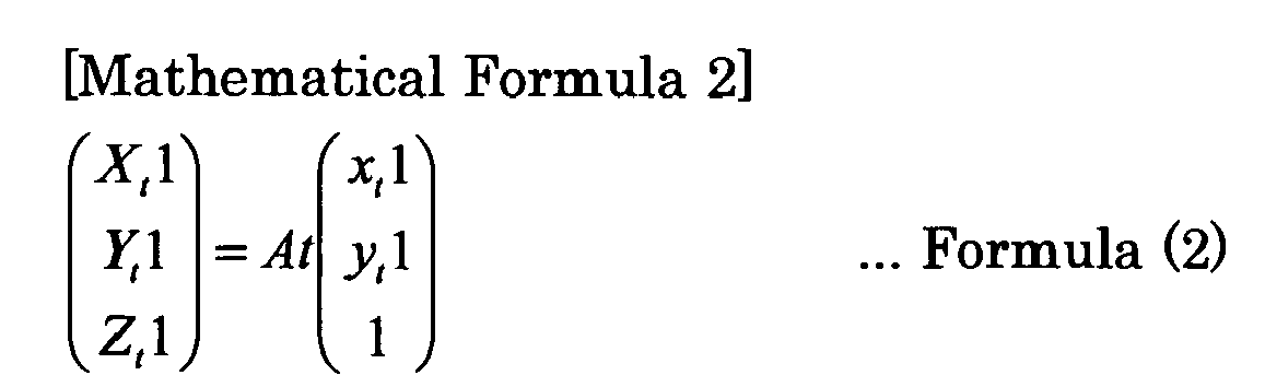
In the formula, At is a 3x3 conversion matrix, and can be acquired in advance by means of preprocessing such as calibration. That is, At is a known parameter.
Here, planes perpendicular to the optical-axis direction of theimage pickup element 300 are represented by an Xt-axis and a Yt-axis, and the orientation (image pickup direction) of theimage pickup element 300 is represented by a Zt-axis. In such a coordinate space, it should be noted that an inclination (vector) of the orientation (image pickup direction) of theimage pickup element 300 is known. - (2) The
computation unit 250 computes a formula of a straight line Lv connecting thecrossing point P s1 and thecrossing point P u1 with each other. Similarly, thecomputation unit 250 computes a formula of a straight line Lw connecting thecrossing point P t1 and thecrossing point P u1 with each other. The formulas of the straight line Lv and the straight line Lw are represented as follows.
In the formulas, Ks and Kt are parameters. - (3) The
computation unit 250 converts the straight line Lw to the straight line Lw' in the three-dimensional space in which the focal point Os of theprojection display apparatus 100 is defined as an origin. The straight line lw, is represented by the formula below.
In the formula, the optical axis of theprojection display apparatus 100 and the orientation (image pickup direction) of theimage pickup element 300 are known; and therefore, a parameter R indicating a rotational component is known. Similarly, since relative positions of theprojection display apparatus 100 and theimage pickup element 300 are known, a parameter T indicating a translational component is also known. - (4) The
computation unit 250 computes parameters Ks and Kt at a crossing point (i.e., crossing point Pu1) of the straight line Lv and the straight line Lw', based upon formula (3) and formula (5). Subsequently, thecomputation unit 250 computes the coordinate values of the coordinate (X u1,Y u1, Zu1) of thecrossing point P u1, based upon the coordinate (X s1,Y s1, Zs1) of thecrossing point P s1 and the parameter Ks. Alternatively, thecomputation unit 250 computes the coordinate values of the coordinate (X u1,Y u1, Zu1) of thecrossing point P u1, based upon the coordinate (X t1,Y t1, Zt1) of thecrossing point P t1 and Kt.
In this manner, thecomputation unit 250 computes the coordinates (X u1,Y u1, Zu1) of thecrossing point P u1. Similarly, thecomputation unit 250 computes the coordinates (X u2,Y u2, Zu2) of thecrossing point P u2, the coordinates (X u3,Y u3, Zu3) of thecrossing point P u3, and the coordinates (X u4,Y u4, Zu4) of thecrossing point P u4.
Second, thecomputation unit 250 computes a vector of the normal line M of theprojection plane 400. Specifically, thecomputation unit 250 computes a vector of the normal line M of theprojection plane 400 by employing the coordinates of at least three crossing points, ofcrossing point P u1 tocrossing point P u4. The formula of theprojection plane 400 is represented as follows, where parameters k1, k2, k3 represents vectors of the normal line M of theprojection plane 400.
- In the formula, k1, k2, k3, k4 are predetermined coefficients.
- In this manner, the
computation unit 250 can compute a shift length between the optical axis N of theprojection display apparatus 100 and the normal line M of theprojection plane 400. That is, thecomputation unit 250 can compute a positional relationship between theprojection display apparatus 100 and theprojection plane 400. - While the first embodiment described the specifying
unit 240 and thecomputation unit 250 separately, the specifyingunit 240 and thecomputation unit 250 may be considered as one constituent element. For example, thecomputation unit 250 may have the function of the specifyingunit 240. - Turning to
Fig. 3 , theelement control unit 260 converts an image input signal to an image output signal and then controls aliquid crystal panel 50, based upon the converted image output signal. In addition, theelement control unit 260 has its own function shown below. - Specifically, the
element control unit 260 has a (shape adjustment) function of performing automatic correction of the shape of an image projected on theprojection plane 400, based upon a positional relationship between theprojection display apparatus 100 and theprojection plane 400. That is, theelement control unit 260 has a function of automatically performing trapezoidal correction, based upon a positional relationship between theprojection display apparatus 100 and theprojection plane 400. - The projection
unit adjustment unit 270 controls a lens group provided in theprojection unit 110. First, the projectionunit adjustment unit 270 includes the projection-enablerange 410 in thedisplay frame 420 provided on theprojection plane 400, by shifting the lens group provided in the projection unit 110 (zoom adjustment). Specifically, the projectionunit adjustment unit 270 controls the lens group provided in theprojection unit 110 so that the projection-enablerange 410 is included in thedisplay frame 420, based upon a pickup image of a frame detection pattern image acquired by theacquisition unit 230. - Second, the projection
unit adjustment unit 270 adjusts a focus of an image projected on theprojection plane 400, by shifting the lens group provided in the projection unit 110 (focus adjustment). Specifically, the projectionunit adjustment unit 270 controls the lens group provided in theprojection unit 110 so that a focus value of the image projected on theprojection plane 400 is at its maximum value, based upon the pickup image of a focus adjustment image acquired by theacquisition unit 230. - The
element control unit 260 and the projectionunit adjustment unit 270 configure anadjustment unit 280 for adjusting an image projected on theprojection plane 400. - In the first embodiment, the
projection display apparatus 100 projects the frame detection pattern image on theprojection plane 400 to thereby detect thedisplay frame 420 provided on theprojection plane 400. Subsequently, theprojection display apparatus 100 projects the focus adjustment image on theprojection plane 400 and then adjusts a focus of the image projected on theprojection plane 400 for the entirety of the image (test pattern image) projected on theprojection plane 400. Subsequently, theprojection display apparatus 100 projects the test pattern image on theprojection plane 400 and then computes a positional relationship between theprojection display apparatus 100 and theprojection plane 400. Subsequently, theprojection display apparatus 100 adjusts the shape of the image projected on theprojection plane 400, based upon the positional relationship between theprojection display apparatus 100 and theprojection plane 400. - In the first embodiment, the
projection display apparatus 100 specifies line segments included in the test pattern image for the entirety of the test pattern image and then computes the positional relationship between theprojection display apparatus 100 and the projection plane 400 (batch processing mode (first processing mode)). That is, in the batch processing mode, theimage pickup element 300 picks up the entirety of the test pattern image while a focus is adjusted for the entirety of the projection-enablerange 410, and then, theprojection display apparatus 100 specifies three or more line segments included in the test pattern, based upon the pickup image of the entirety of the test pattern image. - Hereinafter, an operation of a projection display apparatus (control unit) according to the first embodiment will be described with reference to the drawings.
Fig. 11 andFig. 12 are flowcharts showing an operation of a projection display apparatus 100 (control unit 200) according to the first embodiment. - As shown in
Fig. 11 , instep 50, theprojection display apparatus 100 performs image adjustment resetting processing. Specifically, theprojection display apparatus 100 resets parameters for shape adjustment, zoom adjustment, or focus adjustment and the like (for example, preset parameters) to initial parameters. - It is preferable that, in image adjustment resetting processing, the
projection display apparatus 100 does not display an image on theprojection plane 400, from the start of the flowchart shown inFig. 11 until image adjustment resetting processing (resetting of various parameters) is performed, in order to disallow a user to visually recognize a change in the shape of an image on theprojection plane 400. - In
step 100, theprojection display apparatus 100 displays (projects) a frame detection pattern image on theprojection plane 400. The frame detection pattern image is a white image or the like, for example. - In
step 200, theimage pickup element 300 provided in theprojection display apparatus 100 picks up an image on theprojection plane 400. That is, theimage pickup element 300 picks up the frame detection pattern image projected on theprojection plane 400. Subsequently, theprojection display apparatus 100 detects adisplay frame 420 provided on theprojection plane 400, based upon the pickup image of the frame detection pattern image. - In step 310, the
projection display apparatus 100 specifies line segments included in the test pattern image for the entirety of the test pattern image and then computes a positional relationship between theprojection display apparatus 100 and the projection plane 400 (batch processing mode). A detailed description of the batch processing mode will be given later (seeFig. 12 ). - In
step 400, theprojection display apparatus 100 adjusts the shape of the image projected on theprojection plane 400, based upon a positional relationship between theprojection display apparatus 100 and the projection plane 400(trapezoidal correction). - As shown in
Fig. 12 , in step S311, theprojection display apparatus 100 displays (projects) a focus adjustment image on theprojection plane 400. The focus adjustment image is an image or the like on which white stripes and black stripes are alternately disposed, for example. - In step 312, the
image pickup element 300 provided in theprojection display apparatus 100 picks up an image on theprojection plane 400. That is, theimage pickup element 300 picks up the focus adjustment image projected on theprojection plane 400. - In step 313, the
projection display apparatus 100 computes a focus value of the focus adjustment image that is projected on theprojection plane 400. - In step 314, the
projection display apparatus 100 determines whether or not the focus value of the focus adjustment image is at its maximum value, for the entirety of the focus adjustment image. Theprojection display apparatus 100 migrates to the processing of step 316 in a case where the focus value is at its maximum value. Theprojection apparatus 100 migrates to the processing ofstep 315 in a case where the focus value is not at its maximum value. - In
step 315, theprojection display apparatus 100 adjusts a focus of the focus adjustment image projected on theprojection plane 400 for the entirety of the projection-enablerange 410. Specifically, theprojection display apparatus 100 shifts the lens group provided in theprojection unit 110, based upon the pickup image of the focus adjustment image. - That is, the
projection display apparatus 100 adjusts a focus of the focus adjustment image so that the focus value is at its maximum value for the entirety of the focus adjustment image, in accordance with loop processing of step 312 to step 315. - In step 316, the
projection display apparatus 100 displays (projects) a test pattern image on theprojection plane 400. - In step 317, the
image pickup element 300 provided in theprojection display apparatus 100 picks up an image on theprojection plane 400. That is, theimage pickup element 300 picks up the test pattern image projected on theprojection plane 400. - In step 318, the
projection display apparatus 100 specifies four line segments (L t1 to Lt4) included in the pickup test pattern image, for the entirety of the pickup test pattern image. - In
step 319, theprojection display apparatus 100 specifies four crossing points (P t1 to Pt4) included in the pickup test pattern image, based upon four line segments (L t1 to Lt4). - In step 320, the
projection display apparatus 100 computes a positional relationship between theprojection display apparatus 100 and theprojection plane 400, based upon the four crossing points (P s1 to Ps4) included in the storage test pattern image and the four crossing points (P t1 to Pt4) included in the pickup test pattern image. - In the first embodiment, three or more line segments included in the test pattern image have an inclination relative to a predetermined line. First, the number of pixels to be sampled to perform edge detection or the like can be reduced in comparison a case in which the line segments included in the test pattern image are taken along the predetermined line. Therefore, a processing burden on image adjustment can be reduced. Second, detection precision of the line segments included in the test pattern image is improved in comparison with a case in which the line segments included in the test pattern image are taken along the predetermined line.
- Hereinafter,
exemplary modification 1 of the first embodiment will be described with reference to the drawings. Hereinafter, differences from the first embodiment will be mainly described. - Specifically, in the first embodiment, the
projection display apparatus 100 specifies line segments included in a test pattern image, for the entirety of the test pattern image, and then, computes a positional relationship between theprojection display apparatus 100 and the projection plane 400 (batch processing mode). - In contrast to this, in
exemplary modification 1, theprojection display apparatus 100 specifies line segments included in a test pattern image, for a respective one of a plurality of image regions divided so as to partially include the test pattern image, and then, computes a positional relationship between theprojection display apparatus 100 and the projection plane 400 (divisional processing mode (second processing mode)). That is, in the divisional processing mode, theimage pickup element 300 picks up a test pattern image in a respective one of a plurality of image regions, in a state in which a focus is adjusted by the plurality of image regions, and then, theprojection display apparatus 100 specifies three or more line segments included in the test pattern image, based upon a pickup image of the test pattern image in the plurality of image regions. - Specifically, as shown in
Fig. 13 , the projection-enablerange 410 includes a plurality of image regions (for example,image region # 1 to image region #4). These image regions each are divided so as to partially include a test pattern image. - Here, the
projection display apparatus 100, as shown inFig. 14(a) , displays a focus adjustment image in theimage region # 1, and then, adjusts a focus of the focus adjustment image displayed in theimage region # 1, for theimage region # 1. Subsequently, theprojection display apparatus 100 specifies line segments included in a pickup image as a part of the test pattern image, based upon a pickup image as a part of the test pattern image displayed in theimage region # 1 in which a focus is adjusted. - Similarly, the
projection display apparatus 100, as shown inFig.14(b) to Fig. 14(d) , sequentially displays focus adjustment images in theimage region # 2 to theimage region # 4, and then, adjusts a focus of the focus adjustment image displayed in a respective one of theimage region # 2 to theimage region # 4, for the respective one of theimage region # 2 to theimage region # 4. Subsequently, theprojection display apparatus 100 sequentially specifies the line segments included in a part of the test pattern image, based upon the pickup image as a part of the test pattern images displayed in theimage region # 2 to theimage region # 4 in which a focus is adjusted. - Hereinafter, an operation of a projection display apparatus (control unit) according to
exemplary modification 1 will be described with reference to the drawings.Fig. 15 andFig. 16 are flowcharts showing an operation of the projection display apparatus 100 (control unit 200) according toexemplary modification 1. InFig. 15 , like processing steps shown inFig. 11 are designated by like reference numerals. Therefore, a description of the processing shown instep 100,step 200, and step 400 is omitted here. - As shown in
Fig. 15 , instep 350, theprojection display apparatus 100 specifies line segments included in a test pattern image, for a respective one of a plurality of image regions divided so as to partially include the test pattern image, and then, computes a positional relationship between theprojection display apparatus 100 and the projection plane 400 (divisional processing mode). A detailed description of the divisional processing mode will be given with reference toFig. 16 . - As shown in
Fig. 16 , in step S351, theprojection display apparatus 100 sets a target region in which line segments are to be specified, from among a plurality of image regions divided so as to partially include the test pattern image. For example, theprojection display apparatus 100 sets theimage region # 1 as a target region. - In step 352A, the
projection display apparatus 100 displays (projects) a focus adjustment image on theprojection plane 400, for the target region. The focus adjustment image is an image or the like on which white stripes and black stripes are alternately disposed, for example. - In step 353A, the
image pickup element 300 provided in theprojection display apparatus 100 picks up an image on theprojection plane 400. That is, theimage pickup element 300 picks up the focus adjustment image projected at a position corresponding to the target region (for example, image region #1). - In step 354A, the
projection display apparatus 100 computes a focus value of the focus adjustment image projected at the position corresponding to the target region (for example, image region #1). - In step 355A, the
projection display apparatus 100 determines whether or not the focus value of the focus adjustment image projected at the position corresponding to the target region (for example, image region #1) is at its maximum value. Theprojection display apparatus 100 migrates to the processing of step 357, in a case where the focus value is at its maximum value. Theprojection display apparatus 100 migrates to the processing of step 356A, in a case where the focus value is not at its maximum value. - In step 356A, the
projection display apparatus 100 adjusts a focus of the focus adjustment image projected in the target region, for the target region (for example, image region #1). Specifically, theprojection display apparatus 100 shifts the lens group provided in theprojection unit 110, based upon the pickup image of the focus adjustment image. - That is, the
projection display apparatus 100 adjusts the focus of the focus adjustment image projected in the target region so that the focus value is at its maximum value for the target region (for example, image region #1), by means of loop processing of step 353A to step 356A. - In step 357, the
projection display apparatus 100 displays (projects) a test pattern image on theprojection plane 400. - In
step 358, theimage pickup element 300 provided in theprojection display apparatus 100 picks up an image on theprojection plane 400. That is, theimage pickup element 300 picks up the test pattern image projected at the position corresponding to the target region (for example, image region #1). - In step 359, the
projection display apparatus 100 specifies four line segments (at least one ofL t1 to Lt4) included in a part of the pickup test pattern image corresponding to the target region, based upon a part of the pickup test pattern image corresponding to the target region (for example, image region #1). - In step 360, the
projection display apparatus 100 determines whether or not all of the plurality of image regions configured to partially include the test pattern image are set as target regions. - In step 361, the
projection display apparatus 100 specifies four line segments (L t1 to Lt4) included in a pickup test pattern image, by employing the line segments specified in a respective one of a plurality of image regions configured so as to partially include the test pattern image. Subsequently, theprojection display apparatus 100 specifies four crossing points (P t1 to Pt4) included in the pickup test pattern image. - In
step 362, theprojection display apparatus 100 computes a positional relationship between theprojection display apparatus 100 and theprojection plane 400, based upon four crossing points (P s1 to Ps4) included in the storage test pattern image and four crossing points (P t1 to Pt4) included in the pickup test pattern image. - According to
exemplary modification 1, in the divisional processing mode, theimage pickup element 300 picks up a test pattern image in a respective one of a plurality of image regions in a state in which a focus is adjusted by the plurality of image regions; and theprojection display apparatus 100 specifies three or more line segments included in the test pattern image, based upon the pickup image of the test pattern image in a respective one of a plurality of image regions. - Therefore, in a case in which an optical axis of the
projection display apparatus 100 is extremely inclined relative to a normal line of theprojection plane 400, even if a focus cannot be adjusted for the entirety of the test pattern image, the precision of specifying three or more line segments included in the test pattern image is improved. - In a case where a focus cannot be adjusted for the entirety of the test pattern image, it should be noted that: the precision of edge detection or the like lowers; and the precision of specifying three or more line segments included in the test pattern image is low.
- Hereinafter,
exemplary modification 2 of the first embodiment will be described with reference to the drawings. Hereinafter, differences fromexemplary modification 1 will be mainly described. - Specifically, according to
exemplary modification 1, in a divisional processing mode, theimage pickup element 300 picks up a test pattern image in a respective one of a plurality of regions in a state in which a focus is adjusted in a respective one of the plurality of image regions, and theprojection display apparatus 100 specifies three or more line segments included in the test pattern image, based upon the pickup image of the test pattern image in a respective one of the plurality of image regions. - In contrast to this, according to
exemplary modification 2, theimage pickup element 300 picks up a test pattern image in a respective one of a plurality of image regions in a state in which exposure condition is adjusted by the plurality of image regions, and then, theprojection display apparatus 100 specifies three or more line segments including the test pattern image, based upon the pickup image of the test pattern image in a respective one of the plurality of image regions. - Hereinafter, a control unit according to
exemplary modification 2 will be described with reference to the drawings.Fig. 17 is a block diagram depicting acontrol unit 200 according toexemplary modification 2. InFig. 17 , like constituent elements shown inFig. 3 are designated by like reference numerals. - As shown in
Fig. 17 , thecontrol unit 200 has anexposure control unit 290 in addition to the constituent elements shown inFig. 3 . - The
exposure control unit 290 adjusts exposure condition of theimage pickup element 300, based upon a pickup image of an exposure adjustment image. Specifically, theexposure control unit 290 adjusts the exposure condition of theimage pickup element 300 for a respective one of a plurality of image regions divided so as to partially include a test pattern image. For example, the exposure condition is an exposure time of theimage pickup element 300. The exposure condition may include a setting value of a gain of theimage pickup element 300. - According to
exemplary modification 2, as shown inFig. 18 , the projection-enablerange 410 includes a plurality of image regions (for example,image region # 1 to image region #4), likeexemplary modification 1. The image regions each are divided so as to partially include the test pattern image. - Here, the
projection display apparatus 100, as shown inFig. 19(a) , displays an exposure adjustment image and then adjusts the exposure condition of theimage pickup element 300 for theimage region # 1. Subsequently, theprojection display apparatus 100 specifies line segments included in a pickup image as a part of the test pattern image, based upon the pickup image as a part of the test pattern image displayed in theimage region # 1 in which exposure condition is adjusted. - Similarly, the
projection display apparatus 100, as shown inFig.19(b) to Fig. 19(b) , sequentially displays exposure adjustment images and then adjusts the exposure condition of theimage pickup element 300 for a respective one of theimage region # 2 to theimage region # 4. Subsequently, theprojection display apparatus 100 sequentially specifies the line segments included in a part of the test pattern image, based upon the pickup image as a part of the test pattern image displayed in theimage region # 2 to theimage region # 4 in which exposure condition is adjusted. - Hereinafter, an operation of the projection display apparatus (control unit) according to
exemplary modification 2 will be described with reference to the drawings.Fig. 20 is a flowchart illustrating an operation of the projection display apparatus 100 (control unit 200) according toexemplary modification 2.Fig. 20 is a flowchart illustrating a divisional processing mode. InFig. 20 , like processing steps shown inFig. 16 are designated by like reference numerals. Therefore, a description of the processing of step 351 and step 357 to step 362 is omitted here. - As shown in
Fig. 20 , in step 352B, theprojection display apparatus 100 displays (projects) an exposure adjustment image. The exposure adjustment image is a white image or the like, for example. - In step 353B, the
image pickup element 300 provided in theprojection display apparatus 100 picks up an image on theprojection plane 400. That is, theimage pickup element 300 picks up at least the exposure adjustment image projected at a position corresponding to a target region (for example, image region #1). - In step 354B, the
projection display apparatus 100 computes an exposure value of the exposure adjustment image projected at the position corresponding to the target region (for example, image region #1). - In step 355B, the
projection display apparatus 100 determines whether or not the exposure value of the exposure adjustment image projected at the position corresponding to the target region (for example, image region #1) is at its optimal value. Theprojection display apparatus 100 migrates to the processing of step 357 in a case where the exposure value is at its optimal value. Theprojection display apparatus 100 migrates to the processing of step 356 in a case where the exposure value is not at its optimal value. - In step 356B, the
projection display apparatus 100 adjusts exposure condition of theimage pickup element 300 for the target region (for example, image region #1). Specifically, theprojection display apparatus 100 adjusts the exposure condition (for example, shutter speed) of theimage pickup element 300, based upon the pickup image of the exposure adjustment image. - That is, the
projection display apparatus 100 adjusts the exposure condition of the focus adjustment image projected in the target region, so that the exposure value is at its optimal value for the target region (for example, image region #1), by means of the loop processing of step 353B to step 356B. - According to
exemplary modification 2, in the divisional processing mode, theimage pickup element 300 picks up a test pattern image in a respective one of a plurality of image regions in a state in which exposure condition is adjusted by a respective one of a plurality of image regions, and theprojection display apparatus 100 specifies three or more line segments included in the test pattern image, based upon the pickup image of the test pattern image in the plurality of image regions. - Therefore, in a case where the optical axis of the
projection display apparatus 100 is extremely inclined relative to the normal line of theprojection plane 400, even if the brightness of the projection-enablerange 410 is lacking in uniformity, the precision of specifying three or more line segments included in the test pattern image is improved. - In the case where the brightness of the projection-enable
range 410 is lacking in uniformity, it should be noted that: the quality of the image picked up by means of theimage pickup element 300 lowers; and the precision of specifying three or more line segments included in the test pattern image is low. - Hereinafter,
exemplary modification 3 of the first embodiment will be described with reference to the drawings. Hereinafter, differences from the first embodiment will be mainly described. - Specifically, in
exemplary modification 3, theprojection display apparatus 100 performs operation of a divisional processing mode, in a case where a positional relationship between theprojection display apparatus 100 and theprojection plane 400 is outside an allowable range as a result obtained by performing operation of a batch processing mode. - Hereinafter, a control unit according to
exemplary modification 3 will be described with reference to the drawings.Fig. 21 is a block diagram depicting acontrol unit 200 according toexemplary modification 3. InFig. 21 , like constituent elements shown inFig. 3 are designated by like reference numerals. - As shown in
Fig. 21 , thecontrol unit 200 has amode control unit 295 in addition to the constituent elements shown inFig. 3 . - The
mode control unit 295 controls a batch processing mode and a divisional processing mode. Specifically, themode control unit 295 controls theacquisition unit 230, the specifyingunit 240, thecomputation unit 250, and theimage pickup element 300 in accordance with a processing mode. - In detail, the
mode control unit 295 acquires from the computation unit 250 a positional relationship between theprojection display apparatus 100 and theprojection plane 400, the positional relationship having been computed in the batch processing mode. Subsequently, themode control unit 295 determines whether or not the positional relationship is within an allowable range. - In the case where the positional relationship is within the allowable range, the
mode control unit 295 instructs theelement control unit 260 to adjust the shape of an image projected on theprojection plane 400, based upon the positional relationship computed in the batch processing mode. - On the other hand, in the case where the positional relationship is not within the allowable range, the
mode control unit 295 controls theacquisition unit 230, the specifyingunit 240, thecomputation unit 250, the projectionunit adjustment unit 270, and theimage pickup element 300 to perform operation of a divisional processing mode. Subsequently, themode control unit 295 instructs theelement control unit 260 to adjust the shape of the image projected on theprojection plane 400, based upon the positional relationship computed in the divisional processing mode. - Hereinafter, an operation of the projection display apparatus (control unit) according to
exemplary modification 3 will be described with reference to the drawings.Fig. 22 is a flowchart illustrating an operation of the projection display apparatus 100 (control unit 200) according toexemplary modification 3. InFig. 22 , like processing steps shown inFig. 11 are designated by like reference numerals. Therefore, a description of the processing ofstep 100,step 200, and step 400 is omitted here. - Since a detailed description of step 310 is similar to that of
Fig. 12 , a description of the processing of step 310 is omitted here. In addition, since a detailed description ofstep 350 is similar to that ofFig. 16 , a description of the processing of thestep 350 is omitted here. - As shown in
Fig. 22 , theprojection display apparatus 100 determines whether or not a positional relationship between theprojection display apparatus 100 and theprojection plane 400 is within an allowable range as a result obtained by performing operation of the batch processing mode. In the case where the positional relationship is within the allowable range, theprojection display apparatus 100 migrates to the processing ofstep 400 without performing operation of the divisional processing mode. In the case where the positional relationship is not within the allowable range, theprojection display apparatus 100 migrates to the processing ofstep 350. - According to
exemplary modification 3, theprojection display apparatus 100 performs operation of the divisional processing mode in the case where the positional relationship between theprojection display apparatus 100 and theprojection plane 400 is outside the allowable range as a result obtained by performing operation of the batch processing mode. That is, the divisional processing mode is eliminated in a case where there is no need to perform operation of the divisional processing mode. Therefore, an increase in a processing burden of image adjustment can be restrained. - Hereinafter,
exemplary modification 4 of the first embodiment will be described with reference to the drawings. Hereinafter, differences from the first embodiment will be mainly described. -
Fig. 23 is a front view of aprojection display apparatus 100 according toexemplary modification 4. As shown inFig. 23 , theimage pickup element 300 is disposed so that the orientation of a predetermined line in a case where theimage pickup element 300 outputs image pickup data is different from a horizontal direction. - Therefore, as shown in
Fig. 24 , even in a case where a test pattern image is formed in a rectangular shape which is substantially similar to that of the projection-enablerange 410, the four edges of the test pattern image have an inclination relative to the orientation of the predetermined line in a case where theimage pickup element 300 outputs image pickup data. - In this manner, as shown in
Fig. 25 , the point group Pedge having a difference in shading or contrast (edge) is detected with an inclination relative to the orientation of the predetermined line. - While the present invention has been described by way of the foregoing embodiments, it should not be understood that the statements and drawings forming part of this disclosure limits the invention. From this disclosure, a variety of alternate embodiments, examples, and applicable techniques would have been apparent to one skilled in the art.
- The foregoing embodiments illustrated an incandescent light source as a light source. However, the light source may be an LED (Laser Emitting Diode) or an LD (Laser Diode).
- The foregoing embodiments illustrated a transmissive liquid crystal panel as a light valve. However, the light valve may be a reflective liquid crystal panel or a DMD (Digital Micromirror Device).
- Although not set forth in the foregoing embodiments in particular, a divisional processing mode may be a combination of focus adjustment shown in
exemplary modification 1 and exposure condition adjustment shown inexemplary modification 2. -
Exemplary modification 3 illustrated focus adjustment shown inexemplary modification 1 as a divisional processing mode. However, the divisional processing mode of the embodiments is not limitative thereto. Inexemplary modification 3, the exposure condition adjustment shown inexemplary modification 2 may be applied as the divisional processing mode. - Although not set forth in the foregoing embodiments in particular, it is preferable that the
element control unit 260 controls theliquid crystal panel 50 so as not to display an image, until a test pattern image is displayed, after thedisplay frame 420 has been detected. - Although not set forth in the foregoing embodiments in particular, it is preferable that the
element control unit 260 controls theliquid crystal panel 50 so as not to display an image, until the shape of an image projected on theprojection plane 400 is corrected, after three or more crossing points included in a pickup test pattern image have been acquired. - Although not set forth in the foregoing embodiments in particular, it is preferable that the
element control unit 260 controls theliquid crystal panel 50 so as to display a test pattern image and a predetermined image (for example, background image) other than the test pattern image simultaneously. - A test pattern image is comprised of colors and luminance which are detectable by means of the
image pickup element 300, for example, and a predetermined image other than the test pattern image is comprised of colors and luminance which are undetectable by means of theimage pickup element 300. - Alternatively, a test pattern image is comprised of any of red, green, and blue colors, and a predetermine image other than the test pattern image is comprised of other colors. The
image pickup element 300 can acquire a pickup image of a test pattern image by detecting only the colors configuring the test pattern image. - In a case where no image signal is inputted, the
element control unit 260 may controlliquid crystal panel 50 so as to display an error message as a predetermined image together with the test pattern image. Alternatively, in a case where a line segment or a cross point included in a test pattern image cannot be specified, theelement control unit 260 may control theliquid crystal panel 50 so as to display an error message as a predetermined image. - In the embodiments, the
projection display apparatus 100 adjusts a focus after detection of thedisplay frame 420. However, adjustment of the embodiments is not limitative thereto. Theprojection display apparatus 100 may adjust a focus without detecting thedisplay frame 420, for example. Specifically, in an ordinary use mode, since it is presupposed that a central portion of the projection-enablerange 410 is included in thedisplay frame 420, theprojection display apparatus 100 may display a focus adjustment image at the central portion of the projection-enablerange 410 and adjust a focus of an image (focus adjustment image) displayed at the central portion of the projection-enablerange 410. - In the embodiments, a test pattern image is black at its background portion and is white at its pattern portion. However, the test pattern image of the embodiments is not limitative thereto. The image may be white at its background portion and black at its pattern portion, for example. In addition, the pattern may be blue at its background portion and white at its pattern portion. That is, there may be a difference in luminance between its background portion and its pattern portion to an extent of enabling edge detection. The extent of enabling edge detection is determined in accordance with a precision of the
image pickup element 300. The greater the luminance difference between its background portion and its pattern portion is, the less necessary the precision of theimage pickup element 300 is; and therefore, as a matter of course, theimage pickup element 300 can be reduced in cost. - In the foregoing embodiments, the
projection display apparatus 100 perform processing steps from the step of performing focus adjustment (or exposure adjustment) to the step of specifying a line segment, by target region, in a divisional processing mode. However, the apparatus of the embodiments is not limitative thereto. Theprojection display apparatus 100, having performed focus adjustment (or exposure adjustment) on a target-region basis and then stored a focus value (or exposure value) on the target-region basis, may specify a line segment included in each target region while the focus value (or exposure value) is changed on the target-region basis.
Claims (10)
- A projection display apparatus having an imager (50) configured to modulate light emitted from a light source (10) and a projection unit (110) configured to project light emitted from the imager (50) on a projection plane, the apparatus comprising:an element control unit (260) configured to control the imager so as to display a test pattern image configuring at least one portion of a respective one of three or more line segments configuring three or more crossing points;an acquisition unit (230) configured to acquire a pickup image of the test pattern image outputted along a predetermined line from an image pickup element (300) configured to pick up the test pattern image projected on the projection plane;a computation unit (250) configured to specify three or more crossing points from three or more line segments included in the pickup image, based upon the pickup image acquired by the acquisition unit, and to compute a positional relationship between the projection image apparatus and the projection plane, based upon the three or more crossing points; andan adjustment unit (280) configured to adjust an image projected on the projection plane, based upon the positional relationship between the projection display apparatus and the projection plane, whereinthe three or more line segments have an inclination relative to the predetermined line.
- The projection display apparatus according to claim 1, wherein
the predetermined line is a line extending along a horizontal direction. - The projection display apparatus according to claim 1 or 2, wherein
the element control unit (260) controls the imager so as not to display an image, until a shape of an image projected on the projection plane is corrected, after three or more crossing points included in the pickup image are acquired. - The projection display apparatus according to claim 1 or 2, wherein
the element control unit (260) controls the imager so as to display the test pattern image and a predetermined image other than the test pattern image. - The projection display apparatus according to any of claims 1 to 4, wherein
the image pickup element (300) is disposed so that the three or more line segments have an inclination relative to the predetermined line. - The projection display apparatus according to any of claims 1 to 5, wherein
the adjustment unit (280) includes a focus adjustment unit configured to adjust a focus of an image projected on the projection plane,
the focus adjustment unit sequentially adjusts a focus in a respective one of a plurality of image regions divided so as to partially include the test pattern image, and
the computation unit (250) specifies a line segment included in a part of the test pattern image, based upon a pickup image as a part of a test pattern image displayed in an image region in which a focus is adjusted. - The projection display apparatus according to any of claims 1 to 6, further comprising an exposure control unit (290) configured to sequentially adjust an exposure condition of the image pickup element (300) in a respective one of the plurality of image regions divided so as to partially include the test pattern image, wherein
the computation unit (250) specifies the line segment included in a part of the test pattern image, based upon a pickup image as a part of a test pattern image displayed in an image region in which exposure condition is adjusted. - The projection display apparatus according to any of claims 1 to 5, further comprising a mode control unit (295) configured to control a first processing mode and a second processing mode, wherein:the adjustment unit (280) includes a focus adjustment unit configured to adjust a focus of the image projected on the projection plane;the first processing mode is a mode of specifying a line segment included in the test pattern image for an entirety of the test pattern image and computing a positional relationship between the projection display apparatus and the projection plane;the second processing mode is a mode of specifying a line segment included in the test pattern image for a respective one of a plurality of image regions divided so as to partially include the test pattern image and computing a positional relationship between the projection display apparatus and the projection plane; andthe mode control unit (295) performs operation of the second processing mode, in a case where the positional relationship between the projection display apparatus and the projection plane is outside an allowable range, as a result obtained by performing operation of the first processing mode.
- The projection display apparatus according to any of claims 1 to 6, further comprising a mode control unit (295) configured to control a first processing mode and a second processing mode, wherein:the adjustment unit includes an exposure control unit (290) configured to adjust an exposure condition of the image pickup;the first processing mode is a mode of specifying a line segment included in the test pattern image for an entirety of the test pattern image and computing a positional relationship between the projection display apparatus and the projection plane;the second processing mode is a mode of specifying a line segment included in the test pattern image for a respective one of a plurality of image regions divided so as to partially include the test pattern image and computing a positional relationship between the projection display apparatus and the projection plane; andthe mode control unit (295) performs operation of the second processing mode, in a case where the positional relationship between the projection display apparatus and the projection plane is outside an allowable range, as a result obtained by performing operation of the first processing mode.
- An image adjustment method applied to a projection display apparatus having an imager (50) configured to modulate light emitted from a light source (10), and a projection unit (110) configured to project light emitted from the imager (50) on a projection plane, the method comprising:step A of displaying a test pattern image configuring at least one portion of a respective one of three or more line segments configuring three or more crossing points;step B of picking up the test pattern image projected on the projection plane, and acquiring a pickup image of the test pattern image along a predetermined line having an inclination relative to the three or more line segments;step C of computing a positional relationship between the projection display apparatus and the projection plane, based upon the pickup image; andstep D of adjusting an image projected on the projection plane, based upon the positional relationship between the projection display apparatus and the projection plane.
Applications Claiming Priority (2)
| Application Number | Priority Date | Filing Date | Title |
|---|---|---|---|
| JP2009179774 | 2009-07-31 | ||
| JP2010118460A JP5736535B2 (en) | 2009-07-31 | 2010-05-24 | Projection-type image display device and image adjustment method |
Publications (1)
| Publication Number | Publication Date |
|---|---|
| EP2282547A2 true EP2282547A2 (en) | 2011-02-09 |
Family
ID=42638474
Family Applications (1)
| Application Number | Title | Priority Date | Filing Date |
|---|---|---|---|
| EP10008026A Withdrawn EP2282547A2 (en) | 2009-07-31 | 2010-08-02 | Projection display apparatus and image adjustment method |
Country Status (4)
| Country | Link |
|---|---|
| US (1) | US20110025988A1 (en) |
| EP (1) | EP2282547A2 (en) |
| JP (1) | JP5736535B2 (en) |
| CN (1) | CN101990078A (en) |
Families Citing this family (16)
| Publication number | Priority date | Publication date | Assignee | Title |
|---|---|---|---|---|
| JP2012078658A (en) * | 2010-10-04 | 2012-04-19 | Sanyo Electric Co Ltd | Projection type video display device |
| TWI473497B (en) * | 2011-05-18 | 2015-02-11 | Chip Goal Electronics Corp | Object tracking apparatus, interactive image display system using object tracking apparatus, and methods thereof |
| CN102821285A (en) * | 2012-07-06 | 2012-12-12 | 中影数字巨幕(北京)有限公司 | Digital film playing method and digital film playing system as well as digital film optimizing device |
| JP6056290B2 (en) * | 2012-09-11 | 2017-01-11 | セイコーエプソン株式会社 | Image processing apparatus, projector, and image processing method |
| JP6237018B2 (en) * | 2013-09-11 | 2017-11-29 | セイコーエプソン株式会社 | Projector and control method thereof |
| JP6217110B2 (en) * | 2013-03-29 | 2017-10-25 | セイコーエプソン株式会社 | Projector and adjustment method |
| JP2015132747A (en) * | 2014-01-15 | 2015-07-23 | セイコーエプソン株式会社 | projector |
| CN105744243B (en) * | 2016-01-21 | 2017-08-29 | 上海应用技术学院 | Based on full-automatic geometric correction method in the multi-projection system for cutting the realization of intersection point feature |
| CN109587457A (en) * | 2017-09-29 | 2019-04-05 | 中强光电股份有限公司 | Optical projection system and its automatic setting method |
| JP6642610B2 (en) * | 2018-03-22 | 2020-02-05 | カシオ計算機株式会社 | Projection control device, projection device, projection control method, and program |
| CN110784690B (en) | 2018-07-30 | 2022-05-10 | 中强光电股份有限公司 | Projection system and projection method |
| CN111510694A (en) * | 2019-01-30 | 2020-08-07 | 中强光电股份有限公司 | Projection device and method for generating calibration grid line |
| CN111458964B (en) * | 2020-04-26 | 2022-02-08 | 青岛海信激光显示股份有限公司 | A laser projection device |
| CN114577148B (en) * | 2022-03-25 | 2025-07-15 | 深圳市兴华炜科技有限公司 | Real-time focusing method and device for testing the flatness of thin sheets under high-resolution lens |
| CN115190281B (en) * | 2022-06-30 | 2024-01-02 | 海宁奕斯伟集成电路设计有限公司 | Device and method for adjusting projection position of projector |
| US12504325B2 (en) * | 2023-06-20 | 2025-12-23 | Chroma Ate Inc. | Automated optical measurement system and method for near eye display |
Citations (1)
| Publication number | Priority date | Publication date | Assignee | Title |
|---|---|---|---|---|
| JP2005318652A (en) | 2002-07-23 | 2005-11-10 | Nec Viewtechnology Ltd | Projector with distortion correcting function |
Family Cites Families (14)
| Publication number | Priority date | Publication date | Assignee | Title |
|---|---|---|---|---|
| JP2001346132A (en) * | 2000-03-31 | 2001-12-14 | Ricoh Co Ltd | Image conversion device, image conversion server, image conversion system, image projection device, image projection system, image conversion method, image projection method, and computer-readable recording medium storing a program for causing a computer to execute those methods |
| CN1693984A (en) * | 2002-07-23 | 2005-11-09 | 日本电气视象技术株式会社 | projector |
| EP1385335B1 (en) * | 2002-07-23 | 2009-04-22 | NEC Display Solutions, Ltd. | Image projector with image-feedback control |
| JP2004260785A (en) * | 2002-07-23 | 2004-09-16 | Nec Viewtechnology Ltd | Projector with distortion correction function |
| JP3882927B2 (en) * | 2004-03-29 | 2007-02-21 | セイコーエプソン株式会社 | Image processing system, projector, and image processing method |
| US7517089B2 (en) * | 2004-03-29 | 2009-04-14 | Seiko Epson Corporation | Image processing system, projector, information storage medium, and image processing method |
| JP3960390B2 (en) * | 2004-05-31 | 2007-08-15 | Necディスプレイソリューションズ株式会社 | Projector with trapezoidal distortion correction device |
| JP2006121240A (en) * | 2004-10-20 | 2006-05-11 | Sharp Corp | Image projection method, projector, and computer program |
| JP4114683B2 (en) * | 2005-08-01 | 2008-07-09 | セイコーエプソン株式会社 | How to adjust the position of the projected image |
| US20070030452A1 (en) * | 2005-08-08 | 2007-02-08 | N-Lighten Technologies | Image adaptation system and method |
| WO2007072695A1 (en) * | 2005-12-22 | 2007-06-28 | Matsushita Electric Industrial Co., Ltd. | Image projection device |
| JP2008217267A (en) * | 2007-03-01 | 2008-09-18 | Denso Corp | Road shape recognition device |
| US8128237B2 (en) * | 2007-07-27 | 2012-03-06 | Hewlett-Packard Development Company, L.P. | Plurality of self-activating display shaping devices defining a display area |
| JP2011138019A (en) * | 2009-12-28 | 2011-07-14 | Sanyo Electric Co Ltd | Projection type video display device and image adjusting method |
-
2010
- 2010-05-24 JP JP2010118460A patent/JP5736535B2/en active Active
- 2010-07-30 US US12/847,914 patent/US20110025988A1/en not_active Abandoned
- 2010-08-02 EP EP10008026A patent/EP2282547A2/en not_active Withdrawn
- 2010-08-02 CN CN2010102437359A patent/CN101990078A/en active Pending
Patent Citations (1)
| Publication number | Priority date | Publication date | Assignee | Title |
|---|---|---|---|---|
| JP2005318652A (en) | 2002-07-23 | 2005-11-10 | Nec Viewtechnology Ltd | Projector with distortion correcting function |
Also Published As
| Publication number | Publication date |
|---|---|
| CN101990078A (en) | 2011-03-23 |
| US20110025988A1 (en) | 2011-02-03 |
| JP5736535B2 (en) | 2015-06-17 |
| JP2011050036A (en) | 2011-03-10 |
Similar Documents
| Publication | Publication Date | Title |
|---|---|---|
| US20110025988A1 (en) | Projection display apparatus and image adjustment method | |
| US9075296B2 (en) | Projection display device | |
| US9621861B2 (en) | Projection image display system, projection image display method, and projection-type display apparatus | |
| US9664376B2 (en) | Projection-type image display apparatus | |
| CN105204276B (en) | Optical projection system and projecting apparatus | |
| JP5372857B2 (en) | Projection display device | |
| US20160307483A1 (en) | Image display apparatus and image display method | |
| US20120206696A1 (en) | Projection display apparatus and image adjusting method | |
| US20120140189A1 (en) | Projection Display Apparatus | |
| US20120081678A1 (en) | Projection display apparatus and image adjustment method | |
| US20110175940A1 (en) | Projection display apparatus and image adjustment method | |
| JPWO2016121379A1 (en) | Lens device and image projection device | |
| JPWO2010116837A1 (en) | Multi-projection display system and screen forming method | |
| JP2012165091A (en) | Multi-projection system and projector | |
| US12625421B2 (en) | Projector having a modulated light reduction relay lens system and a control unit correcting white balance based on F-number | |
| JP2012018214A (en) | Projection type video display device | |
| US20120057138A1 (en) | Projection display apparatus | |
| JP2011164246A (en) | Detection device of amount of projection position deviation, detection method of amount of projection position deviation, and projection system | |
| JP6119126B2 (en) | Correction control apparatus, correction method, and projector | |
| JP6418265B2 (en) | Correction control apparatus, correction method, and projector | |
| JP5605473B2 (en) | Projection display device | |
| JP2011138019A (en) | Projection type video display device and image adjusting method | |
| JP2013098712A (en) | Projection type video display device and image adjustment method | |
| JP2011176637A (en) | Projection type video display apparatus | |
| JP2005039655A (en) | Projection type video display apparatus and adjustment method of the display apparatus at shipment |
Legal Events
| Date | Code | Title | Description |
|---|---|---|---|
| PUAI | Public reference made under article 153(3) epc to a published international application that has entered the european phase |
Free format text: ORIGINAL CODE: 0009012 |
|
| AK | Designated contracting states |
Kind code of ref document: A2 Designated state(s): AL AT BE BG CH CY CZ DE DK EE ES FI FR GB GR HR HU IE IS IT LI LT LU LV MC MK MT NL NO PL PT RO SE SI SK SM TR |
|
| AX | Request for extension of the european patent |
Extension state: BA ME RS |
|
| STAA | Information on the status of an ep patent application or granted ep patent |
Free format text: STATUS: THE APPLICATION HAS BEEN WITHDRAWN |
|
| 18W | Application withdrawn |
Effective date: 20140420 |