EP2282437A1 - Method and apparatus for PDCCH allocation in wireless communication system - Google Patents
Method and apparatus for PDCCH allocation in wireless communication system Download PDFInfo
- Publication number
- EP2282437A1 EP2282437A1 EP10008058A EP10008058A EP2282437A1 EP 2282437 A1 EP2282437 A1 EP 2282437A1 EP 10008058 A EP10008058 A EP 10008058A EP 10008058 A EP10008058 A EP 10008058A EP 2282437 A1 EP2282437 A1 EP 2282437A1
- Authority
- EP
- European Patent Office
- Prior art keywords
- carrier
- pdcch
- wireless communication
- communication system
- communication device
- Prior art date
- Legal status (The legal status is an assumption and is not a legal conclusion. Google has not performed a legal analysis and makes no representation as to the accuracy of the status listed.)
- Granted
Links
Images

Classifications
-
- H—ELECTRICITY
- H04—ELECTRIC COMMUNICATION TECHNIQUE
- H04W—WIRELESS COMMUNICATION NETWORKS
- H04W72/00—Local resource management
- H04W72/20—Control channels or signalling for resource management
- H04W72/23—Control channels or signalling for resource management in the downlink direction of a wireless link, i.e. towards a terminal
- H04W72/231—Control channels or signalling for resource management in the downlink direction of a wireless link, i.e. towards a terminal the control data signalling from the layers above the physical layer, e.g. RRC or MAC-CE signalling
-
- H—ELECTRICITY
- H04—ELECTRIC COMMUNICATION TECHNIQUE
- H04L—TRANSMISSION OF DIGITAL INFORMATION, e.g. TELEGRAPHIC COMMUNICATION
- H04L5/00—Arrangements affording multiple use of the transmission path
- H04L5/0001—Arrangements for dividing the transmission path
- H04L5/0003—Two-dimensional division
- H04L5/0005—Time-frequency
- H04L5/0007—Time-frequency the frequencies being orthogonal, e.g. OFDM(A) or DMT
- H04L5/001—Time-frequency the frequencies being orthogonal, e.g. OFDM(A) or DMT the frequencies being arranged in component carriers
-
- H—ELECTRICITY
- H04—ELECTRIC COMMUNICATION TECHNIQUE
- H04L—TRANSMISSION OF DIGITAL INFORMATION, e.g. TELEGRAPHIC COMMUNICATION
- H04L5/00—Arrangements affording multiple use of the transmission path
- H04L5/003—Arrangements for allocating sub-channels of the transmission path
- H04L5/0053—Allocation of signalling, i.e. of overhead other than pilot signals
-
- H—ELECTRICITY
- H04—ELECTRIC COMMUNICATION TECHNIQUE
- H04L—TRANSMISSION OF DIGITAL INFORMATION, e.g. TELEGRAPHIC COMMUNICATION
- H04L5/00—Arrangements affording multiple use of the transmission path
- H04L5/0091—Signalling for the administration of the divided path, e.g. signalling of configuration information
- H04L5/0094—Indication of how sub-channels of the path are allocated
-
- H—ELECTRICITY
- H04—ELECTRIC COMMUNICATION TECHNIQUE
- H04W—WIRELESS COMMUNICATION NETWORKS
- H04W72/00—Local resource management
- H04W72/12—Wireless traffic scheduling
- H04W72/1263—Mapping of traffic onto schedule, e.g. scheduled allocation or multiplexing of flows
Definitions
- the present invention relates to a method and apparatus for Physical Downlink Control Channel (PDCCH) allocation in a wireless communication system according to the pre-characterizing clauses of claims 1, 2, 8 and 9.
- PDCCH Physical Downlink Control Channel
- LTE system Long Term Evolution wireless communication system
- MAC Medium Access Control
- RLC Radio Link Control
- LTE-A LTE Advanced
- CA Carrier aggregation
- UE user equipment
- CA uses multiple component carriers to establish multiple links with a network terminal for simultaneously receiving and transmitting on each component carrier, so as to enhance transmission bandwidth and spectrum aggregation.
- the network terminal configures a plurality of carriers to a UE via a radio resource control (RRC) message.
- RRC radio resource control
- the UE receives Physical Downlink Shared Channels (PDSCHs) on a plurality of configured downlink component carriers.
- PDSCHs Physical Downlink Shared Channels
- the prior art further proposes to monitor a Physical Downlink Control Channels (PDCCHs) on other downlink component carriers, for acquiring related scheduling information, i.e. downlink assignment or uplink grant, to perform data reception or transmission.
- PDSCH and PDCCH may be carried on different component carriers. Therefore, within the configured downlink component carriers, part of component carriers may only carry PDSCHs, and not carry PDCCHs; while another part of component carriers simultaneously carry PDSCHs and PDCCHs.
- the UE can acquire the scheduling for all the configured component carriers by merely monitoring PDCCHs on part of the component carriers.
- power consumption or requirements for computing capability can be reduced, because requirements for the computing capability mainly result from different carriers using different encoding methods, and thus the more the monitored component carriers are, the more complex the required blind decoding computing is.
- requirements for computing capability can be reduced by reducing an amount of the monitored component carriers.
- the present invention aims at providing a method and apparatus capable of reducing power consumption and computing complexity.
- the wireless communication system supports a Carrier Aggregation (CA), which enables a user equipment (UE) of the wireless communication system to perform transmission and/or reception through multiple carriers.
- CA Carrier Aggregation
- the method includes steps of configuring a plurality of carriers to a UE via a radio resource control (RRC) message, and including an information for each configured carrier in the RRC message, to indicate a second carrier which carries a PDCCH corresponding to a first carrier, wherein the PDCCH on the second carrier is used to transmit the downlink assignment or uplink grant for the first carrier.
- RRC radio resource control
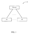
- FIG. 1 illustrates a schematic diagram of a wireless communication system 10.
- the wireless communication system 10 is preferably an LTE advanced (LTE-A) system, and is briefly composed of a network and a plurality of user equipments (UEs).
- LTE-A LTE advanced
- UEs user equipments
- the network and the UEs are simply utilized for illustrating the structure of the wireless communication system 10.
- the network may comprise a plurality of base stations (Node Bs), radio network controllers and so on according to actual demands, and the UEs can be devices such as mobile phones, computer systems, etc.
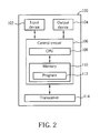
- FIG. 2 is a functional block diagram of a communication device 100 in a wireless communication system.
- the communication device 100 can be utilized for realizing the network or the UEs in FIG.1 .
- FIG. 2 only shows an input device 102, an output device 104, a control circuit 106, a central processing unit (CPU) 108, a memory 110, a program 112, and a transceiver 114 of the communication device 100.
- the control circuit 106 executes the program 112 in the memory 110 through the CPU 108, thereby controlling an operation of the communication device 100.
- the communication device 100 can receive signals input by a user through the input device 102, such as a keyboard, and can output images and sounds through the output device 104, such as a monitor or speakers.
- the transceiver 114 is used to receive and transmit wireless signals, deliver received signals to the control circuit 106, and output signals generated by the control circuit 106 wirelessly. From a perspective of a communication protocol framework, the transceiver 114 can be seen as a portion of Layer 1, and the control circuit 106 can be utilized to realize functions of Layer 2 and Layer 3.
- FIG 3 is a diagram of the program 112 shown in FIG. 2 .
- the program 112 includes an application layer 200, a Layer 3 202, and a Layer 2 206, and is coupled to a Layer 1 218.
- the Layer 3 202 performs radio resource control.
- the Layer 2 206 comprises a Radio Link Control (RLC) layer and a Medium Access Control (MAC) layer, and performs link control.
- the Layer 1 218 performs physical connections.
- RLC Radio Link Control
- MAC Medium Access Control
- the Layer 1 218 and the Layer 2 206 may support a Carrier Aggregation (CA) technology, which enables the UE to perform transmission or reception through multiple carriers configured by the upper layer.
- CA Carrier Aggregation
- the embodiment of the present invention provides a PDCCH allocation program 220 for reducing required power consumption and computing for the UE to monitor PDCCHs.
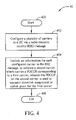
- FIG 4 is a schematic diagram of a process 40 according to an embodiment of the present invention.
- the process 40 is utilized for PDCCH allocation in a network terminal of the wireless communication system 10, and can be compiled into the PDCCH allocation program 220.
- the process 40 includes the following steps:
- the network terminal configures a plurality of carriers to the UE via an RRC message, and the RRC message includes an information for each configured carrier.
- the information indicates a second carrier which carries a PDCCH corresponding to a first carrier, and the PDCCH is used to transmit the downlink assignment or uplink grant for the first carrier information.
- the UE can know which carrier carries the PDCCH corresponding to another carrier according to the information included in the RRC message and monitor the PDCCH correctly, so as to acquire the downlink assignment or the uplink grant for this carrier.
- the downlink assignment or the uplink grant for each carrier is transmitted on a specific PDCCH, and a correlation between a carrier and a PDCCH can be known from the information in the RRC message sent by the network terminal.
- the UE only needs to monitor proper PDCCHs according to an operating status, and thus reduces power consumption and computing required by monitoring carriers. For example, when a transmission fails and a retransmission is performed, since packet for the retransmission is only transmitted on the original carrier, according to the embodiment of the present invention, the UE can know which PDCCH is corresponding to the carrier, and only monitor the PDCCH instead of monitoring all PDCCHs, to reduce power consumption and computing complexity.
- the network terminal configures five carriers CC1 ⁇ CC5 to the UE via the RRC message, and the carriers CC1 ⁇ CC3 simultaneously carry PDSCHs and PDCCHs, and the carriers CC4, CC5 only carry PDSCHs.
- Downlink assignment for the carrier CC4 is transmitted on the PDCCH on the carrier CC2
- downlink assignment of the carrier CC5 is transmitted on the PDCCH on the carrier CC3. Therefore, the carriers CC1 ⁇ CC3 relate to the second carrier of the process 40, while the carriers CC4, CC5 relate to the first carrier.
- the RRC message sent by the network terminal includes information, for indicating the UE a correlation between a carrier and a PDCCH. Therefore, if a transmission failure occurs on the carrier CC4 and a retransmission is performed, the UE only needs to monitor the PDCCH on the carrier CC2 without monitoring the PDCCHs on the carriers CC1 and CC3.
- the above example is for downlink operations, and can be simply modified for uplink operations.
- the first carrier carries a Physical Downlink Shared Channel (PDSCH), and the PDCCH on the second carrier transmits the downlink assignment for the first carrier;
- the first carrier carries a Physical Uplink Shared Channel (PUSCH), and the PDCCH on the second carrier transmits the uplink grant for the first carrier.
- PDSCH Physical Downlink Shared Channel
- PUSCH Physical Uplink Shared Channel
- the RRC message in the process 40 is preferably an RRC Connection Reconfiguration message.
- the first carrier and the second carrier are only utilized for indicating a relation in relative to a PDCCH, and can be identical or different carriers.
- the first carrier refers to a carrier which carries PDSCH or PUSCH
- the second carrier refers to a carrier which carries the PDCCH corresponding to the first carrier. If the first carrier and the second carrier are the same, a PDCCH carried on a carrier is utilized for transmitting downlink assignment or uplink grant for the same carrier.
- the PDCCH can further include a carrier indication (CI) field, for indicating which carrier the downlink assignment or the uplink grant carried by the PDCCH is corresponding to.
- a bit length of the CI field can be 3 bits, or depends on an amount of carriers configured to the UE.
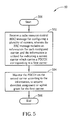
- the above operations related to the UE can further be summarized into a process 50 as shown in FIG 5 .
- the process 50 is utilized for PDCCH allocation in a UE of the wireless communication system 10, and can be compiled into the PDCCH allocation program 220.
- the process 50 includes the following steps:
- the process 50 is derived from the process 40 for implementing operations of the UE, and detailed description and modifications can be referred to the above description, and are not narrated hereinafter.
- the above realization of the steps in the processes 40, 50 should be well known by those skilled in the art.
- the steps of the processes 40, 50 can be compiled as units into the PDCCH allocation program 220 by instructions, parameters, variables, etc. of specific programming languages.
- UE does not need to monitor all PDCCHs, and can reduce power consumption and computing complexity.
Landscapes
- Engineering & Computer Science (AREA)
- Signal Processing (AREA)
- Computer Networks & Wireless Communication (AREA)
- Mobile Radio Communication Systems (AREA)
Abstract
Description
- The present invention relates to a method and apparatus for Physical Downlink Control Channel (PDCCH) allocation in a wireless communication system according to the pre-characterizing clauses of
claims - Long Term Evolution wireless communication system (LTE system), an advanced high-speed wireless communication system established upon the 3G mobile telecommunication system, supports only packet-switched transmission, and tends to implement both Medium Access Control (MAC) layer and Radio Link Control (RLC) layer in one single communication site, such as in base stations (Node Bs) alone rather than in Node Bs and RNC (Radio Network Controller) respectively, so that the system structure becomes simple.
- However, to meet future requirements of all kinds of communication services, the 3rd Generation Partnership Project (3GPP) has started to work out a next generation of the LTE system: the LTE Advanced (LTE-A) system. Carrier aggregation (CA), where two or more component carriers are aggregated, is introduced into the LTE-A system in order to support wider transmission bandwidths, e.g. up to 100MHz and for spectrum aggregation. In the LTE-A system, a user equipment (UE) uses multiple component carriers to establish multiple links with a network terminal for simultaneously receiving and transmitting on each component carrier, so as to enhance transmission bandwidth and spectrum aggregation.
- The network terminal configures a plurality of carriers to a UE via a radio resource control (RRC) message. After CA is configured, the UE receives Physical Downlink Shared Channels (PDSCHs) on a plurality of configured downlink component carriers. Besides, the prior art further proposes to monitor a Physical Downlink Control Channels (PDCCHs) on other downlink component carriers, for acquiring related scheduling information, i.e. downlink assignment or uplink grant, to perform data reception or transmission. In other words, PDSCH and PDCCH may be carried on different component carriers. Therefore, within the configured downlink component carriers, part of component carriers may only carry PDSCHs, and not carry PDCCHs; while another part of component carriers simultaneously carry PDSCHs and PDCCHs. In such a situation, the UE can acquire the scheduling for all the configured component carriers by merely monitoring PDCCHs on part of the component carriers. As a result, power consumption or requirements for computing capability can be reduced, because requirements for the computing capability mainly result from different carriers using different encoding methods, and thus the more the monitored component carriers are, the more complex the required blind decoding computing is. Correspondingly, requirements for computing capability can be reduced by reducing an amount of the monitored component carriers.
- As can be seen from the above, by carrying PDSCHs and PDCCHs on different component carriers and transmitting PDCCHs only on part of component carriers, the amount of the monitored component carriers is reduced, and power consumption or requirements for computing capability can be reduced. However, this method still has some potential for improvement under some circumstances. For example, when a transmission fails and a retransmission is performed, packets for the retransmission are only transmitted on the original carrier. Therefore, in theory, the network terminal only needs to transmit scheduling information required for the retransmission on one PDCCH. However, according to the prior art, the UE still needs to monitor all PDCCHs, since the UE does not know the scheduling information is transmitted on which PDCCH, causing unnecessary power consumption.
- Therefore, how to further reduce power consumption or requirements for computing capability for CA has become an issue in the industry.
- This in mind, the present invention aims at providing a method and apparatus capable of reducing power consumption and computing complexity.
- This is achieved by a method and apparatus for Physical Downlink Control Channel (PDCCH) allocation in a network terminal of a wireless communication system according to the pre-characterizing clauses of
claims - As will be seen more clearly from the detailed description following below, the claimed method for Physical Downlink Control Channel (PDCCH) allocation in a network terminal of a wireless communication system. The wireless communication system supports a Carrier Aggregation (CA), which enables a user equipment (UE) of the wireless communication system to perform transmission and/or reception through multiple carriers. The method includes steps of configuring a plurality of carriers to a UE via a radio resource control (RRC) message, and including an information for each configured carrier in the RRC message, to indicate a second carrier which carries a PDCCH corresponding to a first carrier, wherein the PDCCH on the second carrier is used to transmit the downlink assignment or uplink grant for the first carrier.
- In the following, the invention is further illustrated by way of example, taking reference to the accompanying drawings. Thereof
-
FIG 1 is a schematic diagram of a wireless communications system. -
FIG 2 is a function block diagram of a wireless communications device. -
FIG. 3 is a diagram of a program ofFIG 2 . -
FIG. 4 is a flowchart of a process according to an embodiment of the present invention. -
FIG 5 is a flowchart of another process according to an embodiment of the present invention. - Please refer to
FIG. 1 , which illustrates a schematic diagram of awireless communication system 10. Thewireless communication system 10 is preferably an LTE advanced (LTE-A) system, and is briefly composed of a network and a plurality of user equipments (UEs). InFIG. 1 , the network and the UEs are simply utilized for illustrating the structure of thewireless communication system 10. Practically, the network may comprise a plurality of base stations (Node Bs), radio network controllers and so on according to actual demands, and the UEs can be devices such as mobile phones, computer systems, etc. - Please refer to
FIG 2 , which is a functional block diagram of acommunication device 100 in a wireless communication system. Thecommunication device 100 can be utilized for realizing the network or the UEs inFIG.1 . For the sake of brevity,FIG. 2 only shows aninput device 102, anoutput device 104, a control circuit 106, a central processing unit (CPU) 108, a memory 110, aprogram 112, and atransceiver 114 of thecommunication device 100. In thecommunication device 100, the control circuit 106 executes theprogram 112 in the memory 110 through the CPU 108, thereby controlling an operation of thecommunication device 100. Thecommunication device 100 can receive signals input by a user through theinput device 102, such as a keyboard, and can output images and sounds through theoutput device 104, such as a monitor or speakers. Thetransceiver 114 is used to receive and transmit wireless signals, deliver received signals to the control circuit 106, and output signals generated by the control circuit 106 wirelessly. From a perspective of a communication protocol framework, thetransceiver 114 can be seen as a portion ofLayer 1, and the control circuit 106 can be utilized to realize functions ofLayer 2 andLayer 3. - Please continue to refer to
FIG. 3. FIG 3 is a diagram of theprogram 112 shown inFIG. 2 . Theprogram 112 includes anapplication layer 200, aLayer 3 202, and aLayer 2 206, and is coupled to aLayer 1 218. TheLayer 3 202 performs radio resource control. TheLayer 2 206 comprises a Radio Link Control (RLC) layer and a Medium Access Control (MAC) layer, and performs link control. TheLayer 1 218 performs physical connections. - In LTE-A system, the
Layer 1 218 and theLayer 2 206 may support a Carrier Aggregation (CA) technology, which enables the UE to perform transmission or reception through multiple carriers configured by the upper layer. In such a situation, the embodiment of the present invention provides aPDCCH allocation program 220 for reducing required power consumption and computing for the UE to monitor PDCCHs. - Please refer to
FIG 4 , which is a schematic diagram of aprocess 40 according to an embodiment of the present invention. Theprocess 40 is utilized for PDCCH allocation in a network terminal of thewireless communication system 10, and can be compiled into thePDCCH allocation program 220. Theprocess 40 includes the following steps: - Step 400: Start.
- Step 402: Configure a plurality of carriers to a UE via a radio resource control (RRC) message.
- Step 404: Include an information for each configured carrier in the RRC message, to indicate a second carrier which carries a PDCCH corresponding to a first carrier, wherein the PDCCH on the second carrier is used to transmit downlink assignment or uplink grant for the first carrier.
- Step 406: End.
- According to the
process 40, the network terminal configures a plurality of carriers to the UE via an RRC message, and the RRC message includes an information for each configured carrier. The information indicates a second carrier which carries a PDCCH corresponding to a first carrier, and the PDCCH is used to transmit the downlink assignment or uplink grant for the first carrier information. In such a situation, the UE can know which carrier carries the PDCCH corresponding to another carrier according to the information included in the RRC message and monitor the PDCCH correctly, so as to acquire the downlink assignment or the uplink grant for this carrier. In short, in the embodiment of the present invention, the downlink assignment or the uplink grant for each carrier is transmitted on a specific PDCCH, and a correlation between a carrier and a PDCCH can be known from the information in the RRC message sent by the network terminal. In such a situation, the UE only needs to monitor proper PDCCHs according to an operating status, and thus reduces power consumption and computing required by monitoring carriers. For example, when a transmission fails and a retransmission is performed, since packet for the retransmission is only transmitted on the original carrier, according to the embodiment of the present invention, the UE can know which PDCCH is corresponding to the carrier, and only monitor the PDCCH instead of monitoring all PDCCHs, to reduce power consumption and computing complexity. - More specifically, taking downlink operations as an example, assume that the network terminal configures five carriers CC1∼CC5 to the UE via the RRC message, and the carriers CC1∼CC3 simultaneously carry PDSCHs and PDCCHs, and the carriers CC4, CC5 only carry PDSCHs. Downlink assignment for the carrier CC4 is transmitted on the PDCCH on the carrier CC2, and downlink assignment of the carrier CC5 is transmitted on the PDCCH on the carrier CC3. Therefore, the carriers CC1∼CC3 relate to the second carrier of the
process 40, while the carriers CC4, CC5 relate to the first carrier. Furthermore, according to the embodiment of the present invention, the RRC message sent by the network terminal includes information, for indicating the UE a correlation between a carrier and a PDCCH. Therefore, if a transmission failure occurs on the carrier CC4 and a retransmission is performed, the UE only needs to monitor the PDCCH on the carrier CC2 without monitoring the PDCCHs on the carriers CC1 and CC3. - Noticeably, the above example is for downlink operations, and can be simply modified for uplink operations. In simplicity, for downlink operations, the first carrier carries a Physical Downlink Shared Channel (PDSCH), and the PDCCH on the second carrier transmits the downlink assignment for the first carrier; for uplink operations, the first carrier carries a Physical Uplink Shared Channel (PUSCH), and the PDCCH on the second carrier transmits the uplink grant for the first carrier.
- On the other hand, the RRC message in the
process 40 is preferably an RRC Connection Reconfiguration message. Besides, the first carrier and the second carrier are only utilized for indicating a relation in relative to a PDCCH, and can be identical or different carriers. In other words, the first carrier refers to a carrier which carries PDSCH or PUSCH, and the second carrier refers to a carrier which carries the PDCCH corresponding to the first carrier. If the first carrier and the second carrier are the same, a PDCCH carried on a carrier is utilized for transmitting downlink assignment or uplink grant for the same carrier. Moreover, the PDCCH can further include a carrier indication (CI) field, for indicating which carrier the downlink assignment or the uplink grant carried by the PDCCH is corresponding to. A bit length of the CI field can be 3 bits, or depends on an amount of carriers configured to the UE. - The above operations related to the UE can further be summarized into a
process 50 as shown inFIG 5 . Theprocess 50 is utilized for PDCCH allocation in a UE of thewireless communication system 10, and can be compiled into thePDCCH allocation program 220. Theprocess 50 includes the following steps: - Step 500: Start.
- Step 502: Receive a radio resource control (RRC) message for configuring a plurality of carriers, wherein the RRC message includes an information for each configured carrier, and the information is utilized for indicating a second carrier which carries a PDCCH corresponding to a first carrier.
- Step 504: Monitor the PDCCH on the second carrier according to the information, to acquire downlink assignment or uplink grant for the first carrier.
- Step 506: End.
- The
process 50 is derived from theprocess 40 for implementing operations of the UE, and detailed description and modifications can be referred to the above description, and are not narrated hereinafter. - Noticeably, the above realization of the steps in the
processes processes PDCCH allocation program 220 by instructions, parameters, variables, etc. of specific programming languages. - To sum up, in the present invention, UE does not need to monitor all PDCCHs, and can reduce power consumption and computing complexity.
Claims (14)
- A method for Physical Downlink Control Channel, named PDCCH hereinafter, allocation in a network terminal of a wireless communication system, the wireless communication system supporting a Carrier Aggregation, named CA hereinafter, which enables a user equipment, named UE hereinafter, of the wireless communication system to perform transmission and/or reception through multiple carriers, the method comprising:configuring a plurality of carriers to a UE via a radio resource control, named RRC hereinafter, message (402); andcharacterized by including an information for each configured carrier in the RRC message, to indicate a second carrier which carries a PDCCH corresponding to a first carrier, wherein the PDCCH on the second carrier is used to transmit downlink assignment or uplink grant for the first carrier (404).
- A communication device (100) for PDCCH allocation in a network terminal of a wireless communication system, the wireless communication system supporting a CA, which enables a UE of the wireless communication system to perform transmission and/or reception through multiple carriers, the communications device (100) comprising:a processor (108) for executing a program (112); anda memory coupled to the processor (108) for storing the program (112); wherein the program (112) comprises:configuring a plurality of carriers to a UE via a radio resource control (RRC) message (402); andcharacterized by including an information for each configured carrier in the RRC message, to indicate a second carrier which carries a PDCCH corresponding to a first carrier, wherein the PDCCH on the second carrier is used to transmit downlink assignment or uplink grant for the first carrier (404).
- The method of claim 1 or the communication device (100) of claim 2, characterized in that the second carrier can be identical to the first carrier.
- The method of claim 1 or the communication device (100) of claim 2, characterized in that the first carrier carries a Physical Downlink Shared Channel, named PDSCH hereinafter, or a Physical Uplink Shared Channel, named PUSCH hereinafter.
- The method of claim 1 or the communication device (100) of claim 2, characterized in that the RRC message is an RRC Connection Reconfiguration message.
- The method of claim 1 or the communication device (100) of claim 2, characterized in that the PDCCH comprises a carrier indication, named CI hereinafter, field, for indicating the carrier corresponding to the downlink assignment or the uplink grant carried by the PDCCH.
- The method or the communication device (100) of claim 6, characterized in that a bit length of the CI field is 3 bits.
- A method for PDCCH allocation in a UE of a wireless communication system, the wireless communication system supporting a CA, which enables the UE to perform transmission and/or reception through multiple carriers, the method comprising:receiving a RRC message for configuring a plurality of carriers, wherein the RRC message comprises an information for each configured carrier, and the information is utilized for indicating a second carrier which carries a PDCCH corresponding to a first carrier (502); andcharacterized by monitoring the PDCCH on the second carrier according to the information, to acquire downlink assignment or uplink grant for the first carrier (504).
- A communication device (100) for PDCCH allocation in a user equipment (UE) of a wireless communication system, the wireless communication system supporting a CA, which enables the UE to perform transmission and/or reception through multiple carriers, the communications device (100) comprising:a processor (108) for executing a program; anda memory coupled to the processor (108) for storing the program (112); wherein the program (112) comprises:receiving a RRC message for configuring a plurality of carriers, wherein the RRC message comprises an information for each configured carrier, and the information is utilized for indicating a second carrier which carries a PDCCH corresponding to a first carrier (502); andcharacterized by monitoring the PDCCH on the second carrier according to the information, to acquire downlink assignment or uplink grant for the first carrier (504).
- The method of claim 8 or the communication device (100) of claim 9, characterized in that the second carrier can be identical to the first carrier.
- The method of claim 8 or the communication device (100) of claim 9, characterized in that the first carrier carries a PDSCH or a PUSCH.
- The method of claim 8 or the communication device (100) of claim 9, characterized in that the RRC message is an RRC Connection Reconfiguration message.
- The method of claim 8 or the communication device (100) of claim 9, characterized in that the PDCCH comprises a CI field, for indicating the carrier corresponding to the downlink assignment or the uplink grant carried by the PDCCH.
- The method or the communication device (100) of claim 13, characterized in that a bit length of the CI field is 3 bits.
Applications Claiming Priority (1)
| Application Number | Priority Date | Filing Date | Title |
|---|---|---|---|
| US23074109P | 2009-08-02 | 2009-08-02 |
Publications (2)
| Publication Number | Publication Date |
|---|---|
| EP2282437A1 true EP2282437A1 (en) | 2011-02-09 |
| EP2282437B1 EP2282437B1 (en) | 2016-11-02 |
Family
ID=43242165
Family Applications (1)
| Application Number | Title | Priority Date | Filing Date |
|---|---|---|---|
| EP10008058.9A Active EP2282437B1 (en) | 2009-08-02 | 2010-08-02 | Method and apparatus for PDCCH allocation in wireless communication system |
Country Status (6)
| Country | Link |
|---|---|
| US (2) | US8634340B2 (en) |
| EP (1) | EP2282437B1 (en) |
| JP (1) | JP5184591B2 (en) |
| KR (1) | KR20110013336A (en) |
| CN (1) | CN101998648A (en) |
| TW (2) | TWI435634B (en) |
Families Citing this family (43)
| Publication number | Priority date | Publication date | Assignee | Title |
|---|---|---|---|---|
| US9521554B2 (en) | 2008-08-15 | 2016-12-13 | Qualcomm Incorporated | Adaptive clustering framework in frequency-time for network MIMO systems |
| US10028332B2 (en) | 2008-08-15 | 2018-07-17 | Qualcomm, Incorporated | Hierarchical clustering framework for inter-cell MIMO systems |
| US9350581B2 (en) * | 2009-06-02 | 2016-05-24 | Qualcomm Incorporated | Downlink assignment indicator design for multi-carrier wireless communication |
| JP5454123B2 (en) * | 2009-12-16 | 2014-03-26 | ソニー株式会社 | Method for handover, terminal device and radio communication system |
| CN102812747B (en) | 2010-02-15 | 2016-01-06 | 松下电器(美国)知识产权公司 | Sending device and sending method |
| US8639256B2 (en) | 2010-05-26 | 2014-01-28 | Qualcomm Incorporated | Adaptive cell clustering in a multi-cluster environment |
| US9288690B2 (en) * | 2010-05-26 | 2016-03-15 | Qualcomm Incorporated | Apparatus for clustering cells using neighbor relations |
| US20150049676A1 (en) * | 2010-11-05 | 2015-02-19 | Nokia Siemens Networks Oy | Configuration Uncertainty |
| US9001778B2 (en) * | 2010-12-23 | 2015-04-07 | Qualcomm Incorporated | System synchronization in TD-SCDMA and TDD-LTE systems |
| TWI521989B (en) | 2011-01-11 | 2016-02-11 | 聯發科技股份有限公司 | Handover method for wireless communication system and user equipment |
| WO2012124981A2 (en) * | 2011-03-14 | 2012-09-20 | 엘지전자 주식회사 | Method and device for transmitting control information in wireless communication system |
| WO2012144801A2 (en) * | 2011-04-18 | 2012-10-26 | 엘지전자 주식회사 | Signal transmission method and device in a wireless communication system |
| CN107147480B (en) * | 2011-04-22 | 2021-02-02 | 北京三星通信技术研究有限公司 | Method and device for supporting synchronous HARQ transmission of PUSCH |
| CN106301500B (en) * | 2011-04-29 | 2019-12-10 | 英特尔公司 | System and method for rank adaptation in a MIMO communication system |
| WO2012149319A1 (en) * | 2011-04-29 | 2012-11-01 | Research In Motion Limited | Receiving messages in connection with lte wakeup |
| US8792924B2 (en) * | 2011-05-06 | 2014-07-29 | Futurewei Technologies, Inc. | System and method for multi-cell access |
| US9516555B2 (en) * | 2011-05-06 | 2016-12-06 | Telefonaktiebolaget Lm Ericsson (Publ) | Methods in a base station for handling handover, base station, computer program and computer program product |
| US9736684B2 (en) * | 2011-06-01 | 2017-08-15 | Qualcomm Incorporated | Mechanisms for detection of and recovery from ciphering parameter mismatch on communication networks |
| US9642125B2 (en) | 2011-06-17 | 2017-05-02 | Lg Electronics Inc. | Method for transceiving data in wireless access system and terminal therefor |
| CN108419267B (en) * | 2012-01-27 | 2022-01-11 | 三菱电机株式会社 | Mobile communication system |
| WO2013117011A1 (en) * | 2012-02-10 | 2013-08-15 | Renesas Mobile Corporation | Apparatuses and methods for signaling bundling scheduling |
| JP6043491B2 (en) * | 2012-03-06 | 2016-12-14 | 株式会社Nttドコモ | Radio base station and scheduling method |
| WO2013137792A1 (en) * | 2012-03-16 | 2013-09-19 | Telefonaktiebolaget L M Ericsson (Publ) | Method and cell controlling node for supporting network management |
| US20130343252A1 (en) * | 2012-06-25 | 2013-12-26 | Broadcom Corporation | Power Saving for Mobile Terminals |
| US20150207700A1 (en) * | 2012-09-28 | 2015-07-23 | Telefonaktiebolaget L M Ericsson (Publ) | Evaluation of Radio Network Performance |
| US9584273B2 (en) | 2012-09-28 | 2017-02-28 | Lg Electronics Inc. | Method for supporting CoMP in wireless communication system and device therefor |
| IN2015DN02355A (en) | 2012-09-28 | 2015-09-04 | Ericsson Telefon Ab L M | |
| US9590791B2 (en) * | 2012-11-12 | 2017-03-07 | Qualcomm Incorporated | Uplink transmission for carrier aggregation via multiple nodes |
| CN103874123B (en) * | 2012-12-17 | 2018-03-27 | 中国电信股份有限公司 | Cooperation cell set determination method and base station based on multipoint cooperative |
| WO2015017968A1 (en) * | 2013-08-05 | 2015-02-12 | 富士通株式会社 | Method, device and system for network configuration |
| DK3031261T3 (en) * | 2013-08-09 | 2022-01-24 | Ericsson Telefon Ab L M | System information broadcast for machine type communication |
| US10218660B2 (en) * | 2013-12-17 | 2019-02-26 | Google Llc | Detecting user gestures for dismissing electronic notifications |
| US9554397B2 (en) * | 2014-05-05 | 2017-01-24 | Blackberry Limited | Identifying a subframe containing information relating to an uplink grant |
| JPWO2016031779A1 (en) * | 2014-08-28 | 2017-06-15 | 株式会社Nttドコモ | Base station and user equipment |
| US10322362B2 (en) * | 2014-09-25 | 2019-06-18 | Tokyo Roki Co., Ltd. | Oil separator |
| CN106549738B (en) * | 2015-09-17 | 2020-02-14 | 华为技术有限公司 | Transmission method and device of physical downlink control channel |
| WO2017196125A2 (en) * | 2016-05-13 | 2017-11-16 | 엘지전자 주식회사 | Method and apparatus for controlling uplink power in rach-less handover |
| CN107872888A (en) * | 2016-09-28 | 2018-04-03 | 北京信威通信技术股份有限公司 | A kind of method and device of down control channel transmission |
| WO2018067063A1 (en) * | 2016-10-07 | 2018-04-12 | Telefonaktiebolaget Lm Ericsson (Publ) | Controlling validity time of uplink grant in target cell during rach-less handover |
| KR102582554B1 (en) | 2017-01-03 | 2023-09-25 | 삼성전자 주식회사 | The method of supporting the light connection in the next generation mobile communication systems |
| JP2020057832A (en) * | 2017-02-06 | 2020-04-09 | シャープ株式会社 | Terminal device, base station device, communication method, and integrated circuit |
| CN111182633B (en) * | 2018-11-13 | 2022-06-10 | 华为技术有限公司 | Communication method and device |
| WO2020167185A1 (en) * | 2019-02-14 | 2020-08-20 | Telefonaktiebolaget Lm Ericsson (Publ) | Beam limitations for rach-less access |
Family Cites Families (5)
| Publication number | Priority date | Publication date | Assignee | Title |
|---|---|---|---|---|
| KR100770838B1 (en) * | 2005-05-11 | 2007-10-26 | 삼성전자주식회사 | Handover Method in Mobile Communication System and Wireless Network Controller of Mobile Communication System |
| US8169953B2 (en) * | 2005-05-17 | 2012-05-01 | Qualcomm Incorporated | Method and apparatus for wireless multi-carrier communications |
| WO2009088710A1 (en) * | 2008-01-04 | 2009-07-16 | Interdigital Patent Holdings, Inc. | Method and apparatus of performing packet data convergence protocol re-establishment |
| CN101404539A (en) * | 2008-11-18 | 2009-04-08 | 中兴通讯股份有限公司 | Data transmission method for mixed time division duplex large band width system |
| US8385281B2 (en) * | 2009-01-30 | 2013-02-26 | Interdigital Patent Holdings, Inc. | Method and apparatus for component carrier aggregation in wireless communications |
-
2010
- 2010-08-02 JP JP2010173865A patent/JP5184591B2/en active Active
- 2010-08-02 US US12/848,240 patent/US8634340B2/en active Active
- 2010-08-02 US US12/848,231 patent/US20110028171A1/en not_active Abandoned
- 2010-08-02 TW TW099125624A patent/TWI435634B/en active
- 2010-08-02 CN CN2010102487733A patent/CN101998648A/en active Pending
- 2010-08-02 TW TW099125625A patent/TWI479924B/en active
- 2010-08-02 EP EP10008058.9A patent/EP2282437B1/en active Active
- 2010-08-02 KR KR1020100074784A patent/KR20110013336A/en not_active Ceased
Non-Patent Citations (7)
| Title |
|---|
| CATT: "DL Control Channel Scheme for LTE-A", 3GPP DRAFT; R1-091994, 3RD GENERATION PARTNERSHIP PROJECT (3GPP), MOBILE COMPETENCE CENTRE ; 650, ROUTE DES LUCIOLES ; F-06921 SOPHIA-ANTIPOLIS CEDEX ; FRANCE, no. San Francisco, USA; 20090428, 28 April 2009 (2009-04-28), XP050339464 * |
| CMCC: "Resource Allocation and PDCCH Design Issues in Carrier Aggregation", 3GPP DRAFT; R1-090924, 3RD GENERATION PARTNERSHIP PROJECT (3GPP), MOBILE COMPETENCE CENTRE ; 650, ROUTE DES LUCIOLES ; F-06921 SOPHIA-ANTIPOLIS CEDEX ; FRANCE, no. Athens, Greece; 20090206, 6 February 2009 (2009-02-06), XP050318765 * |
| FUJITSU: "Anchor component carrier and preferred control signal structure", 3GPP DRAFT; R1-091503, 3RD GENERATION PARTNERSHIP PROJECT (3GPP), MOBILE COMPETENCE CENTRE ; 650, ROUTE DES LUCIOLES ; F-06921 SOPHIA-ANTIPOLIS CEDEX ; FRANCE, no. Seoul, Korea; 20090318, 18 March 2009 (2009-03-18), XP050339062 * |
| HUAWEI: "Component Carrier Management with DRX Consideration in LTE-Advanced", 3GPP DRAFT; R2-093922, 3RD GENERATION PARTNERSHIP PROJECT (3GPP), MOBILE COMPETENCE CENTRE ; 650, ROUTE DES LUCIOLES ; F-06921 SOPHIA-ANTIPOLIS CEDEX ; FRANCE, no. Los Angeles, USA; 20090623, 23 June 2009 (2009-06-23), XP050352115 * |
| INTERDIGITAL: "Multiple Component Carriers and Carrier Indication", 3GPP DRAFT; R1-092589, 3RD GENERATION PARTNERSHIP PROJECT (3GPP), MOBILE COMPETENCE CENTRE ; 650, ROUTE DES LUCIOLES ; F-06921 SOPHIA-ANTIPOLIS CEDEX ; FRANCE, no. Los Angeles, USA; 20090624, 24 June 2009 (2009-06-24), XP050351085 * |
| NEC: "Details on Carrier Aggregation Signaling", 3GPP DRAFT; R2-094003, 3RD GENERATION PARTNERSHIP PROJECT (3GPP), MOBILE COMPETENCE CENTRE ; 650, ROUTE DES LUCIOLES ; F-06921 SOPHIA-ANTIPOLIS CEDEX ; FRANCE, no. Los Angeles, USA; 20090623, 23 June 2009 (2009-06-23), XP050352173 * |
| TEXAS INSTRUMENTS: "Downlink and Uplink Control to Support Carrier Aggregation", 3GPP DRAFT; R1-092198 TI CARRIER AGGR_R3, 3RD GENERATION PARTNERSHIP PROJECT (3GPP), MOBILE COMPETENCE CENTRE ; 650, ROUTE DES LUCIOLES ; F-06921 SOPHIA-ANTIPOLIS CEDEX ; FRANCE, no. San Francisco, USA; 20090502, 2 May 2009 (2009-05-02), XP050339627 * |
Also Published As
| Publication number | Publication date |
|---|---|
| TW201129164A (en) | 2011-08-16 |
| JP2011035909A (en) | 2011-02-17 |
| CN101998648A (en) | 2011-03-30 |
| US8634340B2 (en) | 2014-01-21 |
| JP5184591B2 (en) | 2013-04-17 |
| KR20110013336A (en) | 2011-02-09 |
| TWI435634B (en) | 2014-04-21 |
| US20110026449A1 (en) | 2011-02-03 |
| EP2282437B1 (en) | 2016-11-02 |
| TW201129190A (en) | 2011-08-16 |
| US20110028171A1 (en) | 2011-02-03 |
| TWI479924B (en) | 2015-04-01 |
Similar Documents
| Publication | Publication Date | Title |
|---|---|---|
| EP2282437B1 (en) | Method and apparatus for PDCCH allocation in wireless communication system | |
| US11229026B2 (en) | Carrier switching method, base station, and user equipment | |
| US10686567B2 (en) | Apparatus and method for discontinuous data reception in wireless communication system | |
| EP2282598B1 (en) | Method and apparatus for handling physical downlink control channel orders in wireless communication system | |
| EP2254381A1 (en) | Method and apparatus for measurement gap configuration in a carrier component of a carrier aggregation system | |
| US8428066B2 (en) | Method and apparatus for reporting carrier status | |
| EP3920454B1 (en) | Transmission direction configuration method, device, and system | |
| EP2634950B1 (en) | Method and Apparatus for Power Headroom Reporting | |
| JP2023052077A (en) | Selective cross-slot scheduling for NR user equipment | |
| EP4315725A1 (en) | Inter-cell multi-trp operation for wireless networks | |
| JP6099770B2 (en) | Terminal communication method and apparatus in wireless communication system | |
| KR20140074161A (en) | Method and apparatus for data communication using tdd cells with different frequency bands | |
| EP2763467A1 (en) | Wireless communication system, mobile station, base station, and wireless communication system control method | |
| CN110830172B (en) | Indication and sending method and device for HARQ feedback of unlicensed frequency band, storage medium, base station and terminal | |
| EP2234444A2 (en) | Method and apparatus for carrier management | |
| EP1936887A2 (en) | Method of improving continuous packet connectivity in a wireless communications system and related apparatus | |
| EP2200377A2 (en) | Method and apparatus for improving continuous packet connectivity in a wireless communications system | |
| AU2017239575B2 (en) | Data sending method and apparatus in spectrum aggregation | |
| EP4315689A1 (en) | Methods and apparatus for disabled harq processes | |
| CN115968047A (en) | Method and apparatus for PUCCH carrier switching and PUCCH repetition | |
| EP4315694A1 (en) | Logical channel priotization within configured grants | |
| WO2020007244A1 (en) | Method and device for scheduling resource | |
| WO2018227478A1 (en) | Sps enhancement considering granularity of symbol-level intervals | |
| EP3711453B1 (en) | Methods and devices for hybrid automatic repeat request acknowledgement/non-acknowledgement bundling | |
| JP6915721B2 (en) | Method by user equipment and base station |
Legal Events
| Date | Code | Title | Description |
|---|---|---|---|
| PUAI | Public reference made under article 153(3) epc to a published international application that has entered the european phase |
Free format text: ORIGINAL CODE: 0009012 |
|
| 17P | Request for examination filed |
Effective date: 20100802 |
|
| AK | Designated contracting states |
Kind code of ref document: A1 Designated state(s): AL AT BE BG CH CY CZ DE DK EE ES FI FR GB GR HR HU IE IS IT LI LT LU LV MC MK MT NL NO PL PT RO SE SI SK SM TR |
|
| AX | Request for extension of the european patent |
Extension state: BA ME RS |
|
| 17Q | First examination report despatched |
Effective date: 20120116 |
|
| RAP1 | Party data changed (applicant data changed or rights of an application transferred) |
Owner name: INNOVATIVE SONIC CORPORATION |
|
| GRAP | Despatch of communication of intention to grant a patent |
Free format text: ORIGINAL CODE: EPIDOSNIGR1 |
|
| INTG | Intention to grant announced |
Effective date: 20160510 |
|
| GRAS | Grant fee paid |
Free format text: ORIGINAL CODE: EPIDOSNIGR3 |
|
| GRAA | (expected) grant |
Free format text: ORIGINAL CODE: 0009210 |
|
| AK | Designated contracting states |
Kind code of ref document: B1 Designated state(s): AL AT BE BG CH CY CZ DE DK EE ES FI FR GB GR HR HU IE IS IT LI LT LU LV MC MK MT NL NO PL PT RO SE SI SK SM TR |
|
| REG | Reference to a national code |
Ref country code: GB Ref legal event code: FG4D |
|
| REG | Reference to a national code |
Ref country code: AT Ref legal event code: REF Ref document number: 842779 Country of ref document: AT Kind code of ref document: T Effective date: 20161115 Ref country code: CH Ref legal event code: EP |
|
| REG | Reference to a national code |
Ref country code: IE Ref legal event code: FG4D |
|
| RAP2 | Party data changed (patent owner data changed or rights of a patent transferred) |
Owner name: INNOVATIVE SONIC CORPORATION |
|
| REG | Reference to a national code |
Ref country code: DE Ref legal event code: R096 Ref document number: 602010037567 Country of ref document: DE |
|
| PG25 | Lapsed in a contracting state [announced via postgrant information from national office to epo] |
Ref country code: LV Free format text: LAPSE BECAUSE OF FAILURE TO SUBMIT A TRANSLATION OF THE DESCRIPTION OR TO PAY THE FEE WITHIN THE PRESCRIBED TIME-LIMIT Effective date: 20161102 |
|
| REG | Reference to a national code |
Ref country code: NL Ref legal event code: MP Effective date: 20161102 |
|
| REG | Reference to a national code |
Ref country code: LT Ref legal event code: MG4D |
|
| REG | Reference to a national code |
Ref country code: AT Ref legal event code: MK05 Ref document number: 842779 Country of ref document: AT Kind code of ref document: T Effective date: 20161102 |
|
| PG25 | Lapsed in a contracting state [announced via postgrant information from national office to epo] |
Ref country code: NL Free format text: LAPSE BECAUSE OF FAILURE TO SUBMIT A TRANSLATION OF THE DESCRIPTION OR TO PAY THE FEE WITHIN THE PRESCRIBED TIME-LIMIT Effective date: 20161102 Ref country code: NO Free format text: LAPSE BECAUSE OF FAILURE TO SUBMIT A TRANSLATION OF THE DESCRIPTION OR TO PAY THE FEE WITHIN THE PRESCRIBED TIME-LIMIT Effective date: 20170202 Ref country code: SE Free format text: LAPSE BECAUSE OF FAILURE TO SUBMIT A TRANSLATION OF THE DESCRIPTION OR TO PAY THE FEE WITHIN THE PRESCRIBED TIME-LIMIT Effective date: 20161102 Ref country code: LT Free format text: LAPSE BECAUSE OF FAILURE TO SUBMIT A TRANSLATION OF THE DESCRIPTION OR TO PAY THE FEE WITHIN THE PRESCRIBED TIME-LIMIT Effective date: 20161102 Ref country code: GR Free format text: LAPSE BECAUSE OF FAILURE TO SUBMIT A TRANSLATION OF THE DESCRIPTION OR TO PAY THE FEE WITHIN THE PRESCRIBED TIME-LIMIT Effective date: 20170203 |
|
| PG25 | Lapsed in a contracting state [announced via postgrant information from national office to epo] |
Ref country code: PL Free format text: LAPSE BECAUSE OF FAILURE TO SUBMIT A TRANSLATION OF THE DESCRIPTION OR TO PAY THE FEE WITHIN THE PRESCRIBED TIME-LIMIT Effective date: 20161102 Ref country code: AT Free format text: LAPSE BECAUSE OF FAILURE TO SUBMIT A TRANSLATION OF THE DESCRIPTION OR TO PAY THE FEE WITHIN THE PRESCRIBED TIME-LIMIT Effective date: 20161102 Ref country code: IS Free format text: LAPSE BECAUSE OF FAILURE TO SUBMIT A TRANSLATION OF THE DESCRIPTION OR TO PAY THE FEE WITHIN THE PRESCRIBED TIME-LIMIT Effective date: 20170302 Ref country code: FI Free format text: LAPSE BECAUSE OF FAILURE TO SUBMIT A TRANSLATION OF THE DESCRIPTION OR TO PAY THE FEE WITHIN THE PRESCRIBED TIME-LIMIT Effective date: 20161102 Ref country code: HR Free format text: LAPSE BECAUSE OF FAILURE TO SUBMIT A TRANSLATION OF THE DESCRIPTION OR TO PAY THE FEE WITHIN THE PRESCRIBED TIME-LIMIT Effective date: 20161102 Ref country code: PT Free format text: LAPSE BECAUSE OF FAILURE TO SUBMIT A TRANSLATION OF THE DESCRIPTION OR TO PAY THE FEE WITHIN THE PRESCRIBED TIME-LIMIT Effective date: 20170302 Ref country code: ES Free format text: LAPSE BECAUSE OF FAILURE TO SUBMIT A TRANSLATION OF THE DESCRIPTION OR TO PAY THE FEE WITHIN THE PRESCRIBED TIME-LIMIT Effective date: 20161102 |
|
| PG25 | Lapsed in a contracting state [announced via postgrant information from national office to epo] |
Ref country code: RO Free format text: LAPSE BECAUSE OF FAILURE TO SUBMIT A TRANSLATION OF THE DESCRIPTION OR TO PAY THE FEE WITHIN THE PRESCRIBED TIME-LIMIT Effective date: 20161102 Ref country code: CZ Free format text: LAPSE BECAUSE OF FAILURE TO SUBMIT A TRANSLATION OF THE DESCRIPTION OR TO PAY THE FEE WITHIN THE PRESCRIBED TIME-LIMIT Effective date: 20161102 Ref country code: DK Free format text: LAPSE BECAUSE OF FAILURE TO SUBMIT A TRANSLATION OF THE DESCRIPTION OR TO PAY THE FEE WITHIN THE PRESCRIBED TIME-LIMIT Effective date: 20161102 Ref country code: SK Free format text: LAPSE BECAUSE OF FAILURE TO SUBMIT A TRANSLATION OF THE DESCRIPTION OR TO PAY THE FEE WITHIN THE PRESCRIBED TIME-LIMIT Effective date: 20161102 Ref country code: EE Free format text: LAPSE BECAUSE OF FAILURE TO SUBMIT A TRANSLATION OF THE DESCRIPTION OR TO PAY THE FEE WITHIN THE PRESCRIBED TIME-LIMIT Effective date: 20161102 |
|
| REG | Reference to a national code |
Ref country code: DE Ref legal event code: R097 Ref document number: 602010037567 Country of ref document: DE |
|
| PG25 | Lapsed in a contracting state [announced via postgrant information from national office to epo] |
Ref country code: SM Free format text: LAPSE BECAUSE OF FAILURE TO SUBMIT A TRANSLATION OF THE DESCRIPTION OR TO PAY THE FEE WITHIN THE PRESCRIBED TIME-LIMIT Effective date: 20161102 Ref country code: BE Free format text: LAPSE BECAUSE OF FAILURE TO SUBMIT A TRANSLATION OF THE DESCRIPTION OR TO PAY THE FEE WITHIN THE PRESCRIBED TIME-LIMIT Effective date: 20161102 Ref country code: IT Free format text: LAPSE BECAUSE OF FAILURE TO SUBMIT A TRANSLATION OF THE DESCRIPTION OR TO PAY THE FEE WITHIN THE PRESCRIBED TIME-LIMIT Effective date: 20161102 Ref country code: BG Free format text: LAPSE BECAUSE OF FAILURE TO SUBMIT A TRANSLATION OF THE DESCRIPTION OR TO PAY THE FEE WITHIN THE PRESCRIBED TIME-LIMIT Effective date: 20170202 |
|
| REG | Reference to a national code |
Ref country code: FR Ref legal event code: PLFP Year of fee payment: 8 |
|
| PLBE | No opposition filed within time limit |
Free format text: ORIGINAL CODE: 0009261 |
|
| STAA | Information on the status of an ep patent application or granted ep patent |
Free format text: STATUS: NO OPPOSITION FILED WITHIN TIME LIMIT |
|
| 26N | No opposition filed |
Effective date: 20170803 |
|
| PG25 | Lapsed in a contracting state [announced via postgrant information from national office to epo] |
Ref country code: SI Free format text: LAPSE BECAUSE OF FAILURE TO SUBMIT A TRANSLATION OF THE DESCRIPTION OR TO PAY THE FEE WITHIN THE PRESCRIBED TIME-LIMIT Effective date: 20161102 |
|
| REG | Reference to a national code |
Ref country code: CH Ref legal event code: PL |
|
| PG25 | Lapsed in a contracting state [announced via postgrant information from national office to epo] |
Ref country code: MC Free format text: LAPSE BECAUSE OF FAILURE TO SUBMIT A TRANSLATION OF THE DESCRIPTION OR TO PAY THE FEE WITHIN THE PRESCRIBED TIME-LIMIT Effective date: 20161102 |
|
| PG25 | Lapsed in a contracting state [announced via postgrant information from national office to epo] |
Ref country code: CH Free format text: LAPSE BECAUSE OF NON-PAYMENT OF DUE FEES Effective date: 20170831 Ref country code: LI Free format text: LAPSE BECAUSE OF NON-PAYMENT OF DUE FEES Effective date: 20170831 |
|
| REG | Reference to a national code |
Ref country code: IE Ref legal event code: MM4A |
|
| PG25 | Lapsed in a contracting state [announced via postgrant information from national office to epo] |
Ref country code: LU Free format text: LAPSE BECAUSE OF NON-PAYMENT OF DUE FEES Effective date: 20170802 |
|
| PG25 | Lapsed in a contracting state [announced via postgrant information from national office to epo] |
Ref country code: IE Free format text: LAPSE BECAUSE OF NON-PAYMENT OF DUE FEES Effective date: 20170802 |
|
| REG | Reference to a national code |
Ref country code: FR Ref legal event code: PLFP Year of fee payment: 9 |
|
| PG25 | Lapsed in a contracting state [announced via postgrant information from national office to epo] |
Ref country code: MT Free format text: LAPSE BECAUSE OF NON-PAYMENT OF DUE FEES Effective date: 20170802 |
|
| PG25 | Lapsed in a contracting state [announced via postgrant information from national office to epo] |
Ref country code: HU Free format text: LAPSE BECAUSE OF FAILURE TO SUBMIT A TRANSLATION OF THE DESCRIPTION OR TO PAY THE FEE WITHIN THE PRESCRIBED TIME-LIMIT; INVALID AB INITIO Effective date: 20100802 |
|
| PG25 | Lapsed in a contracting state [announced via postgrant information from national office to epo] |
Ref country code: CY Free format text: LAPSE BECAUSE OF NON-PAYMENT OF DUE FEES Effective date: 20161102 |
|
| PG25 | Lapsed in a contracting state [announced via postgrant information from national office to epo] |
Ref country code: MK Free format text: LAPSE BECAUSE OF FAILURE TO SUBMIT A TRANSLATION OF THE DESCRIPTION OR TO PAY THE FEE WITHIN THE PRESCRIBED TIME-LIMIT Effective date: 20161102 |
|
| PG25 | Lapsed in a contracting state [announced via postgrant information from national office to epo] |
Ref country code: TR Free format text: LAPSE BECAUSE OF FAILURE TO SUBMIT A TRANSLATION OF THE DESCRIPTION OR TO PAY THE FEE WITHIN THE PRESCRIBED TIME-LIMIT Effective date: 20161102 |
|
| PG25 | Lapsed in a contracting state [announced via postgrant information from national office to epo] |
Ref country code: AL Free format text: LAPSE BECAUSE OF FAILURE TO SUBMIT A TRANSLATION OF THE DESCRIPTION OR TO PAY THE FEE WITHIN THE PRESCRIBED TIME-LIMIT Effective date: 20161102 |
|
| P01 | Opt-out of the competence of the unified patent court (upc) registered |
Effective date: 20230509 |
|
| PGFP | Annual fee paid to national office [announced via postgrant information from national office to epo] |
Ref country code: DE Payment date: 20250710 Year of fee payment: 16 |
|
| PGFP | Annual fee paid to national office [announced via postgrant information from national office to epo] |
Ref country code: GB Payment date: 20250710 Year of fee payment: 16 |
|
| PGFP | Annual fee paid to national office [announced via postgrant information from national office to epo] |
Ref country code: FR Payment date: 20250710 Year of fee payment: 16 |