EP2282269A1 - Network for mutually connecting computers - Google Patents
Network for mutually connecting computers Download PDFInfo
- Publication number
- EP2282269A1 EP2282269A1 EP08751738A EP08751738A EP2282269A1 EP 2282269 A1 EP2282269 A1 EP 2282269A1 EP 08751738 A EP08751738 A EP 08751738A EP 08751738 A EP08751738 A EP 08751738A EP 2282269 A1 EP2282269 A1 EP 2282269A1
- Authority
- EP
- European Patent Office
- Prior art keywords
- nodes
- dimensional
- groups
- network according
- linear
- Prior art date
- Legal status (The legal status is an assumption and is not a legal conclusion. Google has not performed a legal analysis and makes no representation as to the accuracy of the status listed.)
- Ceased
Links
Images


Classifications
-
- G—PHYSICS
- G06—COMPUTING OR CALCULATING; COUNTING
- G06F—ELECTRIC DIGITAL DATA PROCESSING
- G06F15/00—Digital computers in general; Data processing equipment in general
- G06F15/16—Combinations of two or more digital computers each having at least an arithmetic unit, a program unit and a register, e.g. for a simultaneous processing of several programs
-
- G—PHYSICS
- G06—COMPUTING OR CALCULATING; COUNTING
- G06F—ELECTRIC DIGITAL DATA PROCESSING
- G06F15/00—Digital computers in general; Data processing equipment in general
- G06F15/16—Combinations of two or more digital computers each having at least an arithmetic unit, a program unit and a register, e.g. for a simultaneous processing of several programs
- G06F15/163—Interprocessor communication
- G06F15/173—Interprocessor communication using an interconnection network, e.g. matrix, shuffle, pyramid, star, snowflake
- G06F15/17337—Direct connection machines, e.g. completely connected computers, point to point communication networks
Definitions
- the embodiments discussed herein are related to a network that interconnects computer systems or computers.
- Parallel computers include many components, and thus fail highly frequently. Accordingly, it is necessary to be able to operate a parallel computer without replacing a node that has failed so as to reduce the maintenance time consumed to replace the node that has failed. In order to meet this requirement in a multidimensional torus connection network, it is necessary to perform communications using routes not involving a node that has failed. However, having irregularity in the ways of using communication routes, wherein communications are performed through alternative routes when a failure has occurred, requires provision of an additional virtual channel to avoid deadlock. Also, this use increases the load on receiving processes because packets arrive in a mixed-up order.
- Patent Document 1 many virtual channels are used, and communications routes for each channel are statically determined, including alternative routes, and thereby failures are avoided promptly while attaining a deadlock-free condition.
- a switch with six ports is used, and a compartmentalized mesh, i.e. , groups in which processors are connected in a mesh configuration, are connected in a torus.
- the two ports are connected to both ends of the compartmentalized mesh, and the four ports connect switches in an expanded torus.
- QCDOC is a parallel computer having this configuration, and it was co-developed by RIKEN, Japan, Columbia University, U.S., and Brookhaven National Laboratory, U.S.
- mother boards that each include sixty-four processors connected in a six-dimensional hypercube are connected to each other using three of the six dimensions of the a six-dimensional hypercube.
- three-dimensional distances between mother boards are long, and remaining three-dimensional distances inside the mother boards, are 2.
- Adaptive determination of failure-avoiding routes causes packets to arrive in a mixed-up order and leads to an increase in delay in the receiving process. This also increases a load. With these costs comes and increase in efficiency in using the band, which reduces to the minimum number of virtual channels to be added. By contrast, static determination of failure-avoiding routes leads to a decrease in delay in the receiving process and to a reduction in load, but requires a greater number of virtual channels to be added.
- Fig. 1 illustrates the expanded torus connection disclosed by Patent Document 2.
- numerical symbol 10 denotes 6-port switches
- numerical symbol 11 denotes processors.
- a mesh compartmentalized by eight processors 11 is connected to each of the switches 10, and a torus can be closed when its size is a multiple of eight (when the number of the included processors 11 is a multiple of eight) according to a setting in each switch 10.
- Patent Document 3 a system in which a plurality of buffers are provided in a node in an N-dimensional network for performing communications is disclosed.
- the present invention relates to a network that interconnects processors in a parallel computer in which routers connected to processers are connected to each other, in which each of the routers includes a first port for a line for connecting, in a complete connecting manner, processors belonging to the same group from among groups obtained by grouping all processors included in the parallel computer into a prescribed number of processor groups, and a second port for a line for linear connecting processers belonging to different groups.
- Fig. 2 illustrates a configuration of a parallel computer system according to the first embodiment of the present invention.
- communications routes 15 and processor groups 16 are used to connect a total of M ⁇ N processors 11 using N+1 ports for processor-node communications.
- Linear connections 15 are ports for communications between two nodes, and one of the processors included in each group 16 is connected in linear for M groups.
- the processor groups 16 connect N processors 11 to each other in a complete connecting manner in all combinations.
- Each port is provided with two virtual channels.
- M represents the number of the groups 16, the groups 16 each having N processors connected in a complete connecting manner to constitute a parallel computer.
- a node is a set including processors and a router for connecting the processor to a network.
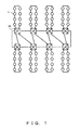
- Fig. 3 illustrates connections of a network inside the processor group 16 in which N processors are completely connected.
- N 4.
- Each processor 20 included in the processor groups 16 is connected to a router 21, and these routers 21 are connected to the network.
- a combination between the processor 20 and the router 21 is referred to as a "nod".
- the routers 21 provided in one processor group are completely connected.
- routers a, b, c, and d are all connected to each other in a one-to-one manner.
- a communications route to the outside of the group is connected to each router 21.
- Fig. 3 illustrates connections of a network inside the processor group 16 in which N processors are completely connected.
- Each processor 20 included in the processor groups 16 is connected to a router 21, and these routers 21 are connected to the network.
- a combination between the processor 20 and the router 21 is referred to as a "nod”.
- the routers 21 provided in one processor group are completely connected.
- a connection to a node outside of a group is realized by a communications route that connects groups in linear.
- Communications routes are provided from respective routers a, b, c, and d in the processor groups to the viewer's left and right sides.
- switches are provided at the ends of communication routes in order to turn back communications.
- Fig. 4 illustrates an entire configuration of a computer system according to the second embodiment.
- 16 completely-connected groups 25 are grouped, and those completely-connected groups 25 are connected in a one-dimensional torus.
- the computer system illustrated in Fig. 4 employs a configuration where connections are implemented in a one-dimensional torus connection and a one-dimensional complete connecting, i.e., in a total of two dimensions.
- the number of interconnection ports of the router 21 is five in total, i.e., two for torus connections, connecting to both sides of the router 21, and three for complete connecting, being completely connected to the other three nodes.
- compartmentalization is performed in units of completely-connected groups, and each compartment has a one-dimensional torus embedding property.
- a one-dimensional torus embedding property means that a route passing through all the nodes constituting a computer system can be traced in a unicursal manner.
- a one-dimensional torus embedding property means that a route passing through all nodes can be traced in a unicursal manner with respect to connections in the respective-dimensional directions.
- the fact that routes can be traced in a unicursal manner means that for any communications, there is a route that passes through all nodes, and accordingly failure avoiding routes can be configured in a static manner beforehand.
- failure avoiding routes can be configured with at most three nodes in a failure state in each compartment, and a one-dimensional torus embedding property is maintained with at most two nodes in a failure state.
- the communication is turned back from that compartment, and can use an alternative route, so that failure avoiding routes can be found.
- the entire system is in a one-dimensional torus with at most two failures in one compartment, and an embedding property of a one-dimensional torus is maintained because there remains one node that operates normally in that compartment.
- Fig. 5 illustrates an entire configuration of a computer system according to the third embodiment.
- the computer system illustrated in Fig. 5 includes thirty-two completely-connected groups 30 in total.
- Each of the completely-connected groups 30 includes six nodes.
- Those six nodes included in each completely-connected group 30 are classified into two sets, each including three nodes.
- the three nodes constituting one set are completely connected to each other.
- the nodes constituting a set of a complete connecting are connected to one of the nodes that constitute the other set.
- the completely-connected groups 30 in Fig. 5 realize two-dimensional complete connecting.
- each completely-connected group 30 is connected in a two-dimensional mesh.
- "Two-dimensional mesh” herein represents a state where the completely-connected groups 30 constituting the computer system in Fig. 5 are arranged in two dimension, i.e., in the longitudinal and crosswise directions in the figure. This means nodes can be expressed by n (i, j, k, 1) by adding indices k and l, which represent mesh connections.
- the computer system illustrated in Fig. 5 connects its nodes in four dimensions, i.e., in two-dimensional mesh connections and two-dimensional complete connecting.
- the number of elements in the completely-connected groups that are connected in linear in the crosswise direction in the figure is eight, and the number of elements in the completely-connected group that are connected in linear in the longitudinal direction is four.
- the number of elements of the completely-connected node is three, and the number of elements in the other dimensions is two.
- the computer system illustrated in Fig. 5 includes 192 nodes in total.
- the dimension of the connections of a network indicates at least how many indices for expressing the location of the node are required when the dimension expresses a node. Accordingly, in the above embodiment, only the one-dimensional case and the two-dimensional case are described, and a network can be configured with combinations of connections in arbitrary dimensions by increasing the number of indices.
- each router includes a total of seven interconnection ports, i.e., four for mesh (two for each dimension) and three for complete connecting (two for three completely-connected nodes, and one for connecting sets of completely-connected nodes).
- compartmentalization is performed in units of completely-connected groups, and each compartment has a two-dimensional torus embedding property.
- a two-dimensional torus embedding property means that connection routes for nodes can be projected onto one two-dimensional torus.
- nodes are two-dimensionally and completely connected, and thus data can arrive at any node using two-dimensional connections, and accordingly a two-dimensional torus can be embedded.
- arbitrary combinations can be adopted between linear dimensions and complete connecting dimensions, and when the completely-connected groups constitute a compartment of 8 ⁇ 4, both a two-dimensional torus of 16 ⁇ 12 and a two-dimensional torus of 24 ⁇ 8 can be embedded.
- the present embodiment makes it possible to perform failure-avoiding routing with up to one node that failed in each compartment.
- a two-dimensional torus embedding property is maintained in a degenerated two-dimensional torus.
- the two-dimensional torus can be maintained by degenerating the compartment into 16 ⁇ 11 by dividing the sixteen nodes when the compartment is 16 ⁇ 12, and by degenerating the compartment into 23 ⁇ 8 by dividing the eight nodes when the compartment is 24 ⁇ 8.
- a two-dimensional torus can be maintained by removing a one-dimensional torus in order to avoid the one node that failed.
- routes for packets are set beforehand and are invariable.
- Alternative routes are also set beforehand.
- the setting is stored as a routing table in each router.
- routes for packets are prevented from arriving at the receiving side in a mixed-up order, which is what would happen when routing is performed by determining alternative routes adaptively, and thereby the load of the packet receiving process is reduced.
- an alternative route for a case when a failure has occurred in a node can be set without setting redundant virtual channels.
- complete connecting is utilized not only for torus compartmentalization, but also for failure-avoiding routes.
- This method can reduce conflicts between failure-avoiding routes and normal communications routes.
- Provision of two virtual channels makes it possible to form a closed ring using linear connections and to avoid deadlock in a torus. This further increases the degrees of freedom in torus compartmentalization.
- a trace can move to target coordinates by a transfer to the next node, and accordingly one virtual channel can realize a deadlock-free situation.
- twice move can be achieved in the dimensions of complete connecting without causing deadlock. This configuration makes it possible to transfer packets using a route that avoids sites with failures.
- an alternative route can be constructed that leads to another route by using a dimension of complete connecting, enters another completely-connected compartment by using a dimension of connections in linear, and reaches the destination node by using a dimension of connections in a series of complete connecting in the completely-connected compartment that the route has currently entered.
- a greater number of ports are used per node for using complete connecting.
- complete connecting can be enclosed within the wiring on a circuit board, which leads to a smaller increase in the implementation cost.
- groups of complete connecting correspond to groups of processors mounted on the circuit board
- complete connecting connections can be realized on a circuit board with shorter wires, and by adopting connections between groups instead of connections between circuit boards, which requires longer wires, the number of wires can be reduced.
Landscapes
- Engineering & Computer Science (AREA)
- Computer Hardware Design (AREA)
- Theoretical Computer Science (AREA)
- Physics & Mathematics (AREA)
- Software Systems (AREA)
- General Engineering & Computer Science (AREA)
- General Physics & Mathematics (AREA)
- Mathematical Physics (AREA)
- Multi Processors (AREA)
Abstract
Description
- The embodiments discussed herein are related to a network that interconnects computer systems or computers.
- Parallel computers include many components, and thus fail highly frequently. Accordingly, it is necessary to be able to operate a parallel computer without replacing a node that has failed so as to reduce the maintenance time consumed to replace the node that has failed. In order to meet this requirement in a multidimensional torus connection network, it is necessary to perform communications using routes not involving a node that has failed. However, having irregularity in the ways of using communication routes, wherein communications are performed through alternative routes when a failure has occurred, requires provision of an additional virtual channel to avoid deadlock. Also, this use increases the load on receiving processes because packets arrive in a mixed-up order. In other words, when alternative routes are formed adaptively for transmitting packets, a packet and its subsequent packet are sometimes transmitted through different routes, which have different traffic levels, and one of those packets may be delayed in transfer. This causes the receiver side to receive packets in a mixed-up order and to be required to perform a process of rearranging those packets into the right order. This increases the load on the receiving process.
- In
Patent Document 1 many virtual channels are used, and communications routes for each channel are statically determined, including alternative routes, and thereby failures are avoided promptly while attaining a deadlock-free condition. - It is known that connecting nodes for parallel computers not in linear but in a ring configuration, i.e., a torus, increases communications speed for parallel computing. Especially in remote communications algorithms, the performance of a torus becomes twice that of a mesh of the same size. In other words, the communication that takes the longest time in a torus is a communication from one node to another node that is half the length of the whole ring away, making the
communications length 1/2 of the whole circle because one end and another end are connected, while a communication route from one end to another end in a mesh network is the communications route that takes the longest time. Accordingly, when a parallel computer is compartmentalized, or processors are grouped and the groups are connected separately, the groups of processors have to be connected in a torus. - In Patent Document 2, a switch with six ports is used, and a compartmentalized mesh, i.e. , groups in which processors are connected in a mesh configuration, are connected in a torus. The two ports are connected to both ends of the compartmentalized mesh, and the four ports connect switches in an expanded torus.
- Implementation of wiring between circuit boards costs more than that within a single circuit board, and the dimensions for connecting mother boards are limited in terms of actual implementation. Thus, one circuit board is handled as a group, and dimensions are increased only in the circuit board so that parallel computation of high-dimensional data can be performed at a high speed. QCDOC is a parallel computer having this configuration, and it was co-developed by RIKEN, Japan, Columbia University, U.S., and Brookhaven National Laboratory, U.S. According to QCDOC, mother boards that each include sixty-four processors connected in a six-dimensional hypercube are connected to each other using three of the six dimensions of the a six-dimensional hypercube. In the six-dimensional space in the inter-processor connections according to QCDOC, three-dimensional distances between mother boards are long, and remaining three-dimensional distances inside the mother boards, are 2.
- Adaptive determination of failure-avoiding routes causes packets to arrive in a mixed-up order and leads to an increase in delay in the receiving process. This also increases a load. With these costs comes and increase in efficiency in using the band, which reduces to the minimum number of virtual channels to be added. By contrast, static determination of failure-avoiding routes leads to a decrease in delay in the receiving process and to a reduction in load, but requires a greater number of virtual channels to be added.
- In some failure-avoiding communications methods in conventional techniques, different normal communications routes are used as failure-avoiding routes. When a band is shared by a normal communications route and a failure-avoiding route, the performance is deteriorated.
Torus compartmentalization according to conventional techniques divides a ring to generate straight connections, reforms the ring as a closed ring by using switches. In such a case, routers need ports for switching. However, only one switching target port is used at a time, which deteriorates the efficiency. -
Fig. 1 illustrates the expanded torus connection disclosed by Patent Document 2.
InFig. 1 ,numerical symbol 10 denotes 6-port switches, andnumerical symbol 11 denotes processors. A mesh compartmentalized by eightprocessors 11 is connected to each of theswitches 10, and a torus can be closed when its size is a multiple of eight (when the number of the includedprocessors 11 is a multiple of eight) according to a setting in eachswitch 10. - In Patent Document 3, a system in which a plurality of buffers are provided in a node in an N-dimensional network for performing communications is disclosed.
- Patent Document 1: Japanese Laid-open Patent Publication No.
6-266684 - Patent Document 2: Japanese Laid-open Patent Publication No.
2005-174289 - Patent Document 3: Japanese Patent No.
3532574 - Non Patent Document 1: "The QCDOC supercomputer: hardware, software, and performance", P.A. Boylea, b, C. Junga, c, and T. Wettigd, CHEP03, La Jolla, CA, March 24-28, 2003 http://phys.columbia.edu/~cqft/
- It is an object of the present invention to provide a network that interconnects processors for a parallel computer that can minimize an increase in virtual channels while suppressing communications loads.
The present invention relates to a network that interconnects processors in a parallel computer in which routers connected to processers are connected to each other, in which each of the routers includes a first port for a line for connecting, in a complete connecting manner, processors belonging to the same group from among groups obtained by grouping all processors included in the parallel computer into a prescribed number of processor groups, and a second port for a line for linear connecting processers belonging to different groups. -
-
Fig. 1 illustrates an expanded torus connection; -
Fig. 2 illustrates a computer system according to a first embodiment; -
Fig. 3 illustrates connections inside a processor group in which processors are completely connected; -
Fig. 4 illustrates an entire configuration of a computer system according to a second embodiment; and -
Fig. 5 illustrates an entire configuration of a computer system according to a third embodiment. -
Fig. 2 illustrates a configuration of a parallel computer system according to the first embodiment of the present invention.
In a parallel computer system according to the present embodiment,communications routes 15 andprocessor groups 16 are used to connect a total of M ×N processors 11 using N+1 ports for processor-node communications.Linear connections 15 are ports for communications between two nodes, and one of the processors included in eachgroup 16 is connected in linear for M groups. Theprocessor groups 16 connectN processors 11 to each other in a complete connecting manner in all combinations. Each port is provided with two virtual channels. M represents the number of thegroups 16, thegroups 16 each having N processors connected in a complete connecting manner to constitute a parallel computer. Additionally, the coordinates of the processors are expressed in two dimensions, i.e., the positions of linear connections and the positions of complete connecting. Complete connecting refers to a connecting form by which all nodes in a group are connected in a one-to-one manner. A node is a set including processors and a router for connecting the processor to a network. -
Fig. 3 illustrates connections of a network inside theprocessor group 16 in which N processors are completely connected. In the example ofFig. 3 , N=4.
Eachprocessor 20 included in theprocessor groups 16 is connected to arouter 21, and theserouters 21 are connected to the network. InFig. 3 , a combination between theprocessor 20 and therouter 21 is referred to as a "nod". InFig. 3 , therouters 21 provided in one processor group are completely connected. In other words, routers a, b, c, and d are all connected to each other in a one-to-one manner. Also, a communications route to the outside of the group is connected to eachrouter 21. In the case ofFig. 3 , a connection to a node outside of a group is realized by a communications route that connects groups in linear. Communications routes are provided from respective routers a, b, c, and d in the processor groups to the viewer's left and right sides. In the processor groups located at the ends of the linear connection, switches are provided at the ends of communication routes in order to turn back communications. - Additionally, a configuration of each node in
Fig. 3 is common over all the embodiments.
Fig. 4 illustrates an entire configuration of a computer system according to the second embodiment.
In the computer system illustrated inFig. 4 , 16 completely-connectedgroups 25 are grouped, and those completely-connectedgroups 25 are connected in a one-dimensional torus. In other words, the computer system illustrated inFig. 4 employs a configuration where connections are implemented in a one-dimensional torus connection and a one-dimensional complete connecting, i.e., in a total of two dimensions. In this configuration, there are sixteen completely-connectedgroups 25 in a torus connection and fournodes 26 that are included in the completely-connected groups, and thus the computer system illustrated inFig. 4 includes sixty-four nodes in total. The number of interconnection ports of therouter 21 is five in total, i.e., two for torus connections, connecting to both sides of therouter 21, and three for complete connecting, being completely connected to the other three nodes. - In the computer system illustrated in
Fig. 4 , compartmentalization is performed in units of completely-connected groups, and each compartment has a one-dimensional torus embedding property. A one-dimensional torus embedding property means that a route passing through all the nodes constituting a computer system can be traced in a unicursal manner. When complete connecting in each group is two-dimensional or higher, a one-dimensional torus embedding property means that a route passing through all nodes can be traced in a unicursal manner with respect to connections in the respective-dimensional directions. The fact that routes can be traced in a unicursal manner means that for any communications, there is a route that passes through all nodes, and accordingly failure avoiding routes can be configured in a static manner beforehand. In the present embodiment, failure avoiding routes can be configured with at most three nodes in a failure state in each compartment, and a one-dimensional torus embedding property is maintained with at most two nodes in a failure state. In other words, when three nodes have failed in one compartment, the communication is turned back from that compartment, and can use an alternative route, so that failure avoiding routes can be found. Also, the entire system is in a one-dimensional torus with at most two failures in one compartment, and an embedding property of a one-dimensional torus is maintained because there remains one node that operates normally in that compartment. -
Fig. 5 illustrates an entire configuration of a computer system according to the third embodiment.
The computer system illustrated inFig. 5 includes thirty-two completely-connectedgroups 30 in total. Each of the completely-connectedgroups 30 includes six nodes. Those six nodes included in each completely-connectedgroup 30 are classified into two sets, each including three nodes. The three nodes constituting one set are completely connected to each other. The nodes constituting a set of a complete connecting are connected to one of the nodes that constitute the other set. In other words, the completely-connectedgroups 30 inFig. 5 realize two-dimensional complete connecting. - Now, connections of nodes in the completely-connected
groups 30 are explained. When nodes are expressed by n (i, j), where i and j are natural numbers, the respective nodes are connected when j is fixed and i is changed. Next, the respective nodes are connected when i is fixed and j is changed. In this situation, the connections between the completely-connectedgroups 30 inFig. 5 are two dimensional. In the case ofFig. 5 , i={1, 2, 3} and j={1,2}. - Also, in the computer system illustrated in
Fig. 5 , each completely-connectedgroup 30 is connected in a two-dimensional mesh. "Two-dimensional mesh" herein represents a state where the completely-connectedgroups 30 constituting the computer system inFig. 5 are arranged in two dimension, i.e., in the longitudinal and crosswise directions in the figure. This means nodes can be expressed by n (i, j, k, 1) by adding indices k and l, which represent mesh connections. - As described above, the computer system illustrated in
Fig. 5 connects its nodes in four dimensions, i.e., in two-dimensional mesh connections and two-dimensional complete connecting. In this configuration, the number of elements in the completely-connected groups that are connected in linear in the crosswise direction in the figure is eight, and the number of elements in the completely-connected group that are connected in linear in the longitudinal direction is four. Also, in each completely-connected group, the number of elements of the completely-connected node is three, and the number of elements in the other dimensions is two. In other words, the computer system illustrated inFig. 5 includes 192 nodes in total. - As described above, the dimension of the connections of a network indicates at least how many indices for expressing the location of the node are required when the dimension expresses a node. Accordingly, in the above embodiment, only the one-dimensional case and the two-dimensional case are described, and a network can be configured with combinations of connections in arbitrary dimensions by increasing the number of indices.
- In
Fig. 5 , each router includes a total of seven interconnection ports, i.e., four for mesh (two for each dimension) and three for complete connecting (two for three completely-connected nodes, and one for connecting sets of completely-connected nodes). - In the computer system in
Fig. 5 , compartmentalization is performed in units of completely-connected groups, and each compartment has a two-dimensional torus embedding property. A two-dimensional torus embedding property means that connection routes for nodes can be projected onto one two-dimensional torus. In other words, in a complete connecting configuration, nodes are two-dimensionally and completely connected, and thus data can arrive at any node using two-dimensional connections, and accordingly a two-dimensional torus can be embedded. Additionally, arbitrary combinations can be adopted between linear dimensions and complete connecting dimensions, and when the completely-connected groups constitute a compartment of 8×4, both a two-dimensional torus of 16×12 and a two-dimensional torus of 24×8 can be embedded. - The present embodiment makes it possible to perform failure-avoiding routing with up to one node that failed in each compartment. Also, a two-dimensional torus embedding property is maintained in a degenerated two-dimensional torus. When completely-connected groups constitute an 8×4 compartment, the two-dimensional torus can be maintained by degenerating the compartment into 16×11 by dividing the sixteen nodes when the compartment is 16×12, and by degenerating the compartment into 23×8 by dividing the eight nodes when the compartment is 24×8. In other words, when one node has failed, a two-dimensional torus can be maintained by removing a one-dimensional torus in order to avoid the one node that failed.
- In the above embodiment, routes for packets are set beforehand and are invariable. Alternative routes are also set beforehand. The setting is stored as a routing table in each router. By statically setting routes for packets beforehand, packets are prevented from arriving at the receiving side in a mixed-up order, which is what would happen when routing is performed by determining alternative routes adaptively, and thereby the load of the packet receiving process is reduced. Also, by connecting groups of completely-connected nodes in linear, an alternative route for a case when a failure has occurred in a node can be set without setting redundant virtual channels.
- It is possible to trace, in a unicursal manner, a route passing through all processors that are connected two-dimensionally, i.e., connections in linear and complete connecting. This is referred to as a one-dimensional torus embedding property, and can increase in speed similarly to a one-dimensional torus. In conventional methods, completely-connected compartments are closed in a torus, which requires switches in addition to routers. However, in the present embodiment, depending upon combinations between dimensions of linear connections and complete connecting, routers alone can provide a one-dimensional torus embedding property to each compartment.
- In the present embodiment, complete connecting is utilized not only for torus compartmentalization, but also for failure-avoiding routes. This method can reduce conflicts between failure-avoiding routes and normal communications routes.
Provision of two virtual channels makes it possible to form a closed ring using linear connections and to avoid deadlock in a torus. This further increases the degrees of freedom in torus compartmentalization. Also, in the dimensions of complete connecting, a trace can move to target coordinates by a transfer to the next node, and accordingly one virtual channel can realize a deadlock-free situation. When two virtual channels are used, twice move can be achieved in the dimensions of complete connecting without causing deadlock. This configuration makes it possible to transfer packets using a route that avoids sites with failures. In other words, when a node has failed and that node has to be avoided, an alternative route can be constructed that leads to another route by using a dimension of complete connecting, enters another completely-connected compartment by using a dimension of connections in linear, and reaches the destination node by using a dimension of connections in a series of complete connecting in the completely-connected compartment that the route has currently entered. - In conventional methods, in addition to two virtual channels for avoiding deadlock in a torus, an additional virtual channel is required for failure-avoiding route, which increases hardware cost. The present embodiment makes it possible, with two virtual channels, both to avoid deadlock in a torus and establish a failure-avoiding route.
- In the present embodiment, a greater number of ports are used per node for using complete connecting. However, complete connecting can be enclosed within the wiring on a circuit board, which leads to a smaller increase in the implementation cost. In other words, by making groups of complete connecting correspond to groups of processors mounted on the circuit board, complete connecting connections can be realized on a circuit board with shorter wires, and by adopting connections between groups instead of connections between circuit boards, which requires longer wires, the number of wires can be reduced.
Claims (12)
- A network that interconnects nodes in a computer system in which a plurality of nodes are interconnected,
each of the nodes comprising:a first group of ports for links connecting, in a multi-dimensional complete connection, nodes belonging to the same group from among groups obtained by grouping nodes included in the computer system into a prescribed number of groups; anda second group of ports for links connecting, in a multi-dimensional linear connection, nodes belonging to different groups. - The network according to claim 1, wherein:linear connections constitute tori by connecting both ends of a linear connection.
- The network according to claim 2, wherein:one linear connection constitutes a one-dimensional torus.
- The network according to claim 2, wherein:two linear connections constitute a two-dimensional torus.
- The network according to claim 1, wherein:a one-dimensional complete connection connects processors belonging to the group.
- The network according to claim 1, wherein:a two-dimensional complete connection connects processors belonging to the group.
- The network according to claim 1, wherein:the group is constituted of a processor group mounted on one circuit board.
- The network according to claim 7, wherein:the linear connection is a line that connects circuit boards.
- The network according to claim 1, wherein:the linear connection includes two virtual channels.
- The network according to claim 1, wherein:a communication between routers is a packet communication.
- A computer system in which a plurality of nodes are connected, comprising:M (M is an integer equal to or greater than 1) node groups made by completely connecting N (N is an integer equal to or greater than 1) nodes from among nodes constituting the computer system, wherein:nodes of the N nodes constituting the M node groups are connected to each other in linear.
- A computer system according to claim 11, wherein:the node comprises a processor and a router to which a processor is connected.
Priority Applications (1)
| Application Number | Priority Date | Filing Date | Title |
|---|---|---|---|
| EP18167397.1A EP3382569A1 (en) | 2008-05-15 | 2008-05-15 | Network for interconnecting computers |
Applications Claiming Priority (1)
| Application Number | Priority Date | Filing Date | Title |
|---|---|---|---|
| PCT/JP2008/001220 WO2009139024A1 (en) | 2008-05-15 | 2008-05-15 | Network for mutually connecting computers |
Related Child Applications (1)
| Application Number | Title | Priority Date | Filing Date |
|---|---|---|---|
| EP18167397.1A Division EP3382569A1 (en) | 2008-05-15 | 2008-05-15 | Network for interconnecting computers |
Publications (2)
| Publication Number | Publication Date |
|---|---|
| EP2282269A1 true EP2282269A1 (en) | 2011-02-09 |
| EP2282269A4 EP2282269A4 (en) | 2012-01-04 |
Family
ID=41318408
Family Applications (2)
| Application Number | Title | Priority Date | Filing Date |
|---|---|---|---|
| EP18167397.1A Ceased EP3382569A1 (en) | 2008-05-15 | 2008-05-15 | Network for interconnecting computers |
| EP08751738A Ceased EP2282269A4 (en) | 2008-05-15 | 2008-05-15 | MUTUAL CONNECTION NETWORK OF COMPUTERS |
Family Applications Before (1)
| Application Number | Title | Priority Date | Filing Date |
|---|---|---|---|
| EP18167397.1A Ceased EP3382569A1 (en) | 2008-05-15 | 2008-05-15 | Network for interconnecting computers |
Country Status (4)
| Country | Link |
|---|---|
| US (1) | US8504731B2 (en) |
| EP (2) | EP3382569A1 (en) |
| JP (1) | JP5212469B2 (en) |
| WO (1) | WO2009139024A1 (en) |
Cited By (1)
| Publication number | Priority date | Publication date | Assignee | Title |
|---|---|---|---|---|
| CN104079491A (en) * | 2014-07-07 | 2014-10-01 | 中国科学院计算技术研究所 | Router for high-dimensionality network and routing method |
Families Citing this family (5)
| Publication number | Priority date | Publication date | Assignee | Title |
|---|---|---|---|---|
| JP5750963B2 (en) | 2011-03-22 | 2015-07-22 | 富士通株式会社 | Parallel computer system, control apparatus, parallel computer system control method, and parallel computer system control program |
| WO2014045444A1 (en) | 2012-09-24 | 2014-03-27 | 富士通株式会社 | Parallel computer, node device, and method for controlling parallel computer |
| JPWO2018097015A1 (en) * | 2016-11-28 | 2019-10-17 | 株式会社エスペラントシステム | Distributed system |
| GB2562520A (en) * | 2017-05-17 | 2018-11-21 | John Hamlin Derrick | Digital processing connectivity |
| TWI661700B (en) * | 2017-08-11 | 2019-06-01 | 國立成功大學 | Network topology system and topology building method thereof |
Family Cites Families (25)
| Publication number | Priority date | Publication date | Assignee | Title |
|---|---|---|---|---|
| JPS532574B2 (en) | 1972-12-29 | 1978-01-30 | ||
| US4253144A (en) * | 1978-12-21 | 1981-02-24 | Burroughs Corporation | Multi-processor communication network |
| US5280474A (en) * | 1990-01-05 | 1994-01-18 | Maspar Computer Corporation | Scalable processor to processor and processor-to-I/O interconnection network and method for parallel processing arrays |
| JP3679813B2 (en) * | 1991-07-22 | 2005-08-03 | 株式会社日立製作所 | Parallel computer |
| GB9201126D0 (en) * | 1992-01-20 | 1992-03-11 | Madge Networks Ltd | Communication system |
| JPH06266684A (en) | 1993-03-15 | 1994-09-22 | Toshiba Corp | Interprocessor routing system |
| US5583990A (en) * | 1993-12-10 | 1996-12-10 | Cray Research, Inc. | System for allocating messages between virtual channels to avoid deadlock and to optimize the amount of message traffic on each type of virtual channel |
| US5701416A (en) | 1995-04-13 | 1997-12-23 | Cray Research, Inc. | Adaptive routing mechanism for torus interconnection network |
| US20020085547A1 (en) * | 1998-09-17 | 2002-07-04 | Mcnamara Tod W. | High density network topology |
| US6301623B1 (en) * | 1998-12-24 | 2001-10-09 | 3Com Corporation | Computer network with a plurality of identically addressed devices |
| US6598145B1 (en) * | 1999-02-12 | 2003-07-22 | Avici Systems | Irregular network |
| JP4377033B2 (en) * | 2000-05-23 | 2009-12-02 | 富士通マイクロエレクトロニクス株式会社 | Data transfer control method and apparatus |
| US6853635B1 (en) * | 2000-07-24 | 2005-02-08 | Nortel Networks Limited | Multi-dimensional lattice network |
| US7444422B1 (en) * | 2000-10-10 | 2008-10-28 | Nortel Networks Limited | Multicast when forwarding information is unknown |
| US20030041152A1 (en) * | 2001-08-21 | 2003-02-27 | David Schmeltzle | Distributed communication system |
| US6854035B2 (en) * | 2001-10-05 | 2005-02-08 | International Business Machines Corporation | Storage area network methods and apparatus for display and management of a hierarchical file system extension policy |
| US7730077B2 (en) * | 2002-09-18 | 2010-06-01 | Netezza Corporation | Intelligent storage device controller |
| JP2005157653A (en) | 2003-11-25 | 2005-06-16 | Ip Flex Kk | Data processor and data processing method |
| US7191311B2 (en) | 2003-12-13 | 2007-03-13 | International Business Machines Corporation | Method and system of interconnecting processors of a parallel computer to facilitate torus partitioning |
| CN100334857C (en) * | 2004-09-27 | 2007-08-29 | 华为技术有限公司 | Looped network and its service realizing method |
| US7724739B2 (en) * | 2005-03-18 | 2010-05-25 | Cisco Technology, Inc. | Source specific multicast layer 2 networking device and method |
| US8131871B2 (en) * | 2006-01-12 | 2012-03-06 | Cisco Technology, Inc. | Method and system for the automatic reroute of data over a local area network |
| JP5055942B2 (en) * | 2006-10-16 | 2012-10-24 | 富士通株式会社 | Computer cluster |
| US7831709B1 (en) * | 2008-02-24 | 2010-11-09 | Sprint Communications Company L.P. | Flexible grouping for port analysis |
| US8279867B2 (en) * | 2008-03-02 | 2012-10-02 | Jeffrey Alan Carley | Method and apparatus for reducing flood traffic in switches |
-
2008
- 2008-05-15 EP EP18167397.1A patent/EP3382569A1/en not_active Ceased
- 2008-05-15 WO PCT/JP2008/001220 patent/WO2009139024A1/en not_active Ceased
- 2008-05-15 EP EP08751738A patent/EP2282269A4/en not_active Ceased
- 2008-05-15 JP JP2010511791A patent/JP5212469B2/en active Active
-
2010
- 2010-11-09 US US12/942,291 patent/US8504731B2/en active Active
Cited By (2)
| Publication number | Priority date | Publication date | Assignee | Title |
|---|---|---|---|---|
| CN104079491A (en) * | 2014-07-07 | 2014-10-01 | 中国科学院计算技术研究所 | Router for high-dimensionality network and routing method |
| CN104079491B (en) * | 2014-07-07 | 2018-04-27 | 中国科学院计算技术研究所 | A kind of router and method for routing towards high-dimensional network |
Also Published As
| Publication number | Publication date |
|---|---|
| JP5212469B2 (en) | 2013-06-19 |
| EP3382569A1 (en) | 2018-10-03 |
| US8504731B2 (en) | 2013-08-06 |
| JPWO2009139024A1 (en) | 2011-09-08 |
| US20110055428A1 (en) | 2011-03-03 |
| WO2009139024A1 (en) | 2009-11-19 |
| EP2282269A4 (en) | 2012-01-04 |
Similar Documents
| Publication | Publication Date | Title |
|---|---|---|
| US7889725B2 (en) | Computer cluster | |
| KR101937211B1 (en) | Heterogeneous channel capacities in an interconnect | |
| US8504731B2 (en) | Network for interconnecting computers | |
| JP5540609B2 (en) | Parallel computing system and communication control program | |
| US20150334035A1 (en) | Apparatus and method for collective communication in a parallel computer system | |
| Kumar et al. | Optimization of all-to-all communication on the blue gene/l supercomputer | |
| US11018896B2 (en) | Information processing apparatus and information processing method | |
| US7486619B2 (en) | Multidimensional switch network | |
| US9270484B2 (en) | Data center network using circuit switching | |
| KR20130037101A (en) | Coarse-grained reconfigurable array based on a static router | |
| US8755287B2 (en) | Network managing device and network managing method | |
| CN102368739A (en) | Broadcast mechanism routing algorithm orienting to packet-circuit switch on-chip router | |
| US9258358B2 (en) | Parallel computing system and control method of parallel computing system | |
| CN115002584A (en) | Reconfigurable computing platform using optical network with one-to-many optical switch | |
| EP2078261A2 (en) | System and method for networking computer clusters | |
| US10616140B2 (en) | Information processing system and information processing method | |
| US20190146802A1 (en) | Information processing apparatus, arithmetic processing apparatus, and control method for information processing apparatus | |
| CN119743450A (en) | Message transmission method and device of network-on-chip, electronic equipment and storage medium | |
| Baccour et al. | Ptnet: A parameterizable data center network | |
| US8667251B2 (en) | Electronic chip and integrated circuit including a split routing unit having first-level routers for intra-layer transmissions and second-level routers for inter-layer transmissions and transmissions to the processing units | |
| KR102691170B1 (en) | Technology of flexiblex interconnect topology and packet controlling method in host network with silicon-photonics interface for high-performance computing | |
| HK40081215A (en) | Reconfigurable computing pods using optical networks with one-to-many optical switches | |
| HK40044238A (en) | Reconfigurable computing pods using optical networks with one-to-many optical switches | |
| HK40044238B (en) | Reconfigurable computing pods using optical networks with one-to-many optical switches | |
| Safaei et al. | Adaptive wormhole routing in tori with faults: A mathematical approach |
Legal Events
| Date | Code | Title | Description |
|---|---|---|---|
| PUAI | Public reference made under article 153(3) epc to a published international application that has entered the european phase |
Free format text: ORIGINAL CODE: 0009012 |
|
| 17P | Request for examination filed |
Effective date: 20101208 |
|
| AK | Designated contracting states |
Kind code of ref document: A1 Designated state(s): AT BE BG CH CY CZ DE DK EE ES FI FR GB GR HR HU IE IS IT LI LT LU LV MC MT NL NO PL PT RO SE SI SK TR |
|
| AX | Request for extension of the european patent |
Extension state: AL BA MK RS |
|
| DAX | Request for extension of the european patent (deleted) | ||
| A4 | Supplementary search report drawn up and despatched |
Effective date: 20111202 |
|
| RIC1 | Information provided on ipc code assigned before grant |
Ipc: G06F 15/173 20060101AFI20111128BHEP |
|
| STAA | Information on the status of an ep patent application or granted ep patent |
Free format text: STATUS: EXAMINATION IS IN PROGRESS |
|
| 17Q | First examination report despatched |
Effective date: 20161115 |
|
| APBK | Appeal reference recorded |
Free format text: ORIGINAL CODE: EPIDOSNREFNE |
|
| APBN | Date of receipt of notice of appeal recorded |
Free format text: ORIGINAL CODE: EPIDOSNNOA2E |
|
| APBR | Date of receipt of statement of grounds of appeal recorded |
Free format text: ORIGINAL CODE: EPIDOSNNOA3E |
|
| APAF | Appeal reference modified |
Free format text: ORIGINAL CODE: EPIDOSCREFNE |
|
| APAF | Appeal reference modified |
Free format text: ORIGINAL CODE: EPIDOSCREFNE |
|
| REG | Reference to a national code |
Ref country code: DE Ref legal event code: R003 |
|
| APBT | Appeal procedure closed |
Free format text: ORIGINAL CODE: EPIDOSNNOA9E |
|
| STAA | Information on the status of an ep patent application or granted ep patent |
Free format text: STATUS: THE APPLICATION HAS BEEN REFUSED |
|
| 18R | Application refused |
Effective date: 20210726 |