EP2282072A1 - Inner and outer ring, and ball bearing made of sheet metal - Google Patents
Inner and outer ring, and ball bearing made of sheet metal Download PDFInfo
- Publication number
- EP2282072A1 EP2282072A1 EP10171984A EP10171984A EP2282072A1 EP 2282072 A1 EP2282072 A1 EP 2282072A1 EP 10171984 A EP10171984 A EP 10171984A EP 10171984 A EP10171984 A EP 10171984A EP 2282072 A1 EP2282072 A1 EP 2282072A1
- Authority
- EP
- European Patent Office
- Prior art keywords
- fit
- inner ring
- fit portion
- outer ring
- shaft
- Prior art date
- Legal status (The legal status is an assumption and is not a legal conclusion. Google has not performed a legal analysis and makes no representation as to the accuracy of the status listed.)
- Granted
Links
- 239000002184 metal Substances 0.000 title description 4
- 230000007423 decrease Effects 0.000 claims description 4
- 230000002093 peripheral effect Effects 0.000 abstract description 8
- 238000010438 heat treatment Methods 0.000 description 4
- 238000005299 abrasion Methods 0.000 description 2
- 230000015572 biosynthetic process Effects 0.000 description 2
- 238000005255 carburizing Methods 0.000 description 2
- 230000005489 elastic deformation Effects 0.000 description 2
- 238000010791 quenching Methods 0.000 description 2
- 230000000171 quenching effect Effects 0.000 description 2
- 230000002159 abnormal effect Effects 0.000 description 1
Images




Classifications
-
- F—MECHANICAL ENGINEERING; LIGHTING; HEATING; WEAPONS; BLASTING
- F16—ENGINEERING ELEMENTS AND UNITS; GENERAL MEASURES FOR PRODUCING AND MAINTAINING EFFECTIVE FUNCTIONING OF MACHINES OR INSTALLATIONS; THERMAL INSULATION IN GENERAL
- F16C—SHAFTS; FLEXIBLE SHAFTS; ELEMENTS OR CRANKSHAFT MECHANISMS; ROTARY BODIES OTHER THAN GEARING ELEMENTS; BEARINGS
- F16C27/00—Elastic or yielding bearings or bearing supports, for exclusively rotary movement
- F16C27/04—Ball or roller bearings, e.g. with resilient rolling bodies
-
- F—MECHANICAL ENGINEERING; LIGHTING; HEATING; WEAPONS; BLASTING
- F16—ENGINEERING ELEMENTS AND UNITS; GENERAL MEASURES FOR PRODUCING AND MAINTAINING EFFECTIVE FUNCTIONING OF MACHINES OR INSTALLATIONS; THERMAL INSULATION IN GENERAL
- F16C—SHAFTS; FLEXIBLE SHAFTS; ELEMENTS OR CRANKSHAFT MECHANISMS; ROTARY BODIES OTHER THAN GEARING ELEMENTS; BEARINGS
- F16C33/00—Parts of bearings; Special methods for making bearings or parts thereof
- F16C33/30—Parts of ball or roller bearings
- F16C33/58—Raceways; Race rings
- F16C33/588—Races of sheet metal
-
- F—MECHANICAL ENGINEERING; LIGHTING; HEATING; WEAPONS; BLASTING
- F16—ENGINEERING ELEMENTS AND UNITS; GENERAL MEASURES FOR PRODUCING AND MAINTAINING EFFECTIVE FUNCTIONING OF MACHINES OR INSTALLATIONS; THERMAL INSULATION IN GENERAL
- F16C—SHAFTS; FLEXIBLE SHAFTS; ELEMENTS OR CRANKSHAFT MECHANISMS; ROTARY BODIES OTHER THAN GEARING ELEMENTS; BEARINGS
- F16C13/00—Rolls, drums, discs, or the like; Bearings or mountings therefor
- F16C13/02—Bearings
-
- F—MECHANICAL ENGINEERING; LIGHTING; HEATING; WEAPONS; BLASTING
- F16—ENGINEERING ELEMENTS AND UNITS; GENERAL MEASURES FOR PRODUCING AND MAINTAINING EFFECTIVE FUNCTIONING OF MACHINES OR INSTALLATIONS; THERMAL INSULATION IN GENERAL
- F16C—SHAFTS; FLEXIBLE SHAFTS; ELEMENTS OR CRANKSHAFT MECHANISMS; ROTARY BODIES OTHER THAN GEARING ELEMENTS; BEARINGS
- F16C19/00—Bearings with rolling contact, for exclusively rotary movement
- F16C19/02—Bearings with rolling contact, for exclusively rotary movement with bearing balls essentially of the same size in one or more circular rows
- F16C19/04—Bearings with rolling contact, for exclusively rotary movement with bearing balls essentially of the same size in one or more circular rows for radial load mainly
- F16C19/06—Bearings with rolling contact, for exclusively rotary movement with bearing balls essentially of the same size in one or more circular rows for radial load mainly with a single row or balls
Definitions
- the invention relates to a ball bearing, and an inner ring and an outer ring thereof.
- a ball bearing 101 shown in FIG. 5 is used as an existing ball bearing used for a fuser roller or a heating roller of a copying machine.
- the ball bearing 101 is arranged between a shaft end portion 102A of a rotary shaft (roller) 102 and a metal-sheet housing 103, and fitted to the shaft end portion 102A and the metal-sheet housing 103.
- a snap ring 105 is fitted in an annular groove 104 formed in the shaft end portion 102A. The snap ring 105 restricts the axial position of the ball bearing 101 to prevent the ball bearing 101 from dropping off.
- the ball bearing 101 and the metal-sheet housing 103 are loosely fitted to each other and the ball bearing 101 and the shaft end portion 102A are also loosely fitted to each other.
- JP-A-51-86662 describes that a bearing 201 is locked to a shaft 203 by a wire 206, a snap ring or a circlip so that relative movement between these members in the axial direction is restricted, as shown in FIG 6 .
- JP-A-51-86662 Although it is possible to suppress formation of axial backlash between the bearing 201 and the shaft 203 to some extent, it is not possible to prevent generation of creep.
- JP-A-09-144763 describes that an inner ring and an outer ring are produced by pressing metal sheets. According to the technology described in JP-A-09-144763 , however, the radial movement of an inner peripheral face of the inner ring is restricted by an end face, an outer side raceway groove and a load backup portion. Therefore, it is not easy to tightly fit the inner ring to a rotary shaft. If the inner ring is forcibly fitted to the rotary shaft, unexpected deformation may occur.
- An aspect of the invention relates to an inner ring that includes: a first fit portion that extends in such a manner that a diameter of the first fit portion gradually increases toward a first axial end of the inner ring, and that has a spring property; a first end portion that extends radially outward from a first axial end portion of the first fit portion; a first shoulder portion that extends from an outer periphery of the first end portion toward a second axial end of the inner ring, and that faces the first fit portion in a radial direction with a clearance left between the first shoulder portion and the first fit portion; a second fit portion that is formed next to the first fit portion in an axial direction, that extends in such a manner that a diameter of the second fit portion gradually increases toward the second axial end of the inner ring, and that has a spring property; a second end portion that extends radially outward from a second axial end portion of the second fit portion; a second shoulder portion that extends from an outer periphery of the second
- the first fit portion and the second fit portion of the inner ring have a spring property. Therefore, the first and second fit portions may be flexed radially outward by elasticity thereof and then fitted to the shaft.
- the inner ring is tightly fitted to the shaft with a set interference with respect to the shaft. Accordingly, it is easy to fit/remove the inner ring to/from the shaft. Therefore, an outer peripheral face of the shaft is pushed radially inward by elasticity of the first and second fit portions, that is, the inner ring is tightly fitted to the shaft, without reducing the ease of fitting/removing the inner ring to/from the shaft. As a result, it is possible to minimize generation of creep.
- FIG. 1 shows a ball bearing that includes an inner ring 1 according to a first embodiment of the invention.
- the ball bearing includes the inner ring 1, an outer ring 2 that serves as an outer member, and a plurality of balls 3 that are arranged between an inner ring raceway surface 1A of the inner ring 1 and an outer ring raceway surface 2A of the outer ring 2 so as to be able to roll therebetween.
- Shield plates 5 and 6 are fitted to shoulder portions of the outer ring 2, which are at respective axial ends of the outer ring 2.
- the ball bearing includes a retainer 7 that retains the plurality of balls 3.
- the inner ring 1 has an annular first fit portion 11 and an annular first end portion 12.
- the first fit portion 11 extends in such a manner that the diameter of the first fit portion 11 gradually increases toward a first axial end of the inner ring 1.
- the first fit portion 11 has a spring property.
- the first end portion 12 extends radially outward from a first axial end portion 11A of the first fit member 11.
- the inner ring 1 has a first shoulder portion 13 that extends from an outer periphery of the first end portion 12 toward a second axial end of the inner ring 1, and that faces the first fit portion 11 in the radial direction with a clearance left between the first shoulder portion 13 and the first fit portion 11.
- the inner ring 1 has an annular second fit portion 15 and an annular second end portion 16.
- the second fit portion 15 is formed next to the first fit portion 11 in the axial direction with a clearance left between the second fit portion 15 and the first fit portion 11.
- the second fit portion 15 extends in such a manner that the diameter of the second fit portion 15 gradually increases toward the second axial end of the inner ring 1.
- the second fit portion 15 has a spring property.
- the second end portion 16 extends radially outward from a second axial end portion 15A of the second fit member 15.
- the inner ring 1 has a second shoulder portion 17 that extends from an outer periphery of the second end portion 16 toward the first axial end of the inner ring 1, and that faces the second fit portion 15 in the radial direction with a clearance left between the second shoulder portion 17 and the second fit portion 15.
- the inner ring 1 has a raceway portion 18 that has an arc-shaped cross section.
- the raceway portion 18 is contiguous to the first shoulder portion 13 and the second shoulder portion 17, and has the inner ring raceway surface 1A.
- the raceway portion 18 faces the first fit portion 11 and the second fit portion 15 in the radial direction with a clearance left between the raceway portion 18 and the first and second fit portions 11 and 15.
- the inner ring 1 is produced by pressing a metal sheet, and a spring property is imparted to the inner ring 1 by carburizing and quenching.
- the first fit portion 11 and the second fit portion 15 of the inner ring 1 according to the first embodiment have a spring property. Therefore, as shown in FIG 2 , the first fit portion 11 and the second fit portion 15 may be flexed radially outward by elasticity thereof and then fitted to a shaft 20. Thus, the inner ring 1 is tightly fitted to the shaft 20 with a set interference with respect to the shaft 20. Accordingly, it is easy to fit the inner ring 1 to the shaft 20 and to remove the inner ring 1 from the shaft 20.
- eccentricity of the shaft 20 is tolerated because the first fit portion 11 and the second fit portion 15 have a spring property.
- the first fit portion 11 and the second fit portion 15 are flexed so as to extend at substantially right angle to the first end portion 12 and the second end portion 16, respectively, and the first end portion 12 and the second end portion 16, which extend from the axial ends of the first shoulder portion 13 and the second shoulder portion 17, respectively, at substantially right angle, bear a load from the shaft 20. Therefore, when the inner ring 1 is fitted to the shaft 20, elastic deformation of the first and second fit portions 11 and 15 does not exert a large influence.
- the ball bearing that includes the inner ring 1 With the ball bearing that includes the inner ring 1, it is possible to minimize generation of creep by pushing the outer peripheral face of the shaft 20 radially inward using a spring property of the first and second fit portions 11 and 15 of the inner ring 1.
- the ball bearing that includes the inner ring 1 is preferably used to minimize generation of creep when high degree of ease of fitting the ball bearing is demanded although a demand for the accuracy of a shaft center is relatively low.
- the ball bearing 1 is preferably used to support a fuser roller or a heating roller of a copying machine.
- the ball bearing includes an inner ring 31 that serves as an inner member, the outer ring 32, and a plurality of balls 33 that are arranged between an inner ring raceway surface 31A of the inner ring 31 and an outer ring raceway surface 32A of the outer ring 32 so as to be able to roll therebetween.
- the ball bearing includes a retainer 37 that retains the plurality of balls 33.
- the outer ring 32 has an annular first fit portion 41 and an annular first end portion 42.
- the first fit portion 41 extends in such a manner that the diameter of the first fit portion 41 gradually decreases toward a first axial end of the outer ring 32.
- the first fit portion 41 has a spring property.
- the first end portion 42 extends radially inward from a first axial end portion of the first fit member 41.
- the outer ring 32 has a first shoulder portion 43 that extends from an inner periphery of the first end portion 42 toward a second axial end of the outer ring 32, and that faces the first fit portion 41 in the radial direction with a clearance left between the first shoulder portion 43 and the first fit portion 41.
- the outer ring 32 has an annular second fit portion 45 and an annular second end portion 46.
- the second fit portion 45 is formed next to the first fit portion 41 in the axial direction with a clearance left between the second fit portion 45 and the first fit portion 41.
- the second fit portion 45 extends in such a manner that the diameter of the second fit portion 45 gradually decreases toward the second axial end of the outer ring 32.
- the second fit portion 45 has a spring property.
- the second end portion 46 extends radially inward from a second axial end portion of the second fit member 45.
- the outer ring 32 has a second shoulder portion 47 that extends from an inner periphery of the second end portion 46 toward the first axial end of the outer ring 32, and that faces the second fit portion 45 in the radial direction with a clearance left between the second shoulder portion 47 and the second fit portion 45.
- the outer ring 32 has a raceway portion 48 that has an arc-shaped cross section.
- the raceway portion 48 is contiguous to the first shoulder portion 43 and the second shoulder portion 47, and has the outer ring raceway surface 32A.
- the raceway portion 48 faces the first fit portion 41 and the second fit portion 45 in the radial direction with a clearance left between the raceway portion 48 and the first and second fit portions 41 and 45.
- the outer ring 32 is produced by pressing a metal sheet, and a spring property is imparted to the outer ring 32 by carburizing and quenching.
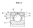
- the first fit portion 41 and the second fit portion 45 of the outer ring 32 according to the second embodiment have a spring property. Therefore, as shown in FIG. 4 , the first fit portion 41 and the second fit portion 45 may be flexed radially inward by elasticity thereof and then fitted into a housing 50.
- the outer ring 32 is tightly fitted to the housing 50 with a set interference with respect to the housing 50. Accordingly, it is easy to fit the outer ring 32 to the housing 50 and to remove the outer ring 32 from the housing 50.
- the outer ring 32 is tightly fitted to the housing 50 without reducing the ease of fitting the outer ring 32 to the housing 50 and removing the outer ring 32 from the housing 50. Therefore, the inner peripheral face of the housing 50 is pushed radially outward by elasticity of the first and second fit portions 41 and 45. As a result, it is possible to minimize generation of creep.
- eccentricity of the housing 50 is tolerated because the first fit portion 41 and the second fit portion 45 have a spring property.
- the first fit portion 41 and the second fit portion 45 are flexed so as to extend at substantially right angle to the first end portion 42 and the second end portion 46, respectively, and the first end portion 42 and the second end portion 46, which extend from the axial ends of the first shoulder portion 43 and the second shoulder portion 47, respectively, at substantially right angle, bear a load from the housing 50. Therefore, when the outer ring 32 is fitted to the housing 50, elastic deformation of the first and second fit portions 41 and 45 does not exert a large influence.
- the ball bearing that includes the outer ring 32 it is possible to minimize generation of creep by pushing the inner peripheral face of the housing 50 radially outward using a spring property of the first and second fit portions 41 and 45 of the outer ring 32.
- the ball bearing that includes the outer ring 32 is preferably used to minimize generation of creep when high degree of ease of fitting the ball bearing is demanded although a demand for the accuracy of shaft center is relatively low.
- the ball bearing is preferably used to support a fuser roller or a heating roller of a copying machine.
- a ball bearing that includes the inner ring 1 according to the first embodiment and the outer ring 32 according to the second embodiment may be implemented.
- a first fit portion (11) and a second fit portion (15) of an inner ring (1) according to the invention have a spring property. Therefore, the first and second fit portions (11, 15) may be flexed radially outward by elasticity thereof and then fitted to a shaft (20).
- the inner ring (1) is tightly fitted to the shaft (20) with a set interference with respect to the shaft (20). Accordingly, it is easy to fit/remove the inner ring (1) to/from the shaft (20).
Landscapes
- Engineering & Computer Science (AREA)
- General Engineering & Computer Science (AREA)
- Mechanical Engineering (AREA)
- Rolling Contact Bearings (AREA)
- Mounting Of Bearings Or Others (AREA)
- Snaps, Bayonet Connections, Set Pins, And Snap Rings (AREA)
Abstract
Description
- The invention relates to a ball bearing, and an inner ring and an outer ring thereof.
- As an existing ball bearing used for a fuser roller or a heating roller of a copying machine, a ball bearing 101 shown in
FIG. 5 is used. The ball bearing 101 is arranged between ashaft end portion 102A of a rotary shaft (roller) 102 and a metal-sheet housing 103, and fitted to theshaft end portion 102A and the metal-sheet housing 103. Asnap ring 105 is fitted in anannular groove 104 formed in theshaft end portion 102A. Thesnap ring 105 restricts the axial position of the ball bearing 101 to prevent the ball bearing 101 from dropping off. - In order to facilitate fitting and removal of the ball bearing 101, the ball bearing 101 and the metal-
sheet housing 103 are loosely fitted to each other and the ball bearing 101 and theshaft end portion 102A are also loosely fitted to each other. - Therefore, creep is likely to be generated between an
inner ring 106 of the ball bearing 101 and theshaft end portion 102A and between anouter ring 107 of the ball bearing 101 and the metal-sheet housing 103. Accordingly, there is a concern that abnormal noise may be caused due to backlash. In addition, there is a concern that abrasion power may enter the ball bearing 101, resulting in reduced bearing life. - Especially in a ball bearing used for a fuser roller or a heating roller of a copying machine, formation of backlash due to creep and generation of abrasion power become pronounced. This is because a load of several tens of kilograms is applied to the roller in order to fuse ink into paper and feed paper, and, in addition, the load applied to the roller has been increased in recent years due to an increase in the speed of paper feed.
- Japanese Patent Application Publication No.
51-86662 JP-A-51-86662 bearing 201 is locked to ashaft 203 by awire 206, a snap ring or a circlip so that relative movement between these members in the axial direction is restricted, as shown inFIG 6 .
With the technology described inJP-A-51-86662 bearing 201 and theshaft 203 to some extent, it is not possible to prevent generation of creep. - Japanese Patent Application Publication No.
09-144763 JP-A-09-144763
According to the technology described inJP-A-09-144763 - It is an object of the invention to provide an inner ring and an outer ring, and a ball bearing with which generation of creep is minimized without reducing the ease of fitting/removing the inner ring and the outer ring, and the ball bearing to/from a shaft or a housing.
- An aspect of the invention relates to an inner ring that includes: a first fit portion that extends in such a manner that a diameter of the first fit portion gradually increases toward a first axial end of the inner ring, and that has a spring property; a first end portion that extends radially outward from a first axial end portion of the first fit portion; a first shoulder portion that extends from an outer periphery of the first end portion toward a second axial end of the inner ring, and that faces the first fit portion in a radial direction with a clearance left between the first shoulder portion and the first fit portion; a second fit portion that is formed next to the first fit portion in an axial direction, that extends in such a manner that a diameter of the second fit portion gradually increases toward the second axial end of the inner ring, and that has a spring property; a second end portion that extends radially outward from a second axial end portion of the second fit portion; a second shoulder portion that extends from an outer periphery of the second end portion toward the first axial end of the inner ring, and that faces the second fit portion in the radial direction with a clearance left between the second shoulder portion and the second fit portion; and a raceway portion that has an arc-shaped cross section, that is contiguous to the first shoulder portion and the second shoulder portion, that has an inner ring raceway surface, and that faces the first fit portion and the second fit portion in the radial direction with a clearance left between the raceway portion and the first and second fit portions.
The first fit portion and the second fit portion of the inner ring have a spring property. Therefore, the first and second fit portions may be flexed radially outward by elasticity thereof and then fitted to the shaft. Thus, the inner ring is tightly fitted to the shaft with a set interference with respect to the shaft. Accordingly, it is easy to fit/remove the inner ring to/from the shaft. Therefore, an outer peripheral face of the shaft is pushed radially inward by elasticity of the first and second fit portions, that is, the inner ring is tightly fitted to the shaft, without reducing the ease of fitting/removing the inner ring to/from the shaft. As a result, it is possible to minimize generation of creep. - The foregoing and further features and advantages of the invention will become apparent from the following description of example embodiments with reference to the accompanying drawings, wherein like numerals are used to represent like elements and wherein:
-
FIG. 1 is a cross-sectional view showing a ball bearing that includes an inner ring according to a first embodiment of the invention; -
FIG. 2 is a cross-sectional view showing the state where the inner ring of the ball bearing inFIG. 1 is tightly fitted to a shaft; -
FIG. 3 is a cross-sectional view showing a ball bearing that includes an outer ring according to a second embodiment of the invention; -
FIG. 4 is a cross-sectional view showing the state where the outer ring of the ball bearing inFIG 3 is tightly fitted to a housing; -
FIG. 5 is a cross-sectional view showing an existing ball bearing; and -
FIG 6 is a cross-sectional view showing another existing ball bearing. - Hereafter, embodiments of the invention will be described in detail with reverence to the accompanying drawings.
-
FIG. 1 shows a ball bearing that includes aninner ring 1 according to a first embodiment of the invention. The ball bearing includes theinner ring 1, anouter ring 2 that serves as an outer member, and a plurality ofballs 3 that are arranged between an innerring raceway surface 1A of theinner ring 1 and an outerring raceway surface 2A of theouter ring 2 so as to be able to roll therebetween.Shield plates 5 and 6 are fitted to shoulder portions of theouter ring 2, which are at respective axial ends of theouter ring 2. The ball bearing includes aretainer 7 that retains the plurality ofballs 3. - The
inner ring 1 has an annularfirst fit portion 11 and an annularfirst end portion 12. Thefirst fit portion 11 extends in such a manner that the diameter of thefirst fit portion 11 gradually increases toward a first axial end of theinner ring 1. Thefirst fit portion 11 has a spring property. Thefirst end portion 12 extends radially outward from a firstaxial end portion 11A of thefirst fit member 11. Theinner ring 1 has afirst shoulder portion 13 that extends from an outer periphery of thefirst end portion 12 toward a second axial end of theinner ring 1, and that faces thefirst fit portion 11 in the radial direction with a clearance left between thefirst shoulder portion 13 and thefirst fit portion 11. - The
inner ring 1 has an annularsecond fit portion 15 and an annularsecond end portion 16. Thesecond fit portion 15 is formed next to thefirst fit portion 11 in the axial direction with a clearance left between thesecond fit portion 15 and thefirst fit portion 11. Thesecond fit portion 15 extends in such a manner that the diameter of thesecond fit portion 15 gradually increases toward the second axial end of theinner ring 1. Thesecond fit portion 15 has a spring property. Thesecond end portion 16 extends radially outward from a secondaxial end portion 15A of thesecond fit member 15. Theinner ring 1 has asecond shoulder portion 17 that extends from an outer periphery of thesecond end portion 16 toward the first axial end of theinner ring 1, and that faces thesecond fit portion 15 in the radial direction with a clearance left between thesecond shoulder portion 17 and thesecond fit portion 15. Theinner ring 1 has araceway portion 18 that has an arc-shaped cross section. Theraceway portion 18 is contiguous to thefirst shoulder portion 13 and thesecond shoulder portion 17, and has the innerring raceway surface 1A. Theraceway portion 18 faces thefirst fit portion 11 and thesecond fit portion 15 in the radial direction with a clearance left between theraceway portion 18 and the first and secondfit portions - In an example in the first embodiment, the
inner ring 1 is produced by pressing a metal sheet, and a spring property is imparted to theinner ring 1 by carburizing and quenching. - The
first fit portion 11 and thesecond fit portion 15 of theinner ring 1 according to the first embodiment have a spring property. Therefore, as shown inFIG 2 , thefirst fit portion 11 and thesecond fit portion 15 may be flexed radially outward by elasticity thereof and then fitted to ashaft 20. Thus, theinner ring 1 is tightly fitted to theshaft 20 with a set interference with respect to theshaft 20. Accordingly, it is easy to fit theinner ring 1 to theshaft 20 and to remove theinner ring 1 from theshaft 20. Therefore, an outer peripheral face of theshaft 20 is pushed radially inward by elasticity of the first and secondfit portions inner ring 1 is tightly fitted to theshaft 20, without reducing the ease of fitting theinner ring 1 to theshaft 20 and removing theinner ring 1 from theshaft 20. As a result, it is possible to minimize generation of creep. - With the
inner ring 1 according to the first embodiment, eccentricity of theshaft 20 is tolerated because the firstfit portion 11 and the secondfit portion 15 have a spring property. In addition, in theinner ring 1 according to the first embodiment, as shown inFIG. 2 , when theinner ring 1 is fitted to theshaft 20, the firstfit portion 11 and the secondfit portion 15 are flexed so as to extend at substantially right angle to thefirst end portion 12 and thesecond end portion 16, respectively, and thefirst end portion 12 and thesecond end portion 16, which extend from the axial ends of thefirst shoulder portion 13 and thesecond shoulder portion 17, respectively, at substantially right angle, bear a load from theshaft 20. Therefore, when theinner ring 1 is fitted to theshaft 20, elastic deformation of the first and secondfit portions - With the ball bearing that includes the
inner ring 1, it is possible to minimize generation of creep by pushing the outer peripheral face of theshaft 20 radially inward using a spring property of the first and secondfit portions inner ring 1.
In addition, the ball bearing that includes theinner ring 1 is preferably used to minimize generation of creep when high degree of ease of fitting the ball bearing is demanded although a demand for the accuracy of a shaft center is relatively low. For example, theball bearing 1 is preferably used to support a fuser roller or a heating roller of a copying machine. - Next, a ball bearing that includes an
outer ring 32 according to a second embodiment of the invention will be described with reference toFIG. 3 . The ball bearing includes aninner ring 31 that serves as an inner member, theouter ring 32, and a plurality ofballs 33 that are arranged between an innerring raceway surface 31A of theinner ring 31 and an outerring raceway surface 32A of theouter ring 32 so as to be able to roll therebetween. The ball bearing includes aretainer 37 that retains the plurality ofballs 33. - The
outer ring 32 has an annular firstfit portion 41 and an annularfirst end portion 42. The firstfit portion 41 extends in such a manner that the diameter of the firstfit portion 41 gradually decreases toward a first axial end of theouter ring 32. The firstfit portion 41 has a spring property. Thefirst end portion 42 extends radially inward from a first axial end portion of the firstfit member 41. Theouter ring 32 has afirst shoulder portion 43 that extends from an inner periphery of thefirst end portion 42 toward a second axial end of theouter ring 32, and that faces the firstfit portion 41 in the radial direction with a clearance left between thefirst shoulder portion 43 and the firstfit portion 41. - The
outer ring 32 has an annular secondfit portion 45 and an annularsecond end portion 46. The secondfit portion 45 is formed next to the firstfit portion 41 in the axial direction with a clearance left between the secondfit portion 45 and the firstfit portion 41. The secondfit portion 45 extends in such a manner that the diameter of the secondfit portion 45 gradually decreases toward the second axial end of theouter ring 32. The secondfit portion 45 has a spring property. Thesecond end portion 46 extends radially inward from a second axial end portion of the secondfit member 45. - The
outer ring 32 has asecond shoulder portion 47 that extends from an inner periphery of thesecond end portion 46 toward the first axial end of theouter ring 32, and that faces the secondfit portion 45 in the radial direction with a clearance left between thesecond shoulder portion 47 and the secondfit portion 45. Theouter ring 32 has araceway portion 48 that has an arc-shaped cross section. Theraceway portion 48 is contiguous to thefirst shoulder portion 43 and thesecond shoulder portion 47, and has the outerring raceway surface 32A. Theraceway portion 48 faces the firstfit portion 41 and the secondfit portion 45 in the radial direction with a clearance left between theraceway portion 48 and the first and secondfit portions - In an example in the second embodiment, the
outer ring 32 is produced by pressing a metal sheet, and a spring property is imparted to theouter ring 32 by carburizing and quenching. - The first
fit portion 41 and the secondfit portion 45 of theouter ring 32 according to the second embodiment have a spring property. Therefore, as shown inFIG. 4 , the firstfit portion 41 and the secondfit portion 45 may be flexed radially inward by elasticity thereof and then fitted into ahousing 50. Thus, theouter ring 32 is tightly fitted to thehousing 50 with a set interference with respect to thehousing 50. Accordingly, it is easy to fit theouter ring 32 to thehousing 50 and to remove theouter ring 32 from thehousing 50. Thus, theouter ring 32 is tightly fitted to thehousing 50 without reducing the ease of fitting theouter ring 32 to thehousing 50 and removing theouter ring 32 from thehousing 50. Therefore, the inner peripheral face of thehousing 50 is pushed radially outward by elasticity of the first and secondfit portions - With the
outer ring 32 according to the second embodiment, eccentricity of thehousing 50 is tolerated because the firstfit portion 41 and the secondfit portion 45 have a spring property. In addition, in theouter ring 32 according to the second embodiment, as shown inFIG. 4 , when theouter ring 32 is fitted to thehousing 50, the firstfit portion 41 and the secondfit portion 45 are flexed so as to extend at substantially right angle to thefirst end portion 42 and thesecond end portion 46, respectively, and thefirst end portion 42 and thesecond end portion 46, which extend from the axial ends of thefirst shoulder portion 43 and thesecond shoulder portion 47, respectively, at substantially right angle, bear a load from thehousing 50. Therefore, when theouter ring 32 is fitted to thehousing 50, elastic deformation of the first and secondfit portions - With the ball bearing that includes the
outer ring 32, it is possible to minimize generation of creep by pushing the inner peripheral face of thehousing 50 radially outward using a spring property of the first and secondfit portions outer ring 32.
In addition, the ball bearing that includes theouter ring 32 is preferably used to minimize generation of creep when high degree of ease of fitting the ball bearing is demanded although a demand for the accuracy of shaft center is relatively low. For example, the ball bearing is preferably used to support a fuser roller or a heating roller of a copying machine. - A ball bearing that includes the
inner ring 1 according to the first embodiment and theouter ring 32 according to the second embodiment may be implemented.
A first fit portion (11) and a second fit portion (15) of an inner ring (1) according to the invention have a spring property. Therefore, the first and second fit portions (11, 15) may be flexed radially outward by elasticity thereof and then fitted to a shaft (20). Thus, the inner ring (1) is tightly fitted to the shaft (20) with a set interference with respect to the shaft (20). Accordingly, it is easy to fit/remove the inner ring (1) to/from the shaft (20). Therefore, an outer peripheral face of the shaft (20) is pushed radially inward by elasticity of the first and second fit portions (11, 15), that is, the inner ring (1) is tightly fitted to the shaft (20), without reducing the ease of fitting/removing the inner ring (1) to/from the shaft (20). As a result, it is possible to minimize generation of creep.
Claims (4)
- An inner ring, comprising:a first fit portion that extends in such a manner that a diameter of the first fit portion gradually increases toward a first axial end of the inner ring, and that has a spring property;a first end portion that extends radially outward from a first axial end portion of the first fit portion;a first shoulder portion that extends from an outer periphery of the first end portion toward a second axial end of the inner ring, and that faces the first fit portion in a radial direction with a clearance left between the first shoulder portion and the first fit portion;a second fit portion that is formed next to the first fit portion in an axial direction, that extends in such a manner that a diameter of the second fit portion gradually increases toward the second axial end of the inner ring, and that has a spring property;a second end portion that extends radially outward from a second axial end portion of the second fit portion;a second shoulder portion that extends from an outer periphery of the second end portion toward the first axial end of the inner ring, and that faces the second fit portion in the radial direction with a clearance left between the second shoulder portion and the second fit portion; anda raceway portion that has an arc-shaped cross section, that is contiguous to the first shoulder portion and the second shoulder portion, that has an inner ring raceway surface, and that faces the first fit portion and the second fit portion in the radial direction with a clearance left between the raceway portion and the first and second fit portions.
- A ball bearing, comprising:the inner ring according to claim 1;an outer member that has an outer ring raceway surface; anda ball that is arranged between the inner ring raceway surface and the outer ring raceway surface so as to be able to roll between the inner ring raceway surface and the outer ring raceway surface.
- An outer ring, comprising:a first fit portion that extends in such a manner that a diameter of the first fit portion gradually decreases toward a first axial end of the outer ring, and that has a spring property;a first end portion that extends radially inward from a first axial end portion of the first fit portion;a first shoulder portion that extends from an inner periphery of the first end portion toward a second axial end of the outer ring, and that faces the first fit portion in a radial direction with a clearance left between the first shoulder portion and the first fit portion;a second fit portion that is formed next to the first fit portion in an axial direction, that extends in such a manner that a diameter of the second fit portion gradually decreases toward the second axial end of the outer ring, and that has a spring property;a second end portion that extends radially inward from a second axial end portion of the second fit portion;a second shoulder portion that extends from an inner periphery of the second end portion toward the first axial end of the outer ring, and that faces the second fit portion in the radial direction with a clearance left between the second shoulder portion and the second fit portion; anda raceway portion that has an arc-shaped cross section, that is contiguous to the first shoulder portion and the second shoulder portion, that has an outer ring raceway surface, and that faces the first fit portion and the second fit portion in the radial direction with a clearance left between the raceway portion and the first and second fit portions.
- A ball bearing, comprising:the outer ring according to claim 3;an inner member that has an inner ring raceway surface; anda ball that is arranged between the inner ring raceway surface and the outer ring raceway surface so as to be able to roll between the inner ring raceway surface and the outer ring raceway surface.
Applications Claiming Priority (1)
| Application Number | Priority Date | Filing Date | Title |
|---|---|---|---|
| JP2009184586A JP5304524B2 (en) | 2009-08-07 | 2009-08-07 | Inner and outer rings and ball bearings |
Publications (2)
| Publication Number | Publication Date |
|---|---|
| EP2282072A1 true EP2282072A1 (en) | 2011-02-09 |
| EP2282072B1 EP2282072B1 (en) | 2012-05-09 |
Family
ID=43027600
Family Applications (1)
| Application Number | Title | Priority Date | Filing Date |
|---|---|---|---|
| EP10171984A Not-in-force EP2282072B1 (en) | 2009-08-07 | 2010-08-05 | Inner and outer ring, and ball bearing made of sheet metal |
Country Status (5)
| Country | Link |
|---|---|
| US (1) | US8475053B2 (en) |
| EP (1) | EP2282072B1 (en) |
| JP (1) | JP5304524B2 (en) |
| CN (1) | CN101994764B (en) |
| AT (1) | ATE557191T1 (en) |
Cited By (1)
| Publication number | Priority date | Publication date | Assignee | Title |
|---|---|---|---|---|
| EP2535607A1 (en) * | 2011-06-17 | 2012-12-19 | Aktiebolaget SKF | Turbocharger, notably for a combustion engine |
Families Citing this family (7)
| Publication number | Priority date | Publication date | Assignee | Title |
|---|---|---|---|---|
| ITVR20110208A1 (en) * | 2011-11-24 | 2013-05-25 | Gussi Italia S R L | STEERING DEVICE FOR VEHICLES |
| CN102522835B (en) * | 2011-12-27 | 2014-01-08 | 宝鸡航天华科机电工业有限公司 | Brushless direct current permanent magnet motor having characteristics of low noise, low vibration and low temperature rise and assembly technology thereof |
| JP5753825B2 (en) * | 2012-08-31 | 2015-07-22 | 京セラドキュメントソリューションズ株式会社 | Fixing device and image forming apparatus having the same |
| US9540030B2 (en) * | 2013-03-12 | 2017-01-10 | Steering Solutions Ip Holding Corporation | Steering column assembly with improved bearing assembly |
| CN105143993B (en) * | 2014-03-28 | 2016-08-24 | 京瓷办公信息系统株式会社 | Fixing device and possess the image processing system of this fixing device |
| JP6599947B2 (en) * | 2017-09-14 | 2019-10-30 | ファナック株式会社 | Bearing and eccentricity correction method |
| CN109854619A (en) * | 2019-01-07 | 2019-06-07 | 江苏联动轴承股份有限公司 | A kind of inclination bearing assembly |
Citations (7)
| Publication number | Priority date | Publication date | Assignee | Title |
|---|---|---|---|---|
| FR1566650A (en) * | 1968-03-26 | 1969-05-09 | ||
| JPS5186662A (en) | 1975-01-24 | 1976-07-29 | Toyo Bearing Mfg Co | FUTATSUNOEN TOKEIBUZAIOKETSUGOSURUHOHO |
| SU1273661A1 (en) * | 1984-08-24 | 1986-11-30 | Конструкторско-Технологическое Бюро Авторемонтного Производства | Antifriction bearing |
| DE9007683U1 (en) * | 1990-02-02 | 1994-02-03 | INA Wälzlager Schaeffler KG, 91074 Herzogenaurach | Radial ball bearings |
| DE9400766U1 (en) * | 1994-01-18 | 1994-03-03 | INA Wälzlager Schaeffler KG, 91074 Herzogenaurach | Sealed radial roller bearing |
| JPH09144763A (en) | 1995-11-16 | 1997-06-03 | Nippon Seiko Kk | Deep groove ball bearing |
| JPH1182521A (en) * | 1997-08-29 | 1999-03-26 | Totsuku Bearing Kk | bearing |
Family Cites Families (12)
| Publication number | Priority date | Publication date | Assignee | Title |
|---|---|---|---|---|
| US2933354A (en) * | 1958-06-27 | 1960-04-19 | Gen Motors Corp | Drive shaft bearing support |
| US3053584A (en) * | 1958-09-19 | 1962-09-11 | Chrysler Corp | Resilient bearing mount |
| US3140901A (en) * | 1962-11-27 | 1964-07-14 | William A Young | Shaft support |
| DE3022227C2 (en) * | 1980-06-13 | 1983-07-07 | Hoesch Werke Ag, 4600 Dortmund | Large diameter bearings in lightweight construction |
| JP2621603B2 (en) * | 1990-07-11 | 1997-06-18 | 日産自動車株式会社 | Center bearing insulator |
| DE4033592A1 (en) * | 1990-10-23 | 1992-05-07 | Gkn Automotive Ag | Elastic bearing for vehicle propeller shaft - uses carrier ring with elastic lips to engage shaft |
| CN2534416Y (en) * | 2002-04-19 | 2003-02-05 | 黑龙江省哈工大中俄科学技术合作有限公司 | Drive ball bearing |
| AU2003242153A1 (en) * | 2002-06-11 | 2003-12-22 | Nsk Ltd. | Telescopic shaft for steering vehicle and telescopic shaft for steering vehicle with cardan shaft coupling |
| JPWO2005002947A1 (en) * | 2003-07-02 | 2006-08-10 | 日本精工株式会社 | Telescopic shaft for vehicle steering |
| US20080095484A1 (en) * | 2006-10-24 | 2008-04-24 | Freudenberg-Nok General Partnership | Center bearing support |
| JP2008203663A (en) * | 2007-02-21 | 2008-09-04 | Ntn Corp | Fixing device |
| JP5176438B2 (en) * | 2007-09-03 | 2013-04-03 | 日本精工株式会社 | Plunger pump and radial needle bearing for plunger pump |
-
2009
- 2009-08-07 JP JP2009184586A patent/JP5304524B2/en not_active Expired - Fee Related
-
2010
- 2010-07-27 US US12/844,155 patent/US8475053B2/en not_active Expired - Fee Related
- 2010-08-05 CN CN201010250343.5A patent/CN101994764B/en not_active Expired - Fee Related
- 2010-08-05 EP EP10171984A patent/EP2282072B1/en not_active Not-in-force
- 2010-08-05 AT AT10171984T patent/ATE557191T1/en active
Patent Citations (7)
| Publication number | Priority date | Publication date | Assignee | Title |
|---|---|---|---|---|
| FR1566650A (en) * | 1968-03-26 | 1969-05-09 | ||
| JPS5186662A (en) | 1975-01-24 | 1976-07-29 | Toyo Bearing Mfg Co | FUTATSUNOEN TOKEIBUZAIOKETSUGOSURUHOHO |
| SU1273661A1 (en) * | 1984-08-24 | 1986-11-30 | Конструкторско-Технологическое Бюро Авторемонтного Производства | Antifriction bearing |
| DE9007683U1 (en) * | 1990-02-02 | 1994-02-03 | INA Wälzlager Schaeffler KG, 91074 Herzogenaurach | Radial ball bearings |
| DE9400766U1 (en) * | 1994-01-18 | 1994-03-03 | INA Wälzlager Schaeffler KG, 91074 Herzogenaurach | Sealed radial roller bearing |
| JPH09144763A (en) | 1995-11-16 | 1997-06-03 | Nippon Seiko Kk | Deep groove ball bearing |
| JPH1182521A (en) * | 1997-08-29 | 1999-03-26 | Totsuku Bearing Kk | bearing |
Cited By (1)
| Publication number | Priority date | Publication date | Assignee | Title |
|---|---|---|---|---|
| EP2535607A1 (en) * | 2011-06-17 | 2012-12-19 | Aktiebolaget SKF | Turbocharger, notably for a combustion engine |
Also Published As
| Publication number | Publication date |
|---|---|
| ATE557191T1 (en) | 2012-05-15 |
| US8475053B2 (en) | 2013-07-02 |
| EP2282072B1 (en) | 2012-05-09 |
| CN101994764A (en) | 2011-03-30 |
| JP2011038563A (en) | 2011-02-24 |
| JP5304524B2 (en) | 2013-10-02 |
| US20110033146A1 (en) | 2011-02-10 |
| CN101994764B (en) | 2015-06-03 |
Similar Documents
| Publication | Publication Date | Title |
|---|---|---|
| EP2282072B1 (en) | Inner and outer ring, and ball bearing made of sheet metal | |
| EP2439421A2 (en) | Roller bearing cage and tapered roller bearing | |
| CN104271971B (en) | The roller bearing of annular | |
| WO2013051696A1 (en) | Rolling bearing | |
| EP2239473B1 (en) | Rolling bearing cage | |
| CN102066789B (en) | Tapered roller bearing | |
| CN105492789B (en) | Manufacture fixture used in the manufacture method of shell needle bearing and its manufacture | |
| US8480309B2 (en) | Bearing cage durability improvement | |
| WO2006137468A1 (en) | Thrust roller bearing | |
| JP2011094716A (en) | Thrust roller bearing | |
| JP2018105500A (en) | Thrust roller bearing and thrust ring for thrust roller bearing | |
| EP3421828B1 (en) | Roller bearing | |
| CN113124060B (en) | Roller bearing rings and disassembly procedures | |
| JP6064783B2 (en) | Rolling bearing | |
| US20220341467A1 (en) | Bearing with integrated axial preload and method thereof | |
| JP5029430B2 (en) | Thrust roller bearing device | |
| JP2021107717A (en) | Thrust roller bearing | |
| JP2005172037A (en) | Roller bearing | |
| JP2014159846A (en) | Roller bearing and fixation device | |
| CN113646551B (en) | Rolling bearings | |
| JP2009024762A (en) | Fitting structure of shell type roller bearing | |
| JP2006307886A (en) | Roller bearing | |
| JP2007205521A (en) | Thrust roller bearing | |
| JP7112817B2 (en) | Planetary roller variable speed motor | |
| JP5154085B2 (en) | Thrust roller bearing and torque converter |
Legal Events
| Date | Code | Title | Description |
|---|---|---|---|
| PUAI | Public reference made under article 153(3) epc to a published international application that has entered the european phase |
Free format text: ORIGINAL CODE: 0009012 |
|
| AK | Designated contracting states |
Kind code of ref document: A1 Designated state(s): AL AT BE BG CH CY CZ DE DK EE ES FI FR GB GR HR HU IE IS IT LI LT LU LV MC MK MT NL NO PL PT RO SE SI SK SM TR |
|
| AX | Request for extension of the european patent |
Extension state: BA ME RS |
|
| 17P | Request for examination filed |
Effective date: 20110726 |
|
| GRAP | Despatch of communication of intention to grant a patent |
Free format text: ORIGINAL CODE: EPIDOSNIGR1 |
|
| RIC1 | Information provided on ipc code assigned before grant |
Ipc: F16C 33/58 20060101ALI20111107BHEP Ipc: F16C 27/04 20060101AFI20111107BHEP |
|
| GRAS | Grant fee paid |
Free format text: ORIGINAL CODE: EPIDOSNIGR3 |
|
| GRAA | (expected) grant |
Free format text: ORIGINAL CODE: 0009210 |
|
| AK | Designated contracting states |
Kind code of ref document: B1 Designated state(s): AL AT BE BG CH CY CZ DE DK EE ES FI FR GB GR HR HU IE IS IT LI LT LU LV MC MK MT NL NO PL PT RO SE SI SK SM TR |
|
| REG | Reference to a national code |
Ref country code: GB Ref legal event code: FG4D |
|
| REG | Reference to a national code |
Ref country code: AT Ref legal event code: REF Ref document number: 557191 Country of ref document: AT Kind code of ref document: T Effective date: 20120515 Ref country code: CH Ref legal event code: EP |
|
| REG | Reference to a national code |
Ref country code: IE Ref legal event code: FG4D |
|
| REG | Reference to a national code |
Ref country code: DE Ref legal event code: R096 Ref document number: 602010001422 Country of ref document: DE Effective date: 20120705 |
|
| REG | Reference to a national code |
Ref country code: NL Ref legal event code: VDEP Effective date: 20120509 |
|
| REG | Reference to a national code |
Ref country code: LT Ref legal event code: MG4D Effective date: 20120509 |
|
| PG25 | Lapsed in a contracting state [announced via postgrant information from national office to epo] |
Ref country code: FI Free format text: LAPSE BECAUSE OF FAILURE TO SUBMIT A TRANSLATION OF THE DESCRIPTION OR TO PAY THE FEE WITHIN THE PRESCRIBED TIME-LIMIT Effective date: 20120509 Ref country code: LT Free format text: LAPSE BECAUSE OF FAILURE TO SUBMIT A TRANSLATION OF THE DESCRIPTION OR TO PAY THE FEE WITHIN THE PRESCRIBED TIME-LIMIT Effective date: 20120509 Ref country code: PL Free format text: LAPSE BECAUSE OF FAILURE TO SUBMIT A TRANSLATION OF THE DESCRIPTION OR TO PAY THE FEE WITHIN THE PRESCRIBED TIME-LIMIT Effective date: 20120509 Ref country code: SE Free format text: LAPSE BECAUSE OF FAILURE TO SUBMIT A TRANSLATION OF THE DESCRIPTION OR TO PAY THE FEE WITHIN THE PRESCRIBED TIME-LIMIT Effective date: 20120509 Ref country code: IS Free format text: LAPSE BECAUSE OF FAILURE TO SUBMIT A TRANSLATION OF THE DESCRIPTION OR TO PAY THE FEE WITHIN THE PRESCRIBED TIME-LIMIT Effective date: 20120909 Ref country code: NO Free format text: LAPSE BECAUSE OF FAILURE TO SUBMIT A TRANSLATION OF THE DESCRIPTION OR TO PAY THE FEE WITHIN THE PRESCRIBED TIME-LIMIT Effective date: 20120809 Ref country code: CY Free format text: LAPSE BECAUSE OF FAILURE TO SUBMIT A TRANSLATION OF THE DESCRIPTION OR TO PAY THE FEE WITHIN THE PRESCRIBED TIME-LIMIT Effective date: 20120509 |
|
| REG | Reference to a national code |
Ref country code: AT Ref legal event code: MK05 Ref document number: 557191 Country of ref document: AT Kind code of ref document: T Effective date: 20120509 |
|
| PG25 | Lapsed in a contracting state [announced via postgrant information from national office to epo] |
Ref country code: SI Free format text: LAPSE BECAUSE OF FAILURE TO SUBMIT A TRANSLATION OF THE DESCRIPTION OR TO PAY THE FEE WITHIN THE PRESCRIBED TIME-LIMIT Effective date: 20120509 Ref country code: PT Free format text: LAPSE BECAUSE OF FAILURE TO SUBMIT A TRANSLATION OF THE DESCRIPTION OR TO PAY THE FEE WITHIN THE PRESCRIBED TIME-LIMIT Effective date: 20120910 Ref country code: LV Free format text: LAPSE BECAUSE OF FAILURE TO SUBMIT A TRANSLATION OF THE DESCRIPTION OR TO PAY THE FEE WITHIN THE PRESCRIBED TIME-LIMIT Effective date: 20120509 Ref country code: HR Free format text: LAPSE BECAUSE OF FAILURE TO SUBMIT A TRANSLATION OF THE DESCRIPTION OR TO PAY THE FEE WITHIN THE PRESCRIBED TIME-LIMIT Effective date: 20120509 Ref country code: GR Free format text: LAPSE BECAUSE OF FAILURE TO SUBMIT A TRANSLATION OF THE DESCRIPTION OR TO PAY THE FEE WITHIN THE PRESCRIBED TIME-LIMIT Effective date: 20120810 |
|
| PG25 | Lapsed in a contracting state [announced via postgrant information from national office to epo] |
Ref country code: BE Free format text: LAPSE BECAUSE OF FAILURE TO SUBMIT A TRANSLATION OF THE DESCRIPTION OR TO PAY THE FEE WITHIN THE PRESCRIBED TIME-LIMIT Effective date: 20120509 |
|
| PG25 | Lapsed in a contracting state [announced via postgrant information from national office to epo] |
Ref country code: AT Free format text: LAPSE BECAUSE OF FAILURE TO SUBMIT A TRANSLATION OF THE DESCRIPTION OR TO PAY THE FEE WITHIN THE PRESCRIBED TIME-LIMIT Effective date: 20120509 Ref country code: CZ Free format text: LAPSE BECAUSE OF FAILURE TO SUBMIT A TRANSLATION OF THE DESCRIPTION OR TO PAY THE FEE WITHIN THE PRESCRIBED TIME-LIMIT Effective date: 20120509 Ref country code: RO Free format text: LAPSE BECAUSE OF FAILURE TO SUBMIT A TRANSLATION OF THE DESCRIPTION OR TO PAY THE FEE WITHIN THE PRESCRIBED TIME-LIMIT Effective date: 20120509 Ref country code: DK Free format text: LAPSE BECAUSE OF FAILURE TO SUBMIT A TRANSLATION OF THE DESCRIPTION OR TO PAY THE FEE WITHIN THE PRESCRIBED TIME-LIMIT Effective date: 20120509 Ref country code: NL Free format text: LAPSE BECAUSE OF FAILURE TO SUBMIT A TRANSLATION OF THE DESCRIPTION OR TO PAY THE FEE WITHIN THE PRESCRIBED TIME-LIMIT Effective date: 20120509 Ref country code: SK Free format text: LAPSE BECAUSE OF FAILURE TO SUBMIT A TRANSLATION OF THE DESCRIPTION OR TO PAY THE FEE WITHIN THE PRESCRIBED TIME-LIMIT Effective date: 20120509 Ref country code: EE Free format text: LAPSE BECAUSE OF FAILURE TO SUBMIT A TRANSLATION OF THE DESCRIPTION OR TO PAY THE FEE WITHIN THE PRESCRIBED TIME-LIMIT Effective date: 20120509 |
|
| PG25 | Lapsed in a contracting state [announced via postgrant information from national office to epo] |
Ref country code: IT Free format text: LAPSE BECAUSE OF FAILURE TO SUBMIT A TRANSLATION OF THE DESCRIPTION OR TO PAY THE FEE WITHIN THE PRESCRIBED TIME-LIMIT Effective date: 20120509 |
|
| PLBE | No opposition filed within time limit |
Free format text: ORIGINAL CODE: 0009261 |
|
| STAA | Information on the status of an ep patent application or granted ep patent |
Free format text: STATUS: NO OPPOSITION FILED WITHIN TIME LIMIT |
|
| PG25 | Lapsed in a contracting state [announced via postgrant information from national office to epo] |
Ref country code: MC Free format text: LAPSE BECAUSE OF NON-PAYMENT OF DUE FEES Effective date: 20120831 |
|
| 26N | No opposition filed |
Effective date: 20130212 |
|
| PG25 | Lapsed in a contracting state [announced via postgrant information from national office to epo] |
Ref country code: ES Free format text: LAPSE BECAUSE OF FAILURE TO SUBMIT A TRANSLATION OF THE DESCRIPTION OR TO PAY THE FEE WITHIN THE PRESCRIBED TIME-LIMIT Effective date: 20120820 |
|
| REG | Reference to a national code |
Ref country code: IE Ref legal event code: MM4A |
|
| REG | Reference to a national code |
Ref country code: DE Ref legal event code: R097 Ref document number: 602010001422 Country of ref document: DE Effective date: 20130212 |
|
| PG25 | Lapsed in a contracting state [announced via postgrant information from national office to epo] |
Ref country code: IE Free format text: LAPSE BECAUSE OF NON-PAYMENT OF DUE FEES Effective date: 20120805 Ref country code: BG Free format text: LAPSE BECAUSE OF FAILURE TO SUBMIT A TRANSLATION OF THE DESCRIPTION OR TO PAY THE FEE WITHIN THE PRESCRIBED TIME-LIMIT Effective date: 20120809 |
|
| PG25 | Lapsed in a contracting state [announced via postgrant information from national office to epo] |
Ref country code: AL Free format text: LAPSE BECAUSE OF FAILURE TO SUBMIT A TRANSLATION OF THE DESCRIPTION OR TO PAY THE FEE WITHIN THE PRESCRIBED TIME-LIMIT Effective date: 20120509 Ref country code: MT Free format text: LAPSE BECAUSE OF FAILURE TO SUBMIT A TRANSLATION OF THE DESCRIPTION OR TO PAY THE FEE WITHIN THE PRESCRIBED TIME-LIMIT Effective date: 20120509 |
|
| PG25 | Lapsed in a contracting state [announced via postgrant information from national office to epo] |
Ref country code: TR Free format text: LAPSE BECAUSE OF FAILURE TO SUBMIT A TRANSLATION OF THE DESCRIPTION OR TO PAY THE FEE WITHIN THE PRESCRIBED TIME-LIMIT Effective date: 20120509 |
|
| PG25 | Lapsed in a contracting state [announced via postgrant information from national office to epo] |
Ref country code: LU Free format text: LAPSE BECAUSE OF NON-PAYMENT OF DUE FEES Effective date: 20120805 Ref country code: SM Free format text: LAPSE BECAUSE OF FAILURE TO SUBMIT A TRANSLATION OF THE DESCRIPTION OR TO PAY THE FEE WITHIN THE PRESCRIBED TIME-LIMIT Effective date: 20120509 |
|
| PG25 | Lapsed in a contracting state [announced via postgrant information from national office to epo] |
Ref country code: HU Free format text: LAPSE BECAUSE OF FAILURE TO SUBMIT A TRANSLATION OF THE DESCRIPTION OR TO PAY THE FEE WITHIN THE PRESCRIBED TIME-LIMIT Effective date: 20100805 |
|
| REG | Reference to a national code |
Ref country code: CH Ref legal event code: PL |
|
| GBPC | Gb: european patent ceased through non-payment of renewal fee |
Effective date: 20140805 |
|
| PG25 | Lapsed in a contracting state [announced via postgrant information from national office to epo] |
Ref country code: LI Free format text: LAPSE BECAUSE OF NON-PAYMENT OF DUE FEES Effective date: 20140831 Ref country code: CH Free format text: LAPSE BECAUSE OF NON-PAYMENT OF DUE FEES Effective date: 20140831 |
|
| REG | Reference to a national code |
Ref country code: FR Ref legal event code: PLFP Year of fee payment: 6 |
|
| PG25 | Lapsed in a contracting state [announced via postgrant information from national office to epo] |
Ref country code: GB Free format text: LAPSE BECAUSE OF NON-PAYMENT OF DUE FEES Effective date: 20140805 Ref country code: MK Free format text: LAPSE BECAUSE OF FAILURE TO SUBMIT A TRANSLATION OF THE DESCRIPTION OR TO PAY THE FEE WITHIN THE PRESCRIBED TIME-LIMIT Effective date: 20120509 |
|
| PGFP | Annual fee paid to national office [announced via postgrant information from national office to epo] |
Ref country code: DE Payment date: 20150729 Year of fee payment: 6 |
|
| PGFP | Annual fee paid to national office [announced via postgrant information from national office to epo] |
Ref country code: FR Payment date: 20150629 Year of fee payment: 6 |
|
| REG | Reference to a national code |
Ref country code: DE Ref legal event code: R119 Ref document number: 602010001422 Country of ref document: DE |
|
| REG | Reference to a national code |
Ref country code: FR Ref legal event code: ST Effective date: 20170428 |
|
| PG25 | Lapsed in a contracting state [announced via postgrant information from national office to epo] |
Ref country code: FR Free format text: LAPSE BECAUSE OF NON-PAYMENT OF DUE FEES Effective date: 20160831 Ref country code: DE Free format text: LAPSE BECAUSE OF NON-PAYMENT OF DUE FEES Effective date: 20170301 |