EP2282046A2 - Combustion and emergency starting control system with auxiliary power - Google Patents
Combustion and emergency starting control system with auxiliary power Download PDFInfo
- Publication number
- EP2282046A2 EP2282046A2 EP10166263A EP10166263A EP2282046A2 EP 2282046 A2 EP2282046 A2 EP 2282046A2 EP 10166263 A EP10166263 A EP 10166263A EP 10166263 A EP10166263 A EP 10166263A EP 2282046 A2 EP2282046 A2 EP 2282046A2
- Authority
- EP
- European Patent Office
- Prior art keywords
- starting
- engine
- direct current
- auxiliary power
- generator
- Prior art date
- Legal status (The legal status is an assumption and is not a legal conclusion. Google has not performed a legal analysis and makes no representation as to the accuracy of the status listed.)
- Granted
Links
- 238000002485 combustion reaction Methods 0.000 title claims description 26
- 239000000446 fuel Substances 0.000 claims abstract description 72
- 238000002347 injection Methods 0.000 claims abstract description 72
- 239000007924 injection Substances 0.000 claims abstract description 72
- 238000009434 installation Methods 0.000 claims abstract description 24
- 238000007599 discharging Methods 0.000 claims description 80
- 238000002955 isolation Methods 0.000 claims description 36
- 230000001105 regulatory effect Effects 0.000 claims description 29
- 239000007787 solid Substances 0.000 claims description 22
- 230000005540 biological transmission Effects 0.000 claims description 17
- OKKJLVBELUTLKV-UHFFFAOYSA-N Methanol Chemical compound OC OKKJLVBELUTLKV-UHFFFAOYSA-N 0.000 claims description 12
- VNWKTOKETHGBQD-UHFFFAOYSA-N methane Chemical compound C VNWKTOKETHGBQD-UHFFFAOYSA-N 0.000 claims description 8
- 238000004804 winding Methods 0.000 claims description 6
- QVGXLLKOCUKJST-UHFFFAOYSA-N atomic oxygen Chemical compound [O] QVGXLLKOCUKJST-UHFFFAOYSA-N 0.000 claims description 4
- 239000003225 biodiesel Substances 0.000 claims description 4
- 210000004899 c-terminal region Anatomy 0.000 claims description 4
- 239000003502 gasoline Substances 0.000 claims description 4
- 239000003345 natural gas Substances 0.000 claims description 4
- 239000001301 oxygen Substances 0.000 claims description 4
- 229910052760 oxygen Inorganic materials 0.000 claims description 4
- 238000000034 method Methods 0.000 claims description 2
- 238000010586 diagram Methods 0.000 description 21
Images


Classifications
-
- F—MECHANICAL ENGINEERING; LIGHTING; HEATING; WEAPONS; BLASTING
- F02—COMBUSTION ENGINES; HOT-GAS OR COMBUSTION-PRODUCT ENGINE PLANTS
- F02N—STARTING OF COMBUSTION ENGINES; STARTING AIDS FOR SUCH ENGINES, NOT OTHERWISE PROVIDED FOR
- F02N11/00—Starting of engines by means of electric motors
- F02N11/14—Starting of engines by means of electric starters with external current supply
-
- F—MECHANICAL ENGINEERING; LIGHTING; HEATING; WEAPONS; BLASTING
- F02—COMBUSTION ENGINES; HOT-GAS OR COMBUSTION-PRODUCT ENGINE PLANTS
- F02N—STARTING OF COMBUSTION ENGINES; STARTING AIDS FOR SUCH ENGINES, NOT OTHERWISE PROVIDED FOR
- F02N11/00—Starting of engines by means of electric motors
- F02N11/08—Circuits specially adapted for starting of engines
- F02N11/0862—Circuits specially adapted for starting of engines characterised by the electrical power supply means, e.g. battery
- F02N11/0866—Circuits specially adapted for starting of engines characterised by the electrical power supply means, e.g. battery comprising several power sources, e.g. battery and capacitor or two batteries
-
- F—MECHANICAL ENGINEERING; LIGHTING; HEATING; WEAPONS; BLASTING
- F02—COMBUSTION ENGINES; HOT-GAS OR COMBUSTION-PRODUCT ENGINE PLANTS
- F02N—STARTING OF COMBUSTION ENGINES; STARTING AIDS FOR SUCH ENGINES, NOT OTHERWISE PROVIDED FOR
- F02N11/00—Starting of engines by means of electric motors
- F02N11/10—Safety devices
-
- F—MECHANICAL ENGINEERING; LIGHTING; HEATING; WEAPONS; BLASTING
- F02—COMBUSTION ENGINES; HOT-GAS OR COMBUSTION-PRODUCT ENGINE PLANTS
- F02D—CONTROLLING COMBUSTION ENGINES
- F02D41/00—Electrical control of supply of combustible mixture or its constituents
- F02D41/20—Output circuits, e.g. for controlling currents in command coils
- F02D2041/2003—Output circuits, e.g. for controlling currents in command coils using means for creating a boost voltage, i.e. generation or use of a voltage higher than the battery voltage, e.g. to speed up injector opening
-
- F—MECHANICAL ENGINEERING; LIGHTING; HEATING; WEAPONS; BLASTING
- F02—COMBUSTION ENGINES; HOT-GAS OR COMBUSTION-PRODUCT ENGINE PLANTS
- F02D—CONTROLLING COMBUSTION ENGINES
- F02D41/00—Electrical control of supply of combustible mixture or its constituents
- F02D41/02—Circuit arrangements for generating control signals
- F02D41/04—Introducing corrections for particular operating conditions
- F02D41/06—Introducing corrections for particular operating conditions for engine starting or warming up
- F02D41/062—Introducing corrections for particular operating conditions for engine starting or warming up for starting
- F02D41/064—Introducing corrections for particular operating conditions for engine starting or warming up for starting at cold start
-
- F—MECHANICAL ENGINEERING; LIGHTING; HEATING; WEAPONS; BLASTING
- F02—COMBUSTION ENGINES; HOT-GAS OR COMBUSTION-PRODUCT ENGINE PLANTS
- F02N—STARTING OF COMBUSTION ENGINES; STARTING AIDS FOR SUCH ENGINES, NOT OTHERWISE PROVIDED FOR
- F02N11/00—Starting of engines by means of electric motors
- F02N11/08—Circuits specially adapted for starting of engines
- F02N2011/0881—Components of the circuit not provided for by previous groups
- F02N2011/0888—DC/DC converters
-
- G—PHYSICS
- G01—MEASURING; TESTING
- G01R—MEASURING ELECTRIC VARIABLES; MEASURING MAGNETIC VARIABLES
- G01R31/00—Arrangements for testing electric properties; Arrangements for locating electric faults; Arrangements for electrical testing characterised by what is being tested not provided for elsewhere
- G01R31/36—Arrangements for testing, measuring or monitoring the electrical condition of accumulators or electric batteries, e.g. capacity or state of charge [SoC]
- G01R31/3644—Constructional arrangements
- G01R31/3647—Constructional arrangements for determining the ability of a battery to perform a critical function, e.g. cranking
Definitions
- the present invention relates to a combustion and emergency starting control system with auxiliary power that relies on the installation of an auxiliary power storage device that exclusively supplies the required electric energy to the ignition device or fuel injection device and for emergency starts, and on the installation of isolation diode to isolate battery power for starting motor, in order to prevent the sudden drop of the voltage of the ignition device or the fuel injection device that can hinder normal engine start due to the substantial drop of battery voltage as a result of the greater current required in starting motor when the engine is started while ensuring excellent ignition.
- the system is equipped with emergency starting switch device 500 and/or direct current boosted boost circuit device 600 so that when starting battery power is insufficient during starting, the electric energy of the auxiliary battery can drive the starting motor in order to start the engine by means of operating the emergency starting switching device; and that the voltage boost of the direct current boosted boost circuit device 600 will enable the ignition device or the fuel injection device to step up voltage in order to strengthen its starting capability when the motor is started to start the engine.
- a direct current boosted boost circuit device 600 can provide normal working voltage and obtain excellent combustion at the starting stage when engine speed is relatively low and generator voltage is insufficient.
- the present invention relates to a combustion and emergency starting control system with auxiliary power that relies on the installation of an auxiliary power storage device that exclusively supplies the required electric energy to the ignition device or fuel injection device and for emergency starts, and on the installation of isolation diode to isolate battery power for starting motor, in order to prevent the sudden drop of the voltage of the ignition device or the fuel injection device that can hinder normal engine start due to the substantial drop of battery voltage as a result of the greater current required in starting motor when the engine is started while ensuring excellent ignition.
- the system is equipped with emergency starting switch device 500 and/or direct current boosted boost circuit device 600 so that when starting battery power is insufficient during starting, the electric energy of the auxiliary battery can drive the starting motor in order to start the engine by means of operating the emergency starting switching device; and that the voltage boost of the direct current boosted boost circuit device 600 will enable the ignition device or the fuel injection device to step up voltage in order to strengthen its starting capability when the motor is started to start the engine.
- a direct current boosted boost circuit device 600 can provide normal working voltage and ensure excellent ignition at the starting stage when engine speed is relatively low and generator voltage is insufficient.
- the present invention relates to a combustion and emergency starting control system with auxiliary power that relies on the installation of an auxiliary power storage device that exclusively supplies the required electric energy to the ignition device or fuel injection device and for emergency starts, and on the installation of isolation diode to isolate battery power for starting motor, in order to prevent the sudden drop of the voltage of the ignition device or the fuel injection device that can hinder normal engine start due to the substantial drop of battery voltage as a result of the greater current required in starting motor when the engine is started while ensuring excellent ignition.
- the system is equipped with emergency starting switch device 500 and/or direct current boosted boost circuit device 600 so that when starting battery power is insufficient during starting, the electric energy of the auxiliary battery can drive the starting motor in order to start the engine by means of operating the emergency starting switching device; and that the voltage boost of the direct current boosted boost circuit device 600 will enable the ignition device or the fuel injection device to step up voltage in order to strengthen its starting capability when the motor is started to start the engine.
- a direct current boosted boost circuit device 600 can provide normal working voltage and ensure excellent ignition at the starting stage when engine speed is relatively low and generator voltage is insufficient.
- a combustion and emergency starting control system with auxiliary power that relies on the installation of an auxiliary power storage device that exclusively supplies the required electric energy to the engine ignition device and/or fuel injection device and for emergency starts, and on the installation of isolation diode to isolate the starting battery of the motor, and on the installation of emergency starting switching device 500 and/or direct current boosted boost circuit device 600.
- Its main components include:
- Any one or both of the engine ignition device 109 and the fuel injection device 110 are installed.
- any one or both of the emergency starting switching device 500 and the direct current boosted boost circuit device 600 are installed. These include:
- the primary charging and discharging auxiliary power storage device 106 can select elements with a higher energy density while the secondary charging and discharging auxiliary power storage device 107 can select elements with a higher power density to match ignition quality and economy.
- the engine ignition device 109, fuel injection device 110, starting battery 104, isolation diode 105, primary charging and discharging auxiliary power storage device 106, isolation diode 108, secondary charging and discharging auxiliary power storage device 107, emergency starting switching device 500, generator 200, regulating device 201, direct current boosted boost circuit device 600 are separately installed or combined by two or more of the aforementioned components.
- FIG. 2 is an operational diagram showing the variation of the battery voltage and the motor start voltage in FIG. 1 .
- the voltage V106 is the terminal voltage of the primary charging and discharging auxiliary power storage device 106
- Voltage V107 is the terminal voltage of the secondary charging and discharging auxiliary power storage device 107
- V104 is the terminal voltage of the starting motor 104
- V600 is the output voltage of the direct current boosted boost circuit device 600.
- FIG 3 is a circuit diagram of the auxiliary power electric energy starting the engine in FIG. 1 .
- the present invention of a combustion and emergency starting control system with auxiliary power is further configured as shown in the operational circuit block diagram FIG. 4 omitting the secondary charging and discharging auxiliary power storage device 107 and the isolation diode 108 in FIG. 1 .
- the secondary charging and discharging auxiliary power storage device 107 and isolation diode 108 in FIG. 1 are omitted and not installed.
- isolation diode 105 is forward series installed between the starting battery 104 and the primary charging and discharging auxiliary power storage device 106 to become one way turn-on in order to restrict electric charging energy from the starting battery 104 to the primary charging and discharging auxiliary power storage device 106.
- the electric energy required by the engine ignition device 109 and the fuel injection device 110 is then supplied by the primary charging and discharging auxiliary power storage device 106.
- the electric energy of the primary charging and discharging auxiliary power storage device 106 is used to drive and start the motor and the engine by operating the emergency starting switching device 500.
- Both or any one of the emergency starting switching device 500 and/or the direct current boosted boost circuit device 600 are installed which shall include:
- FIG. 5 is an operational diagram showing the variation of the battery voltage and the motor start voltage in FIG. 4 .
- Voltage V106 is the terminal voltage of the primary charging and discharging auxiliary power storage device 106
- V104 is the terminal voltage of the starting motor 104
- V600 is the output voltage of the direct current boosted boost circuit device 600.
- FIG. 6 is the circuit diagram of the auxiliary power electric energy starting the engine in FIG. 4 .
- the engine ignition device 109, fuel injection device 110, starting battery 104, primary charging and discharging auxiliary power storage device 106, emergency starting switching device 500, generator 200, regulating device 201 and direct current boosted boost circuit device 600 are separately installed or combined by two or more of the aforementioned components.
- FIG. 7 is the circuit diagram of the direct current boosted boost circuit device of the present invention.
- FIG. 8 is an operational diagram showing the variation of the battery voltage and the motor start voltage in FIG. 7
- the secondary charging and discharging auxiliary power storage device 107, isolation diode 108, primary charging and discharging auxiliary power storage device 106, isolation diode 105, and the emergency starting switching device 500 in FIG. 1 are omitted and not installed. Instead, the starting battery 104 is allowed to directly charge the direct current boosted boost circuit device 600.
- the main components include:
- FIG. 8 is the operational diagram showing the variation of the battery voltage and motor start voltage in FIG. 7 .
- Voltage V106 in FIG. 8 is the terminal voltage of the primary charging and discharging auxiliary power storage device 106 while V600 is the output voltage of the boosted boost circuit device 600.
- Engine ignition device 109, fuel injection device 110, starting battery 104, generator 200, regulating device 201, and direct current boosted boost circuit device 600 in FIG. 7 are separately installed or combined by two or more of the aforementioned components.
- the engine in operational diagram FIG. 9 is manually started, and because it is not equipped with starting motor 101, starting battery 104 and isolation diode 105, power is supplied solely by the generator 200 winding and the regulating device 201. So when the manually started engine speed is relatively slow and the generator 200 voltage is low, the generated electric energy of the generator 200 is stepped up by means of the direct current boosted boost circuit device 600. And during normal operation, the generated electric energy is stepped down to normal voltage in order to improve the operation of the engine ignition device 109 and/or the fuel injection device 110.
- Methods for checking normal operation include:
- FIG. 9 is the circuit diagram formed by the application of the present invention on a manually started engine with the installation of a direct current boosted boost circuit device.
- FIG. 10 is an operational diagram showing the variation of the direct current boosted boost circuit device output voltage in FIG. 9 .
- the ignition device 109, fuel injection device 110, generator 200, regulating device 201 and the direct current boosted boost circuit device 600 are separately installed or combined by two or more of the aforementioned components.
Landscapes
- Engineering & Computer Science (AREA)
- Combustion & Propulsion (AREA)
- Mechanical Engineering (AREA)
- General Engineering & Computer Science (AREA)
- Chemical & Material Sciences (AREA)
- Power Engineering (AREA)
- Ignition Installations For Internal Combustion Engines (AREA)
- Electrical Control Of Air Or Fuel Supplied To Internal-Combustion Engine (AREA)
- Combined Controls Of Internal Combustion Engines (AREA)
- Control Of Vehicle Engines Or Engines For Specific Uses (AREA)
- Charge And Discharge Circuits For Batteries Or The Like (AREA)
- Control Of Eletrric Generators (AREA)
- Secondary Cells (AREA)
Abstract
Description
- The present invention relates to a combustion and emergency starting control system with auxiliary power that relies on the installation of an auxiliary power storage device that exclusively supplies the required electric energy to the ignition device or fuel injection device and for emergency starts, and on the installation of isolation diode to isolate battery power for starting motor, in order to prevent the sudden drop of the voltage of the ignition device or the fuel injection device that can hinder normal engine start due to the substantial drop of battery voltage as a result of the greater current required in starting motor when the engine is started while ensuring excellent ignition. Furthermore, the system is equipped with emergency
starting switch device 500 and/or direct current boostedboost circuit device 600 so that when starting battery power is insufficient during starting, the electric energy of the auxiliary battery can drive the starting motor in order to start the engine by means of operating the emergency starting switching device; and that the voltage boost of the direct current boostedboost circuit device 600 will enable the ignition device or the fuel injection device to step up voltage in order to strengthen its starting capability when the motor is started to start the engine. - Furthermore, for application on manually started engine that are not installed with starting motor and starting battery, the installation of a direct current boosted
boost circuit device 600 can provide normal working voltage and obtain excellent combustion at the starting stage when engine speed is relatively low and generator voltage is insufficient. - Traditional engine ignition or fuel injection system normally shares common battery power with the engine starting motor. Therefore, when the engine is started, the battery voltage drops (normally drops by 25-40%) due to the motor's high starting current. This causes poor ignition or the slowing down of the fuel injection device switch speed which in turn makes it hard to start the engine. Moreover, when the power of the starting battery is insufficient, external power is needed for relief. Not only is this inefficient but also inconvenient.
- The present invention relates to a combustion and emergency starting control system with auxiliary power that relies on the installation of an auxiliary power storage device that exclusively supplies the required electric energy to the ignition device or fuel injection device and for emergency starts, and on the installation of isolation diode to isolate battery power for starting motor, in order to prevent the sudden drop of the voltage of the ignition device or the fuel injection device that can hinder normal engine start due to the substantial drop of battery voltage as a result of the greater current required in starting motor when the engine is started while ensuring excellent ignition. Furthermore, the system is equipped with emergency
starting switch device 500 and/or direct current boostedboost circuit device 600 so that when starting battery power is insufficient during starting, the electric energy of the auxiliary battery can drive the starting motor in order to start the engine by means of operating the emergency starting switching device; and that the voltage boost of the direct current boostedboost circuit device 600 will enable the ignition device or the fuel injection device to step up voltage in order to strengthen its starting capability when the motor is started to start the engine. - Furthermore, for application on manually started engine that are not installed with starting motor and starting battery, the installation of a direct current boosted
boost circuit device 600 can provide normal working voltage and ensure excellent ignition at the starting stage when engine speed is relatively low and generator voltage is insufficient. -
-
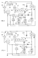
FIG.1 is a circuit block diagram of a combustion and emergency starting control system with auxiliary power -
FIG.2 is an operational diagram showing the variation of battery voltage and motor starting voltage inFIG.1 -
FIG.3 is a circuit diagram of the auxiliary power electric energy starting the engine inFIG.1 -
FIG.4 is a circuit block diagram omitting a secondary charging and discharging auxiliary power storage device and isolation diode inFIG.1 -
FIG.5 is an operational diagram showing the variation of battery voltage and motor starting voltage inFIG.4 -
FIG. 6 is a circuit diagram of the auxiliary power electric energy starting the engine inFIG. 4 -
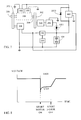
FIG. 7 is the circuit diagram of the direct current boosted boost circuit device of the present invention -
FIG. 8 is an operational diagram showing the variation of battery voltage and motor starting voltage inFIG. 7 -
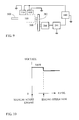
FIG. 9 is a circuit diagram formed by the application of the present invention on a manually started engine with the installation of a direct current boosted boost circuit device -
FIG. 10 is a schematic diagram showing the variation of the direct current boosted boost circuit device output voltage inFIG. 9 -
- 100 :
- Engine set
- 101 :
- Starting motor
- 102 :
- Relay
- 103 :
- Starting switch
- 104 :
- Starting battery
- 105 :
- Isolation diode
- 106 :
- Primary charging and discharging auxiliary power storage device
- 107 :
- Secondary charging and discharging auxiliary power storage device
- 108 :
- Isolation diode
- 109 :
- Engine ignition device
- 110 :
- Fuel injection device
- 200 :
- Generator
- 201 :
- Regulating device
- 300 :
- Engine rotating shaft
- 301
- , 302 : Transmission device
- 500 :
- Emergency starting switching device
- 600 :
- Direct current boosted boost circuit device
- 1051 ,
- 1053 : Diodes
- The present invention relates to a combustion and emergency starting control system with auxiliary power that relies on the installation of an auxiliary power storage device that exclusively supplies the required electric energy to the ignition device or fuel injection device and for emergency starts, and on the installation of isolation diode to isolate battery power for starting motor, in order to prevent the sudden drop of the voltage of the ignition device or the fuel injection device that can hinder normal engine start due to the substantial drop of battery voltage as a result of the greater current required in starting motor when the engine is started while ensuring excellent ignition. Furthermore, the system is equipped with emergency
starting switch device 500 and/or direct current boostedboost circuit device 600 so that when starting battery power is insufficient during starting, the electric energy of the auxiliary battery can drive the starting motor in order to start the engine by means of operating the emergency starting switching device; and that the voltage boost of the direct current boostedboost circuit device 600 will enable the ignition device or the fuel injection device to step up voltage in order to strengthen its starting capability when the motor is started to start the engine. - Furthermore, for application on manually started engine that are not installed with starting motor and starting battery, the installation of a direct current boosted
boost circuit device 600 can provide normal working voltage and ensure excellent ignition at the starting stage when engine speed is relatively low and generator voltage is insufficient. - As shown in
FIG. 1 , a combustion and emergency starting control system with auxiliary power that relies on the installation of an auxiliary power storage device that exclusively supplies the required electric energy to the engine ignition device and/or fuel injection device and for emergency starts, and on the installation of isolation diode to isolate the starting battery of the motor, and on the installation of emergencystarting switching device 500 and/or direct current boostedboost circuit device 600. Its main components include: - - Engine set 100: Consists of internal combustion engine using diesel, biodiesel, gasoline, natural gas or methanol as fuel and equipped with a starting
motor 101; - - Engine rotating shaft 300: Supply rotating kinetic energy engine output to drive loads, and to couple with the starting
motor 101 by means of thetransmission device 301, directly or by means of thetransmission device 302 to couple with the generator set 200; - - Starting motor 101: Consists of brush or brushless direct current or alternating current motors or generators with motor capability. By operating the
motor start relay 102, the battery electric energy is controlled to drive the startingmotor 101, directly or through thetransmission device 301 affecting the generator set 100; - - Starting switch 103: Consists of electromechanical switching elements or solid state electronic switching elements to supply and control power from starting
battery 104 to the ignition device or the ignition device and/or thefuel injection device 110; and/or to supply power and controlmotor starting relay 102; or to directly supply power andcontrol staring motor 101; and/or to supply power to other car electrical devices; - - Starting battery 104: Consists of various charging and discharging secondary batteries or super capacitance to provide electric energy to the starting
motor 101, and to accept power charging from the generated electric energy of thegenerator 200 and external sources; - - Isolation diode 105: Consists of diodes and installed between starting
battery 104 and the primary charging and discharging auxiliarypower storage device 106 to become one way turn-on for startingbattery 104 current to charge the primary charging and discharging auxiliarypower storage device 106. Moreover, theisolation diode 105 is relied upon to prevent reverse discharging to the startingbattery 104; - - Primary charging and discharging auxiliary power storage device 106: Consists of various charging and discharging batteries or super capacitance to store electric energy from the starting
motor 104, built-ingenerator 200 or from other external charging devices; - - Secondary charging and discharging auxiliary power storage device 107: Consists of a secondary charging and discharging battery or super capacitance to store electrical energy from the primary charging and discharging auxiliary
power storage device 106 in order to supply instant electric energy to theengine ignition device 109 during engine ignition; - - Isolation diode 108: Located between the primary charging and discharging auxiliary
power storage device 106 and the secondary charging and discharging auxiliarypower storage device 107, and the current direction from the primary charging and discharging auxiliarypower storage device 106 to the secondary charging and discharging auxiliarypower storage device 107 is in series with theisolation diode 108 in order to prevent reverse discharge by the secondary charging and discharging auxiliarypower storage device 107 on the primary charging and dischargingdevice 106 when using the primary charging and discharging auxiliarypower storage device 106 as the power source in starting the motor in an emergency while operating the emergencystarting switching device 500; - - Generator 200: Consists of alternating current or direct current generator and driven directly or indirectly through
transmission device 302 by an engine to produce a relative alternating electric energy or a rectified direct current or to directly produce direct current electric energy output; whengenerator 200 and/or regulatingdevice 201 are direct current generators and do not possess reverse current avoidance function, isolation is made according to the charging current direction from the generator winding of the generator to the startingbattery 104 through the regulatingdevice 201 and by the forward series installation ofdiode 1051, and ifgenerator 200 possesses reverse current avoidance function, then installingdiode 1051 is unnecessary; - - Regulating device 201: Consists of electromechanical or solid state electronic type circuit device; when
generator 200 works as a direct current generator, the regulating device directly regulates the direct current electric energy and separately charges the startingbattery 104, and/or the primary charging and discharging auxiliarypower storage device 106, and/or secondary charging and discharging auxiliarypower storage device 107, and/or to supply power to other loads, and whengenerator 200 works as an alternating current generator, the alternating current must first be rectified into direct current and then passed through regulatingdevice 201 before it can charge the startingbattery 104, and/or primary charging and discharging auxiliarypower storage device 106, and/or secondary charging and discharging auxiliarypower storage device 107, and/or to supply power to other loads; - - Engine ignition device 109: Consists of electromechanical circuit elements or solid state electronic circuit elements or the combination of both elements to provide ignition to an internal combustion engine for running the engine;
- - Fuel injection device 110: Consists of a fuel injection structural device with throttle switching function to control injection width, and circuit control devices for operating fuel injection structural devices that are able to refer to throttle opening, oil temperature, air intake temperature, and oxygen-containing crankshaft signals (IP-ARB);
- Any one or both of the
engine ignition device 109 and thefuel injection device 110 are installed. - Any one or both of the emergency
starting switching device 500 and the direct current boostedboost circuit device 600 are installed. These include: - - Emergency starting switching device 500: Consists of three-terminal type solid state electronic switching device or mechanical switching device, and the common C terminal is the positive power terminal leading to the
motor starting relay 102 and startingswitch 103, and the normally closed A terminal is the positive terminal leading to the startingbattery 104, and the normally opened B terminal which is switch able to closed during an emergency is the positive terminal leading to the primary charging and discharging auxiliarypower storage device 106; when battery starting power is insufficient, operating the auxiliary switching device can enable the auxiliary battery electric energy to drive and start the motor which in turn will start the engine. - - Direct current boosted boost device 600: Consists of solid state electronic circuit elements or electromechanical circuit elements installed between the power mains of the secondary charging and discharging auxiliary
power storage device 107 and the power mains of theengine ignition device 109 and thefuel injection device 110, and the direct current boostedboost circuit device 600 is started by the signal from therelay 102 when the motor power is turned on to increase voltage in order to enable theengine ignition device 109 or thefuel injection device 110 to run on a booster state advantageous to starting the engine and thediode 1053 is connected in parallel between the power input terminal of the direct current boostedboost circuit device 600 and the higher homopolar voltage output terminal; when the direct current boostedboost circuit device 600 stops operating, electric energy from the power terminal are delivered through thediode 1053 to theengine ignition device 109 and thefuel injection device 110. - During the application of the combustion and emergency starting control system with auxiliary power, the primary charging and discharging auxiliary
power storage device 106 can select elements with a higher energy density while the secondary charging and discharging auxiliarypower storage device 107 can select elements with a higher power density to match ignition quality and economy. - As described in
FIG. 1 , theengine ignition device 109,fuel injection device 110, startingbattery 104,isolation diode 105, primary charging and discharging auxiliarypower storage device 106,isolation diode 108, secondary charging and discharging auxiliarypower storage device 107, emergencystarting switching device 500,generator 200, regulatingdevice 201, direct current boostedboost circuit device 600 are separately installed or combined by two or more of the aforementioned components. -
FIG. 2 is an operational diagram showing the variation of the battery voltage and the motor start voltage inFIG. 1 . As shown inFIG. 2 , the voltage V106 is the terminal voltage of the primary charging and discharging auxiliarypower storage device 106, and Voltage V107 is the terminal voltage of the secondary charging and discharging auxiliarypower storage device 107, and V104 is the terminal voltage of the startingmotor 104, and V600 is the output voltage of the direct current boostedboost circuit device 600. -
FIG 3 is a circuit diagram of the auxiliary power electric energy starting the engine inFIG. 1 . - Moreover, the present invention of a combustion and emergency starting control system with auxiliary power is further configured as shown in the operational circuit block diagram
FIG. 4 omitting the secondary charging and discharging auxiliarypower storage device 107 and theisolation diode 108 inFIG. 1 . i.e., the secondary charging and discharging auxiliarypower storage device 107 andisolation diode 108 inFIG. 1 are omitted and not installed. Instead,isolation diode 105 is forward series installed between the startingbattery 104 and the primary charging and discharging auxiliarypower storage device 106 to become one way turn-on in order to restrict electric charging energy from the startingbattery 104 to the primary charging and discharging auxiliarypower storage device 106. The electric energy required by theengine ignition device 109 and thefuel injection device 110 is then supplied by the primary charging and discharging auxiliarypower storage device 106. When the power of the startingbattery 104 is insufficient, the electric energy of the primary charging and discharging auxiliarypower storage device 106 is used to drive and start the motor and the engine by operating the emergencystarting switching device 500. - Both or any one of the emergency
starting switching device 500 and/or the direct current boostedboost circuit device 600 are installed which shall include: - -- Emergency starting switching device 500: Consists of three-terminal type solid state electronic switching device or mechanical switching device, and the common C terminal is the positive power terminal leading to the
motor starting relay 102 and startingswitch 103, and the normally closed A terminal is the positive terminal leading to the startingbattery 104, and the normally opened B terminal which is switch able to closed during an emergency is the positive terminal leading to the primary charging and discharging auxiliarypower storage device 106; when battery starting power is insufficient, operating the auxiliary switching device can enable the auxiliary battery electric energy to drive and start the motor which in turn will start the engine. - -- Direct current boosted boost device 600: Consists of solid state electronic circuit elements or electromechanical circuit elements installed at the positive power terminal of the secondary charging and discharging auxiliary
power storage device 107 and between the power terminals of theengine ignition device 109 and thefuel injection device 110, and the direct current boostedboost circuit device 600 is started by the signal fromrelay 102 when the motor power is turned on to increase voltage in order to enable theengine ignition device 109 or thefuel injection 110 to run on a booster state advantageous to starting the engine, and thediode 1053 is connected in parallel between the power input terminal of the direct current boostedboost circuit device 600 and the higher homopolar voltage output terminal; when the direct current boostedboost circuit device 600 stops operating, electric energy from the power terminal are delivered throughdiode 1053 to theengine ignition device 109 and thefuel injection device 110. -
FIG. 5 is an operational diagram showing the variation of the battery voltage and the motor start voltage inFIG. 4 . As shown inFIG. 5 , Voltage V106 is the terminal voltage of the primary charging and discharging auxiliarypower storage device 106, and V104 is the terminal voltage of the startingmotor 104, and V600 is the output voltage of the direct current boostedboost circuit device 600. -
FIG. 6 is the circuit diagram of the auxiliary power electric energy starting the engine inFIG. 4 . - As shown in
FIG. 4 , theengine ignition device 109,fuel injection device 110, startingbattery 104, primary charging and discharging auxiliarypower storage device 106, emergencystarting switching device 500,generator 200, regulatingdevice 201 and direct current boostedboost circuit device 600 are separately installed or combined by two or more of the aforementioned components. -
FIG. 7 is the circuit diagram of the direct current boosted boost circuit device of the present invention. -
FIG. 8 is an operational diagram showing the variation of the battery voltage and the motor start voltage inFIG. 7 - As shown in
FIG. 7 , the secondary charging and discharging auxiliarypower storage device 107,isolation diode 108, primary charging and discharging auxiliarypower storage device 106,isolation diode 105, and the emergencystarting switching device 500 inFIG. 1 are omitted and not installed. Instead, the startingbattery 104 is allowed to directly charge the direct current boostedboost circuit device 600. The main components include: - - Engine set 100: Consists of internal combustion engine using diesel, biodiesel, gasoline, natural gas or methanol as fuel;
- - Engine rotating shaft 300: Supply rotating kinetic energy engine output to drive loads, and to couple with the starting
motor 101 by means of thetransmission device 301, directly or by means of thetransmission device 302 to couple with the generator set 200; - - Starting motor 101: Consists of brush or brushless direct current or alternating current motors or generators with motor capability. By operating the
motor start relay 102, the battery electric energy is controlled to drive the startingmotor 101, directly or through thetransmission device 301 affecting the generator set 100; - - Starting switch 103: Consists of electromechanical switching elements or solid state electronic switching elements to supply and control power from starting
battery 104 to the ignition device or the ignition device and/or thefuel injection device 110; and/or to supply power and controlmotor starting relay 102; or to directly supply power andcontrol staring motor 101; and/or to supply power to other car electrical devices; - -Starting battery 104: Consists of various charging and discharging secondary batteries or super capacitance to provide electric energy to the starting
motor 101; and to accept electric energy generated by thegenerator 200 and external power charging. - - Generator 200: Consists of alternating current or direct current generator and driven directly or indirectly through
transmission device 302 by an engine to produce a relative alternating electric energy or a rectified direct current or to directly produce direct current electric energy output; whengenerator 200 and/or regulatingdevice 201 are direct current generators and do not possess reverse current avoidance function, isolation is made according to the charging current direction from the generator winding of the generator to the startingbattery 104 through the regulatingdevice 201 and by the forward series installation ofdiode 1051, and ifgenerator 200 possesses reverse current avoidance function, then installingdiode 1051 is unnecessary. - -Regulating device 201: Consists of electromechanical or solid state electronic type circuit device. When
generator 200 works as a direct current generator, the regulating device directly regulates the direct current electric energy and separately charges the startingbattery 104, and/or to supply power to other loads. Whengenerator 200 works as an alternating current generator, the alternating current must first be rectified into direct current and then passed through regulatingdevice 201 before it can charge the startingbattery 104, and/or to supply power to other loads. - - Engine ignition device 109: Consists of electromechanical circuit elements or solid state electronic circuit elements or the combination of both elements to provide ignition to an internal combustion engine for running the engine;
- - Fuel injection device 110: Consists of a fuel injection structural device with throttle switching function to control injection width, and circuit control devices for operating fuel injection structural devices that are able to refer to throttle opening, oil temperature, air intake temperature, and oxygen-containing crankshaft signals (IP-ARB);
Any one or both of theengine ignition device 109 and thefuel injection device 110 are installed; - -Direct current boosted boost device 600: Consists of solid state electronic circuit elements or electromechanical circuit elements and driven by the power of the starting
battery 104,engine ignition device 109 and thefuel injection device 110, and the direct current boostedboost circuit device 600 is started by the signal fromrelay 102 when the motor power is turned on to increase voltage in order to enable theengine ignition device 109 or thefuel injection device 110 to run on a booster state advantageous to starting the engine, and thediode 1053 is connected in parallel between the power input terminal of the direct current boostedboost circuit device 600 and the higher homopolar voltage output terminal; when the direct current boostedboost circuit device 600 stops operating, electric energy from the power terminal are delivered throughdiode 1053 to theengine ignition device 109 and thefuel injection device 110. -
FIG. 8 is the operational diagram showing the variation of the battery voltage and motor start voltage inFIG. 7 . Voltage V106 inFIG. 8 is the terminal voltage of the primary charging and discharging auxiliarypower storage device 106 while V600 is the output voltage of the boostedboost circuit device 600. -
Engine ignition device 109,fuel injection device 110, startingbattery 104,generator 200, regulatingdevice 201, and direct current boostedboost circuit device 600 inFIG. 7 are separately installed or combined by two or more of the aforementioned components. - If the engine in operational diagram
FIG. 9 is manually started, and because it is not equipped with startingmotor 101, startingbattery 104 andisolation diode 105, power is supplied solely by thegenerator 200 winding and theregulating device 201. So when the manually started engine speed is relatively slow and thegenerator 200 voltage is low, the generated electric energy of thegenerator 200 is stepped up by means of the direct current boostedboost circuit device 600. And during normal operation, the generated electric energy is stepped down to normal voltage in order to improve the operation of theengine ignition device 109 and/or thefuel injection device 110. Methods for checking normal operation include: - (1) Check reference on engine speed signals;
- (2) Refer to generator voltage;
- (3) By setting the transfer to normal voltage when the step up start time expires.
-
FIG. 9 is the circuit diagram formed by the application of the present invention on a manually started engine with the installation of a direct current boosted boost circuit device. -
FIG. 10 is an operational diagram showing the variation of the direct current boosted boost circuit device output voltage inFIG. 9 . - The
ignition device 109,fuel injection device 110,generator 200, regulatingdevice 201 and the direct current boostedboost circuit device 600 are separately installed or combined by two or more of the aforementioned components.
Claims (9)
- A combustion and emergency starting control system with auxiliary power that relies on the installation of an auxiliary power storage device that exclusively supplies the required electric energy to the ignition device or fuel injection device and for emergency starts, and on the installation of isolation diode to isolate battery power for starting motor, in order to prevent the sudden drop of the voltage of the ignition device or the fuel injection device that can hinder normal engine start due to the substantial drop of battery voltage as a result of the greater current required in starting motor when the engine is started while ensuring excellent ignition. Furthermore, the system is equipped with emergency starting switch device (500) and/or direct current boosted boost circuit device (600) so that when starting battery power is insufficient during starting, the electric energy of the auxiliary battery can drive the starting motor in order to start the engine by means of operating the emergency starting switching device; and that the voltage boost of the direct current boosted boost circuit device (600) will enable the ignition device or the fuel injection device to step up voltage in order to strengthen its starting capability when the motor is started to start the engine.
- A combustion and emergency starting control system with auxiliary power as claimed in Claim 1, wherein that includes the installation of an auxiliary power device that exclusively supplies the required electric energy to the engine ignition device and/or fuel injection device and for emergency starts; and the installation of the isolation diode to isolate the starting battery of the motor, and the installation of emergency starting switching device (500) and/or direct current boosted boost circuit device (600), and the main components are:- - engine set (100): consists of internal combustion engine using diesel, biodiesel, gasoline, natural gas or methanol as fuel and equipped with a starting motor (101);- - engine rotating shaft (300): supply rotating kinetic energy engine output to drive loads, and to couple with the starting motor (101) by means of the transmission device (301), directly or by means of the transmission device (302) to couple with the generator set (200);- - starting motor (101): consists of brush or brushless direct current or alternating current motors or generators with motor capability, and by operating the motor start relay (102), the battery electric energy is controlled to drive the starting motor (101), directly or through the transmission device (301) affecting the generator set (100);- - starting switch (103): consists of electromechanical switching elements or solid state electronic switching elements to supply and control power from starting battery (104) to the ignition device or the ignition device and/or the fuel injection device (110); and/or to supply power and control motor starting relay (102); or to directly supply power and control staring motor (101); and/or to supply power to other car electrical devices;- - starting battery (104): consists of various charging and discharging secondary batteries or super capacitance to provide electric energy to the starting motor (101), and to accept power charging from the generated electric energy of the generator (200) and external sources;- - isolation diode (105): consists of diodes and installed between starting battery (104) and the primary charging and discharging auxiliary power storage device (106) to become one way turn-on for starting battery (104) current to charge the primary charging and discharging auxiliary power storage device (106). Moreover, the isolation diode (105) is relied upon to prevent reverse discharging to the starting battery (104);- - primary charging and discharging auxiliary power storage device (106): consists of various charging and discharging batteries or super capacitance to store electric energy from the starting motor (104), built-in generator (200) or from other external charging devices;- - secondary charging and discharging auxiliary power storage device (107): consists of a secondary charging and discharging battery or super capacitance to store electrical energy from the primary charging and discharging auxiliary power storage device (106) in order to supply instant electric energy to the engine ignition device (109) during engine ignition;- - isolation diode (108): located between the primary charging and discharging auxiliary power storage device (106) and the secondary charging and discharging auxiliary power storage device (107), and the current direction from the primary charging and discharging auxiliary power storage device (106) to the secondary charging and discharging auxiliary power storage device (107) is in series with the isolation diode (108) in order to prevent reverse discharge by the secondary charging and discharging auxiliary power storage device (107) on the primary charging and discharging auxiliary power storage device (106) when using the primary charging and discharging auxiliary power storage device (106) as the power source in starting the motor in an emergency while operating the emergency starting switching device (500);- - generator (200): consists of alternating current or direct current generator and driven directly or indirectly through transmission device (302) by an engine to produce a relative alternating electric energy or a rectified direct current or to directly produce direct current electric energy output; when generator (200) and/or regulating device (201) are direct current generators and do not possess reverse current avoidance function, isolation is made according to the charging current direction from the generator winding of the generator to the starting battery (104) through the regulating device (201) and by the forward series installation of diode (1051), and if generator (200) possesses reverse current avoidance function, then installing diode (1051) is unnecessary;- - regulating device (201): consists of electromechanical or solid state electronic type circuit device; when generator (200) works as a direct current generator, the regulating device directly regulates the direct current electric energy and separately charges the starting battery (104), and/or the primary charging and discharging auxiliary power storage device (106), and/or secondary charging and discharging auxiliary power storage device (107), and/or to supply power to other loads; and when generator (200) works as an alternating current generator, the alternating current must first be rectified into direct current and then passed through regulating device (201) before it can charge the starting battery (104), and/or primary charging and discharging auxiliary power storage device (106), and/or secondary charging and discharging auxiliary power storage device (107), and/or to supply power to other loads;- - engine ignition device (109): consists of electromechanical circuit elements or solid state electronic circuit elements or the combination of both elements to provide ignition to an internal combustion engine for running the engine;- - fuel injection device (110): consists of a fuel injection structural device with throttle switching function to control injection width, and circuit control devices for operating fuel injection structural devices that are able to refer to throttle opening, oil temperature, air intake temperature, and oxygen-containing crankshaft signals (IP-ARB);
any one or both of the engine ignition device (109) and the fuel injection device (110) are installed;
any one or both of the emergency starting switching device (500) and the direct current boosted boost circuit device (600) are installed, and these include:- - emergency starting switching device (500): consists of three-terminal type solid state electronic switching device or mechanical switching device, and the common C terminal is the positive power terminal leading to the motor starting relay (102) and starting switch (103), and the normally closed A terminal is the positive terminal leading to the starting battery (104), and the normally opened B terminal which is switch able to closed during an emergency is the positive terminal leading to the primary charging and discharging auxiliary power storage device (106); when battery starting power is insufficient, operating the auxiliary switching device can enable the auxiliary battery electric energy to drive and start the motor which in turn will start the engine;- - direct current boosted boost device (600): consists of solid state electronic circuit elements or electromechanical circuit elements installed between the power mains of the secondary charging and discharging auxiliary power storage device (107) and the power mains of the engine ignition device (109) and the fuel injection device (110), and direct current boosted boost circuit device (600) is started by the signal from the relay (102) when the motor power is turned on to increase voltage in order to enable the engine ignition device (109) or the fuel injection device (110) to run on a booster state advantageous to starting the engine, and diode (1053) is connected in parallel between the power input terminal of the direct current boosted boost circuit device (600) and the higher homopolar voltage output terminal; when the direct current boosted boost circuit device (600) stops operating, electric energy from the power terminal are delivered through the diode (1053) to the engine ignition device (109) and the fuel injection device (110). - A combustion and emergency starting control system with auxiliary power as claimed in Claim 2, wherein the engine ignition device (109), fuel injection device (110), starting battery (104), isolation diode (105), primary charging and discharging auxiliary power storage device (106), isolation diode (108), secondary charging and discharging auxiliary power storage device (107), emergency starting switching device (500), generator (200), regulating device (201) and direct current boosted boost circuit device (600) are separately installed or combined by two or more of the aforementioned components.
- A combustion and emergency starting control system with auxiliary power as claimed in Claim 2, wherein the secondary charging and discharging auxiliary power storage device (107) and isolation diode (108) omitted and uninstalled; instead, isolation diode (105) is forward series installed between the starting battery (104) and the primary charging and discharging auxiliary power storage device (106) to become one way turn-on in order to restrict electric charging energy from the starting battery (104) to the primary charging and discharging auxiliary power storage device (106). The electric energy required by the engine ignition device (109) and the fuel injection device (110) is then supplied by the primary charging and discharging auxiliary power storage device (106). When the power of the starting battery (104) is insufficient, the electric energy of the primary charging and discharging auxiliary power storage device (106) is used to drive and start the motor, and in turn, start the engine by operating the emergency starting switching device (500);
both or any one of the emergency starting switching device (500) and/or the direct current boosted boost circuit device (600) are installed which shall include:- - emergency starting switching device (500): consists of three-terminal type solid state electronic switching device or mechanical switching device, and the common C terminal is the positive power terminal leading to the motor starting relay (102) and starting switch (103), and the normally closed A terminal is the positive terminal leading to the starting battery (104), and the normally opened B terminal which is switch able to closed during an emergency is the positive terminal leading to the primary charging and discharging auxiliary power storage device (106); when battery starting power is insufficient, operating the auxiliary switching device can enable the auxiliary battery electric energy to drive and start the motor which in turn will start the engine;- - direct current boosted boost device (600): consists of solid state electronic circuit elements or electromechanical circuit elements installed at the positive power terminal of the secondary charging and discharging auxiliary power storage device (107) and between the power terminals of the engine ignition device (109) and the fuel injection device (110), and the direct current boosted boost circuit device (600) is started by the signal from relay (102) when the motor power is turned on to increase voltage in order to enable the engine ignition device (109) or the fuel injection device (110) to run on a booster state advantageous to starting the engine, and the diode (1053) is connected in parallel between the power input terminal of the direct current boosted boost circuit device (600) and the higher homopolar voltage output terminal; when the direct current boosted boost circuit device (600) stops operating, electric energy from the power terminal are delivered through diode (1053) to the engine ignition device (109) and the fuel injection device (110). - A combustion and emergency starting control system with auxiliary
power as claimed in Claim 4, wherein the ignition device (109), fuel injection device (110), starting battery (104), primary charging and discharging auxiliary power storage device (106), emergency starting switching device (500), generator (200), regulating device (210) and direct current boosted boost circuit device (600) are separately installed or combined by two or more of the aforementioned components. - A combustion and emergency starting control system with auxiliary power as claimed in Claim 2, wherein the secondary charging and discharging auxiliary power storage device (107), isolation diode (108), primary charging and discharging powers storage device (106), isolation diode (105) and emergency starting switching device (500) are omitted and not installed; power is instead supplied directly to the direct current boosted boost circuit device (600) from the starting battery (104), and the main components are:- - engine set (100): consists of internal combustion engine using diesel, biodiesel, gasoline, natural gas or methanol as fuel;- - engine rotating shaft (300): supply rotating kinetic energy engine output to drive loads, and to couple with the starting motor (101) by means of the transmission device (301), directly or by means of the transmission device (302) to couple with the generator set (200);- - starting motor (101): consists of brush or brushless direct current or alternating current motors or generators with motor capability and by operating the motor start relay (102), the battery electric energy is controlled to drive the starting motor (101), directly or through the transmission device (301) affecting the generator set (100);- - starting switch (103): consists of electromechanical switching elements or solid state electronic switching elements to supply and control power from starting battery (104) to the ignition device or the ignition device and/or the fuel injection device (110); and/or to supply power and control motor starting relay (102); or to directly supply power and control staring motor (101); and/or to supply power to other car electrical devices;- -starting battery (104): consists of various charging and discharging secondary batteries or super capacitance to provide electric energy to the starting motor (101); and to accept electric energy generated by the generator (200) and external power charging;- - generator (200): consists of alternating current or direct current generator and driven directly or indirectly through transmission device (302) by an engine to produce a relative alternating electric energy or a rectified direct current or to directly produce direct current electric energy output; when generator (200) and/or regulating device (201) are direct current generators and do not possess reverse current avoidance function, isolation is made according to the charging current direction from the generator winding to the generator to the starting battery (104) through the regulating device (201) and by the forward series installation of diode (1051) and if generator (200) possesses reverse current avoidance function, then installing diode (1051) is unnecessary;- -regulating device (201): consists of electromechanical or solid state electronic type circuit device, and when generator (200) works as a direct current generator, the regulating device directly regulates the direct current electric energy and separately charges the starting battery (104), and/or to supply power to other loads; when generator (200) works as an alternating current generator, the alternating current must first be rectified into direct current and then passed through regulating device (201) before it can charge the starting battery (104), and/or to supply power to other loads;- - engine ignition device (109): consists of electromechanical circuit elements or solid state electronic circuit elements or the combination of both elements to provide ignition to an internal combustion engine for running the engine;- - fuel injection device (110): consists of a fuel injection structural device with throttle switching function to control injection width, and circuit control devices for operating fuel injection structural devices that are able to refer to throttle opening, oil temperature, air intake temperature, and oxygen-containing crankshaft signals (IP-ARB);
any one or both of the engine ignition device (109) and the fuel injection device (110) are installed;- -direct current boosted boost device (600): consists of solid state electronic circuit elements or electromechanical circuit elements and driven by the power of the starting battery (104), engine ignition device (109) and the fuel injection device (110), and the direct current boosted boost circuit device (600) is started by the signal from relay (102) when the motor power is turned on to increase voltage in order to enable the engine ignition device (109) or the fuel injection device (110) to run on a booster state advantageous to starting the engine, and the diode (1053) is connected in parallel between the power input terminal of the direct current boosted boost circuit device (600) and the higher homopolar voltage output terminal; when the direct current boosted boost circuit device (600) stops operating, electric energy from the power terminal are delivered through diode (1053) to the engine ignition device (109) and the fuel injection device (110). - A combustion and emergency starting control system with auxiliary power as claimed in Claim 6, wherein the engine ignition device (109), fuel injection device (110), starting battery (104), generator (200), regulating device (201), and direct current boosted boost circuit device (600) are separately installed or combined by two or more of the aforementioned components.
- A combustion and emergency starting control system with auxiliary power with a manually started engine, wherein it is not equipped with starting motor (101), starting battery (104) and isolation diode (105), power is supplied solely by the generator (200) winding and the regulating device (201) to the direct current boosted boost circuit device (600) ; so when the manually started engine speed is relatively slow and the generator (200) voltage is low, the generated electric energy of the generator (200) is stepped up by means of the direct current boosted boost circuit device (600). And during normal operation, the generated electric energy is stepped down to normal voltage in order to improve the operation of the engine ignition device (109) and/or the fuel injection device (110), and methods for checking normal operation include:1) Check reference on engine speed signals;2) Refer to generator voltage;3) By setting the transfer to normal voltage when the step up start time expires.
- A combustion and emergency starting control system with auxiliary power as claimed in Claim 8, wherein the ignition device (109), fuel injection device (110), generator (200), regulating device (201) and direct current boosted boost circuit device (600) are separately installed or combined by two or more of the aforementioned components.
Applications Claiming Priority (1)
| Application Number | Priority Date | Filing Date | Title |
|---|---|---|---|
| US12/457,715 US7938092B2 (en) | 2009-06-19 | 2009-06-19 | Combustion and emergency starting control system with auxiliary power |
Publications (3)
| Publication Number | Publication Date |
|---|---|
| EP2282046A2 true EP2282046A2 (en) | 2011-02-09 |
| EP2282046A3 EP2282046A3 (en) | 2011-03-16 |
| EP2282046B1 EP2282046B1 (en) | 2019-12-04 |
Family
ID=42635046
Family Applications (1)
| Application Number | Title | Priority Date | Filing Date |
|---|---|---|---|
| EP10166263.3A Active EP2282046B1 (en) | 2009-06-19 | 2010-06-17 | Combustion and emergency starting control system with auxiliary power |
Country Status (5)
| Country | Link |
|---|---|
| US (1) | US7938092B2 (en) |
| EP (1) | EP2282046B1 (en) |
| JP (1) | JP2011017337A (en) |
| CN (3) | CN201966682U (en) |
| TW (2) | TWI571562B (en) |
Cited By (1)
| Publication number | Priority date | Publication date | Assignee | Title |
|---|---|---|---|---|
| EP2282047A3 (en) * | 2009-06-19 | 2018-04-04 | Tai-Her Yang | Split-type auxiliary power combustion and emergency starting system |
Families Citing this family (23)
| Publication number | Priority date | Publication date | Assignee | Title |
|---|---|---|---|---|
| US7878177B2 (en) * | 2007-10-23 | 2011-02-01 | Ford Global Technologies, Llc | Internal combustion engine having common power source for ion current sensing and fuel injectors |
| US7938092B2 (en) * | 2009-06-19 | 2011-05-10 | Tai-Her Yang | Combustion and emergency starting control system with auxiliary power |
| DE102009027407A1 (en) * | 2009-07-01 | 2011-01-05 | Robert Bosch Gmbh | Method for operating a starter control, computer program product and starter control |
| CN102155342B (en) * | 2011-03-04 | 2012-12-12 | 广州金升阳科技有限公司 | Power supply circuit for automobile |
| JP5619806B2 (en) * | 2012-03-21 | 2014-11-05 | 古河電気工業株式会社 | Secondary battery state detection device and secondary battery state detection method |
| CA2830695C (en) | 2012-10-22 | 2020-09-08 | Techtronic Outdoor Products Technology Limited | Double source battery charger |
| CN104097585B (en) * | 2013-04-11 | 2016-12-28 | 比亚迪股份有限公司 | For the emergency starting device of automobile and the emergency starting method of automobile and automobile |
| CN103321814B (en) * | 2013-06-09 | 2015-09-09 | 深圳市民展科技开发有限公司 | Car emergency ignition installation |
| US20140375067A1 (en) * | 2013-06-19 | 2014-12-25 | Tai-Her Yang | Combustion and emergency start controlling device with separated-type auxiliary power source and system thereof |
| US20140375066A1 (en) * | 2013-06-19 | 2014-12-25 | Tai-Her Yang | Combustion and emergency start controlling device having auxiliary power source and system thereof |
| DK3263886T3 (en) * | 2015-02-26 | 2021-09-13 | Gestima Solar S L | Apparatus and method for managing charging and discharging of ultracapacitors without control wiring |
| CN107404147A (en) * | 2016-05-20 | 2017-11-28 | 北京汽车股份有限公司 | Automobile and its emergency starting TRT |
| CN106812649A (en) * | 2016-12-30 | 2017-06-09 | 常州格力博有限公司 | Startor of internal combustion engine and its startup method |
| KR102417380B1 (en) * | 2017-04-12 | 2022-07-06 | 현대자동차주식회사 | Apparatus and Method for controlling start sequence of an engine in a vehicle |
| US9809123B1 (en) * | 2017-07-24 | 2017-11-07 | Premergy, Inc. | Control schemes and intelligent battery selection for electric vehicles |
| US10017056B1 (en) * | 2017-09-10 | 2018-07-10 | Premergy, Inc. | Electric vehicles with removable homopolar generators for increased driving distances |
| US10749354B2 (en) | 2017-09-10 | 2020-08-18 | Premergy, Inc. | Intelligent circuit control for solar panel systems |
| US20190226441A1 (en) * | 2018-01-24 | 2019-07-25 | MTU Onsite Energy Corporation | Generator set startup using renewable energy |
| CN109474050A (en) * | 2018-11-14 | 2019-03-15 | 上海广为美线电源电器有限公司 | Multifunctional charger with car assisted starting |
| US11319915B2 (en) | 2020-06-11 | 2022-05-03 | Kohler Co. | Engine system, and method of starting the engine |
| RU2745851C1 (en) * | 2020-07-29 | 2021-04-02 | Федеральное государственное казенное военное образовательное учреждение высшего образования "Военный учебно-научный центр Военно-воздушных сил "Военно-воздушная академия имени профессора Н.Е. Жуковского и Ю.А. Гагарина" (г. Воронеж) Министерства обороны Российской Федерации | Autonomous power unit for starting internal combustion engines |
| JP7454469B2 (en) * | 2020-08-18 | 2024-03-22 | 株式会社Subaru | vehicle power system |
| CN113771618A (en) * | 2021-09-07 | 2021-12-10 | 徐州徐工随车起重机有限公司 | Vehicle-mounted direct current motor power system and control method |
Family Cites Families (23)
| Publication number | Priority date | Publication date | Assignee | Title |
|---|---|---|---|---|
| US2075431A (en) * | 1935-02-07 | 1937-03-30 | Laney Floyd M Du | Ignition booster system |
| US2529921A (en) * | 1946-05-06 | 1950-11-14 | Davolt Elton | Starter booster |
| US2521969A (en) * | 1948-02-28 | 1950-09-12 | Thomas L Dugan | Electrical booster starting system |
| US3516396A (en) * | 1963-10-29 | 1970-06-23 | Harry Wibur Lawson Jr | Electronic ignition system |
| JPS5138018B1 (en) * | 1968-01-30 | 1976-10-19 | ||
| FR2330872A1 (en) * | 1973-03-08 | 1977-06-03 | Schlumberger Compteurs | Electric circuit for starter for helicopter gas turbine - includes two batteries which are connected either in series or in parallel |
| US4127782A (en) * | 1975-09-18 | 1978-11-28 | Sawafuji Electric Co., Ltd. | Automotive power supply |
| JPH02101933A (en) * | 1988-10-07 | 1990-04-13 | Teruo Hayashi | Method and apparatus for protecting engine-starting auxiliary battery |
| JPH02259277A (en) * | 1989-03-31 | 1990-10-22 | Isuzu Motors Ltd | Engine starter device |
| US5325042A (en) * | 1993-01-29 | 1994-06-28 | Allied Signal Inc. | Turbine engine start system with improved starting characteristics |
| JP3859105B2 (en) * | 1998-09-25 | 2006-12-20 | 株式会社デンソー | Hybrid vehicle charger |
| US6321707B1 (en) * | 1998-11-12 | 2001-11-27 | James Dunn | Multifunction auxiliary vehicle power and starter system |
| TWI242625B (en) * | 2001-11-23 | 2005-11-01 | Tai-Her Yang | Ignition system having auxiliary power supply isolated from main system |
| JP3812459B2 (en) * | 2002-02-26 | 2006-08-23 | トヨタ自動車株式会社 | Vehicle power supply control device |
| JP4209640B2 (en) * | 2002-07-03 | 2009-01-14 | 新電元工業株式会社 | Boost power supply for engine generator |
| JP2005042584A (en) * | 2003-07-25 | 2005-02-17 | Toyota Motor Corp | Fuel supply system for liquefied gas engine |
| JP4378224B2 (en) * | 2004-06-04 | 2009-12-02 | 株式会社ミクニ | Power supply |
| JP2006094594A (en) * | 2004-09-22 | 2006-04-06 | Nsk Ltd | In-vehicle motor control device, electric power steering device and electric brake device using the same |
| JP4466309B2 (en) * | 2004-10-12 | 2010-05-26 | 株式会社デンソー | Engine start assist system |
| US7325524B2 (en) * | 2005-02-02 | 2008-02-05 | Tai-Her Yang | Ignition/fuel injection system with auxiliary and separation charging power sources |
| US7963264B2 (en) * | 2008-06-25 | 2011-06-21 | GM Global Technology Operations LLC | Engine cranking system and method |
| JP5246407B2 (en) * | 2008-11-04 | 2013-07-24 | 株式会社ジェイテクト | Motor drive circuit and electric power steering device |
| US7938092B2 (en) * | 2009-06-19 | 2011-05-10 | Tai-Her Yang | Combustion and emergency starting control system with auxiliary power |
-
2009
- 2009-06-19 US US12/457,715 patent/US7938092B2/en not_active Expired - Fee Related
-
2010
- 2010-06-10 CN CN2010202216099U patent/CN201966682U/en not_active Expired - Lifetime
- 2010-06-10 CN CN201410218009.XA patent/CN104005896A/en active Pending
- 2010-06-10 CN CN201010196937.2A patent/CN101931263B/en not_active Expired - Fee Related
- 2010-06-15 JP JP2010135883A patent/JP2011017337A/en active Pending
- 2010-06-17 EP EP10166263.3A patent/EP2282046B1/en active Active
- 2010-06-18 TW TW099119920A patent/TWI571562B/en not_active IP Right Cessation
- 2010-06-18 TW TW099211616U patent/TWM416888U/en unknown
Non-Patent Citations (1)
| Title |
|---|
| None |
Cited By (1)
| Publication number | Priority date | Publication date | Assignee | Title |
|---|---|---|---|---|
| EP2282047A3 (en) * | 2009-06-19 | 2018-04-04 | Tai-Her Yang | Split-type auxiliary power combustion and emergency starting system |
Also Published As
| Publication number | Publication date |
|---|---|
| TW201100629A (en) | 2011-01-01 |
| CN101931263A (en) | 2010-12-29 |
| EP2282046B1 (en) | 2019-12-04 |
| US7938092B2 (en) | 2011-05-10 |
| US20100319646A1 (en) | 2010-12-23 |
| CN104005896A (en) | 2014-08-27 |
| JP2011017337A (en) | 2011-01-27 |
| EP2282046A3 (en) | 2011-03-16 |
| CN201966682U (en) | 2011-09-07 |
| TWI571562B (en) | 2017-02-21 |
| TWM416888U (en) | 2011-11-21 |
| CN101931263B (en) | 2015-01-14 |
Similar Documents
| Publication | Publication Date | Title |
|---|---|---|
| EP2282046B1 (en) | Combustion and emergency starting control system with auxiliary power | |
| US8667942B2 (en) | Split-type auxiliary power combustion and emergency starting system | |
| EP2816222A2 (en) | Combustion and emergency start controlling device with separated-type auxiliary power source and system thereof | |
| JP6410392B2 (en) | Control device and system for combustion and emergency starting with auxiliary power supply | |
| US20180083469A1 (en) | High power density jump starter | |
| US6684839B2 (en) | Ignition or fuel injection control system with auxiliary source | |
| US7325524B2 (en) | Ignition/fuel injection system with auxiliary and separation charging power sources | |
| US20130000585A1 (en) | Starter supply network | |
| AU2020453568B2 (en) | Engine generator |
Legal Events
| Date | Code | Title | Description |
|---|---|---|---|
| PUAI | Public reference made under article 153(3) epc to a published international application that has entered the european phase |
Free format text: ORIGINAL CODE: 0009012 |
|
| AK | Designated contracting states |
Kind code of ref document: A2 Designated state(s): AL AT BE BG CH CY CZ DE DK EE ES FI FR GB GR HR HU IE IS IT LI LT LU LV MC MK MT NL NO PL PT RO SE SI SK SM TR |
|
| AX | Request for extension of the european patent |
Extension state: BA ME RS |
|
| PUAL | Search report despatched |
Free format text: ORIGINAL CODE: 0009013 |
|
| AK | Designated contracting states |
Kind code of ref document: A3 Designated state(s): AL AT BE BG CH CY CZ DE DK EE ES FI FR GB GR HR HU IE IS IT LI LT LU LV MC MK MT NL NO PL PT RO SE SI SK SM TR |
|
| AX | Request for extension of the european patent |
Extension state: BA ME RS |
|
| 17P | Request for examination filed |
Effective date: 20110909 |
|
| STAA | Information on the status of an ep patent application or granted ep patent |
Free format text: STATUS: EXAMINATION IS IN PROGRESS |
|
| 17Q | First examination report despatched |
Effective date: 20170927 |
|
| RIC1 | Information provided on ipc code assigned before grant |
Ipc: G01R 31/36 20190101ALI20190228BHEP Ipc: F02N 99/00 20100101ALI20190228BHEP Ipc: F02N 11/08 20060101ALI20190228BHEP Ipc: F02N 11/10 20060101AFI20190228BHEP Ipc: F02N 11/14 20060101ALI20190228BHEP Ipc: F02D 41/06 20060101ALN20190228BHEP |
|
| RIC1 | Information provided on ipc code assigned before grant |
Ipc: F02N 11/14 20060101ALI20190301BHEP Ipc: F02N 11/10 20060101AFI20190301BHEP Ipc: F02N 99/00 20100101ALI20190301BHEP Ipc: F02N 11/08 20060101ALI20190301BHEP Ipc: G01R 31/36 20190101ALI20190301BHEP Ipc: F02D 41/06 20060101ALN20190301BHEP |
|
| RIC1 | Information provided on ipc code assigned before grant |
Ipc: F02D 41/06 20060101ALN20190507BHEP Ipc: G01R 31/36 20190101ALI20190507BHEP Ipc: F02N 11/14 20060101ALI20190507BHEP Ipc: F02N 11/10 20060101AFI20190507BHEP Ipc: F02N 99/00 20100101ALI20190507BHEP Ipc: F02N 11/08 20060101ALI20190507BHEP |
|
| GRAP | Despatch of communication of intention to grant a patent |
Free format text: ORIGINAL CODE: EPIDOSNIGR1 |
|
| STAA | Information on the status of an ep patent application or granted ep patent |
Free format text: STATUS: GRANT OF PATENT IS INTENDED |
|
| INTG | Intention to grant announced |
Effective date: 20190614 |
|
| GRAS | Grant fee paid |
Free format text: ORIGINAL CODE: EPIDOSNIGR3 |
|
| GRAA | (expected) grant |
Free format text: ORIGINAL CODE: 0009210 |
|
| STAA | Information on the status of an ep patent application or granted ep patent |
Free format text: STATUS: THE PATENT HAS BEEN GRANTED |
|
| AK | Designated contracting states |
Kind code of ref document: B1 Designated state(s): AL AT BE BG CH CY CZ DE DK EE ES FI FR GB GR HR HU IE IS IT LI LT LU LV MC MK MT NL NO PL PT RO SE SI SK SM TR |
|
| REG | Reference to a national code |
Ref country code: GB Ref legal event code: FG4D |
|
| REG | Reference to a national code |
Ref country code: CH Ref legal event code: EP |
|
| REG | Reference to a national code |
Ref country code: AT Ref legal event code: REF Ref document number: 1209722 Country of ref document: AT Kind code of ref document: T Effective date: 20191215 |
|
| REG | Reference to a national code |
Ref country code: DE Ref legal event code: R096 Ref document number: 602010062220 Country of ref document: DE |
|
| REG | Reference to a national code |
Ref country code: IE Ref legal event code: FG4D |
|
| REG | Reference to a national code |
Ref country code: NL Ref legal event code: MP Effective date: 20191204 |
|
| REG | Reference to a national code |
Ref country code: LT Ref legal event code: MG4D |
|
| PG25 | Lapsed in a contracting state [announced via postgrant information from national office to epo] |
Ref country code: FI Free format text: LAPSE BECAUSE OF FAILURE TO SUBMIT A TRANSLATION OF THE DESCRIPTION OR TO PAY THE FEE WITHIN THE PRESCRIBED TIME-LIMIT Effective date: 20191204 Ref country code: BG Free format text: LAPSE BECAUSE OF FAILURE TO SUBMIT A TRANSLATION OF THE DESCRIPTION OR TO PAY THE FEE WITHIN THE PRESCRIBED TIME-LIMIT Effective date: 20200304 Ref country code: LV Free format text: LAPSE BECAUSE OF FAILURE TO SUBMIT A TRANSLATION OF THE DESCRIPTION OR TO PAY THE FEE WITHIN THE PRESCRIBED TIME-LIMIT Effective date: 20191204 Ref country code: SE Free format text: LAPSE BECAUSE OF FAILURE TO SUBMIT A TRANSLATION OF THE DESCRIPTION OR TO PAY THE FEE WITHIN THE PRESCRIBED TIME-LIMIT Effective date: 20191204 Ref country code: NO Free format text: LAPSE BECAUSE OF FAILURE TO SUBMIT A TRANSLATION OF THE DESCRIPTION OR TO PAY THE FEE WITHIN THE PRESCRIBED TIME-LIMIT Effective date: 20200304 Ref country code: ES Free format text: LAPSE BECAUSE OF FAILURE TO SUBMIT A TRANSLATION OF THE DESCRIPTION OR TO PAY THE FEE WITHIN THE PRESCRIBED TIME-LIMIT Effective date: 20191204 Ref country code: GR Free format text: LAPSE BECAUSE OF FAILURE TO SUBMIT A TRANSLATION OF THE DESCRIPTION OR TO PAY THE FEE WITHIN THE PRESCRIBED TIME-LIMIT Effective date: 20200305 Ref country code: LT Free format text: LAPSE BECAUSE OF FAILURE TO SUBMIT A TRANSLATION OF THE DESCRIPTION OR TO PAY THE FEE WITHIN THE PRESCRIBED TIME-LIMIT Effective date: 20191204 |
|
| PG25 | Lapsed in a contracting state [announced via postgrant information from national office to epo] |
Ref country code: HR Free format text: LAPSE BECAUSE OF FAILURE TO SUBMIT A TRANSLATION OF THE DESCRIPTION OR TO PAY THE FEE WITHIN THE PRESCRIBED TIME-LIMIT Effective date: 20191204 |
|
| PG25 | Lapsed in a contracting state [announced via postgrant information from national office to epo] |
Ref country code: AL Free format text: LAPSE BECAUSE OF FAILURE TO SUBMIT A TRANSLATION OF THE DESCRIPTION OR TO PAY THE FEE WITHIN THE PRESCRIBED TIME-LIMIT Effective date: 20191204 |
|
| PG25 | Lapsed in a contracting state [announced via postgrant information from national office to epo] |
Ref country code: EE Free format text: LAPSE BECAUSE OF FAILURE TO SUBMIT A TRANSLATION OF THE DESCRIPTION OR TO PAY THE FEE WITHIN THE PRESCRIBED TIME-LIMIT Effective date: 20191204 Ref country code: NL Free format text: LAPSE BECAUSE OF FAILURE TO SUBMIT A TRANSLATION OF THE DESCRIPTION OR TO PAY THE FEE WITHIN THE PRESCRIBED TIME-LIMIT Effective date: 20191204 Ref country code: RO Free format text: LAPSE BECAUSE OF FAILURE TO SUBMIT A TRANSLATION OF THE DESCRIPTION OR TO PAY THE FEE WITHIN THE PRESCRIBED TIME-LIMIT Effective date: 20191204 Ref country code: PT Free format text: LAPSE BECAUSE OF FAILURE TO SUBMIT A TRANSLATION OF THE DESCRIPTION OR TO PAY THE FEE WITHIN THE PRESCRIBED TIME-LIMIT Effective date: 20200429 |
|
| PG25 | Lapsed in a contracting state [announced via postgrant information from national office to epo] |
Ref country code: SM Free format text: LAPSE BECAUSE OF FAILURE TO SUBMIT A TRANSLATION OF THE DESCRIPTION OR TO PAY THE FEE WITHIN THE PRESCRIBED TIME-LIMIT Effective date: 20191204 Ref country code: IS Free format text: LAPSE BECAUSE OF FAILURE TO SUBMIT A TRANSLATION OF THE DESCRIPTION OR TO PAY THE FEE WITHIN THE PRESCRIBED TIME-LIMIT Effective date: 20200404 Ref country code: SK Free format text: LAPSE BECAUSE OF FAILURE TO SUBMIT A TRANSLATION OF THE DESCRIPTION OR TO PAY THE FEE WITHIN THE PRESCRIBED TIME-LIMIT Effective date: 20191204 |
|
| REG | Reference to a national code |
Ref country code: DE Ref legal event code: R097 Ref document number: 602010062220 Country of ref document: DE |
|
| REG | Reference to a national code |
Ref country code: AT Ref legal event code: MK05 Ref document number: 1209722 Country of ref document: AT Kind code of ref document: T Effective date: 20191204 |
|
| PLBE | No opposition filed within time limit |
Free format text: ORIGINAL CODE: 0009261 |
|
| STAA | Information on the status of an ep patent application or granted ep patent |
Free format text: STATUS: NO OPPOSITION FILED WITHIN TIME LIMIT |
|
| PG25 | Lapsed in a contracting state [announced via postgrant information from national office to epo] |
Ref country code: DK Free format text: LAPSE BECAUSE OF FAILURE TO SUBMIT A TRANSLATION OF THE DESCRIPTION OR TO PAY THE FEE WITHIN THE PRESCRIBED TIME-LIMIT Effective date: 20191204 |
|
| 26N | No opposition filed |
Effective date: 20200907 |
|
| PG25 | Lapsed in a contracting state [announced via postgrant information from national office to epo] |
Ref country code: SI Free format text: LAPSE BECAUSE OF FAILURE TO SUBMIT A TRANSLATION OF THE DESCRIPTION OR TO PAY THE FEE WITHIN THE PRESCRIBED TIME-LIMIT Effective date: 20191204 Ref country code: AT Free format text: LAPSE BECAUSE OF FAILURE TO SUBMIT A TRANSLATION OF THE DESCRIPTION OR TO PAY THE FEE WITHIN THE PRESCRIBED TIME-LIMIT Effective date: 20191204 Ref country code: PL Free format text: LAPSE BECAUSE OF FAILURE TO SUBMIT A TRANSLATION OF THE DESCRIPTION OR TO PAY THE FEE WITHIN THE PRESCRIBED TIME-LIMIT Effective date: 20191204 |
|
| REG | Reference to a national code |
Ref country code: DE Ref legal event code: R119 Ref document number: 602010062220 Country of ref document: DE |
|
| PG25 | Lapsed in a contracting state [announced via postgrant information from national office to epo] |
Ref country code: CZ Free format text: LAPSE BECAUSE OF NON-PAYMENT OF DUE FEES Effective date: 20200617 Ref country code: MC Free format text: LAPSE BECAUSE OF FAILURE TO SUBMIT A TRANSLATION OF THE DESCRIPTION OR TO PAY THE FEE WITHIN THE PRESCRIBED TIME-LIMIT Effective date: 20191204 |
|
| REG | Reference to a national code |
Ref country code: CH Ref legal event code: PL |
|
| GBPC | Gb: european patent ceased through non-payment of renewal fee |
Effective date: 20200617 |
|
| PG25 | Lapsed in a contracting state [announced via postgrant information from national office to epo] |
Ref country code: LU Free format text: LAPSE BECAUSE OF NON-PAYMENT OF DUE FEES Effective date: 20200617 |
|
| REG | Reference to a national code |
Ref country code: BE Ref legal event code: MM Effective date: 20200630 |
|
| PG25 | Lapsed in a contracting state [announced via postgrant information from national office to epo] |
Ref country code: IE Free format text: LAPSE BECAUSE OF NON-PAYMENT OF DUE FEES Effective date: 20200617 Ref country code: LI Free format text: LAPSE BECAUSE OF NON-PAYMENT OF DUE FEES Effective date: 20200630 Ref country code: CH Free format text: LAPSE BECAUSE OF NON-PAYMENT OF DUE FEES Effective date: 20200630 Ref country code: GB Free format text: LAPSE BECAUSE OF NON-PAYMENT OF DUE FEES Effective date: 20200617 Ref country code: FR Free format text: LAPSE BECAUSE OF NON-PAYMENT OF DUE FEES Effective date: 20200630 |
|
| PG25 | Lapsed in a contracting state [announced via postgrant information from national office to epo] |
Ref country code: BE Free format text: LAPSE BECAUSE OF NON-PAYMENT OF DUE FEES Effective date: 20200630 Ref country code: DE Free format text: LAPSE BECAUSE OF NON-PAYMENT OF DUE FEES Effective date: 20210101 |
|
| PG25 | Lapsed in a contracting state [announced via postgrant information from national office to epo] |
Ref country code: IT Free format text: LAPSE BECAUSE OF NON-PAYMENT OF DUE FEES Effective date: 20200617 |
|
| PG25 | Lapsed in a contracting state [announced via postgrant information from national office to epo] |
Ref country code: TR Free format text: LAPSE BECAUSE OF FAILURE TO SUBMIT A TRANSLATION OF THE DESCRIPTION OR TO PAY THE FEE WITHIN THE PRESCRIBED TIME-LIMIT Effective date: 20191204 Ref country code: MT Free format text: LAPSE BECAUSE OF FAILURE TO SUBMIT A TRANSLATION OF THE DESCRIPTION OR TO PAY THE FEE WITHIN THE PRESCRIBED TIME-LIMIT Effective date: 20191204 Ref country code: CY Free format text: LAPSE BECAUSE OF FAILURE TO SUBMIT A TRANSLATION OF THE DESCRIPTION OR TO PAY THE FEE WITHIN THE PRESCRIBED TIME-LIMIT Effective date: 20191204 |
|
| PG25 | Lapsed in a contracting state [announced via postgrant information from national office to epo] |
Ref country code: MK Free format text: LAPSE BECAUSE OF FAILURE TO SUBMIT A TRANSLATION OF THE DESCRIPTION OR TO PAY THE FEE WITHIN THE PRESCRIBED TIME-LIMIT Effective date: 20191204 |