EP2282031A1 - Filtering device with integrated bypass for an air inlet - Google Patents
Filtering device with integrated bypass for an air inlet Download PDFInfo
- Publication number
- EP2282031A1 EP2282031A1 EP09400033A EP09400033A EP2282031A1 EP 2282031 A1 EP2282031 A1 EP 2282031A1 EP 09400033 A EP09400033 A EP 09400033A EP 09400033 A EP09400033 A EP 09400033A EP 2282031 A1 EP2282031 A1 EP 2282031A1
- Authority
- EP
- European Patent Office
- Prior art keywords
- filtering device
- mobile part
- ring
- filtering
- fixed part
- Prior art date
- Legal status (The legal status is an assumption and is not a legal conclusion. Google has not performed a legal analysis and makes no representation as to the accuracy of the status listed.)
- Granted
Links
- 238000001914 filtration Methods 0.000 title claims abstract description 80
- 238000006073 displacement reaction Methods 0.000 claims description 7
- 239000000463 material Substances 0.000 claims description 6
- 229920000742 Cotton Polymers 0.000 claims description 5
- 230000003213 activating effect Effects 0.000 claims description 3
- 230000004888 barrier function Effects 0.000 description 10
- 238000004519 manufacturing process Methods 0.000 description 3
- 239000000428 dust Substances 0.000 description 2
- 238000013519 translation Methods 0.000 description 2
- 229920000049 Carbon (fiber) Polymers 0.000 description 1
- XAGFODPZIPBFFR-UHFFFAOYSA-N aluminium Chemical compound [Al] XAGFODPZIPBFFR-UHFFFAOYSA-N 0.000 description 1
- 229910052782 aluminium Inorganic materials 0.000 description 1
- 239000004411 aluminium Substances 0.000 description 1
- 239000004917 carbon fiber Substances 0.000 description 1
- 230000004064 dysfunction Effects 0.000 description 1
- 238000012423 maintenance Methods 0.000 description 1
- VNWKTOKETHGBQD-UHFFFAOYSA-N methane Chemical compound C VNWKTOKETHGBQD-UHFFFAOYSA-N 0.000 description 1
- 238000012986 modification Methods 0.000 description 1
- 230000004048 modification Effects 0.000 description 1
- 238000012797 qualification Methods 0.000 description 1
- 230000000717 retained effect Effects 0.000 description 1
- 238000009420 retrofitting Methods 0.000 description 1
- 239000004576 sand Substances 0.000 description 1
- 238000012360 testing method Methods 0.000 description 1
Images

Classifications
-
- F—MECHANICAL ENGINEERING; LIGHTING; HEATING; WEAPONS; BLASTING
- F02—COMBUSTION ENGINES; HOT-GAS OR COMBUSTION-PRODUCT ENGINE PLANTS
- F02C—GAS-TURBINE PLANTS; AIR INTAKES FOR JET-PROPULSION PLANTS; CONTROLLING FUEL SUPPLY IN AIR-BREATHING JET-PROPULSION PLANTS
- F02C7/00—Features, components parts, details or accessories, not provided for in, or of interest apart form groups F02C1/00 - F02C6/00; Air intakes for jet-propulsion plants
- F02C7/04—Air intakes for gas-turbine plants or jet-propulsion plants
- F02C7/05—Air intakes for gas-turbine plants or jet-propulsion plants having provisions for obviating the penetration of damaging objects or particles
- F02C7/055—Air intakes for gas-turbine plants or jet-propulsion plants having provisions for obviating the penetration of damaging objects or particles with intake grids, screens or guards
-
- B—PERFORMING OPERATIONS; TRANSPORTING
- B01—PHYSICAL OR CHEMICAL PROCESSES OR APPARATUS IN GENERAL
- B01D—SEPARATION
- B01D46/00—Filters or filtering processes specially modified for separating dispersed particles from gases or vapours
- B01D46/0027—Filters or filtering processes specially modified for separating dispersed particles from gases or vapours with additional separating or treating functions
- B01D46/0035—Filters or filtering processes specially modified for separating dispersed particles from gases or vapours with additional separating or treating functions by wetting, e.g. using surfaces covered with oil
-
- B—PERFORMING OPERATIONS; TRANSPORTING
- B01—PHYSICAL OR CHEMICAL PROCESSES OR APPARATUS IN GENERAL
- B01D—SEPARATION
- B01D46/00—Filters or filtering processes specially modified for separating dispersed particles from gases or vapours
- B01D46/0084—Filters or filtering processes specially modified for separating dispersed particles from gases or vapours provided with safety means
- B01D46/0087—Bypass or safety valves
-
- B—PERFORMING OPERATIONS; TRANSPORTING
- B01—PHYSICAL OR CHEMICAL PROCESSES OR APPARATUS IN GENERAL
- B01D—SEPARATION
- B01D46/00—Filters or filtering processes specially modified for separating dispersed particles from gases or vapours
- B01D46/24—Particle separators, e.g. dust precipitators, using rigid hollow filter bodies
- B01D46/2403—Particle separators, e.g. dust precipitators, using rigid hollow filter bodies characterised by the physical shape or structure of the filtering element
- B01D46/2411—Filter cartridges
-
- B—PERFORMING OPERATIONS; TRANSPORTING
- B01—PHYSICAL OR CHEMICAL PROCESSES OR APPARATUS IN GENERAL
- B01D—SEPARATION
- B01D46/00—Filters or filtering processes specially modified for separating dispersed particles from gases or vapours
- B01D46/42—Auxiliary equipment or operation thereof
- B01D46/44—Auxiliary equipment or operation thereof controlling filtration
- B01D46/46—Auxiliary equipment or operation thereof controlling filtration automatic
-
- B—PERFORMING OPERATIONS; TRANSPORTING
- B64—AIRCRAFT; AVIATION; COSMONAUTICS
- B64D—EQUIPMENT FOR FITTING IN OR TO AIRCRAFT; FLIGHT SUITS; PARACHUTES; ARRANGEMENT OR MOUNTING OF POWER PLANTS OR PROPULSION TRANSMISSIONS IN AIRCRAFT
- B64D33/00—Arrangement in aircraft of power plant parts or auxiliaries not otherwise provided for
- B64D33/02—Arrangement in aircraft of power plant parts or auxiliaries not otherwise provided for of combustion air intakes
-
- F—MECHANICAL ENGINEERING; LIGHTING; HEATING; WEAPONS; BLASTING
- F02—COMBUSTION ENGINES; HOT-GAS OR COMBUSTION-PRODUCT ENGINE PLANTS
- F02C—GAS-TURBINE PLANTS; AIR INTAKES FOR JET-PROPULSION PLANTS; CONTROLLING FUEL SUPPLY IN AIR-BREATHING JET-PROPULSION PLANTS
- F02C7/00—Features, components parts, details or accessories, not provided for in, or of interest apart form groups F02C1/00 - F02C6/00; Air intakes for jet-propulsion plants
- F02C7/04—Air intakes for gas-turbine plants or jet-propulsion plants
- F02C7/057—Control or regulation
-
- B—PERFORMING OPERATIONS; TRANSPORTING
- B01—PHYSICAL OR CHEMICAL PROCESSES OR APPARATUS IN GENERAL
- B01D—SEPARATION
- B01D2273/00—Operation of filters specially adapted for separating dispersed particles from gases or vapours
- B01D2273/14—Filters which are moved between two or more positions, e.g. by turning, pushing
-
- B—PERFORMING OPERATIONS; TRANSPORTING
- B01—PHYSICAL OR CHEMICAL PROCESSES OR APPARATUS IN GENERAL
- B01D—SEPARATION
- B01D2279/00—Filters adapted for separating dispersed particles from gases or vapours specially modified for specific uses
- B01D2279/60—Filters adapted for separating dispersed particles from gases or vapours specially modified for specific uses for the intake of internal combustion engines or turbines
-
- B—PERFORMING OPERATIONS; TRANSPORTING
- B64—AIRCRAFT; AVIATION; COSMONAUTICS
- B64C—AEROPLANES; HELICOPTERS
- B64C27/00—Rotorcraft; Rotors peculiar thereto
- B64C27/04—Helicopters
-
- B—PERFORMING OPERATIONS; TRANSPORTING
- B64—AIRCRAFT; AVIATION; COSMONAUTICS
- B64D—EQUIPMENT FOR FITTING IN OR TO AIRCRAFT; FLIGHT SUITS; PARACHUTES; ARRANGEMENT OR MOUNTING OF POWER PLANTS OR PROPULSION TRANSMISSIONS IN AIRCRAFT
- B64D33/00—Arrangement in aircraft of power plant parts or auxiliaries not otherwise provided for
- B64D33/02—Arrangement in aircraft of power plant parts or auxiliaries not otherwise provided for of combustion air intakes
- B64D2033/0246—Arrangement in aircraft of power plant parts or auxiliaries not otherwise provided for of combustion air intakes comprising particle separators
-
- F—MECHANICAL ENGINEERING; LIGHTING; HEATING; WEAPONS; BLASTING
- F05—INDEXING SCHEMES RELATING TO ENGINES OR PUMPS IN VARIOUS SUBCLASSES OF CLASSES F01-F04
- F05D—INDEXING SCHEME FOR ASPECTS RELATING TO NON-POSITIVE-DISPLACEMENT MACHINES OR ENGINES, GAS-TURBINES OR JET-PROPULSION PLANTS
- F05D2220/00—Application
- F05D2220/30—Application in turbines
- F05D2220/32—Application in turbines in gas turbines
- F05D2220/329—Application in turbines in gas turbines in helicopters
Definitions
- the present invention relates to the technical field of inlet barrier filters on engines or on auxiliary power units with radial air intake.
- Aircrafts or helicopters often have engines, for example turbo-shaft engines with a ring-shaped inlet barrier filter surrounding and covering a radial air intake.
- the ring-shaped filters were used only on auxiliary power units with radial air intake, since it was not possible to integrate a bypass system on a radial air intake and since a clogging of the barrier filter on the auxiliary power unit was not critical with respect of the safety of the aircraft.
- Integrating a bypass system in an air intake channel is associated with disadvantages when used in aircraft, in particular in helicopters, because both, the channel and the bypass system should be as compact as possible in order to reduce as much as possible their space requirement. This can very easily lead to an increase in conception, manufacturing and fabrication costs.
- the closing unit is a cylindrical and movable tube with an opening which is set either facing the filtering inlet or facing the non filtering inlet.
- a filtering device for an engine or a power unit with a radial air intake comprising a ring-shaped filter for covering the radial air intake, characterised in that the ring-shaped filter comprises a first fixed part and a second mobile part, comprising each a rigid frame in which a filtering material is inserted and affixed, the second mobile part being movable with respect of the first fixed part through actuator means, from a filtering position in which the whole radial air intake is covered by the ring-shaped filter, to a bypass position in which the second mobile part uncovers at least partly the radial air intake.
- the first fixed part and second mobile part form each a half of the ring-shaped filter.
- the second mobile part is sliding along the first fixed part in its displacement from the filtering position to the bypass position.
- the second mobile part has a greater diameter than the diameter of the first fixed part and is sliding on an outer side or face of the first fixed part.
- the second mobile part has a smaller diameter than the diameter of the first fixed part and is sliding on the inner side or face of the first fixed part.
- the second mobile part is sliding along a portion of a circular path.
- the second mobile part is sliding along a portion of a straight path in the longitudinal direction of the ring-shaped filter in its displacement from the filtering position to the bypass position.
- each part of the ring-shaped filter comprises a rigid frame containing filtering material such as cotton.
- the filtering material comprises for example several layers of cotton between two mashed grids.
- the grids are for example made of aluminium and the frame is for example made of carbon fiber.
- the cotton can be impregnated with oil.
- the actuator means comprise electrical and/or mechanical means, such as an electrical or hydraulically motor or linear actuator.
- the second mobile part can be set in its bypass position. This would enhance the performance of the engine of the aircraft.
- the second mobile part can be set in its filtering position. The displacement of the second mobile part is preferably driven automatically.
- the filtering device comprises retaining and sliding means which ensure the retaining and the sliding of the second mobile part with respect of the first fixed part.
- an engine such as a turbo-shaft engine, comprising a filtering device according to the invention.
- auxiliary power unit for example in an aircraft, comprising a filtering device according to the invention.
- the objects of the invention are also met by a helicopter in which a filtering device according to the invention is installed.
- the safety of the aircraft is improved because although if a clogging of the inlet barrier filter of the engine occurs, the aircraft has still the possibility, without any loss of power, to reach its goal, where a maintenance operation can be engaged.
- a filtering device provides a ring-shaped inlet barrier filter with a bypass system.
- the filtering device can easily be adapted to different existing turbo-shaft engines with radial air intake.
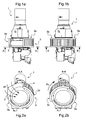
- Figure 1a is a view of an example of a filtering device according to the invention, which is mounted on an engine 1.
- the engine 1 of the turbo-shaft type, has a radial air intake 2.
- the filtering device comprises a ring-shaped filter 3 which covers the radial air intake 2.
- This ring-shaped filter 3 is an inlet barrier filter on the engine 1.
- the ring-shaped filter 3 comprises a first fixed part 3a and a second mobile part 3b which is movable with respect of the first fixed part 3a through actuator means.
- the second mobile part 3b is movable from a filtering position, illustrated in figures 1b and 2b , in which the whole radial air intake 2 is covered by the ring-shaped filter 3, to a bypass position, illustrated in figures 1a and 2a , in which the second mobile part 3b uncovers at least partly the radial air intake 2.
- the engine 1 provides the fixing support for the second fixed part 3b.
- the bypass position is shown for example in the figures 1a, 2a , 3a and 4 while the filtering position is shown in figures 1b, 2b , 3b and 5 .
- Figure 2a is a perspective and part-view of the filtering device of figure 1a , in particular according to the section A-A.
- the second mobile part 3b has slit along the first fixed part 3a during its displacement from the filtering position to the bypass position. In the bypass position, an air flow AF penetrates directly in the engine 1, through the radial air intake 2.
- Figure 2b is a perspective and part-view of the filtering device of figure 1b , in particular according to the section B-B.
- the second mobile part 3b is in its filtering position. In this filtering position, an air flow AF penetrates in the radial air intake 2 through the entire periphery of the ring-shaped filter 3.
- the first fixed part 3a and second mobile part 3b form each a half of the ring-shaped filter 3.
- Each part 3a, 3b of the ring-shaped filter 3 comprises a rigid frame 5a, 5b containing filtering material 4 such as several layers of cotton.
- the second mobile part 3b is sliding along a portion of a circular path Pc, indicated by a corresponding arrow on the drawings.
- the second mobile part 3b has a greater diameter than the diameter of the first fixed part 3a. This allows the second mobile part 3b to slide on an outer side or face of the first fixed part 3a.
- the second mobile part 3b has a smaller diameter than the diameter of the first fixed part 3a. This allows the second mobile part 3 to slide on an inner side or face of the first fixed part 3a.
- the second mobile part 3b is sliding along a portion of a straight path Ps in the longitudinal direction L of the ring-shaped filter 3.
- the longitudinal direction L corresponds to the central axis of the ring-shaped filter 3.
- the straight path Ps is identified by a corresponding arrow on the drawing of figure 4 .
- the second mobile part 3b After a short translation along the longitudinal direction L, the second mobile part 3b, in its bypass position, uncovers the length of the radial air intake 2 which was previously covered by this second mobile part 3b. Consequently, an air flow AF penetrates directly in the engine 1, through the radial air intake 2.
- the filtering device comprises also actuator means for moving, when they are activated, the second mobile part 3b in the bypass position.
- the actuator means comprise electrical and/or mechanical means.
- the actuator means comprise for example an electrical or hydraulically motor 6 which can open the bypass through a least one curved rack 7 on the second mobile part 3b.
- the curved rack 7 cooperates with a least one pinion 8 which is mounted on a driveshaft 9 of the motor 6.
- the second mobile part 3b can then move along the circular path Pc.
- the driveshaft 9 with its two pinions 8 is mounted on a fixed guiding cage 10, through which moves the second mobile part 3b.
- the illustrated example shows the driveshaft 9 with a pinion 8 on each end.
- Each pinion 8 cooperates with a corresponding curved rack 7.
- the second mobile part 3b with its curved racks 7 is retained between the first fixed part 3a and the pinions 8.
- the actuator means could comprise an electrical or hydraulically linear actuator which can push or pull the second mobile part along the straight path Ps.
- the filtering device comprises retaining and sliding means which ensure the retaining and the sliding of the second mobile part with respect of the first fixed part.
- the retaining and sliding means comprise for example two rails (not shown) affixed on the first fixed part along the circular path Pc or along the straight path Ps.
- the retaining function can be achieved in any known manner.
- the retaining function can be achieved by the motor or the linear actuator. Besides the moving, they are also able to hold their position.
- the filtering device comprises sensor means for detecting a total or partly clogged state of the ring-shaped filter 3 and driving means for activating the actuator means as soon as a clogged state or a partly clogged state occurs.
- the driving means are integrated for example in a control unit (not shown).
Landscapes
- Chemical & Material Sciences (AREA)
- Engineering & Computer Science (AREA)
- Combustion & Propulsion (AREA)
- Chemical Kinetics & Catalysis (AREA)
- Mechanical Engineering (AREA)
- General Engineering & Computer Science (AREA)
- Oil, Petroleum & Natural Gas (AREA)
- Physics & Mathematics (AREA)
- Geometry (AREA)
- Aviation & Aerospace Engineering (AREA)
- Filtering Of Dispersed Particles In Gases (AREA)
Abstract
Description
- The present invention relates to the technical field of inlet barrier filters on engines or on auxiliary power units with radial air intake. Aircrafts or helicopters often have engines, for example turbo-shaft engines with a ring-shaped inlet barrier filter surrounding and covering a radial air intake.
- These filters, which are exposed to many different operating and background conditions, in particular in aircrafts, can be clogged after some time of operation of the barrier filter. The power provided by the engine will then fall down, what could lead to a stall of the aircraft. In such a situation, the safety of the aircraft is no more guaranteed.
- It is the reason why in the past, the inlet barrier filters on engines with radial air intake, were installed on the fuselage or in an air intake channel of the vehicle and not directly on the radial air intake of the engine. It was known to integrate a bypass system in such a channel, which would feed the engine with air in case that a clogging of the barrier filters occurs.
- The ring-shaped filters were used only on auxiliary power units with radial air intake, since it was not possible to integrate a bypass system on a radial air intake and since a clogging of the barrier filter on the auxiliary power unit was not critical with respect of the safety of the aircraft.
- Integrating a bypass system in an air intake channel is associated with disadvantages when used in aircraft, in particular in helicopters, because both, the channel and the bypass system should be as compact as possible in order to reduce as much as possible their space requirement. This can very easily lead to an increase in conception, manufacturing and fabrication costs.
- Another disadvantage arises because retrofitting a filter with a bypass system on a fuselage or in an air intake channel of an existing helicopter or aircraft, is a big change on the air intake and usually causes a lot of qualification and certification work.
- It is also known, for example with
document FR 2 906 569 - It is also known, for example with
document FR 2 924 471 - It is the object of the invention to overcome the mentioned disadvantages and to be able to provide a filtering device for engines or power units with radial air intake, which integrates a bypass system and which is located on the radial air intake.
- It is an additional object of the invention to provide a filtering device for engines or power units with radial air intake, which needs a low space requirement in the aircraft.
- It is an additional object of the invention to provide a filtering device for engines or power units with radial air intake, which has a low number of parts, which is cheap, easy to manufacture and to replace.
- These objects are met by a filtering device for an engine or a power unit with a radial air intake, comprising a ring-shaped filter for covering the radial air intake, characterised in that the ring-shaped filter comprises a first fixed part and a second mobile part, comprising each a rigid frame in which a filtering material is inserted and affixed, the second mobile part being movable with respect of the first fixed part through actuator means, from a filtering position in which the whole radial air intake is covered by the ring-shaped filter, to a bypass position in which the second mobile part uncovers at least partly the radial air intake.
- According to one exemplary embodiment of the filtering device according to the invention, the first fixed part and second mobile part form each a half of the ring-shaped filter.
- According to one exemplary embodiment of the filtering device according to the invention, the second mobile part is sliding along the first fixed part in its displacement from the filtering position to the bypass position.
- According to one exemplary embodiment of the filtering device according to the invention, the second mobile part has a greater diameter than the diameter of the first fixed part and is sliding on an outer side or face of the first fixed part.
- According to another exemplary embodiment of the filtering device according to the invention, the second mobile part has a smaller diameter than the diameter of the first fixed part and is sliding on the inner side or face of the first fixed part.
- According to one exemplary embodiment of the filtering device according to the invention, the second mobile part is sliding along a portion of a circular path.
- According to another exemplary embodiment of the filtering device according to the invention, the second mobile part is sliding along a portion of a straight path in the longitudinal direction of the ring-shaped filter in its displacement from the filtering position to the bypass position.
- According to one exemplary embodiment of the filtering device according to the invention, each part of the ring-shaped filter comprises a rigid frame containing filtering material such as cotton. The filtering material comprises for example several layers of cotton between two mashed grids. The grids are for example made of aluminium and the frame is for example made of carbon fiber. To improve the efficiency of the filter, the cotton can be impregnated with oil.
- According to one exemplary embodiment of the filtering device according to the invention, the actuator means comprise electrical and/or mechanical means, such as an electrical or hydraulically motor or linear actuator.
- In a further embodiment of the invention it has been shown to be advantageous if it comprises sensor means for detecting during operation a total or partly clogged state of the ring-shaped filter and driving means for activating the actuator means as soon as a total or partly clogged state occurs or as soon as particular flight conditions arise. In particular flight conditions, when no harmful dust or ice may enter the radial air intake, the second mobile part can be set in its bypass position. This would enhance the performance of the engine of the aircraft. In other flight conditions, such as in a dust or sand environment, for example by landing, the second mobile part can be set in its filtering position. The displacement of the second mobile part is preferably driven automatically.
- According to one exemplary embodiment of the filtering device according to the invention, it comprises retaining and sliding means which ensure the retaining and the sliding of the second mobile part with respect of the first fixed part.
- These objects are also met by an engine, such as a turbo-shaft engine, comprising a filtering device according to the invention.
- These objects are also met by an auxiliary power unit, for example in an aircraft, comprising a filtering device according to the invention.
- The objects of the invention are also met by a helicopter in which a filtering device according to the invention is installed.
- According to the invention the safety of the aircraft is improved because although if a clogging of the inlet barrier filter of the engine occurs, the aircraft has still the possibility, without any loss of power, to reach its goal, where a maintenance operation can be engaged.
- There is a further advantage in that a filtering device according to the invention provides a ring-shaped inlet barrier filter with a bypass system.
- There is a further advantage according to the invention in that the filtering device can easily be adapted to different existing turbo-shaft engines with radial air intake.
- There is a further advantage with the filtering device according to the invention, in that the usual air intake of the engine will be used and in that no modification of the existing air intake needs to be done. This avoids additional certification work, like icing test, while integrating an inlet barrier filter into an existing engine.
- Further advantages, characteristics and details of the invention are set out in the following description of a preferred exemplary embodiment as well as with reference to the drawings, which show the following:
-
Figure 1a , a view of an example of a filtering device mounted on an engine, in particular a filtering device with a mobile part in a bypass position, according to the invention; -
Figure 1b , a view of an example of a filtering device mounted on an engine, in particular a filtering device with a mobile part in a filtering position, according to the invention; -
Figure 2a , a perspective and part-view of the filtering device offigure 1a , in particular according to the section A-A offigure 1a ; -
Figure 2b , a perspective and part-view of the filtering device offigure 1b , in particular according to the section B-B offigure 1b ; -
Figure 3a , a perspective and part-view of the filtering device according to the invention, and with a mobile part in a bypass position; -
Figure 3b , a perspective and part-view of the filtering device according to the invention, and with a mobile part in a filtering position; -
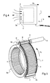
Figure 4 , an illustration of an additional example of a filtering device according to the invention, in particular a filtering device with a mobile part in a bypass position after a translation displacement of the mobile part. - and
Figure 5 , a perspective and part-view of the filtering device according to the invention, showing actuator means, the fixed part and the mobile part of a ring-shaped filter. -
Figure 1a is a view of an example of a filtering device according to the invention, which is mounted on anengine 1. Theengine 1 , of the turbo-shaft type, has aradial air intake 2. - The filtering device according to the invention comprises a ring-
shaped filter 3 which covers theradial air intake 2. This ring-shaped filter 3 is an inlet barrier filter on theengine 1. - The ring-
shaped filter 3 comprises a firstfixed part 3a and a secondmobile part 3b which is movable with respect of the firstfixed part 3a through actuator means. The secondmobile part 3b is movable from a filtering position, illustrated infigures 1b and 2b , in which the wholeradial air intake 2 is covered by the ring-shaped filter 3, to a bypass position, illustrated infigures 1a and 2a , in which the secondmobile part 3b uncovers at least partly theradial air intake 2. Theengine 1 provides the fixing support for the second fixedpart 3b. - The bypass position is shown for example in the
figures 1a, 2a ,3a and4 while the filtering position is shown infigures 1b, 2b ,3b and5 . -
Figure 2a is a perspective and part-view of the filtering device offigure 1a , in particular according to the section A-A. The secondmobile part 3b has slit along the firstfixed part 3a during its displacement from the filtering position to the bypass position. In the bypass position, an air flow AF penetrates directly in theengine 1, through theradial air intake 2. -
Figure 2b is a perspective and part-view of the filtering device offigure 1b , in particular according to the section B-B. The secondmobile part 3b is in its filtering position. In this filtering position, an air flow AF penetrates in theradial air intake 2 through the entire periphery of the ring-shapedfilter 3. - In one embodiment of the invention, the first
fixed part 3a and secondmobile part 3b form each a half of the ring-shapedfilter 3. - Each
part filter 3 comprises arigid frame filtering material 4 such as several layers of cotton. - In the embodiment of the invention shown in
figures 1b, 2b , and3b , the secondmobile part 3b is sliding along a portion of a circular path Pc, indicated by a corresponding arrow on the drawings. - In this respect, in one embodiment of the invention, the second
mobile part 3b has a greater diameter than the diameter of the firstfixed part 3a. This allows the secondmobile part 3b to slide on an outer side or face of the firstfixed part 3a. - In an alternative embodiment of the invention (not shown), the second
mobile part 3b has a smaller diameter than the diameter of the firstfixed part 3a. This allows the secondmobile part 3 to slide on an inner side or face of the firstfixed part 3a. - In another embodiment of the invention, as shown in
figure 4 , the secondmobile part 3b is sliding along a portion of a straight path Ps in the longitudinal direction L of the ring-shapedfilter 3. The longitudinal direction L corresponds to the central axis of the ring-shapedfilter 3. The straight path Ps is identified by a corresponding arrow on the drawing offigure 4 . - After a short translation along the longitudinal direction L, the second
mobile part 3b, in its bypass position, uncovers the length of theradial air intake 2 which was previously covered by this secondmobile part 3b. Consequently, an air flow AF penetrates directly in theengine 1, through theradial air intake 2. - The filtering device according to the invention comprises also actuator means for moving, when they are activated, the second
mobile part 3b in the bypass position. The actuator means comprise electrical and/or mechanical means. The actuator means comprise for example an electrical or hydraulically motor 6 which can open the bypass through a least onecurved rack 7 on the secondmobile part 3b. Thecurved rack 7 cooperates with a least onepinion 8 which is mounted on adriveshaft 9 of the motor 6. The secondmobile part 3b can then move along the circular path Pc. Thedriveshaft 9 with its twopinions 8 is mounted on a fixed guidingcage 10, through which moves the secondmobile part 3b. The illustrated example shows thedriveshaft 9 with apinion 8 on each end. Eachpinion 8 cooperates with a correspondingcurved rack 7. The secondmobile part 3b with itscurved racks 7 is retained between the firstfixed part 3a and thepinions 8. - Alternatively, the actuator means could comprise an electrical or hydraulically linear actuator which can push or pull the second mobile part along the straight path Ps.
- According to one exemplary embodiment of the filtering device according to the invention, it comprises retaining and sliding means which ensure the retaining and the sliding of the second mobile part with respect of the first fixed part. The retaining and sliding means comprise for example two rails (not shown) affixed on the first fixed part along the circular path Pc or along the straight path Ps. The retaining function can be achieved in any known manner. The retaining function can be achieved by the motor or the linear actuator. Besides the moving, they are also able to hold their position.
- In one embodiment of the invention, the filtering device comprises sensor means for detecting a total or partly clogged state of the ring-shaped
filter 3 and driving means for activating the actuator means as soon as a clogged state or a partly clogged state occurs. The driving means are integrated for example in a control unit (not shown). - By means of the sensor and driving means, it is achieved that no dysfunction of the
engine 1 or no decrease in the power furnished by theengine 1 occurs consequently of a total or partly clogging of the ring-shapedfilter 3 during operation. - Of course, within the scope of the invention it is possible to provide still further embodiment options. The invention also covers variants of technical characteristics and that are not described in detail but that suggest themselves to the average person skilled in the art.
Claims (13)
- A filtering device for an engine (1) or a for power unit with a radial air intake (2), comprising a ring-shaped filter (3) for covering the radial air intake (2),
characterised in that the ring-shaped filter (3) comprises a first fixed part (3a) and a second mobile part (3b) comprising each a rigid frame in which a filtering material is inserted and affixed, the rigid frame of the second mobile part (3b) being movable with respect of the first fixed part (3a) through actuator means from a filtering position in which the whole radial air intake (2) is covered by the ring-shaped filter (3), to a bypass position in which the second mobile part (3b) uncovers at least partly the radial air intake (2). - The filtering device according to claim 1,
characterised in that the first fixed part (3a) and second mobile part (3b) form each a half of the ring-shaped filter (3). - The filtering device according to claim 1 or 2,
characterised in that the second mobile part (3b) is sliding along the first fixed part (3) in its displacement from the filtering position to the bypass position. - The filtering device according to claim 3,
characterised in that the second mobile part (2) presents a greater diameter than the diameter of the first fixed part (3a) and is sliding on the outer side or face of the first fixed part (3a). - The filtering device according to claim 3,
characterised in that the second mobile part (3b) has a smaller diameter than the diameter of the first fixed part (3a) and is sliding on the inner side or face of the first fixed part (3a). - The filtering device according to any one of the claims 3 to 5,
characterised in that the second mobile part (3b) is sliding along a portion of a circular path (Pc). - The filtering device according to the claims 1 or 2,
characterised in that the second mobile part (3b) is sliding along a portion of a straight path (Ps) in the longitudinal direction (L) of the ring-shaped filter (3) in its displacement from the filtering position to the bypass position. - The filtering device according to any one of the claims 1 to 7,
characterised in that each part of the ring-shaped filter (3) comprises contains a filtering material (4) such as several layers of cotton. - The filtering device according to any one of the claims 1 to 8,
characterised in that the actuator means comprise electrical and/or mechanical means such as an electrical or hydraulically motor or linear actuator. - The filtering device according to any one of the claims 1 to 9,
characterised in that it comprises retaining and sliding means which ensure the retaining and the sliding of the second mobile part with respect of the first fixed part. - The filtering device according to any one of the claims 1 to 10,
characterised in that it comprises sensor means for detecting during operation a total or partly clogged state of the ring-shaped filter (3) and driving means for activating the actuator means as soon as a total or partly clogged state occurs or as soon as particular flight conditions arise. - An engine, such as a turbo-shaft engine, comprising a filtering device according to any one of the claims 1 to 11,
- An auxiliary power unit, for example in an aircraft, comprising a filtering device according to any one of the claims 1 to 11.
Priority Applications (2)
| Application Number | Priority Date | Filing Date | Title |
|---|---|---|---|
| EP09400033A EP2282031B1 (en) | 2009-07-02 | 2009-07-02 | Filtering device with integrated bypass for an air inlet |
| US12/726,670 US8292978B2 (en) | 2009-07-02 | 2010-03-18 | Radial air intake device with integrated bypass for an air inlet |
Applications Claiming Priority (1)
| Application Number | Priority Date | Filing Date | Title |
|---|---|---|---|
| EP09400033A EP2282031B1 (en) | 2009-07-02 | 2009-07-02 | Filtering device with integrated bypass for an air inlet |
Publications (2)
| Publication Number | Publication Date |
|---|---|
| EP2282031A1 true EP2282031A1 (en) | 2011-02-09 |
| EP2282031B1 EP2282031B1 (en) | 2012-06-06 |
Family
ID=41308054
Family Applications (1)
| Application Number | Title | Priority Date | Filing Date |
|---|---|---|---|
| EP09400033A Not-in-force EP2282031B1 (en) | 2009-07-02 | 2009-07-02 | Filtering device with integrated bypass for an air inlet |
Country Status (2)
| Country | Link |
|---|---|
| US (1) | US8292978B2 (en) |
| EP (1) | EP2282031B1 (en) |
Cited By (6)
| Publication number | Priority date | Publication date | Assignee | Title |
|---|---|---|---|---|
| EP2743178A1 (en) | 2012-12-11 | 2014-06-18 | AIRBUS HELICOPTERS DEUTSCHLAND GmbH | An air inlet combining a filter and a bypass device for use with a turbine engine |
| EP3392144A1 (en) | 2017-04-21 | 2018-10-24 | Bmc S.R.L. | Air intake unit for an aircraft engine and provided with an air filter and with an air filter bypass duct |
| CN112324573A (en) * | 2020-10-29 | 2021-02-05 | 中国航发湖南动力机械研究所 | Aeroengine air inlet cover |
| IT202000008230A1 (en) | 2020-04-17 | 2021-10-17 | Bmc Srl | AIR INTAKE UNIT FOR A VEHICLE ENGINE AND EQUIPPED WITH AN OPENABLE AIR FILTER |
| IT202200015141A1 (en) | 2022-07-19 | 2024-01-19 | Bmc Srl | AIR INTAKE UNIT FOR A VEHICLE POWERTRAIN |
| EP4534826A1 (en) * | 2023-10-05 | 2025-04-09 | Pratt & Whitney Canada Corp. | Variable inlet guard screen for an inlet of an aircraft engine |
Families Citing this family (21)
| Publication number | Priority date | Publication date | Assignee | Title |
|---|---|---|---|---|
| US9192882B2 (en) * | 2009-09-03 | 2015-11-24 | Game Changers Llc | Apparatus and methods using non-fouling bypass filter |
| CN107368705B (en) * | 2011-04-14 | 2021-07-13 | 完整基因有限公司 | Methods and computer systems for analyzing genomic DNA of organisms |
| FR2993862B1 (en) * | 2012-07-30 | 2015-08-21 | Turbomeca | AIR INLET FOR HELICOPTER ENGINE WITH INCREASED BYPASS CIRCULATION |
| WO2014109711A1 (en) * | 2013-01-10 | 2014-07-17 | Heptagon Micro Optics Pte. Ltd. | Opto-electronic modules including features to help reduce stray light and/or optical cross-talk |
| EP2853493B1 (en) * | 2013-09-30 | 2016-08-10 | AIRBUS HELICOPTERS DEUTSCHLAND GmbH | Helicopter with engine air intakes |
| US10364746B2 (en) | 2013-11-04 | 2019-07-30 | United Technologies Corporation | Turbomachinery inlet screen |
| US9441598B2 (en) | 2013-11-08 | 2016-09-13 | Honeywell International Inc. | Aircraft fuel filter impending and actual bypass indication system |
| US20160146511A1 (en) * | 2014-11-24 | 2016-05-26 | Hamilton Sundstrand Corporation | Heat exchanger assembly for aircraft ecs |
| US9719352B2 (en) | 2014-12-17 | 2017-08-01 | Honeywell International Inc. | Compartment based inlet particle separator system |
| ITUB20152298A1 (en) | 2015-07-20 | 2017-01-20 | Bmc Srl | PROPELLER OF AN AIRCRAFT INCLUDING A SUCTION PIPE PROVIDED WITH AN OPENABLE AIR FILTER AND ITS AIR FILTER |
| US11077957B2 (en) * | 2017-01-23 | 2021-08-03 | Textron Innovations Inc. | Selectable barrier filtration system |
| EP4074606B1 (en) | 2017-11-10 | 2024-05-01 | Donaldson Company, Inc. | Airflow control system and methods thereof |
| US10279920B1 (en) * | 2018-02-27 | 2019-05-07 | Brant Farrell | Foreign object debris barrier filter apparatus for an aircraft intake system |
| US11130088B2 (en) * | 2018-03-13 | 2021-09-28 | Mann+Hummel Gmbh | Multi-modal multi-media air filtration system |
| US11713692B2 (en) * | 2018-06-22 | 2023-08-01 | Textron Innovations Inc. | Real time engine inlet barrier filter condition monitor |
| US11965461B2 (en) * | 2020-04-12 | 2024-04-23 | Textron Innovations Inc. | Inlet air management system |
| FR3111947B1 (en) * | 2020-06-30 | 2022-05-27 | Airbus Helicopters | self-cleaning media air filtration system and method for an aircraft engine |
| FR3131770B1 (en) * | 2022-01-13 | 2023-11-24 | Psa Automobiles Sa | Device for filtering a flow of air entering a motor vehicle air conditioning system. |
| FR3131855B1 (en) * | 2022-01-18 | 2023-12-08 | Psa Automobiles Sa | Device for filtering an air flow for a motor vehicle comprising a mechanical filter and at least one gas filter. |
| FR3132031A1 (en) * | 2022-01-24 | 2023-07-28 | Psa Automobiles Sa | Device and method for filtering an air flow for a motor vehicle with partial exposure of a mobile filter. |
| US12365473B1 (en) | 2024-03-14 | 2025-07-22 | Pratt & Whitney Canada Corp. | Air inlet barrier filter for a helicopter |
Citations (3)
| Publication number | Priority date | Publication date | Assignee | Title |
|---|---|---|---|---|
| GB2242931A (en) * | 1990-03-19 | 1991-10-16 | Hitachi Ltd | Oscillating electric blower |
| FR2906569A1 (en) | 2006-09-28 | 2008-04-04 | Eurocopter France | Polyvalent air inlet for turboshaft engine of e.g. helicopter, has movable closing unit for closing non filtering air inlets when aircraft is at proximity of ground and filtering air inlets during flying of aircraft |
| FR2924471A1 (en) | 2007-11-30 | 2009-06-05 | Eurocopter France | AIR INTAKE OF A TURBOMOTEUR WITH A CONTROLLED FILTRATION SYSTEM |
Family Cites Families (4)
| Publication number | Priority date | Publication date | Assignee | Title |
|---|---|---|---|---|
| US2425139A (en) * | 1942-11-19 | 1947-08-05 | Vokes Ltd | Filter |
| US5865398A (en) * | 1997-01-14 | 1999-02-02 | Mcdonnell Douglas Corporation | Multi-function engine air inlet control |
| US9003759B2 (en) * | 2004-12-01 | 2015-04-14 | United Technologies Corporation | Particle separator for tip turbine engine |
| US20110146294A1 (en) * | 2009-12-22 | 2011-06-23 | Rubin Townsend | Airplane engine deflector systems |
-
2009
- 2009-07-02 EP EP09400033A patent/EP2282031B1/en not_active Not-in-force
-
2010
- 2010-03-18 US US12/726,670 patent/US8292978B2/en active Active
Patent Citations (3)
| Publication number | Priority date | Publication date | Assignee | Title |
|---|---|---|---|---|
| GB2242931A (en) * | 1990-03-19 | 1991-10-16 | Hitachi Ltd | Oscillating electric blower |
| FR2906569A1 (en) | 2006-09-28 | 2008-04-04 | Eurocopter France | Polyvalent air inlet for turboshaft engine of e.g. helicopter, has movable closing unit for closing non filtering air inlets when aircraft is at proximity of ground and filtering air inlets during flying of aircraft |
| FR2924471A1 (en) | 2007-11-30 | 2009-06-05 | Eurocopter France | AIR INTAKE OF A TURBOMOTEUR WITH A CONTROLLED FILTRATION SYSTEM |
Cited By (9)
| Publication number | Priority date | Publication date | Assignee | Title |
|---|---|---|---|---|
| EP2743178A1 (en) | 2012-12-11 | 2014-06-18 | AIRBUS HELICOPTERS DEUTSCHLAND GmbH | An air inlet combining a filter and a bypass device for use with a turbine engine |
| US9254921B2 (en) | 2012-12-11 | 2016-02-09 | Airbus Helicopters Deutschland GmbH | Air inlet combining a filter and a bypass device for use with a turbine engine |
| EP3392144A1 (en) | 2017-04-21 | 2018-10-24 | Bmc S.R.L. | Air intake unit for an aircraft engine and provided with an air filter and with an air filter bypass duct |
| IT202000008230A1 (en) | 2020-04-17 | 2021-10-17 | Bmc Srl | AIR INTAKE UNIT FOR A VEHICLE ENGINE AND EQUIPPED WITH AN OPENABLE AIR FILTER |
| CN112324573A (en) * | 2020-10-29 | 2021-02-05 | 中国航发湖南动力机械研究所 | Aeroengine air inlet cover |
| IT202200015141A1 (en) | 2022-07-19 | 2024-01-19 | Bmc Srl | AIR INTAKE UNIT FOR A VEHICLE POWERTRAIN |
| US12352227B2 (en) | 2022-07-19 | 2025-07-08 | Bmc S.R.L. | Air intake unit for a vehicle engine |
| EP4534826A1 (en) * | 2023-10-05 | 2025-04-09 | Pratt & Whitney Canada Corp. | Variable inlet guard screen for an inlet of an aircraft engine |
| US12486798B2 (en) | 2023-10-05 | 2025-12-02 | Pratt & Whitney Canada Corp. | Variable inlet guard screen for an inlet of an aircraft engine |
Also Published As
| Publication number | Publication date |
|---|---|
| US8292978B2 (en) | 2012-10-23 |
| EP2282031B1 (en) | 2012-06-06 |
| US20110001003A1 (en) | 2011-01-06 |
Similar Documents
| Publication | Publication Date | Title |
|---|---|---|
| US8292978B2 (en) | Radial air intake device with integrated bypass for an air inlet | |
| US8512450B2 (en) | Engine air particle separator | |
| US11077957B2 (en) | Selectable barrier filtration system | |
| US8157214B2 (en) | Aircraft window darkening system | |
| CN110271681B (en) | Turbofan engine and aircraft | |
| EP3121416B1 (en) | Aircraft engine comprising an intake pipe provided with an air filter and an air filter bypass opening | |
| US5662292A (en) | Helicopter engine filter system | |
| US9902500B2 (en) | Aircraft with an engine having a by-pass air inlet opening and a bleed air outlet | |
| US7600714B2 (en) | Diffusing air inlet door assembly | |
| US8439297B2 (en) | Air inlet for an aircraft turbine engine, an aircraft provided with such an air inlet, and a method of optimizing the operation of an aircraft turbine engine with the help of an air inlet | |
| CN101131123B (en) | Multifunctional air inlet of turbine engine | |
| RU2600825C2 (en) | Thrust reversing device for small-size nozzle | |
| EP3055220B1 (en) | Acoustic controlled ice deflecting auxiliary power unit inlet system | |
| EP2191105A1 (en) | Multilayer shielding ring for a flight driving mechanism | |
| EP3121414A1 (en) | Aircraft engine comprising an intake pipe provided with an openable air filter | |
| CN110494359B (en) | Air intake unit for aircraft engine | |
| EP4074606A1 (en) | Airflow control system and methods thereof | |
| EP3392144B1 (en) | Air intake unit for an aircraft engine, provided with an air filter and with an air filter bypass duct | |
| EP2209709B1 (en) | Jettisonable armor | |
| US20180031107A1 (en) | Fluid distribution assembly having anti-clog inlet housing | |
| US9309835B2 (en) | Engine and thrust reverser actuation system | |
| CN210622926U (en) | Engine air intake system integrating sand prevention, anti-icing and bypass functions | |
| EP3404246B1 (en) | Locking apparatus for a thrust reverser translating sleeve | |
| US9382845B2 (en) | Inner structure for an aircraft nacelle | |
| EP4617484A1 (en) | Air inlet barrier filter for a helicopter |
Legal Events
| Date | Code | Title | Description |
|---|---|---|---|
| PUAI | Public reference made under article 153(3) epc to a published international application that has entered the european phase |
Free format text: ORIGINAL CODE: 0009012 |
|
| AK | Designated contracting states |
Kind code of ref document: A1 Designated state(s): AT BE BG CH CY CZ DE DK EE ES FI FR GB GR HR HU IE IS IT LI LT LU LV MC MK MT NL NO PL PT RO SE SI SK SM TR |
|
| AX | Request for extension of the european patent |
Extension state: AL BA RS |
|
| 17P | Request for examination filed |
Effective date: 20110124 |
|
| 17Q | First examination report despatched |
Effective date: 20110513 |
|
| GRAP | Despatch of communication of intention to grant a patent |
Free format text: ORIGINAL CODE: EPIDOSNIGR1 |
|
| RIC1 | Information provided on ipc code assigned before grant |
Ipc: F04D 29/70 20060101ALI20120209BHEP Ipc: B64D 33/02 20060101ALI20120209BHEP Ipc: B01D 46/24 20060101ALI20120209BHEP Ipc: B01D 46/00 20060101ALI20120209BHEP Ipc: B01D 46/46 20060101ALI20120209BHEP Ipc: F02C 7/055 20060101AFI20120209BHEP Ipc: F02C 7/057 20060101ALI20120209BHEP |
|
| GRAS | Grant fee paid |
Free format text: ORIGINAL CODE: EPIDOSNIGR3 |
|
| GRAA | (expected) grant |
Free format text: ORIGINAL CODE: 0009210 |
|
| AK | Designated contracting states |
Kind code of ref document: B1 Designated state(s): AT BE BG CH CY CZ DE DK EE ES FI FR GB GR HR HU IE IS IT LI LT LU LV MC MK MT NL NO PL PT RO SE SI SK SM TR |
|
| REG | Reference to a national code |
Ref country code: GB Ref legal event code: FG4D |
|
| REG | Reference to a national code |
Ref country code: CH Ref legal event code: EP Ref country code: AT Ref legal event code: REF Ref document number: 561161 Country of ref document: AT Kind code of ref document: T Effective date: 20120615 |
|
| REG | Reference to a national code |
Ref country code: IE Ref legal event code: FG4D |
|
| REG | Reference to a national code |
Ref country code: DE Ref legal event code: R096 Ref document number: 602009007466 Country of ref document: DE Effective date: 20120802 |
|
| REG | Reference to a national code |
Ref country code: NL Ref legal event code: VDEP Effective date: 20120606 |
|
| PG25 | Lapsed in a contracting state [announced via postgrant information from national office to epo] |
Ref country code: FI Free format text: LAPSE BECAUSE OF FAILURE TO SUBMIT A TRANSLATION OF THE DESCRIPTION OR TO PAY THE FEE WITHIN THE PRESCRIBED TIME-LIMIT Effective date: 20120606 Ref country code: SE Free format text: LAPSE BECAUSE OF FAILURE TO SUBMIT A TRANSLATION OF THE DESCRIPTION OR TO PAY THE FEE WITHIN THE PRESCRIBED TIME-LIMIT Effective date: 20120606 Ref country code: NO Free format text: LAPSE BECAUSE OF FAILURE TO SUBMIT A TRANSLATION OF THE DESCRIPTION OR TO PAY THE FEE WITHIN THE PRESCRIBED TIME-LIMIT Effective date: 20120906 Ref country code: LT Free format text: LAPSE BECAUSE OF FAILURE TO SUBMIT A TRANSLATION OF THE DESCRIPTION OR TO PAY THE FEE WITHIN THE PRESCRIBED TIME-LIMIT Effective date: 20120606 Ref country code: CY Free format text: LAPSE BECAUSE OF FAILURE TO SUBMIT A TRANSLATION OF THE DESCRIPTION OR TO PAY THE FEE WITHIN THE PRESCRIBED TIME-LIMIT Effective date: 20120606 |
|
| REG | Reference to a national code |
Ref country code: AT Ref legal event code: MK05 Ref document number: 561161 Country of ref document: AT Kind code of ref document: T Effective date: 20120606 |
|
| REG | Reference to a national code |
Ref country code: LT Ref legal event code: MG4D Effective date: 20120606 |
|
| PG25 | Lapsed in a contracting state [announced via postgrant information from national office to epo] |
Ref country code: SI Free format text: LAPSE BECAUSE OF FAILURE TO SUBMIT A TRANSLATION OF THE DESCRIPTION OR TO PAY THE FEE WITHIN THE PRESCRIBED TIME-LIMIT Effective date: 20120606 Ref country code: GR Free format text: LAPSE BECAUSE OF FAILURE TO SUBMIT A TRANSLATION OF THE DESCRIPTION OR TO PAY THE FEE WITHIN THE PRESCRIBED TIME-LIMIT Effective date: 20120907 Ref country code: LV Free format text: LAPSE BECAUSE OF FAILURE TO SUBMIT A TRANSLATION OF THE DESCRIPTION OR TO PAY THE FEE WITHIN THE PRESCRIBED TIME-LIMIT Effective date: 20120606 Ref country code: HR Free format text: LAPSE BECAUSE OF FAILURE TO SUBMIT A TRANSLATION OF THE DESCRIPTION OR TO PAY THE FEE WITHIN THE PRESCRIBED TIME-LIMIT Effective date: 20120606 |
|
| PG25 | Lapsed in a contracting state [announced via postgrant information from national office to epo] |
Ref country code: RO Free format text: LAPSE BECAUSE OF FAILURE TO SUBMIT A TRANSLATION OF THE DESCRIPTION OR TO PAY THE FEE WITHIN THE PRESCRIBED TIME-LIMIT Effective date: 20120606 Ref country code: IS Free format text: LAPSE BECAUSE OF FAILURE TO SUBMIT A TRANSLATION OF THE DESCRIPTION OR TO PAY THE FEE WITHIN THE PRESCRIBED TIME-LIMIT Effective date: 20121006 Ref country code: SK Free format text: LAPSE BECAUSE OF FAILURE TO SUBMIT A TRANSLATION OF THE DESCRIPTION OR TO PAY THE FEE WITHIN THE PRESCRIBED TIME-LIMIT Effective date: 20120606 Ref country code: EE Free format text: LAPSE BECAUSE OF FAILURE TO SUBMIT A TRANSLATION OF THE DESCRIPTION OR TO PAY THE FEE WITHIN THE PRESCRIBED TIME-LIMIT Effective date: 20120606 Ref country code: CZ Free format text: LAPSE BECAUSE OF FAILURE TO SUBMIT A TRANSLATION OF THE DESCRIPTION OR TO PAY THE FEE WITHIN THE PRESCRIBED TIME-LIMIT Effective date: 20120606 Ref country code: AT Free format text: LAPSE BECAUSE OF FAILURE TO SUBMIT A TRANSLATION OF THE DESCRIPTION OR TO PAY THE FEE WITHIN THE PRESCRIBED TIME-LIMIT Effective date: 20120606 Ref country code: NL Free format text: LAPSE BECAUSE OF FAILURE TO SUBMIT A TRANSLATION OF THE DESCRIPTION OR TO PAY THE FEE WITHIN THE PRESCRIBED TIME-LIMIT Effective date: 20120606 Ref country code: BE Free format text: LAPSE BECAUSE OF FAILURE TO SUBMIT A TRANSLATION OF THE DESCRIPTION OR TO PAY THE FEE WITHIN THE PRESCRIBED TIME-LIMIT Effective date: 20120606 |
|
| REG | Reference to a national code |
Ref country code: DE Ref legal event code: R082 Ref document number: 602009007466 Country of ref document: DE Representative=s name: GPI & ASSOCIES, FR |
|
| PG25 | Lapsed in a contracting state [announced via postgrant information from national office to epo] |
Ref country code: MK Free format text: LAPSE BECAUSE OF FAILURE TO SUBMIT A TRANSLATION OF THE DESCRIPTION OR TO PAY THE FEE WITHIN THE PRESCRIBED TIME-LIMIT Effective date: 20120606 Ref country code: PL Free format text: LAPSE BECAUSE OF FAILURE TO SUBMIT A TRANSLATION OF THE DESCRIPTION OR TO PAY THE FEE WITHIN THE PRESCRIBED TIME-LIMIT Effective date: 20120606 Ref country code: PT Free format text: LAPSE BECAUSE OF FAILURE TO SUBMIT A TRANSLATION OF THE DESCRIPTION OR TO PAY THE FEE WITHIN THE PRESCRIBED TIME-LIMIT Effective date: 20121008 Ref country code: MC Free format text: LAPSE BECAUSE OF NON-PAYMENT OF DUE FEES Effective date: 20120731 Ref country code: IT Free format text: LAPSE BECAUSE OF FAILURE TO SUBMIT A TRANSLATION OF THE DESCRIPTION OR TO PAY THE FEE WITHIN THE PRESCRIBED TIME-LIMIT Effective date: 20120606 |
|
| PLBE | No opposition filed within time limit |
Free format text: ORIGINAL CODE: 0009261 |
|
| STAA | Information on the status of an ep patent application or granted ep patent |
Free format text: STATUS: NO OPPOSITION FILED WITHIN TIME LIMIT |
|
| REG | Reference to a national code |
Ref country code: FR Ref legal event code: ST Effective date: 20130329 |
|
| PG25 | Lapsed in a contracting state [announced via postgrant information from national office to epo] |
Ref country code: ES Free format text: LAPSE BECAUSE OF FAILURE TO SUBMIT A TRANSLATION OF THE DESCRIPTION OR TO PAY THE FEE WITHIN THE PRESCRIBED TIME-LIMIT Effective date: 20120917 Ref country code: DK Free format text: LAPSE BECAUSE OF FAILURE TO SUBMIT A TRANSLATION OF THE DESCRIPTION OR TO PAY THE FEE WITHIN THE PRESCRIBED TIME-LIMIT Effective date: 20120606 Ref country code: FR Free format text: LAPSE BECAUSE OF NON-PAYMENT OF DUE FEES Effective date: 20120806 |
|
| REG | Reference to a national code |
Ref country code: IE Ref legal event code: MM4A |
|
| 26N | No opposition filed |
Effective date: 20130307 |
|
| REG | Reference to a national code |
Ref country code: DE Ref legal event code: R097 Ref document number: 602009007466 Country of ref document: DE Effective date: 20130307 |
|
| PG25 | Lapsed in a contracting state [announced via postgrant information from national office to epo] |
Ref country code: MT Free format text: LAPSE BECAUSE OF FAILURE TO SUBMIT A TRANSLATION OF THE DESCRIPTION OR TO PAY THE FEE WITHIN THE PRESCRIBED TIME-LIMIT Effective date: 20120606 Ref country code: IE Free format text: LAPSE BECAUSE OF NON-PAYMENT OF DUE FEES Effective date: 20120702 Ref country code: BG Free format text: LAPSE BECAUSE OF FAILURE TO SUBMIT A TRANSLATION OF THE DESCRIPTION OR TO PAY THE FEE WITHIN THE PRESCRIBED TIME-LIMIT Effective date: 20120906 |
|
| REG | Reference to a national code |
Ref country code: CH Ref legal event code: PL |
|
| GBPC | Gb: european patent ceased through non-payment of renewal fee |
Effective date: 20130702 |
|
| PG25 | Lapsed in a contracting state [announced via postgrant information from national office to epo] |
Ref country code: TR Free format text: LAPSE BECAUSE OF FAILURE TO SUBMIT A TRANSLATION OF THE DESCRIPTION OR TO PAY THE FEE WITHIN THE PRESCRIBED TIME-LIMIT Effective date: 20120606 Ref country code: GB Free format text: LAPSE BECAUSE OF NON-PAYMENT OF DUE FEES Effective date: 20130702 Ref country code: CH Free format text: LAPSE BECAUSE OF NON-PAYMENT OF DUE FEES Effective date: 20130731 Ref country code: LI Free format text: LAPSE BECAUSE OF NON-PAYMENT OF DUE FEES Effective date: 20130731 |
|
| PG25 | Lapsed in a contracting state [announced via postgrant information from national office to epo] |
Ref country code: LU Free format text: LAPSE BECAUSE OF NON-PAYMENT OF DUE FEES Effective date: 20120702 Ref country code: SM Free format text: LAPSE BECAUSE OF FAILURE TO SUBMIT A TRANSLATION OF THE DESCRIPTION OR TO PAY THE FEE WITHIN THE PRESCRIBED TIME-LIMIT Effective date: 20120606 |
|
| PG25 | Lapsed in a contracting state [announced via postgrant information from national office to epo] |
Ref country code: HU Free format text: LAPSE BECAUSE OF FAILURE TO SUBMIT A TRANSLATION OF THE DESCRIPTION OR TO PAY THE FEE WITHIN THE PRESCRIBED TIME-LIMIT Effective date: 20090702 |
|
| REG | Reference to a national code |
Ref country code: DE Ref legal event code: R082 Ref document number: 602009007466 Country of ref document: DE Representative=s name: GPI & ASSOCIES, FR |
|
| REG | Reference to a national code |
Ref country code: DE Ref legal event code: R081 Ref document number: 602009007466 Country of ref document: DE Owner name: AIRBUS HELICOPTERS DEUTSCHLAND GMBH, DE Free format text: FORMER OWNER: EUROCOPTER DEUTSCHLAND GMBH, 86609 DONAUWOERTH, DE Effective date: 20150112 Ref country code: DE Ref legal event code: R082 Ref document number: 602009007466 Country of ref document: DE Representative=s name: GPI & ASSOCIES, FR Effective date: 20150112 Ref country code: DE Ref legal event code: R082 Ref document number: 602009007466 Country of ref document: DE Representative=s name: GPI & ASSOCIES, FR Effective date: 20130208 |
|
| PGFP | Annual fee paid to national office [announced via postgrant information from national office to epo] |
Ref country code: DE Payment date: 20220720 Year of fee payment: 14 |
|
| P01 | Opt-out of the competence of the unified patent court (upc) registered |
Effective date: 20230530 |
|
| REG | Reference to a national code |
Ref country code: DE Ref legal event code: R119 Ref document number: 602009007466 Country of ref document: DE |
|
| PG25 | Lapsed in a contracting state [announced via postgrant information from national office to epo] |
Ref country code: DE Free format text: LAPSE BECAUSE OF NON-PAYMENT OF DUE FEES Effective date: 20240201 |