EP2281350B1 - Echo cancellation for dvb repeaters - Google Patents
Echo cancellation for dvb repeaters Download PDFInfo
- Publication number
- EP2281350B1 EP2281350B1 EP09754184.1A EP09754184A EP2281350B1 EP 2281350 B1 EP2281350 B1 EP 2281350B1 EP 09754184 A EP09754184 A EP 09754184A EP 2281350 B1 EP2281350 B1 EP 2281350B1
- Authority
- EP
- European Patent Office
- Prior art keywords
- signal
- echo
- impulse
- cancelling
- stage
- Prior art date
- Legal status (The legal status is an assumption and is not a legal conclusion. Google has not performed a legal analysis and makes no representation as to the accuracy of the status listed.)
- Not-in-force
Links
Images



Classifications
-
- H—ELECTRICITY
- H04—ELECTRIC COMMUNICATION TECHNIQUE
- H04B—TRANSMISSION
- H04B3/00—Line transmission systems
- H04B3/02—Details
- H04B3/36—Repeater circuits
-
- H—ELECTRICITY
- H04—ELECTRIC COMMUNICATION TECHNIQUE
- H04B—TRANSMISSION
- H04B3/00—Line transmission systems
- H04B3/02—Details
- H04B3/20—Reducing echo effects or singing; Opening or closing transmitting path; Conditioning for transmission in one direction or the other
- H04B3/23—Reducing echo effects or singing; Opening or closing transmitting path; Conditioning for transmission in one direction or the other using a replica of transmitted signal in the time domain, e.g. echo cancellers
Definitions
- the present invention relates to an improved repeater device for cancelling and/or reducing echo signals and to the relative method.
- repeaters In the field of telecommunications, with reference to the transmission of analog or digital signals, for some time now electronic devices known as repeaters have been used, which receive an input signal and re-transmit it in amplified form in order to guarantee that it will travel long distances.
- the techniques of reduction or cancellation of the echo signal used at present envisage the use, internally of the repeater, of a special filter for cancelling the echo which constitutes a negative retroaction which can completely or partially annul the effect of the above-mentioned coupling.
- This cancellation filter can be a FIR (Finite Impulse Response) or an IIR (Infinite Impulse Response) and, in general, implements suitable adaptive algorithms (LMS, BLMS, VSLMS, RLS or others), which enable to converge at an estimation of the coupling channel of the initial start-up phase of the repeater and to perform the control on the coupling channel during full functioning of the repeater, such as to compensate for any variations over time.
- FIR Finite Impulse Response
- IIR Intelligent Impulse Impulse Response
- the main cancellation techniques used at present are realised by means of echo-estimation methods and relative compensation which work completely in a closed link, and exploit precise characteristics of the signal to be retransmitted such as e.g. the presence of pilot under-carriers in a case of multi-carrier transmissions, such as the DVB-T (Digital Video Broadcasting - Terrestrial) signal.
- DVB-T Digital Video Broadcasting - Terrestrial
- a repeater using the above-mentioned techniques is strongly constrained to the particular signal to be retransmitted.
- cancellation techniques envisage the sending, on the part of the repeater, of a low-power reference signal, constituted by a sequence having good self correlation properties and suitable for enabling an estimation of the coupling channel.
- this reference signal is transmitted superposed on the useful signal to be retransmitted, while respecting the spectral templates of the service.
- sequences having a good self-correlation probability is generally not easy to set up.
- PN-type sequences are simple to set up but do not give excellent results
- CAZAC sequences have better properties but generating them in real-time requires special reserved archives.
- Document EP 1 545 022 A discloses a loop interference canceller that carries out an adaptive operation of responding to time variations of the phase or level of loop interference or key station wave.
- the main aim of the present invention is to provide an improved repeater device for cancelling and/or reducing echo signals and the relative method which enable cancellation and/or reduction of echo signals with a stable system, independently of the type of useful signal to be transmitted and with the use of considerably less complex devices with respect to solutions at present available.
- a further object of the present invention is to provide an improved repeater device for cancelling and/or reducing echo signals and the relative method which enable the above-mentioned drawbacks in the prior art to be obviated with a rational, simple, easily applicable and relatively inexpensive solution.
- the present improved repeater device for cancelling and/or reducing echo signals, comprising at least an amplification line of an input signal received into an output signal to be transmitted and at least an echo-cancelling unit associated to said amplification line for reducing or cancelling an echo signal received, generated by said output signal and superposed on said input signal, said echo-cancelling unit having at least an echo-cancelling filter, characterised in that said echo-cancelling unit comprises impulse generating means associated to said amplification line and suitable for generating at least an impulse signal to be transmitted, estimation means for estimating said echo signal starting from said input signal and from said impulse signal transmitted, and means for updating the coefficients of the echo-cancelling filter starting from the estimated echo signal.
- the present method for cancelling and/or reducing echo signals in repeater devices characterised in that it comprises: at least a stage of generating at least an impulse signal; at least a stage of transmitting an output signal comprising said impulse signal; at least a stage of receiving an input signal on which an echo signal is superposed, which echo signal is at least in part generated by said impulse signal transmitted; at least a stage of estimating said echo signal performed starting from said input signal and from said impulse signal transmitted; at least a stage of updating coefficients of at least a cancelling filter of said echo signal performed starting from the estimated echo signal.
- RP denotes in its entirety a repeater device, of a type usable for operating with analog or digital signals, improved for cancelling or in any case reducing echo signals.
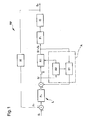
- the repeater device RP comprises an amplification line, denoted in its entirety in figure 1 by reference L, which is destined to amplify an input signal S I received into an output signal So to be transmitted.
- input signals S I and output signals So of a digital type in particular digital signals of the type defined in transmission standard DVB-T (Digital Video Broadcasting - Terrestrial) or the like. It is further stressed that the repeater device RP and the relative method for diffusing can be used for different types of signals.
- the repeater device RP has a receiving antenna and a transmitting antenna, which are types commonly used for diffusion of electromagnetic signals which respectively receive the input signal S I and transmit the output signal S O ,
- the repeater device RP advantageously comprises a echo-cancelling unit A, associated to the amplification unit L and destined to cancel or reduce an echo signal R E received by the receiving antenna and superposed on the input signal S I .
- echo signal R E is meant a disturbance due to an undesired coupling between the receiving antenna and the transmitting antenna of the repeater device RP.
- the echo signal R E is generated by the output signal So and is due to the coupling channel between the receiving antenna and the transmitting antenna, which leads to a positive retroaction on the amplification line L, with a consequent instability of the repeater device RP.
- the positive retroaction on the amplification line L has been schematically represented in figure 1 , in which reference H denotes the generic transfer function of the coupling channel.
- the amplification line L comprises an amplification unit G with predefined gain, arranged downstream with respect to the echo-cancelling unit A.
- the amplification line L comprises a reception filter F R , arranged upstream with respect to the echo-cancelling unit A and destined to filter the input signal S I .
- the reception filter F R is used for reducing the thermal noise in input and interference from adjacent channels.
- the amplification line L further comprises a transmission filter F T , arranged downstream with respect to the echo-cancelling unit A and destined to filter the output signal So, before transmission.
- the transmission filter F T is arranged along the amplification line L upstream of the amplification unit G and is used for shaping the power spectrum of the total transmitted signal, with the aim of satisfying the legally-imposed electromagnetic compatibility templates.
- the echo-cancelling unit A comprises a filter group B1 and an estimation group B2 destined to perform an estimation of the coupling channel H.
- the filter group B1 introduces a negative retroaction on the amplification line L and is constituted by a plurality of echo-cancelling filters F C , destined to cancel several cancellation time windows T C , such as to compensate for the presence of multiple groups of echo signals R E , spread out over time.
- the thus-filtered signal has been denoted generically in figures 1 and 2 with reference S I '.
- Each of the echo-cancelling filters F C can be a FIR (Finite Impulse Response) or the like. Echo-cancelling filters F C of a different type can however be used.
- the estimation group B2 advantageously comprises impulse generating means C, associated to the amplification line L and destined to generate a sequence of impulse signals S P to be transmitted via the repeater device RP.
- the estimation group B2 has estimation means D of the coupling channel H between the transmitting antenna and the receiving antenna, destined to estimate, in particular, the width and the position in time of a series of echo signals R E received and generated by the sequence of impulse signals S P transmitted.
- storing means are provided, generically denoted in figure 2 with the reference M, destined to store the control logic of the estimation means D.
- the estimation group B2 further comprises updating means E of the coefficients of each of the echo-cancelling filters F C and the position of the cancellation time windows T C , in which the updating of the coefficients is done starting from the estimated coupling channel H and, then, from the corresponding estimated echo signal R E .
- the updating means E can comprise an arithmetic and logic unit set up to dynamically modify the coefficients of the echo-cancelling filters F C .
- figure 3 illustrates an example of an impulse response h(t) of the coupling channel H, which illustrates the reception of a plurality of echo signals R E which are spaced over time and the arrangement of several cancellation time windows T C , positioned internally of a special search time window T R and at the echo signals R E .
- the filter group B1 in particular, has the input associated to the amplification line L, downstream with respect to the impulse generating means C, and has the output thereof associated to the amplification line L upstream with respect to the estimation means D.
- the impulse generating means C can usefully comprise regulation means for regulating at least one from between the power and the frequency of the impulse signals S P , such as to enable an optimal balancing between the precision in cancelling the echo signal S P and the quality of the output signal So transmitted.
- the repeater device RP advantageously comprises an on/off switch S of the amplification line L which is arranged downstream with respect to the estimation means D and upstream with respect to the impulse generating means C.
- the switch S is destined to enable selection between two operating stages of the repeater device RP.
- the switch S is open and the output signal So is constituted by the sequence of impulse signals S P .
- the switch S is closed and the output signal So comprises the series of impulse signals S P superposed on a useful signal to be retransmitted, constituted by the input signal S I received by the receiving antenna, subsequently filtered by the filter group B1 and amplified by the amplification unit G.
- the repeater device RP usefully comprises a first delay line R1 on the amplification line L and a second delay line R2 internally of the filter group B1.
- the first delay line R1 can be used for de-correlating the output signal So from the input signal S I and for providing an operating window for opportunely positioning the impulse signals Sp.
- the second delay line R2 introduces the time delay necessary for positioning the first of the cancellation windows T C at the first of the echo signals S E detected and for positioning the following cancellation windows T C .
- the signal thus time-delayed has been generically denoted in figures 1 and 2 with reference S I ".
- the method for cancelling and/or reducing the echo signals, applied to the repeater device RP includes generation, by means of the impulse generating means C, of a sequence of impulse signals S P of an appropriate power and opportunely time-spaced.
- the method comprises the transmission of such sequence of impulse signals S P , by means of the transmitting antenna of the repeater device RP, and the reception by means of the receiving antenna of an input signal S I , on which is superposed an echo signal R E at least partly generated by the sequence of impulse signals S P transmitted.
- the method comprises a stage of estimating the coupling channel H and thus the echo signal R E .
- This estimation is performed starting from the input signal S I and the impulse signal S P transmitted by the use, e.g., of statistical methods such as MLE (Maximum Likelihood Estimation) or the like.
- the method comprises updating the coefficients of the echo-cancelling filters F C of the filter group B1 on the basis of the estimated echo signal R E .
- the use of the repeater device RP firstly includes the selection of the start-up stage via the switch S.
- the switch S is open, the echo-cancelling unit A operates in open link and the output signal So transmitted by the repeater device RP is constituted exclusively by the sequence of impulse signals S P generated by the impulse generating means C.
- the signal transmitted by the repeater device RP is not a useful signal for the final user, and, consequently, the power or the frequency of the sequence of impulse signals S O transmitted can be high, in order to improve the rapidity and the quality of the initial estimation of the coupling channel H.
- the estimation group B2 of the coupling channel H determines the number and the position of a plurality of cancellation time windows T C internally of a search time window T R .
- Each of the cancellation time windows T C indicates a time interval in which the cancellation or, in any case, the reduction of the echo signal R E is performed. Then the estimation of the coupling channel H is carried out and the updating of the coefficients of the echo-cancelling filters F C operating internally of respective cancellation time windows T C , with the aim of compensating for the presence of groups of echo signals R E spaced between them over time.
- the method then comprises the selection by means of the switch S of the full functioning of the repeater device RP, a stage in which the input signal S I received is repeated.
- the echo-cancelling unit A operates in a closed link and the output signal So transmitted by the repeater device RP comprises the sequences of impulse signals S P superposed on a useful signal to be retransmitted.
- the useful signal to be retransmitted denoted in the figures with reference S I ", is constituted by the input signal S I received from the receiving antenna of the repeater device RP, filtered by the filter group B1 and thereafter amplified by the amplification unit G.
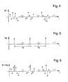
- figures 4, 5 and 6 respectively illustrate a possible useful signal to be retransmitted S I ", a possible sequence of impulse signals S P , generated at constant time intervals T P and superposable on the useful signal S I ", and the resulting output signal, denoted by S I "+S P , then amplified and transmitted by means of the repeater device RP.
- the stage of estimating the coupling channel H performed by the estimation group B2 comprises detecting variations in the estimated echo signal R E during the start-up stage, performed in the cancellation time windows T C , and the consequent updating of the coefficients of the echo-cancelling filters F C .
- the estimation during full functioning comprises, furthermore, verification and possible optimal repositioning of the cancellation time windows T C , as well as the detection of any instability phenomena.
- the method further comprises introduction of a time delay on the input signal S I by means of the delay lines R1 and R2, with the aim of positioning the cancellation windows T C at the echo signals R E detected.
- the method can comprise, during the stage of full functioning of the repeater device RP, opportunely superposing the impulse signal S P on the filtered useful signal S I ".
- This in practice means exploiting the knowledge of the input signal S I to be retransmitted, consequently selecting the position and the direction, in phase and square, of each impulse signal S P according to the position of maximum width of the input signal S I .
- figures 7, 8 and 9 illustrate, respectively, a possible useful signal to be retransmitted S I ", a possible sequence of impulse signals S P , the position in time and direction of which is opportunely selectable, and the resulting output signal, denoted by S I "+S P , then amplified and transmitted by means of the repeater device RP.
- the stage of estimating can comprise, during the stage of full functioning of the repeater device RP, the filtering of the input signal S I by implementation of adaptive algorithms such as LMS (Least Mean Squares) or others.
- the adaptive filtering can be performed parallel to the transmission of the sequence of impulse signals S P . In this way it is possible to use multiple channel estimation techniques together, with a consequently greater precision in the estimation of the coupling channel H.
- the impulse transmission e.g., enables constant monitoring of a wide time window, and rapid detection of the presence of echo signals, as well as quick control of the onset of any instability in the repeater device RP.
- more classic adaptive filtering techniques such as LMS or others, can be exploited for their well-known monitoring capacities of variations of the coupling channel H.
- the transmission of the sequence of impulse signals S P can advantageously be exploited in the start-up stage, in order to estimate the non-linear characteristics of the amplifier G and for automatically determining the pre-correction tables to be applied internally of the repeater device RP.
Landscapes
- Engineering & Computer Science (AREA)
- Computer Networks & Wireless Communication (AREA)
- Signal Processing (AREA)
- Cable Transmission Systems, Equalization Of Radio And Reduction Of Echo (AREA)
- Radio Relay Systems (AREA)
- Gyroscopes (AREA)
- Lubrication Of Internal Combustion Engines (AREA)
- Control Of Eletrric Generators (AREA)
Description
- The present invention relates to an improved repeater device for cancelling and/or reducing echo signals and to the relative method.
- In the field of telecommunications, with reference to the transmission of analog or digital signals, for some time now electronic devices known as repeaters have been used, which receive an input signal and re-transmit it in amplified form in order to guarantee that it will travel long distances.
- It is also known that when designing a repeater it is of fundamental importance that correct disturbance reduction or cancellation techniques are used, in relation to known disturbances such as echo signals, in particular due to undesired coupling between the receiving antenna and the transmitting antenna of the repeater.
- These echo signals are particularly critical when considering repeater devices known as isofrequential, as they lead to a positive retroaction on the repeater, with a consequent reduction in quality of the transmitted signal and possible instability of the system.
- This consequently considerably limits the maximum gain of the signal amplifier internally of the repeater, drastically reducing the area covered by the repeater.
- The techniques of reduction or cancellation of the echo signal used at present envisage the use, internally of the repeater, of a special filter for cancelling the echo which constitutes a negative retroaction which can completely or partially annul the effect of the above-mentioned coupling.
- This cancellation filter can be a FIR (Finite Impulse Response) or an IIR (Infinite Impulse Response) and, in general, implements suitable adaptive algorithms (LMS, BLMS, VSLMS, RLS or others), which enable to converge at an estimation of the coupling channel of the initial start-up phase of the repeater and to perform the control on the coupling channel during full functioning of the repeater, such as to compensate for any variations over time.
- In particular, the main cancellation techniques used at present are realised by means of echo-estimation methods and relative compensation which work completely in a closed link, and exploit precise characteristics of the signal to be retransmitted such as e.g. the presence of pilot under-carriers in a case of multi-carrier transmissions, such as the DVB-T (Digital Video Broadcasting - Terrestrial) signal.
- These technical details relating to cancellation, however, exhibit various drawbacks.
- Firstly, the complexity of the techniques required for extracting the data relating to the echoes from the signal received is often considerable.
- Secondly, a repeater using the above-mentioned techniques is strongly constrained to the particular signal to be retransmitted.
- Finally, in the presence of very strong echoes, these systems are easily subject to instability during the stage of start-up and initial functioning.
- Also known are cancellation techniques which during the start-up functioning phase of the repeater perform a first estimation of the coupling channel without retro-action, i.e. in open link.
- These cancellation techniques envisage the sending, on the part of the repeater, of a low-power reference signal, constituted by a sequence having good self correlation properties and suitable for enabling an estimation of the coupling channel.
- During full functioning of the repeater this reference signal is transmitted superposed on the useful signal to be retransmitted, while respecting the spectral templates of the service.
- This enables a cancellation of the echo signals to be performed, unconstrained by the specific signal characteristics to be retransmitted and, further, the system is less subject to instability phenomena during the start-up phase of repeater functioning.
- These known cancellation techniques, however, exhibit some drawbacks.
- In particular, the use of these cancellation techniques requires, in general, considerably complex methodologies which can lead to a not inconsiderable increase in the time required for estimating the coupling channel.
- For optimal use of these techniques, therefore, a compromise has to be reached between operating speed and complexity of implementation.
- Further, the use of sequences having a good self-correlation probability is generally not easy to set up.
- For example, PN-type sequences are simple to set up but do not give excellent results, while CAZAC sequences have better properties but generating them in real-time requires special reserved archives.
- Document
US 2007/191071 A1 discloses a method for isofrequency retransmission of a digital signal. - Document
EP 1 545 022 A discloses a loop interference canceller that carries out an adaptive operation of responding to time variations of the phase or level of loop interference or key station wave. - However, the above solutions could be improved in order to obtain a considerably less complex device easily and efficiently usable for the cancellation and/or the reduction of echo signals, independently of the type of useful signal to be transmitted.
- The main aim of the present invention is to provide an improved repeater device for cancelling and/or reducing echo signals and the relative method which enable cancellation and/or reduction of echo signals with a stable system, independently of the type of useful signal to be transmitted and with the use of considerably less complex devices with respect to solutions at present available. A further object of the present invention is to provide an improved repeater device for cancelling and/or reducing echo signals and the relative method which enable the above-mentioned drawbacks in the prior art to be obviated with a rational, simple, easily applicable and relatively inexpensive solution. The above-mentioned objects are attained with the present improved repeater device for cancelling and/or reducing echo signals, comprising at least an amplification line of an input signal received into an output signal to be transmitted and at least an echo-cancelling unit associated to said amplification line for reducing or cancelling an echo signal received, generated by said output signal and superposed on said input signal, said echo-cancelling unit having at least an echo-cancelling filter, characterised in that said echo-cancelling unit comprises impulse generating means associated to said amplification line and suitable for generating at least an impulse signal to be transmitted, estimation means for estimating said echo signal starting from said input signal and from said impulse signal transmitted, and means for updating the coefficients of the echo-cancelling filter starting from the estimated echo signal.
- The above objects are also attained by the present method for cancelling and/or reducing echo signals in repeater devices, characterised in that it comprises: at least a stage of generating at least an impulse signal; at least a stage of transmitting an output signal comprising said impulse signal; at least a stage of receiving an input signal on which an echo signal is superposed, which echo signal is at least in part generated by said impulse signal transmitted; at least a stage of estimating said echo signal performed starting from said input signal and from said impulse signal transmitted; at least a stage of updating coefficients of at least a cancelling filter of said echo signal performed starting from the estimated echo signal.
- Further characteristics and advantages of the present invention will better emerge from the following description of a preferred though non exclusive embodiment of an improved repeater device for cancelling and/or reducing echo signals and the relative method, illustrated by way of non-limiting example in the accompanying figures of the drawings, in which:
-
figure 1 is a general structural diagram of the repeater device according to the invention; -
figure 2 is a general structural diagram of the echo-cancelling unit of the repeater device according to the invention; -
figure 3 is an example of an echo signal received by the repeater device according to the invention in response to an impulse signal transmitted; -
figures 4, 5 and 6 illustrate an example of signals processed and transmitted by means of a first embodiment of the repeater device according to the invention;figures 7, 8, 9 and 10 illustrate an example of signals processed and transmitted by means of a second embodiment of the repeater device according to the invention. - With special reference to the figures of the drawings, RP denotes in its entirety a repeater device, of a type usable for operating with analog or digital signals, improved for cancelling or in any case reducing echo signals.
- The repeater device RP comprises an amplification line, denoted in its entirety in
figure 1 by reference L, which is destined to amplify an input signal SI received into an output signal So to be transmitted. - In the present description reference will be made to input signals SI and output signals So of a digital type, in particular digital signals of the type defined in transmission standard DVB-T (Digital Video Broadcasting - Terrestrial) or the like. It is further stressed that the repeater device RP and the relative method for diffusing can be used for different types of signals.
- The repeater device RP has a receiving antenna and a transmitting antenna, which are types commonly used for diffusion of electromagnetic signals which respectively receive the input signal SI and transmit the output signal SO,
- The repeater device RP advantageously comprises a echo-cancelling unit A, associated to the amplification unit L and destined to cancel or reduce an echo signal RE received by the receiving antenna and superposed on the input signal SI.
- In the present description, by the term echo signal RE is meant a disturbance due to an undesired coupling between the receiving antenna and the transmitting antenna of the repeater device RP.
- The echo signal RE, then, is generated by the output signal So and is due to the coupling channel between the receiving antenna and the transmitting antenna, which leads to a positive retroaction on the amplification line L, with a consequent instability of the repeater device RP. The positive retroaction on the amplification line L has been schematically represented in
figure 1 , in which reference H denotes the generic transfer function of the coupling channel. - The amplification line L comprises an amplification unit G with predefined gain, arranged downstream with respect to the echo-cancelling unit A.
- The amplification line L comprises a reception filter FR, arranged upstream with respect to the echo-cancelling unit A and destined to filter the input signal SI. In particular, the reception filter FR is used for reducing the thermal noise in input and interference from adjacent channels.
- The amplification line L further comprises a transmission filter FT, arranged downstream with respect to the echo-cancelling unit A and destined to filter the output signal So, before transmission.
- In particular, the transmission filter FT is arranged along the amplification line L upstream of the amplification unit G and is used for shaping the power spectrum of the total transmitted signal, with the aim of satisfying the legally-imposed electromagnetic compatibility templates.
- As is schematically illustrated in
figure 1 , the echo-cancelling unit A comprises a filter group B1 and an estimation group B2 destined to perform an estimation of the coupling channel H. - The filter group B1, in particular, introduces a negative retroaction on the amplification line L and is constituted by a plurality of echo-cancelling filters FC, destined to cancel several cancellation time windows TC, such as to compensate for the presence of multiple groups of echo signals RE, spread out over time. The thus-filtered signal has been denoted generically in
figures 1 and2 with reference SI'. - Each of the echo-cancelling filters FC can be a FIR (Finite Impulse Response) or the like. Echo-cancelling filters FC of a different type can however be used.
- The estimation group B2 advantageously comprises impulse generating means C, associated to the amplification line L and destined to generate a sequence of impulse signals SP to be transmitted via the repeater device RP.
- The estimation group B2 has estimation means D of the coupling channel H between the transmitting antenna and the receiving antenna, destined to estimate, in particular, the width and the position in time of a series of echo signals RE received and generated by the sequence of impulse signals SP transmitted. To this end storing means are provided, generically denoted in
figure 2 with the reference M, destined to store the control logic of the estimation means D. - The estimation group B2 further comprises updating means E of the coefficients of each of the echo-cancelling filters FC and the position of the cancellation time windows TC, in which the updating of the coefficients is done starting from the estimated coupling channel H and, then, from the corresponding estimated echo signal RE. In particular, the updating means E can comprise an arithmetic and logic unit set up to dynamically modify the coefficients of the echo-cancelling filters FC.
- By way of example,
figure 3 illustrates an example of an impulse response h(t) of the coupling channel H, which illustrates the reception of a plurality of echo signals RE which are spaced over time and the arrangement of several cancellation time windows TC, positioned internally of a special search time window TR and at the echo signals RE. - The filter group B1, in particular, has the input associated to the amplification line L, downstream with respect to the impulse generating means C, and has the output thereof associated to the amplification line L upstream with respect to the estimation means D.
- The impulse generating means C can usefully comprise regulation means for regulating at least one from between the power and the frequency of the impulse signals SP, such as to enable an optimal balancing between the precision in cancelling the echo signal SP and the quality of the output signal So transmitted. The repeater device RP advantageously comprises an on/off switch S of the amplification line L which is arranged downstream with respect to the estimation means D and upstream with respect to the impulse generating means C.
- The switch S is destined to enable selection between two operating stages of the repeater device RP.
- In a first start-up stage of the repeater device RP, the switch S is open and the output signal So is constituted by the sequence of impulse signals SP.
- In a second full functioning stage of the repeater device RP, the switch S is closed and the output signal So comprises the series of impulse signals SP superposed on a useful signal to be retransmitted, constituted by the input signal SI received by the receiving antenna, subsequently filtered by the filter group B1 and amplified by the amplification unit G.
- The repeater device RP usefully comprises a first delay line R1 on the amplification line L and a second delay line R2 internally of the filter group B1. In particular, the first delay line R1 can be used for de-correlating the output signal So from the input signal SI and for providing an operating window for opportunely positioning the impulse signals Sp.
- On the contrary, the second delay line R2 introduces the time delay necessary for positioning the first of the cancellation windows TC at the first of the echo signals SE detected and for positioning the following cancellation windows TC. The signal thus time-delayed has been generically denoted in
figures 1 and2 with reference SI". - The method for cancelling and/or reducing the echo signals, applied to the repeater device RP, includes generation, by means of the impulse generating means C, of a sequence of impulse signals SP of an appropriate power and opportunely time-spaced.
- The method comprises the transmission of such sequence of impulse signals SP, by means of the transmitting antenna of the repeater device RP, and the reception by means of the receiving antenna of an input signal SI, on which is superposed an echo signal RE at least partly generated by the sequence of impulse signals SP transmitted.
- The method comprises a stage of estimating the coupling channel H and thus the echo signal RE. This estimation is performed starting from the input signal SI and the impulse signal SP transmitted by the use, e.g., of statistical methods such as MLE (Maximum Likelihood Estimation) or the like.
- Finally, the method comprises updating the coefficients of the echo-cancelling filters FC of the filter group B1 on the basis of the estimated echo signal RE.
- In particular, the use of the repeater device RP firstly includes the selection of the start-up stage via the switch S.
- In this start-up stage the switch S is open, the echo-cancelling unit A operates in open link and the output signal So transmitted by the repeater device RP is constituted exclusively by the sequence of impulse signals SP generated by the impulse generating means C. During the start-up stage, therefore, the signal transmitted by the repeater device RP is not a useful signal for the final user, and, consequently, the power or the frequency of the sequence of impulse signals SO transmitted can be high, in order to improve the rapidity and the quality of the initial estimation of the coupling channel H.
- During the start-up stage of the repeater device RP, the estimation group B2 of the coupling channel H determines the number and the position of a plurality of cancellation time windows TC internally of a search time window TR. Each of the cancellation time windows TC indicates a time interval in which the cancellation or, in any case, the reduction of the echo signal RE is performed. Then the estimation of the coupling channel H is carried out and the updating of the coefficients of the echo-cancelling filters FC operating internally of respective cancellation time windows TC, with the aim of compensating for the presence of groups of echo signals RE spaced between them over time.
- The method then comprises the selection by means of the switch S of the full functioning of the repeater device RP, a stage in which the input signal SI received is repeated.
- During the stage of full functioning the switch S is closed, the echo-cancelling unit A operates in a closed link and the output signal So transmitted by the repeater device RP comprises the sequences of impulse signals SP superposed on a useful signal to be retransmitted. In particular, the useful signal to be retransmitted, denoted in the figures with reference SI", is constituted by the input signal SI received from the receiving antenna of the repeater device RP, filtered by the filter group B1 and thereafter amplified by the amplification unit G.
- Purely by way of example,
figures 4, 5 and 6 respectively illustrate a possible useful signal to be retransmitted SI", a possible sequence of impulse signals SP, generated at constant time intervals TP and superposable on the useful signal SI", and the resulting output signal, denoted by SI"+SP, then amplified and transmitted by means of the repeater device RP. - During full functioning, the stage of estimating the coupling channel H performed by the estimation group B2 comprises detecting variations in the estimated echo signal RE during the start-up stage, performed in the cancellation time windows TC, and the consequent updating of the coefficients of the echo-cancelling filters FC.
- The estimation during full functioning comprises, furthermore, verification and possible optimal repositioning of the cancellation time windows TC, as well as the detection of any instability phenomena.
- During full functioning of the repeater device RP, it is usefully possible to regulate the power and/or the frequency of the sequence of impulse signals SP, with the aim of enabling an optimal balancing between the precision of the cancellation of the echo signal RE and the quality of the output signal So transmitted.
- The method further comprises introduction of a time delay on the input signal SI by means of the delay lines R1 and R2, with the aim of positioning the cancellation windows TC at the echo signals RE detected.
- Advantageously the embodiment of different variants of the method of the invention is not excluded.
- In particular, in a first variant the method can comprise, during the stage of full functioning of the repeater device RP, opportunely superposing the impulse signal SP on the filtered useful signal SI". This in practice means exploiting the knowledge of the input signal SI to be retransmitted, consequently selecting the position and the direction, in phase and square, of each impulse signal SP according to the position of maximum width of the input signal SI.
- Purely by way of example,
figures 7, 8 and 9 illustrate, respectively, a possible useful signal to be retransmitted SI", a possible sequence of impulse signals SP, the position in time and direction of which is opportunely selectable, and the resulting output signal, denoted by SI"+SP, then amplified and transmitted by means of the repeater device RP. - In this way the power of the impulse signal transmitted is significantly reduced, illustrated in
figure 10 with reference SP', in identical conditions of size of impulses transmitted overall, with a consequent reduction in the disturbances perceived by the final user and a general improvement in performance. - In a second variant of the method of the invention, the stage of estimating can comprise, during the stage of full functioning of the repeater device RP, the filtering of the input signal SI by implementation of adaptive algorithms such as LMS (Least Mean Squares) or others. The adaptive filtering can be performed parallel to the transmission of the sequence of impulse signals SP. In this way it is possible to use multiple channel estimation techniques together, with a consequently greater precision in the estimation of the coupling channel H.
- The impulse transmission, e.g., enables constant monitoring of a wide time window, and rapid detection of the presence of echo signals, as well as quick control of the onset of any instability in the repeater device RP. At the same time, more classic adaptive filtering techniques, such as LMS or others, can be exploited for their well-known monitoring capacities of variations of the coupling channel H.
- The transmission of the sequence of impulse signals SP can advantageously be exploited in the start-up stage, in order to estimate the non-linear characteristics of the amplifier G and for automatically determining the pre-correction tables to be applied internally of the repeater device RP.
- Similarly, during full functioning, periodic estimations can be made of the non-linear characteristics of the amplifier G in order to adapt the pre-corrector to any eventual variations.
- It has in fact been ascertained how the described invention achieves the proposed objects and in particular the fact is underlined that the described repeater device and method enable cancellation and/or reduction of echo signals using a stable system independently of the type of useful signal to be transmitted and with the use of considerably less complex devices than in the prior art.
- The invention thus conceived is susceptible to numerous modifications and variations, all of which falling within the scope of the inventive concept. Furthermore all the details can be replaced with others that are technically equivalent.
- In practice, the materials used, as well as the contingent shapes and dimensions, may be any according to requirements without because of this moving outside the protection scope of the following claims.
Claims (17)
- An improved repeater device (RP) for cancelling and/or reducing echo signals, comprising at least an amplification line (L) of an input signal (SI) received by a receiving antenna into an output signal (SO) to be transmitted by a transmitting antenna and at least an echo-cancelling unit (A) associated to said amplification line (L) for reducing or cancelling an echo signal (RE) received by said receiving antenna, generated by said output signal (SO) and superposed on said input signal (SI), due to the coupling channel (H) between said receiving antenna and said transmitting antenna, said echo-cancelling unit (A) having at least an echo-cancelling filter (FC), characterised in that said echo-cancelling unit (A) comprises impulse generating means (C) associated to said amplification line (L) and suitable for generating at least an impulse signal (SP) to be transmitted by said transmitting antenna, estimation means (D) of said coupling channel (H) between the transmitting antenna and the receiving antenna for estimating from said input signal (SI) and from said impulse signal (SP) the width and the position in time of at least an echo signal (RE) received by said receiving antenna and generated by said impulse signal (SP) transmitted, and updating means (E) for updating the coefficients of the echo-cancelling filter (FC) starting from the estimated echo signal (RE).
- Repeater device (RP) according to claim 1, characterised in that it comprises at least an on/off switch (S) of said amplification line (L) arranged downstream with respect to the estimation means (D) and upstream with respect to said impulse generating means (C) and destined to enable a selection between two operating stages of the repeater device (RP): a first start-up stage wherein the switch (S) is open and the output signal (SO) is constituted by said impulse signal (SP) and a second full functioning stage wherein the switch (S) is closed and the output signal (SO) comprises said impulse signal (SP) superposed on a useful signal (SI") to be retransmitted.
- Repeater device (RP) according to claim 1, characterised in that said echo-cancelling filter (FC) is of the type of a negative retroaction filter.
- Repeater device (RP) according to claim 1, characterised in that said echo-cancelling filter (FC) has the input associated to said amplification line (L), downstream with respect to said impulse generating means (C).
- Repeater device (RP) according to claim 1, characterised in that said echo-cancelling filter (FC) has the output associated to said amplification line (L), upstream with respect to said estimation means (D).
- Repeater device (RP) according to claim 1, characterised in that said amplification line (L) comprises at least a delay line (R1).
- Repeater device (RP) according to claim 1, characterised in that said impulse generating means (C) comprise regulation means for regulating at least one from between the power and the frequency of said impulse signal (SP).
- Repeater device (RP) according to claim 1, characterised in that said amplification line (L) comprises at least an amplification unit (G) of said input signal (SI).
- A method for cancelling and/or reducing echo signals in a repeater device (RP), wherein said repeater device (RP) comprises at least an amplification line (L) of an input signal (SI) received by a receiving antenna into an output signal (SO) to be transmitted by a transmitting antenna and at least an echo-cancelling unit (A) associated to said amplification line (L) for reducing or cancelling an echo signal (RE) received by said receiving antenna, generated by said output signal (SO) and superposed on said input signal (SI), due to the coupling channel (H) between said receiving antenna and said transmitting antenna, said echo-cancelling unit (A) having at least an echo-cancelling filter (FC), characterised in that the method comprises:- at least a stage of generating at least an impulse signal (SP) to be transmitted by said transmitting antenna;- at least a stage of transmitting by said transmitting antenna said output signal (SO) comprising said impulse signal (SP);- at least a stage of receiving by said receiving antenna an input signal (SI) on which an echo signal (RE) is superposed, which echo signal (RE) is at least partly generated by said impulse signal (SP) transmitted;- at least a stage of estimating the width and the position in time of said echo signal (RE) generated by said impulse signal (SP) transmitted, performed starting from said input signal (SI) and by said impulse signal (SP);- at least a stage of updating the coefficients of said echo-cancelling filter (FC) for cancelling said echo signal (RE), performed starting from the estimated echo signal (RE).
- Method according to claim 9, characterised in that it comprises the selection between a start-up stage, in which said output signal (SO) is constituted by said impulse signal (SP), and a full functioning stage, in which said output signal (SO) comprises said impulse signal (SP) and at least a useful signal (SI") received and to be retransmitted.
- Method according to claim 9, characterised in that it comprises determining at least a cancellation time window (TC) of said echo signal (RE).
- Method according to claim 11, characterised in that said cancellation time window (TC) is determined internally of a predetermined search time window (TR).
- Method according to claim 11, characterised in that said stage of estimating comprises detecting variations of said echo signal (RE) internally of said cancellation time window (TC).
- Method according to claim 11, characterised in that said stage of estimating comprises verifying and repositioning of said cancellation time window (TC).
- Method according to claim 9, characterised in that it comprises a stage of regulating at least one from between the power and the frequency of said impulse signal (SP).
- Method according to claim 9, characterised in that said stage of generating comprises periodic generation of impulse signals (SP) of an appropriate power which impulse signals (SP) are appropriately time-spaced from one another.
- Method according to claim 11, characterised in that it comprises at least a stage of introducing a time delay of said input signal (SI) destined to position said cancellation time window (TC) at said echo signal (RE) detected.
Applications Claiming Priority (2)
| Application Number | Priority Date | Filing Date | Title |
|---|---|---|---|
| ITMO20080161 ITMO20080161A1 (en) | 2008-05-27 | 2008-05-27 | REPEATED DEVICE FOR THE CANCELLATION AND / OR REDUCTION OF ECO SIGNALS AND ITS METHOD |
| PCT/IB2009/005664 WO2009144556A1 (en) | 2008-05-27 | 2009-05-21 | Echo cancellation for dvb repeaters |
Publications (2)
| Publication Number | Publication Date |
|---|---|
| EP2281350A1 EP2281350A1 (en) | 2011-02-09 |
| EP2281350B1 true EP2281350B1 (en) | 2014-01-15 |
Family
ID=40302885
Family Applications (1)
| Application Number | Title | Priority Date | Filing Date |
|---|---|---|---|
| EP09754184.1A Not-in-force EP2281350B1 (en) | 2008-05-27 | 2009-05-21 | Echo cancellation for dvb repeaters |
Country Status (3)
| Country | Link |
|---|---|
| EP (1) | EP2281350B1 (en) |
| IT (1) | ITMO20080161A1 (en) |
| WO (1) | WO2009144556A1 (en) |
Family Cites Families (2)
| Publication number | Priority date | Publication date | Assignee | Title |
|---|---|---|---|---|
| JP4464651B2 (en) | 2002-10-11 | 2010-05-19 | パナソニック株式会社 | Rounding canceller, relay system, and rounding cancellation method |
| FR2888702B1 (en) | 2005-07-13 | 2007-08-31 | Teamcast Sa | METHOD OF ISOFREQUENCY RE-TRANSMITTING AN ECHO REMOVAL DIGITAL SIGNAL AND CORRESPONDING RE-TRANSMITTING DEVICE |
-
2008
- 2008-05-27 IT ITMO20080161 patent/ITMO20080161A1/en unknown
-
2009
- 2009-05-21 WO PCT/IB2009/005664 patent/WO2009144556A1/en not_active Ceased
- 2009-05-21 EP EP09754184.1A patent/EP2281350B1/en not_active Not-in-force
Also Published As
| Publication number | Publication date |
|---|---|
| ITMO20080161A1 (en) | 2009-11-28 |
| EP2281350A1 (en) | 2011-02-09 |
| WO2009144556A1 (en) | 2009-12-03 |
Similar Documents
| Publication | Publication Date | Title |
|---|---|---|
| US8296347B2 (en) | Use of line characterization to configure physical layered devices | |
| US8428192B2 (en) | Adaptive interference canceling system and method | |
| US6285859B1 (en) | Method for predistortion of a signal transmitted between two units of a telecommunications network and a unit for carrying out the method | |
| EP2173040B1 (en) | Single-port signal repeater | |
| CN101420246B (en) | Method, apparatus and transceiver for counteracting transmission interference by the transceiver | |
| US5181198A (en) | Coordinated transmission for two-pair digital subscriber lines | |
| US7346012B2 (en) | Transceiver with accelerated echo canceller convergence | |
| US20080232268A1 (en) | LMS Adaptive Filter for Digital Cancellation of Second Order Inter-Modulation Due to Transmitter Leakage | |
| EP2345177B1 (en) | Method and arrangement in a communication system | |
| US20190181897A1 (en) | Method for estimating self-interference signal based on iterative estimation and apparatus using the same | |
| CN101488800B (en) | Apparatus and method for removing a echo signal in a communication system | |
| CN102124665A (en) | Wireless communication device and control method | |
| CN101350798B (en) | Apparatus and method for eliminating echo, transmit-receive equipment containing the apparatus | |
| EP2281350A1 (en) | Echo cancellation for dvb repeaters | |
| US20110170633A1 (en) | Transmission method taking echo into account | |
| US10181892B2 (en) | Interference cancellation repeater | |
| KR100976726B1 (en) | Co-channel repeater and method | |
| KR102417564B1 (en) | Apparatus and method for wireless relaying | |
| CN101296068A (en) | Digital synchronization receiving device and signal processing method thereof | |
| KR100969168B1 (en) | Feedback Interference Removal Method | |
| KR102563334B1 (en) | Apparatus and method for wireless relaying | |
| KR102563345B1 (en) | Apparatus and method for wireless relaying | |
| KR102563333B1 (en) | Apparatus and method for wireless relaying | |
| KR101508965B1 (en) | Interference cancellation system and repeater using thereof | |
| US20080095225A1 (en) | System, Multi-Stage Equalizer and Equalization Method |
Legal Events
| Date | Code | Title | Description |
|---|---|---|---|
| PUAI | Public reference made under article 153(3) epc to a published international application that has entered the european phase |
Free format text: ORIGINAL CODE: 0009012 |
|
| 17P | Request for examination filed |
Effective date: 20101124 |
|
| AK | Designated contracting states |
Kind code of ref document: A1 Designated state(s): AT BE BG CH CY CZ DE DK EE ES FI FR GB GR HR HU IE IS IT LI LT LU LV MC MK MT NL NO PL PT RO SE SI SK TR |
|
| AX | Request for extension of the european patent |
Extension state: AL BA RS |
|
| DAX | Request for extension of the european patent (deleted) | ||
| 17Q | First examination report despatched |
Effective date: 20130117 |
|
| GRAP | Despatch of communication of intention to grant a patent |
Free format text: ORIGINAL CODE: EPIDOSNIGR1 |
|
| INTG | Intention to grant announced |
Effective date: 20130730 |
|
| GRAS | Grant fee paid |
Free format text: ORIGINAL CODE: EPIDOSNIGR3 |
|
| GRAA | (expected) grant |
Free format text: ORIGINAL CODE: 0009210 |
|
| AK | Designated contracting states |
Kind code of ref document: B1 Designated state(s): AT BE BG CH CY CZ DE DK EE ES FI FR GB GR HR HU IE IS IT LI LT LU LV MC MK MT NL NO PL PT RO SE SI SK TR |
|
| REG | Reference to a national code |
Ref country code: CH Ref legal event code: EP Ref country code: GB Ref legal event code: FG4D |
|
| REG | Reference to a national code |
Ref country code: AT Ref legal event code: REF Ref document number: 650212 Country of ref document: AT Kind code of ref document: T Effective date: 20140215 |
|
| REG | Reference to a national code |
Ref country code: IE Ref legal event code: FG4D |
|
| REG | Reference to a national code |
Ref country code: DE Ref legal event code: R096 Ref document number: 602009021455 Country of ref document: DE Effective date: 20140227 |
|
| REG | Reference to a national code |
Ref country code: NL Ref legal event code: VDEP Effective date: 20140115 |
|
| REG | Reference to a national code |
Ref country code: AT Ref legal event code: MK05 Ref document number: 650212 Country of ref document: AT Kind code of ref document: T Effective date: 20140115 |
|
| REG | Reference to a national code |
Ref country code: LT Ref legal event code: MG4D |
|
| PG25 | Lapsed in a contracting state [announced via postgrant information from national office to epo] |
Ref country code: NO Free format text: LAPSE BECAUSE OF FAILURE TO SUBMIT A TRANSLATION OF THE DESCRIPTION OR TO PAY THE FEE WITHIN THE PRESCRIBED TIME-LIMIT Effective date: 20140415 Ref country code: IS Free format text: LAPSE BECAUSE OF FAILURE TO SUBMIT A TRANSLATION OF THE DESCRIPTION OR TO PAY THE FEE WITHIN THE PRESCRIBED TIME-LIMIT Effective date: 20140515 Ref country code: LT Free format text: LAPSE BECAUSE OF FAILURE TO SUBMIT A TRANSLATION OF THE DESCRIPTION OR TO PAY THE FEE WITHIN THE PRESCRIBED TIME-LIMIT Effective date: 20140115 |
|
| PG25 | Lapsed in a contracting state [announced via postgrant information from national office to epo] |
Ref country code: NL Free format text: LAPSE BECAUSE OF FAILURE TO SUBMIT A TRANSLATION OF THE DESCRIPTION OR TO PAY THE FEE WITHIN THE PRESCRIBED TIME-LIMIT Effective date: 20140115 Ref country code: PT Free format text: LAPSE BECAUSE OF FAILURE TO SUBMIT A TRANSLATION OF THE DESCRIPTION OR TO PAY THE FEE WITHIN THE PRESCRIBED TIME-LIMIT Effective date: 20140515 Ref country code: CY Free format text: LAPSE BECAUSE OF FAILURE TO SUBMIT A TRANSLATION OF THE DESCRIPTION OR TO PAY THE FEE WITHIN THE PRESCRIBED TIME-LIMIT Effective date: 20140115 Ref country code: SE Free format text: LAPSE BECAUSE OF FAILURE TO SUBMIT A TRANSLATION OF THE DESCRIPTION OR TO PAY THE FEE WITHIN THE PRESCRIBED TIME-LIMIT Effective date: 20140115 Ref country code: AT Free format text: LAPSE BECAUSE OF FAILURE TO SUBMIT A TRANSLATION OF THE DESCRIPTION OR TO PAY THE FEE WITHIN THE PRESCRIBED TIME-LIMIT Effective date: 20140115 Ref country code: FI Free format text: LAPSE BECAUSE OF FAILURE TO SUBMIT A TRANSLATION OF THE DESCRIPTION OR TO PAY THE FEE WITHIN THE PRESCRIBED TIME-LIMIT Effective date: 20140115 Ref country code: ES Free format text: LAPSE BECAUSE OF FAILURE TO SUBMIT A TRANSLATION OF THE DESCRIPTION OR TO PAY THE FEE WITHIN THE PRESCRIBED TIME-LIMIT Effective date: 20140115 |
|
| PG25 | Lapsed in a contracting state [announced via postgrant information from national office to epo] |
Ref country code: LV Free format text: LAPSE BECAUSE OF FAILURE TO SUBMIT A TRANSLATION OF THE DESCRIPTION OR TO PAY THE FEE WITHIN THE PRESCRIBED TIME-LIMIT Effective date: 20140115 Ref country code: BE Free format text: LAPSE BECAUSE OF FAILURE TO SUBMIT A TRANSLATION OF THE DESCRIPTION OR TO PAY THE FEE WITHIN THE PRESCRIBED TIME-LIMIT Effective date: 20140115 Ref country code: HR Free format text: LAPSE BECAUSE OF FAILURE TO SUBMIT A TRANSLATION OF THE DESCRIPTION OR TO PAY THE FEE WITHIN THE PRESCRIBED TIME-LIMIT Effective date: 20140115 |
|
| REG | Reference to a national code |
Ref country code: DE Ref legal event code: R097 Ref document number: 602009021455 Country of ref document: DE |
|
| PG25 | Lapsed in a contracting state [announced via postgrant information from national office to epo] |
Ref country code: RO Free format text: LAPSE BECAUSE OF FAILURE TO SUBMIT A TRANSLATION OF THE DESCRIPTION OR TO PAY THE FEE WITHIN THE PRESCRIBED TIME-LIMIT Effective date: 20140115 Ref country code: DK Free format text: LAPSE BECAUSE OF FAILURE TO SUBMIT A TRANSLATION OF THE DESCRIPTION OR TO PAY THE FEE WITHIN THE PRESCRIBED TIME-LIMIT Effective date: 20140115 Ref country code: CZ Free format text: LAPSE BECAUSE OF FAILURE TO SUBMIT A TRANSLATION OF THE DESCRIPTION OR TO PAY THE FEE WITHIN THE PRESCRIBED TIME-LIMIT Effective date: 20140115 Ref country code: EE Free format text: LAPSE BECAUSE OF FAILURE TO SUBMIT A TRANSLATION OF THE DESCRIPTION OR TO PAY THE FEE WITHIN THE PRESCRIBED TIME-LIMIT Effective date: 20140115 |
|
| PLBE | No opposition filed within time limit |
Free format text: ORIGINAL CODE: 0009261 |
|
| STAA | Information on the status of an ep patent application or granted ep patent |
Free format text: STATUS: NO OPPOSITION FILED WITHIN TIME LIMIT |
|
| PG25 | Lapsed in a contracting state [announced via postgrant information from national office to epo] |
Ref country code: PL Free format text: LAPSE BECAUSE OF FAILURE TO SUBMIT A TRANSLATION OF THE DESCRIPTION OR TO PAY THE FEE WITHIN THE PRESCRIBED TIME-LIMIT Effective date: 20140115 Ref country code: SK Free format text: LAPSE BECAUSE OF FAILURE TO SUBMIT A TRANSLATION OF THE DESCRIPTION OR TO PAY THE FEE WITHIN THE PRESCRIBED TIME-LIMIT Effective date: 20140115 |
|
| 26N | No opposition filed |
Effective date: 20141016 |
|
| PG25 | Lapsed in a contracting state [announced via postgrant information from national office to epo] |
Ref country code: LU Free format text: LAPSE BECAUSE OF FAILURE TO SUBMIT A TRANSLATION OF THE DESCRIPTION OR TO PAY THE FEE WITHIN THE PRESCRIBED TIME-LIMIT Effective date: 20140521 |
|
| REG | Reference to a national code |
Ref country code: CH Ref legal event code: PL |
|
| GBPC | Gb: european patent ceased through non-payment of renewal fee |
Effective date: 20140521 |
|
| PG25 | Lapsed in a contracting state [announced via postgrant information from national office to epo] |
Ref country code: MC Free format text: LAPSE BECAUSE OF FAILURE TO SUBMIT A TRANSLATION OF THE DESCRIPTION OR TO PAY THE FEE WITHIN THE PRESCRIBED TIME-LIMIT Effective date: 20140115 Ref country code: LI Free format text: LAPSE BECAUSE OF NON-PAYMENT OF DUE FEES Effective date: 20140531 Ref country code: CH Free format text: LAPSE BECAUSE OF NON-PAYMENT OF DUE FEES Effective date: 20140531 |
|
| REG | Reference to a national code |
Ref country code: DE Ref legal event code: R097 Ref document number: 602009021455 Country of ref document: DE Effective date: 20141016 |
|
| REG | Reference to a national code |
Ref country code: IE Ref legal event code: MM4A |
|
| PG25 | Lapsed in a contracting state [announced via postgrant information from national office to epo] |
Ref country code: IE Free format text: LAPSE BECAUSE OF NON-PAYMENT OF DUE FEES Effective date: 20140521 |
|
| REG | Reference to a national code |
Ref country code: FR Ref legal event code: PLFP Year of fee payment: 7 |
|
| PG25 | Lapsed in a contracting state [announced via postgrant information from national office to epo] |
Ref country code: SI Free format text: LAPSE BECAUSE OF FAILURE TO SUBMIT A TRANSLATION OF THE DESCRIPTION OR TO PAY THE FEE WITHIN THE PRESCRIBED TIME-LIMIT Effective date: 20140115 Ref country code: GB Free format text: LAPSE BECAUSE OF NON-PAYMENT OF DUE FEES Effective date: 20140521 |
|
| PG25 | Lapsed in a contracting state [announced via postgrant information from national office to epo] |
Ref country code: MT Free format text: LAPSE BECAUSE OF FAILURE TO SUBMIT A TRANSLATION OF THE DESCRIPTION OR TO PAY THE FEE WITHIN THE PRESCRIBED TIME-LIMIT Effective date: 20140115 |
|
| REG | Reference to a national code |
Ref country code: FR Ref legal event code: PLFP Year of fee payment: 8 |
|
| REG | Reference to a national code |
Ref country code: FR Ref legal event code: CA Effective date: 20160523 |
|
| PG25 | Lapsed in a contracting state [announced via postgrant information from national office to epo] |
Ref country code: GR Free format text: LAPSE BECAUSE OF FAILURE TO SUBMIT A TRANSLATION OF THE DESCRIPTION OR TO PAY THE FEE WITHIN THE PRESCRIBED TIME-LIMIT Effective date: 20140416 Ref country code: BG Free format text: LAPSE BECAUSE OF FAILURE TO SUBMIT A TRANSLATION OF THE DESCRIPTION OR TO PAY THE FEE WITHIN THE PRESCRIBED TIME-LIMIT Effective date: 20140115 |
|
| PG25 | Lapsed in a contracting state [announced via postgrant information from national office to epo] |
Ref country code: TR Free format text: LAPSE BECAUSE OF FAILURE TO SUBMIT A TRANSLATION OF THE DESCRIPTION OR TO PAY THE FEE WITHIN THE PRESCRIBED TIME-LIMIT Effective date: 20140115 Ref country code: HU Free format text: LAPSE BECAUSE OF FAILURE TO SUBMIT A TRANSLATION OF THE DESCRIPTION OR TO PAY THE FEE WITHIN THE PRESCRIBED TIME-LIMIT; INVALID AB INITIO Effective date: 20090521 |
|
| REG | Reference to a national code |
Ref country code: FR Ref legal event code: PLFP Year of fee payment: 9 |
|
| REG | Reference to a national code |
Ref country code: FR Ref legal event code: PLFP Year of fee payment: 10 |
|
| PG25 | Lapsed in a contracting state [announced via postgrant information from national office to epo] |
Ref country code: MK Free format text: LAPSE BECAUSE OF FAILURE TO SUBMIT A TRANSLATION OF THE DESCRIPTION OR TO PAY THE FEE WITHIN THE PRESCRIBED TIME-LIMIT Effective date: 20140115 |
|
| PGFP | Annual fee paid to national office [announced via postgrant information from national office to epo] |
Ref country code: FR Payment date: 20210525 Year of fee payment: 13 Ref country code: DE Payment date: 20210527 Year of fee payment: 13 |
|
| PGFP | Annual fee paid to national office [announced via postgrant information from national office to epo] |
Ref country code: IT Payment date: 20210531 Year of fee payment: 13 |
|
| REG | Reference to a national code |
Ref country code: DE Ref legal event code: R119 Ref document number: 602009021455 Country of ref document: DE |
|
| PG25 | Lapsed in a contracting state [announced via postgrant information from national office to epo] |
Ref country code: FR Free format text: LAPSE BECAUSE OF NON-PAYMENT OF DUE FEES Effective date: 20220531 |
|
| PG25 | Lapsed in a contracting state [announced via postgrant information from national office to epo] |
Ref country code: DE Free format text: LAPSE BECAUSE OF NON-PAYMENT OF DUE FEES Effective date: 20221201 |
|
| PG25 | Lapsed in a contracting state [announced via postgrant information from national office to epo] |
Ref country code: IT Free format text: LAPSE BECAUSE OF NON-PAYMENT OF DUE FEES Effective date: 20220521 |