EP2280456A1 - Electrical connector having a dielectric insert for retaining an electrical contact - Google Patents
Electrical connector having a dielectric insert for retaining an electrical contact Download PDFInfo
- Publication number
- EP2280456A1 EP2280456A1 EP10170784A EP10170784A EP2280456A1 EP 2280456 A1 EP2280456 A1 EP 2280456A1 EP 10170784 A EP10170784 A EP 10170784A EP 10170784 A EP10170784 A EP 10170784A EP 2280456 A1 EP2280456 A1 EP 2280456A1
- Authority
- EP
- European Patent Office
- Prior art keywords
- contact
- electrical
- housing
- dielectric insert
- electrical contact
- Prior art date
- Legal status (The legal status is an assumption and is not a legal conclusion. Google has not performed a legal analysis and makes no representation as to the accuracy of the status listed.)
- Withdrawn
Links
- 230000013011 mating Effects 0.000 claims abstract description 74
- 230000014759 maintenance of location Effects 0.000 description 10
- 239000002184 metal Substances 0.000 description 10
- 239000004020 conductor Substances 0.000 description 4
- 230000000295 complement effect Effects 0.000 description 3
- 230000000717 retained effect Effects 0.000 description 3
Images


Classifications
-
- H—ELECTRICITY
- H01—ELECTRIC ELEMENTS
- H01R—ELECTRICALLY-CONDUCTIVE CONNECTIONS; STRUCTURAL ASSOCIATIONS OF A PLURALITY OF MUTUALLY-INSULATED ELECTRICAL CONNECTING ELEMENTS; COUPLING DEVICES; CURRENT COLLECTORS
- H01R13/00—Details of coupling devices of the kinds covered by groups H01R12/70 or H01R24/00 - H01R33/00
- H01R13/40—Securing contact members in or to a base or case; Insulating of contact members
- H01R13/42—Securing in a demountable manner
- H01R13/424—Securing in base or case composed of a plurality of insulating parts having at least one resilient insulating part
-
- H—ELECTRICITY
- H01—ELECTRIC ELEMENTS
- H01R—ELECTRICALLY-CONDUCTIVE CONNECTIONS; STRUCTURAL ASSOCIATIONS OF A PLURALITY OF MUTUALLY-INSULATED ELECTRICAL CONNECTING ELEMENTS; COUPLING DEVICES; CURRENT COLLECTORS
- H01R13/00—Details of coupling devices of the kinds covered by groups H01R12/70 or H01R24/00 - H01R33/00
- H01R13/40—Securing contact members in or to a base or case; Insulating of contact members
- H01R13/42—Securing in a demountable manner
- H01R13/422—Securing in resilient one-piece base or case, e.g. by friction; One-piece base or case formed with resilient locking means
- H01R13/4223—Securing in resilient one-piece base or case, e.g. by friction; One-piece base or case formed with resilient locking means comprising integral flexible contact retaining fingers
- H01R13/4226—Securing in resilient one-piece base or case, e.g. by friction; One-piece base or case formed with resilient locking means comprising integral flexible contact retaining fingers comprising two or more integral flexible retaining fingers acting on a single contact
-
- H—ELECTRICITY
- H01—ELECTRIC ELEMENTS
- H01R—ELECTRICALLY-CONDUCTIVE CONNECTIONS; STRUCTURAL ASSOCIATIONS OF A PLURALITY OF MUTUALLY-INSULATED ELECTRICAL CONNECTING ELEMENTS; COUPLING DEVICES; CURRENT COLLECTORS
- H01R13/00—Details of coupling devices of the kinds covered by groups H01R12/70 or H01R24/00 - H01R33/00
- H01R13/46—Bases; Cases
- H01R13/502—Bases; Cases composed of different pieces
- H01R13/506—Bases; Cases composed of different pieces assembled by snap action of the parts
-
- H—ELECTRICITY
- H01—ELECTRIC ELEMENTS
- H01R—ELECTRICALLY-CONDUCTIVE CONNECTIONS; STRUCTURAL ASSOCIATIONS OF A PLURALITY OF MUTUALLY-INSULATED ELECTRICAL CONNECTING ELEMENTS; COUPLING DEVICES; CURRENT COLLECTORS
- H01R43/00—Apparatus or processes specially adapted for manufacturing, assembling, maintaining, or repairing of line connectors or current collectors or for joining electric conductors
- H01R43/20—Apparatus or processes specially adapted for manufacturing, assembling, maintaining, or repairing of line connectors or current collectors or for joining electric conductors for assembling or disassembling contact members with insulating base, case or sleeve
Definitions
- the subject matter herein relates generally to electrical connectors, and more particularly, to a dielectric insert for retaining an electrical contact within the housing of an electrical connector.
- Electrical connectors are used to electrically connect a wide variety of electrical components.
- electrical drawer connectors are used to connect various workstations and other electrical components to wide-area network (WAN) and local-area network (LAN) servers.
- Drawer connectors typically include a housing that holds a plurality of electrical contacts having terminating segments that terminate electrical wires and/or electrical cables that extend from the server.
- the electrical contacts include mating segments that extend along a mating interface of the housing of the drawer connector.
- the housing can be mated with the mating connector of an electrical component at the mating interface to electrically connect the electrical component to the server.
- the terminating segments of the electrical contacts of drawer connectors are sometimes held within a mounting cavity of the housing using a dielectric insert and a metal retention clip.
- the dielectric insert is first loaded into the mounting cavity of the housing.
- the metal retention clip is hand-loaded into a contact channel that extends through the dielectric insert, such that the dielectric insert extends around the metal retention clip.
- the electrical contact is then inserted into an opening within the metal retention clip such that the metal retention clip extends around the terminating segment of the electrical contact.
- the metal retention clip includes a plurality of fingers that extend radially inwardly and engage the terminating segment of the electrical contact to retain the electrical contact within the mounting cavity of the housing. Using the metal retention clip to retain the electrical contact within the mounting cavity is not without disadvantages.
- the metal retention clip may increase a complexity and/or a number of components of the drawer connector, which may increase a cost of the drawer connector. Moreover, it may be difficult and/or time-consuming to separately load each of the dielectric insert, the metal retention clip, and the electrical contact within the mating cavity of the housing. The metal retention clip may therefore increase a cost, difficulty, and/or time of assembling the drawer connector.
- an electrical connector including a housing having a mating interface and an interior chamber, an electrical contact having a terminating segment and a mating segment, and a dielectric insert held within the interior chamber of the housing.
- the dielectric insert includes a contact channel and a resilient finger extending into the contact channel.
- the terminating segment of the electrical contact extends within the contact channel of the dielectric insert.
- the resilient finger is engaged with the terminating segment of the electrical contact to retain the electrical contact within the interior chamber of the housing such that the mating segment of the electrical contact extends along the mating interface of the housing.
- an electrical connector in another embodiment, includes a housing having a mating interface and an interior chamber, an electrical contact having a terminating segment and a mating segment, and a dielectric insert held within the interior chamber of the housing.
- the dielectric insert includes a base having a contact channel extending therethrough and resilient fingers extending from the base into the contact channel.
- the terminating segment of the electrical contact extends within the contact channel of the dielectric insert.
- the resilient fingers are spaced apart around a periphery of the terminating segment of the electrical contact.
- the resilient fingers include free ends that are engaged with the terminating segment of the electrical contact to retain the electrical contact within the interior chamber of the housing such that the mating segment of the electrical contact extends along the mating interface of the housing.
- Figure 1 is a perspective view of an exemplary embodiment of an electrical connector.
- Figure 2 is a cross-sectional of an exemplary embodiment of a housing of the electrical connector shown in Figure 1 .
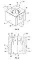
- Figure 3 is a perspective view of an exemplary embodiment of a dielectric insert of the electrical connector shown in Figure 1 .
- Figure 4 is a cross-sectional view of the dielectric insert shown in Figure 3 taken along line 4-4 of Figure 3 .
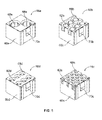
- Figure 5 is a perspective view of a plurality of exemplary embodiments of other dielectric inserts of the electrical connector 10 shown in Figure 1 .
- Figure 6 is a cross-sectional view of a portion of the electrical connector shown in Figure 1 illustrating the dielectric insert shown in Figure 3 retaining an exemplary embodiment of an electrical contact within the housing shown in Figure 2 .
- FIG 1 is a perspective view of an exemplary embodiment of an electrical connector 10.
- the electrical connector 10 includes a housing 12 that holds a plurality of electrical contacts 14. Only some of the electrical contacts 14 are visible in Figure 1 .
- the electrical contacts 14 held by the housing 12 may include signal contacts, ground contacts, and/or power contacts. More specifically, each electrical contact 14 that is held by the housing 12 may transmit electrical data signals, electrical ground, or electrical power.
- the electrical connector 10 may be used, for example, as a drawer connector for network servers (not shown) and/or the like.
- the subject matter described and/or illustrated herein is not limited to drawer connectors. Rather, the subject matter described and/or illustrated herein may be used as, and/or with, any type of electrical connector for electrically connecting any electrical components together.
- the electrical contacts 14 are held by the housing 12 using dielectric inserts 16 having resilient fingers 62 ( Figures 3-6 ) that engage the electrical contacts 14.
- the housing 12 includes a base 20 that extends a length from an end 22 to an opposite end 24.
- the housing base 20 includes a mating side 26 that extends from the end 22 to the end 24, and a terminating side 28 that extends from the end 22 to the end 24.
- the terminating side 28 is opposite the mating side 26.
- the mating side 26 and the terminating side 28 intersect.
- the mating side 26 defines a portion of a mating interface 30 at which the electrical connector 10 is configured to be mated with a mating connector (not shown).
- a mating connector not shown
- each of the electrical contacts 14 of the electrical connector 10 is engaged with, and thereby electrically connected to, one or more corresponding electrical contacts (not shown) of the mating connector.
- An electrical connection between the electrical connector 10 and the mating connector can thereby be established by mating the electrical connector 10 and the mating connector together at the mating interface 30.
- FIG. 2 is a cross-sectional view of an exemplary embodiment of the housing 12.
- the mating interface 30 is defined by a plurality of contact extensions 32 that extend outwardly from the mating side 26 of the housing base 20.
- Each contact extension 32 extends a length from the mating side 26 of the housing base 20 to a free end 34.
- the housing 12 includes an interior chamber 36 within which the electrical contacts 14 ( Figures 1 and 6 ) are held.
- Each contact extension 32 includes one or more mating cavities 38 that extend through the length of the contact extension 32.
- the mating cavities 38 define a portion of the interior chamber 36 of the housing 12. As will be described below, each mating cavity 38 holds a mating segment 40 (not shown in Figure 2 ) of one or more of the electrical contacts 14 therein.
- the contact extensions 32 include a plurality of contact barrels 32a and a contact block 32b.
- Each contact barrel 32a includes a cylindrically shaped body that includes a single one of the mating cavities 38 extending therethrough.
- the contact block 32b includes a rectangular shaped body that includes a plurality of the mating cavities 38 extending therethrough.
- the housing 12 may include any number of the contact extensions 32, including any number of the contact barrels 32a and any number of the contact blocks 32b.
- each contact extension 32 may include any number of the mating cavities 38 for holding any number of the electrical contacts 14.
- each contact extension 32 may include any other shape.
- the terminating side 28 of the housing base 20 includes a plurality of mounting cavities 42 extending therein.
- the mounting cavities 42 define a portion of the interior chamber 36 of the housing 12.
- Each mounting cavity 42 extends into the housing base 20 from an open end 44 to a bottom 46.
- Each mounting cavity 42 is aligned along the length of the housing base 20 with one or more corresponding ones of the contact extensions 32. Accordingly, each mounting cavity 42 is aligned with one or more corresponding mating cavities 38 of the contact extensions 32.
- One or more openings 48 extend through the bottom 46 of each of the mounting cavities 42 such that each mating cavity 38 fluidly communicates with the corresponding mounting cavity 42 with which the mating cavity 38 is aligned.
- each mounting cavity 42 holds a corresponding one of the dielectric inserts 16 ( Figures 1 and 3-6 ) therein.
- the dielectric inserts 16 hold terminating segments 50 ( Figure 6 ) of one or more of the electrical contacts 14 such that the mating segment 40 ( Figures 1 and 6 ) of the electrical contact 14 extends within the corresponding mating cavity 38.
- the terminating side 28 of the housing base 20 may include any number of the mounting cavities 42, each of which may hold any number of the dielectric inserts 16 and any number of the electrical contacts 14.
- each mounting cavity 42 may additionally or alternatively include any other shape.
- the housing base 20 includes a plurality of optional latch openings 52 for latching the dielectric inserts 16 within the mounting cavities 42.
- the latch openings 52 extend through walls 54 of the housing base 20 that define the mounting cavities 42.
- the housing base 20 may include any other type of latch element for latching the dielectric inserts 16 within the mounting cavities 42, such as, but not limited to, extensions, arms, shoulders, tabs, an interference (or clearance) fit, and/or the like.
- the housing base 20 may include any number of the latch openings 52. Each latch opening 52 may be referred to herein as a "latch feature".
- the housing base 20 optionally includes one or more mounting features 56 for mounting the housing 12 on a structure, such as, but not limited to, a panel, a housing, a wall, a rack, and/or the like. Although two are shown, the housing base 20 may include any number of the mounting features 56. In the exemplary embodiment, each mounting feature 56 is located at a corresponding one of the ends 22 and 24 of the housing base 20. However, the housing base 20 may additionally or alternatively include one or more mounting features 56 at any other location along the length of the housing base 20 than the ends 22 and/or 24. Moreover, although shown as openings, each mounting feature 56 may additionally or alternatively include any other structure, such as, but not limited to, extensions, clips, latches, arms, other types of fasteners, and/or the like.
- the housing base 20 includes one or more alignment extensions 58 for aligning the housing 12 with the mating connector during mating of the electrical connector 10 with the mating connector.
- each of the alignment extensions 58 extends outwardly from the mating side 26 of the housing base 20 adjacent a corresponding one of the ends 22 and 24 of the housing base 20.
- the alignment extensions 58 are each received within a corresponding alignment opening (not shown) of the mating connector during mating therewith.
- the housing base 20 may include one or more alignment openings (not shown) that receives an alignment extension (not shown) of the mating connector therein.
- the housing base 20 may include any number of the alignment extensions 58.
- the housing base 20 includes two alignment extensions 58.
- Each of the alignment extensions 58 may alternatively be located at any other location along the length of the housing base 20 than adjacent the ends 22 and/or 24.
- FIG 3 is a perspective view of an exemplary embodiment of one of the dielectric inserts 16a.
- Figure 4 is a cross-sectional view of the dielectric insert 16a taken along line 4-4 of Figure 3 .
- the dielectric insert 16a is configured to be received within a corresponding one of the mounting cavities 42a ( Figures 2 and 6 ).
- the dielectric insert 16a includes a base 60 and one or more resilient fingers 62 extending from the base 60.
- the base 60 extends a length from an end 64 to an opposite end 66.
- a contact channel 68 extends through the length of the base 60. Specifically, the contact channel 68 extends through the ends 64 and 66 and completely through the base 60 therebetween.
- the contact channel 68 is configured to hold the terminating segment 50 ( Figure 6 ) of a corresponding one of the electrical contacts 14 ( Figures 1 and 6 ) therein.
- the contact channel 68 may additionally or alternatively include any other shape.
- the base 60 of the dielectric insert 16a is optionally shaped complementary to the mounting cavity 42a for reception therein.
- the base 60 of the dielectric insert 16a includes a rectangular shape that is complementary to the rectangular shape of the mounting cavity 42a.
- the base 60 of the dielectric insert 16a may additionally or alternatively include any other shape for reception within a mounting cavity 42 having any shape.
- the base 60 includes one or more optional latch tabs 70 that cooperate with the latch openings 52 ( Figure 2 ) of the housing base 20 ( Figures 1, 2 , and 6 ) to latch the dielectric insert 16a within the mounting cavity 42a.
- Each latch tab 70 extends outwardly from a side 72 of the base 60 of the dielectric insert 16a and includes a shoulder 74.
- the latch tabs 70 are each received within a corresponding one of the latch openings 52.
- the shoulders 74 engage surfaces of the wall 54 ( Figure 2 ) of the housing base 20 that define the latch openings 52 to latch the dielectric insert 16a within the mounting cavity 42a.
- the base 60 of the dielectric insert may include any other type of latch element for latching the dielectric insert 16a within the mounting cavity 42a, such as, but not limited to, openings and/or the like.
- the dielectric insert 16a is held within the mounting cavity 42a via an interference, or clearance, fit between the base 60 and the housing 12.
- the base 60 of the dielectric insert 16a may include any number of the latch tabs 70.
- the base 60 of the dielectric insert 16a includes two latch tabs 70 (only one is visible in Figure 1 ) located on opposite sides 72a and 72b of the base 60.
- the base 60 may include latch tabs 70 at any other locations thereon.
- Each of the latch tabs 70 may be referred to herein as a "latch element”.
- the base 60 of the dielectric insert 16a includes an interior surface 76 that defines the contact channel 68.
- the contact channel 68 extends a length through the base 60 along a central longitudinal axis 78.
- Each resilient finger 62 extends outwardly from the interior surface 76 of the base 60 into the contact channel 68.
- the resilient fingers 62 extend outwardly from the interior surface 76 of the base 60 radially inward relative to the central longitudinal axis 78 and along the length of the contact channel 68 toward the end 64 of the base 60.
- Each resilient finger 62 extends a length from the interior surface 76 of the base 60 to a tip 80.
- the tip 80 may also be referred to herein as a "free end”.
- Each tip 80 includes an end surface 82.
- the tips 80 of the resilient fingers 62 are configured to engage the terminating segment 50 ( Figure 6 ) of a corresponding one of the electrical contacts 14 ( Figures 1 and 6 ) to hold the electrical contact 14 within the contact channel 68.
- the end surface 82 of each tip 80 engages the corresponding electrical contact 14.
- the tips 80 of the resilient fingers 62 are biased to a locked position, which is shown in Figure 4 .
- the tips 80 are in the locked position when the resilient fingers 62 are in the natural, or undeformed, state thereof.
- Each tip 80 is movable from the locked position, and against the bias, radially outward relative to the central longitudinal axis 78 and toward the interior surface 76 of the base 60. Movement of the tips 80 radially outward relative to the central longitudinal axis 78 and toward the interior surface 76 of the base 60 is indicated in Figure 4 by the arc A.
- the tips 80 of the resilient fingers 62 are engaged with the corresponding electrical contact 14.
- each resilient finger 62 includes a rectangular shape; however, each resilient finger 62 may additionally or alternatively include any other shape.
- the end surfaces 82 of the tips 80 are shown herein as being approximately planar, the end surface 82 of each tip 80 may additionally or alternatively include any other shape.
- the end surface 82 of one or more of the tips 80 includes a curved shape, a v-shape, and/or the like.
- the end surface 82 or another portion of the one or more of the tips 80 may include a shape that is complementary to the shape of the portion of the electrical contact 14 that the tip 80 engages.
- Any number of the resilient fingers 62 may extend within the contact channel 68 of the dielectric insert 16a.
- the dielectric insert 16a includes eight resilient fingers 62, only six of which are visible in Figure 3 .
- FIG. 5 is a perspective view of a plurality of exemplary embodiments of other dielectric inserts 16b, 16c, 16d, and 16e of the electrical connector 10 ( Figures 1 and 6 ).
- the dielectric inserts 16b, 16c, 16d, and 16e are configured to be received within mounting cavities 42b, 42c, 42d, and 42e ( Figure 2 ), respectively, of the housing 12 of the electrical connector 10.
- Each dielectric insert 16b, 16c, 16d, and 16e includes a plurality of respective contact channels 68b, 68c, 68d, and 68e.
- the dielectric inserts 16b and 16d each include a respective base 60b and 60d having six respective contact channels 68b and 68d extending through the length thereof. Each contact channel 68b and 68d holds a corresponding one of the electrical contacts 14 ( Figures 1 and 6 ) therein.
- Four resilient fingers 62b and 62d extend within each of the contact channels 68b and 68d, respectively, for holding the corresponding electrical contact 14 therein.
- the bases 60b and 60d of the respective dielectric inserts 16b and 16d include one or more optional latching tabs 70b and 70d, respectively, for latching the dielectric inserts 16b and 16d within the respective mounting cavities 42b and 42d.
- the dielectric insert 16c includes a base 60c having eighteen contact channels 68c extending through the length thereof. Each contact channel 68c of the dielectric insert 16c holds a corresponding one of the electrical contacts 14 therein. Two resilient fingers 62c extend within each of the contact channels 68c for holding the corresponding electrical contact 14 therein.
- the base 60c of the dielectric insert 16c includes one or more optional latching tabs 70c for latching the dielectric insert 16c within the mounting cavity 42c.
- Two contact channels 68e extend through the length of the base 60e of the dielectric insert 16e.
- the contact channels 68e of the dielectric insert 16e each hold a corresponding one of the electrical contacts 14 therein.
- Each contact channel 68e includes eight resilient fingers 62e for holding the corresponding electrical contact 14 therein.
- One or more optional latching tabs 70e are provided on the dielectric insert 16e for latching the dielectric insert 16e within the mounting cavity 42e.
- Figure 6 is a cross-sectional view of a portion of the electrical connector 10 illustrating the dielectric insert 16a retaining an exemplary embodiment of an electrical contact 14a within the housing 12.
- the electrical contact 14a includes a mating segment 40a and a terminating segment 50a.
- the mating and terminating segments 40a and 50a respectively, define respective ends 84 and 86 of the electrical contact 14a.
- the mating segment 40a and/or the terminating segment 50a are located along other portions of the electrical contact 14a besides the ends 84 and 86, respectively.
- the mating segment 40a of the electrical contact 14a is a pin that is configured to be received within a receptacle (not shown) of the corresponding electrical contact (not shown) of the mating connector (not shown).
- the mating segment 40a of the electrical contact 14a may alternatively include any other type of contact structure, such as, but not limited to, a receptacle (not shown) that is configured to receive a portion of the corresponding electrical contact of the mating connector therein, and/or the like.
- the terminating segment 50a of the electrical contact 14a includes an inner shell 88 and a sleeve 90 extending at least partially around the inner shell 88.
- the sleeve 90 includes a shoulder 92.
- the terminating segment 50a of the electrical contact 14a does not include the sleeve 90.
- the inner shell 88 (which may be referred to as a "shell") includes a shoulder (not shown), which is optionally formed integrally therewith.
- the inner shell 88 of the terminating segment 50a includes an opening 93 for receiving an electrical conductor (not shown), for example an electrical conductor of an electrical cable (not shown) and/or an electrical wire (not shown).
- the inner shell 88 is crimped about the electrical conductor to mechanically connect the electrical conductor to the terminating segment 50a as well as establish an electrical connection therebetween.
- the terminating segment 50a is thereby configured to terminate the electrical cable and/or electrical wire in the exemplary embodiment.
- the terminating segment 50a includes any other type of contact structure, such as, but not limited to, a surface mount structure, a press-fit structure, a pin, and/or the like, for example, for electrically connecting the terminating segment 50a to a circuit board (not shown).
- the base 60 of the dielectric insert 16a is received within the mounting cavity 42a of the housing base 20 such that the end 64 of the base 60 engages the bottom 46 of the mounting cavity 42a.
- Each latch tab 70 ( Figures 3 and 4 ) of the dielectric insert 16a is received within the corresponding latch opening 52 ( Figure 2 ) of the mounting cavity 42a to hold the dielectric insert 16a within the mounting cavity 42a.
- the dielectric insert 16a is thereby held within the interior chamber 36 of the housing 12.
- the electrical contact 14a is loaded into the contact channel 68 of the dielectric insert 16a in the direction of the arrow B.
- the shoulder 92 of the sleeve 90 engages the resilient fingers 62 of the dielectric insert 16a. Engagement between the shoulder 92 and the resilient fingers 62 moves the tips 80 of the resilient fingers 62, against the bias thereof, radially outward relative to the central longitudinal axis 78 and toward the interior surface 76 of the base 60.
- the shoulder 92 thereby moves the tips 80 away from the locked position to enable the shoulder 92 to clear the tips 80.
- the bias of the resilient fingers 62 moves the tips 80 back to the locked position, wherein the tips 80 engage the terminating segment 50a of the electrical contact 14a.
- the end surfaces 82 of the tips 80 engage the shoulder 92 of the sleeve 90, while radially inner surfaces 94 of the tips 80 engage the sleeve 90 adjacent the shoulder 92.
- the resilient fingers 62 of the dielectric insert 16a thereby retain the electrical contact 14a within the interior chamber 36 of the housing 12.
- the terminating segment 50a of the electrical contact 14a extends within the contact channel 68 of the dielectric insert 16a and within the mounting cavity 42a of the housing base 20.
- the mating segment 40a of the electrical contact 14a extends through the opening 48 within the bottom 46 of the mating cavity 42a into the corresponding mating cavity 36a of the housing 12.
- the mating segment 40a of the electrical contact 14a thereby extends along the mating interface 30 of the housing 12.
- a tool (not shown) can be inserted into the contact channel 68 of the dielectric insert 16a within the space between the sleeve 90 and the interior surface 76 of the dielectric insert 16a.
- the tool engages the tips 80 of the resilient fingers 62 to move the tips 80, against the bias thereof, radially outward relative to the central longitudinal axis 78 and toward the interior surface 76.
- the electrical contact 14a can be removed from the contact channel 68 of the dielectric insert 16a in the direction of the arrow C.
- the dielectric inserts 16b, 16c, 16d, and 16e retain the corresponding electrical contacts 14 within the interior chamber 36 of the housing 12 in a substantially similar manner to the dielectric insert 16a, which therefore will not be described or illustrating in more detail herein. It should be understood, however, the corresponding electrical contacts 14 retained by the dielectric inserts 16b, 16c, 16d, and 16e may be different types of contacts from the electrical contact 14a and/or from each other.
- one or more of the electrical contacts retained by the dielectric inserts 16b, 16c, 16d, and/or 16e may have a mating segment 40 that includes a receptacle (not shown) that receives a portion of the corresponding electrical contact (not shown) of the mating connector (not shown).
- the embodiments described and/or illustrated herein may provide an electrical connector that is less expensive, less complex and/or has fewer components than at least some known electrical connectors.
- the embodiments described and/or illustrated herein may provide an electrical connector that is less expensive to assemble, less difficult to assemble, and/or takes less time to assemble than at least some known electrical connectors.
Landscapes
- Connector Housings Or Holding Contact Members (AREA)
- Details Of Connecting Devices For Male And Female Coupling (AREA)
Abstract
An electrical connector (10) includes a housing (12) having a mating interface (30) and an interior chamber (36), an electrical contact (14) having a terminating segment (50) and a mating segment (40), and a dielectric insert (16) held within the interior chamber (36) of the housing (12). The dielectric insert (16) includes a contact channel (68) and a resilient finger (62) extending into the contact channel (68). The terminating segment (50) of the electrical contact (14) extends within the contact channel (68) of the dielectric insert (16). The resilient finger (62) is engaged with the terminating segment (50) of the electrical contact (14) to retain the electrical contact (14) within the interior chamber (36) of the housing (12) such that the mating segment (40) of the electrical contact (14) extends along the mating interface (30) of the housing (12).
Description
- The subject matter herein relates generally to electrical connectors, and more particularly, to a dielectric insert for retaining an electrical contact within the housing of an electrical connector.
- Electrical connectors are used to electrically connect a wide variety of electrical components. For example, electrical drawer connectors are used to connect various workstations and other electrical components to wide-area network (WAN) and local-area network (LAN) servers. Drawer connectors typically include a housing that holds a plurality of electrical contacts having terminating segments that terminate electrical wires and/or electrical cables that extend from the server. The electrical contacts include mating segments that extend along a mating interface of the housing of the drawer connector. The housing can be mated with the mating connector of an electrical component at the mating interface to electrically connect the electrical component to the server.
- The terminating segments of the electrical contacts of drawer connectors are sometimes held within a mounting cavity of the housing using a dielectric insert and a metal retention clip. Specifically, the dielectric insert is first loaded into the mounting cavity of the housing. Thereafter, the metal retention clip is hand-loaded into a contact channel that extends through the dielectric insert, such that the dielectric insert extends around the metal retention clip. The electrical contact is then inserted into an opening within the metal retention clip such that the metal retention clip extends around the terminating segment of the electrical contact. The metal retention clip includes a plurality of fingers that extend radially inwardly and engage the terminating segment of the electrical contact to retain the electrical contact within the mounting cavity of the housing. Using the metal retention clip to retain the electrical contact within the mounting cavity is not without disadvantages. For example, the metal retention clip may increase a complexity and/or a number of components of the drawer connector, which may increase a cost of the drawer connector. Moreover, it may be difficult and/or time-consuming to separately load each of the dielectric insert, the metal retention clip, and the electrical contact within the mating cavity of the housing. The metal retention clip may therefore increase a cost, difficulty, and/or time of assembling the drawer connector.
- The solution is provided by an electrical connector including a housing having a mating interface and an interior chamber, an electrical contact having a terminating segment and a mating segment, and a dielectric insert held within the interior chamber of the housing. The dielectric insert includes a contact channel and a resilient finger extending into the contact channel. The terminating segment of the electrical contact extends within the contact channel of the dielectric insert. The resilient finger is engaged with the terminating segment of the electrical contact to retain the electrical contact within the interior chamber of the housing such that the mating segment of the electrical contact extends along the mating interface of the housing.
- In another embodiment, an electrical connector includes a housing having a mating interface and an interior chamber, an electrical contact having a terminating segment and a mating segment, and a dielectric insert held within the interior chamber of the housing. The dielectric insert includes a base having a contact channel extending therethrough and resilient fingers extending from the base into the contact channel. The terminating segment of the electrical contact extends within the contact channel of the dielectric insert. The resilient fingers are spaced apart around a periphery of the terminating segment of the electrical contact. The resilient fingers include free ends that are engaged with the terminating segment of the electrical contact to retain the electrical contact within the interior chamber of the housing such that the mating segment of the electrical contact extends along the mating interface of the housing.
- The invention will now be described by way of example with reference to the accompanying drawings in which:
-
Figure 1 is a perspective view of an exemplary embodiment of an electrical connector. -
Figure 2 is a cross-sectional of an exemplary embodiment of a housing of the electrical connector shown inFigure 1 . -
Figure 3 is a perspective view of an exemplary embodiment of a dielectric insert of the electrical connector shown inFigure 1 . -
Figure 4 is a cross-sectional view of the dielectric insert shown inFigure 3 taken along line 4-4 ofFigure 3 . -
Figure 5 is a perspective view of a plurality of exemplary embodiments of other dielectric inserts of theelectrical connector 10 shown inFigure 1 . -
Figure 6 is a cross-sectional view of a portion of the electrical connector shown inFigure 1 illustrating the dielectric insert shown inFigure 3 retaining an exemplary embodiment of an electrical contact within the housing shown inFigure 2 . -
Figure 1 is a perspective view of an exemplary embodiment of anelectrical connector 10. Theelectrical connector 10 includes ahousing 12 that holds a plurality ofelectrical contacts 14. Only some of theelectrical contacts 14 are visible inFigure 1 . Theelectrical contacts 14 held by thehousing 12 may include signal contacts, ground contacts, and/or power contacts. More specifically, eachelectrical contact 14 that is held by thehousing 12 may transmit electrical data signals, electrical ground, or electrical power. Theelectrical connector 10 may be used, for example, as a drawer connector for network servers (not shown) and/or the like. However, the subject matter described and/or illustrated herein is not limited to drawer connectors. Rather, the subject matter described and/or illustrated herein may be used as, and/or with, any type of electrical connector for electrically connecting any electrical components together. As will be descried below, theelectrical contacts 14 are held by thehousing 12 usingdielectric inserts 16 having resilient fingers 62 (Figures 3-6 ) that engage theelectrical contacts 14. - The
housing 12 includes abase 20 that extends a length from anend 22 to anopposite end 24. Thehousing base 20 includes amating side 26 that extends from theend 22 to theend 24, and aterminating side 28 that extends from theend 22 to theend 24. In the exemplary embodiment, the terminatingside 28 is opposite themating side 26. Alternatively, themating side 26 and the terminatingside 28 intersect. Themating side 26 defines a portion of amating interface 30 at which theelectrical connector 10 is configured to be mated with a mating connector (not shown). When mated with the mating connector, each of theelectrical contacts 14 of theelectrical connector 10 is engaged with, and thereby electrically connected to, one or more corresponding electrical contacts (not shown) of the mating connector. An electrical connection between theelectrical connector 10 and the mating connector can thereby be established by mating theelectrical connector 10 and the mating connector together at themating interface 30. -
Figure 2 is a cross-sectional view of an exemplary embodiment of thehousing 12. Referring now toFigures 1 and 2 , in addition to themating side 26 of thehousing base 20, in the exemplary embodiment themating interface 30 is defined by a plurality ofcontact extensions 32 that extend outwardly from themating side 26 of thehousing base 20. Eachcontact extension 32 extends a length from themating side 26 of thehousing base 20 to afree end 34. Thehousing 12 includes aninterior chamber 36 within which the electrical contacts 14 (Figures 1 and6 ) are held. Eachcontact extension 32 includes one ormore mating cavities 38 that extend through the length of thecontact extension 32. Themating cavities 38 define a portion of theinterior chamber 36 of thehousing 12. As will be described below, eachmating cavity 38 holds a mating segment 40 (not shown inFigure 2 ) of one or more of theelectrical contacts 14 therein. - In the exemplary embodiment, the
contact extensions 32 include a plurality ofcontact barrels 32a and acontact block 32b. Eachcontact barrel 32a includes a cylindrically shaped body that includes a single one of themating cavities 38 extending therethrough. Thecontact block 32b includes a rectangular shaped body that includes a plurality of themating cavities 38 extending therethrough. Although sixteen are shown, thehousing 12 may include any number of thecontact extensions 32, including any number of thecontact barrels 32a and any number of thecontact blocks 32b. Moreover, eachcontact extension 32 may include any number of themating cavities 38 for holding any number of theelectrical contacts 14. In addition or alternative to the cylindrical and rectangular shapes shown herein, eachcontact extension 32 may include any other shape. - As best seen in
Figure 2 , theterminating side 28 of thehousing base 20 includes a plurality ofmounting cavities 42 extending therein. Themounting cavities 42 define a portion of theinterior chamber 36 of thehousing 12. Eachmounting cavity 42 extends into thehousing base 20 from anopen end 44 to abottom 46. Eachmounting cavity 42 is aligned along the length of thehousing base 20 with one or more corresponding ones of thecontact extensions 32. Accordingly, eachmounting cavity 42 is aligned with one or morecorresponding mating cavities 38 of thecontact extensions 32. One ormore openings 48 extend through the bottom 46 of each of the mountingcavities 42 such that eachmating cavity 38 fluidly communicates with the corresponding mountingcavity 42 with which themating cavity 38 is aligned. As will be described below, each mountingcavity 42 holds a corresponding one of the dielectric inserts 16 (Figures 1 and3-6 ) therein. The dielectric inserts 16 hold terminating segments 50 (Figure 6 ) of one or more of theelectrical contacts 14 such that the mating segment 40 (Figures 1 and6 ) of theelectrical contact 14 extends within the correspondingmating cavity 38. Although five are shown, the terminatingside 28 of thehousing base 20 may include any number of the mountingcavities 42, each of which may hold any number of the dielectric inserts 16 and any number of theelectrical contacts 14. Although shown as including a rectangular shape, each mountingcavity 42 may additionally or alternatively include any other shape. - The
housing base 20 includes a plurality ofoptional latch openings 52 for latching the dielectric inserts 16 within the mountingcavities 42. Thelatch openings 52 extend throughwalls 54 of thehousing base 20 that define the mountingcavities 42. In addition or alternatively to thelatch openings 52, thehousing base 20 may include any other type of latch element for latching the dielectric inserts 16 within the mountingcavities 42, such as, but not limited to, extensions, arms, shoulders, tabs, an interference (or clearance) fit, and/or the like. Thehousing base 20 may include any number of thelatch openings 52. Each latch opening 52 may be referred to herein as a "latch feature". - Referring again to
Figure 1 , thehousing base 20 optionally includes one or more mounting features 56 for mounting thehousing 12 on a structure, such as, but not limited to, a panel, a housing, a wall, a rack, and/or the like. Although two are shown, thehousing base 20 may include any number of the mounting features 56. In the exemplary embodiment, each mountingfeature 56 is located at a corresponding one of theends housing base 20. However, thehousing base 20 may additionally or alternatively include one or more mounting features 56 at any other location along the length of thehousing base 20 than theends 22 and/or 24. Moreover, although shown as openings, each mountingfeature 56 may additionally or alternatively include any other structure, such as, but not limited to, extensions, clips, latches, arms, other types of fasteners, and/or the like. - Optionally, the
housing base 20 includes one ormore alignment extensions 58 for aligning thehousing 12 with the mating connector during mating of theelectrical connector 10 with the mating connector. In the exemplary embodiment, each of thealignment extensions 58 extends outwardly from themating side 26 of thehousing base 20 adjacent a corresponding one of theends housing base 20. Thealignment extensions 58 are each received within a corresponding alignment opening (not shown) of the mating connector during mating therewith. In addition or alternative to thealignment extensions 58, thehousing base 20 may include one or more alignment openings (not shown) that receives an alignment extension (not shown) of the mating connector therein. Thehousing base 20 may include any number of thealignment extensions 58. In the exemplary embodiment, thehousing base 20 includes twoalignment extensions 58. Each of thealignment extensions 58 may alternatively be located at any other location along the length of thehousing base 20 than adjacent theends 22 and/or 24. -
Figure 3 is a perspective view of an exemplary embodiment of one of thedielectric inserts 16a.Figure 4 is a cross-sectional view of thedielectric insert 16a taken along line 4-4 ofFigure 3 . Referring now toFigures 3 and 4 , thedielectric insert 16a is configured to be received within a corresponding one of the mountingcavities 42a (Figures 2 and6 ). Thedielectric insert 16a includes abase 60 and one or moreresilient fingers 62 extending from thebase 60. Thebase 60 extends a length from anend 64 to anopposite end 66. Acontact channel 68 extends through the length of thebase 60. Specifically, thecontact channel 68 extends through theends contact channel 68 is configured to hold the terminating segment 50 (Figure 6 ) of a corresponding one of the electrical contacts 14 (Figures 1 and6 ) therein. Although shown as cylindrical, thecontact channel 68 may additionally or alternatively include any other shape. - The
base 60 of thedielectric insert 16a is optionally shaped complementary to the mountingcavity 42a for reception therein. In the exemplary embodiment, thebase 60 of thedielectric insert 16a includes a rectangular shape that is complementary to the rectangular shape of the mountingcavity 42a. However, thebase 60 of thedielectric insert 16a may additionally or alternatively include any other shape for reception within a mountingcavity 42 having any shape. Thebase 60 includes one or moreoptional latch tabs 70 that cooperate with the latch openings 52 (Figure 2 ) of the housing base 20 (Figures 1, 2 , and6 ) to latch thedielectric insert 16a within the mountingcavity 42a. Eachlatch tab 70 extends outwardly from aside 72 of thebase 60 of thedielectric insert 16a and includes ashoulder 74. As thedielectric insert 16a is loaded into the mountingcavity 42a, thelatch tabs 70 are each received within a corresponding one of thelatch openings 52. Theshoulders 74 engage surfaces of the wall 54 (Figure 2 ) of thehousing base 20 that define thelatch openings 52 to latch thedielectric insert 16a within the mountingcavity 42a. In addition or alternatively to thelatch tabs 70, thebase 60 of the dielectric insert may include any other type of latch element for latching thedielectric insert 16a within the mountingcavity 42a, such as, but not limited to, openings and/or the like. In some embodiments, and in addition or alternative to thelatch tabs 70, thedielectric insert 16a is held within the mountingcavity 42a via an interference, or clearance, fit between the base 60 and thehousing 12. Thebase 60 of thedielectric insert 16a may include any number of thelatch tabs 70. In the exemplary embodiment, thebase 60 of thedielectric insert 16a includes two latch tabs 70 (only one is visible inFigure 1 ) located onopposite sides base 60. In addition or alternative to thesides base 60 may includelatch tabs 70 at any other locations thereon. Each of thelatch tabs 70 may be referred to herein as a "latch element". - Referring now to
Figure 4 , thebase 60 of thedielectric insert 16a includes aninterior surface 76 that defines thecontact channel 68. Thecontact channel 68 extends a length through thebase 60 along a centrallongitudinal axis 78. Eachresilient finger 62 extends outwardly from theinterior surface 76 of the base 60 into thecontact channel 68. In other words, theresilient fingers 62 extend outwardly from theinterior surface 76 of thebase 60 radially inward relative to the centrallongitudinal axis 78 and along the length of thecontact channel 68 toward theend 64 of thebase 60. Eachresilient finger 62 extends a length from theinterior surface 76 of the base 60 to atip 80. Thetip 80 may also be referred to herein as a "free end". Eachtip 80 includes anend surface 82. Thetips 80 of theresilient fingers 62 are configured to engage the terminating segment 50 (Figure 6 ) of a corresponding one of the electrical contacts 14 (Figures 1 and6 ) to hold theelectrical contact 14 within thecontact channel 68. For example, theend surface 82 of eachtip 80 engages the correspondingelectrical contact 14. - The
tips 80 of theresilient fingers 62 are biased to a locked position, which is shown inFigure 4 . In other words, thetips 80 are in the locked position when theresilient fingers 62 are in the natural, or undeformed, state thereof. Eachtip 80 is movable from the locked position, and against the bias, radially outward relative to the centrallongitudinal axis 78 and toward theinterior surface 76 of thebase 60. Movement of thetips 80 radially outward relative to the centrallongitudinal axis 78 and toward theinterior surface 76 of thebase 60 is indicated inFigure 4 by the arc A. As will be described below, in the locked position, thetips 80 of theresilient fingers 62 are engaged with the correspondingelectrical contact 14. - Referring again to
Figure 3 , theresilient fingers 62 are spaced apart from one another about a periphery of thecontact channel 68. In other words, theresilient fingers 62 are spaced apart from each other about theinterior surface 76 of thebase 60 of thedielectric insert 16a. In the exemplary embodiment, eachresilient finger 62 includes a rectangular shape; however, eachresilient finger 62 may additionally or alternatively include any other shape. Moreover, although the end surfaces 82 of thetips 80 are shown herein as being approximately planar, theend surface 82 of eachtip 80 may additionally or alternatively include any other shape. For example, in some alternative embodiments, theend surface 82 of one or more of thetips 80 includes a curved shape, a v-shape, and/or the like. In some embodiments, theend surface 82 or another portion of the one or more of thetips 80 may include a shape that is complementary to the shape of the portion of theelectrical contact 14 that thetip 80 engages. Any number of theresilient fingers 62 may extend within thecontact channel 68 of thedielectric insert 16a. In the exemplary embodiment, thedielectric insert 16a includes eightresilient fingers 62, only six of which are visible inFigure 3 . - Although shown and described as having only a
single contact channel 68 for holding a singleelectrical contact 14, thedielectric insert 16a may include any number ofcontact channels 68 for holding any number of theelectrical contacts 14. For example,Figure 5 is a perspective view of a plurality of exemplary embodiments of otherdielectric inserts Figures 1 and6 ). The dielectric inserts 16b, 16c, 16d, and 16e are configured to be received within mountingcavities Figure 2 ), respectively, of thehousing 12 of theelectrical connector 10. Eachdielectric insert respective contact channels respective base respective contact channels contact channel Figures 1 and6 ) therein. Fourresilient fingers contact channels electrical contact 14 therein. Similar to thedielectric insert 16a (Figures 3, 4 , and6 ), thebases optional latching tabs cavities - The
dielectric insert 16c includes abase 60c having eighteencontact channels 68c extending through the length thereof. Eachcontact channel 68c of thedielectric insert 16c holds a corresponding one of theelectrical contacts 14 therein. Tworesilient fingers 62c extend within each of thecontact channels 68c for holding the correspondingelectrical contact 14 therein. The base 60c of thedielectric insert 16c includes one or moreoptional latching tabs 70c for latching thedielectric insert 16c within the mounting cavity 42c. - Two
contact channels 68e extend through the length of thebase 60e of thedielectric insert 16e. Thecontact channels 68e of thedielectric insert 16e each hold a corresponding one of theelectrical contacts 14 therein. Eachcontact channel 68e includes eight resilient fingers 62e for holding the correspondingelectrical contact 14 therein. One or moreoptional latching tabs 70e are provided on thedielectric insert 16e for latching thedielectric insert 16e within the mountingcavity 42e. -
Figure 6 is a cross-sectional view of a portion of theelectrical connector 10 illustrating thedielectric insert 16a retaining an exemplary embodiment of anelectrical contact 14a within thehousing 12. Theelectrical contact 14a includes amating segment 40a and a terminatingsegment 50a. In the exemplary embodiment, the mating and terminatingsegments respective ends electrical contact 14a. Alternatively, themating segment 40a and/or the terminatingsegment 50a are located along other portions of theelectrical contact 14a besides the ends 84 and 86, respectively. In the exemplary embodiment, themating segment 40a of theelectrical contact 14a is a pin that is configured to be received within a receptacle (not shown) of the corresponding electrical contact (not shown) of the mating connector (not shown). However, themating segment 40a of theelectrical contact 14a may alternatively include any other type of contact structure, such as, but not limited to, a receptacle (not shown) that is configured to receive a portion of the corresponding electrical contact of the mating connector therein, and/or the like. - In the exemplary embodiment, the terminating
segment 50a of theelectrical contact 14a includes aninner shell 88 and asleeve 90 extending at least partially around theinner shell 88. Thesleeve 90 includes ashoulder 92. In some alternative embodiments, the terminatingsegment 50a of theelectrical contact 14a does not include thesleeve 90. In such embodiments wherein the terminatingsegment 50a does not include thesleeve 90, the inner shell 88 (which may be referred to as a "shell") includes a shoulder (not shown), which is optionally formed integrally therewith. Theinner shell 88 of the terminatingsegment 50a includes anopening 93 for receiving an electrical conductor (not shown), for example an electrical conductor of an electrical cable (not shown) and/or an electrical wire (not shown). Theinner shell 88 is crimped about the electrical conductor to mechanically connect the electrical conductor to the terminatingsegment 50a as well as establish an electrical connection therebetween. The terminatingsegment 50a is thereby configured to terminate the electrical cable and/or electrical wire in the exemplary embodiment. Alternatively, the terminatingsegment 50a includes any other type of contact structure, such as, but not limited to, a surface mount structure, a press-fit structure, a pin, and/or the like, for example, for electrically connecting the terminatingsegment 50a to a circuit board (not shown). - The
base 60 of thedielectric insert 16a is received within the mountingcavity 42a of thehousing base 20 such that theend 64 of thebase 60 engages the bottom 46 of the mountingcavity 42a. Each latch tab 70 (Figures 3 and 4 ) of thedielectric insert 16a is received within the corresponding latch opening 52 (Figure 2 ) of the mountingcavity 42a to hold thedielectric insert 16a within the mountingcavity 42a. Thedielectric insert 16a is thereby held within theinterior chamber 36 of thehousing 12. - The
electrical contact 14a is loaded into thecontact channel 68 of thedielectric insert 16a in the direction of the arrow B. As theelectrical contact 14a is loaded into thecontact channel 68, theshoulder 92 of thesleeve 90 engages theresilient fingers 62 of thedielectric insert 16a. Engagement between theshoulder 92 and theresilient fingers 62 moves thetips 80 of theresilient fingers 62, against the bias thereof, radially outward relative to the centrallongitudinal axis 78 and toward theinterior surface 76 of thebase 60. Theshoulder 92 thereby moves thetips 80 away from the locked position to enable theshoulder 92 to clear thetips 80. Once theshoulder 92 has passed thetips 80, the bias of theresilient fingers 62 moves thetips 80 back to the locked position, wherein thetips 80 engage the terminatingsegment 50a of theelectrical contact 14a. Specifically, the end surfaces 82 of thetips 80 engage theshoulder 92 of thesleeve 90, while radiallyinner surfaces 94 of thetips 80 engage thesleeve 90 adjacent theshoulder 92. Theresilient fingers 62 of thedielectric insert 16a thereby retain theelectrical contact 14a within theinterior chamber 36 of thehousing 12. When retained in theinterior chamber 36 of thehousing 12, the terminatingsegment 50a of theelectrical contact 14a extends within thecontact channel 68 of thedielectric insert 16a and within the mountingcavity 42a of thehousing base 20. Themating segment 40a of theelectrical contact 14a extends through theopening 48 within the bottom 46 of themating cavity 42a into thecorresponding mating cavity 36a of thehousing 12. Themating segment 40a of theelectrical contact 14a thereby extends along themating interface 30 of thehousing 12. - To remove the
electrical contact 14a from theinterior chamber 36 of thehousing 12, a tool (not shown) can be inserted into thecontact channel 68 of thedielectric insert 16a within the space between thesleeve 90 and theinterior surface 76 of thedielectric insert 16a. The tool engages thetips 80 of theresilient fingers 62 to move thetips 80, against the bias thereof, radially outward relative to the centrallongitudinal axis 78 and toward theinterior surface 76. Once thetips 80 are moved radially outwardly past theshoulder 92 of thesleeve 90, theelectrical contact 14a can be removed from thecontact channel 68 of thedielectric insert 16a in the direction of the arrow C. - The dielectric inserts 16b, 16c, 16d, and 16e (
Figure 5 ) retain the correspondingelectrical contacts 14 within theinterior chamber 36 of thehousing 12 in a substantially similar manner to thedielectric insert 16a, which therefore will not be described or illustrating in more detail herein. It should be understood, however, the correspondingelectrical contacts 14 retained by thedielectric inserts electrical contact 14a and/or from each other. For example, one or more of the electrical contacts retained by thedielectric inserts mating segment 40 that includes a receptacle (not shown) that receives a portion of the corresponding electrical contact (not shown) of the mating connector (not shown). - The embodiments described and/or illustrated herein may provide an electrical connector that is less expensive, less complex and/or has fewer components than at least some known electrical connectors. The embodiments described and/or illustrated herein may provide an electrical connector that is less expensive to assemble, less difficult to assemble, and/or takes less time to assemble than at least some known electrical connectors.
Claims (10)
- An electrical connector (10) comprising:a housing (12) having a mating interface (30) and an interior chamber (36);an electrical contact (14) comprising a terminating segment (50) and a mating segment (40); anda dielectric insert (16) held within the interior chamber (36) of the housing (12), the dielectric insert (16) comprising a contact channel (68) and a resilient finger (62) extending into the contact channel (68), the terminating segment (50) of the electrical contact (14) extending within the contact channel (68) of the dielectric insert (16), the resilient finger (62) being engaged with the terminating segment (50) of the electrical contact (14) to retain the electrical contact (14) within the interior chamber (36) of the housing (12) such that the mating segment (40) of the electrical contact (14) extends along the mating interface (30) of the housing (12).
- The electrical connector (10) according to claim 1, wherein the dielectric insert (16) comprises a base (60), the resilient finger (62) extending a length from the base (60) to a tip (80), the tip (80) of the resilient finger (62) being engaged with the terminating segment (50) of the electrical contact (14).
- The electrical connector (10) according to claim 1 or 2, wherein the dielectric insert (16) comprises a base (60) and the contact channel (68) of the dielectric insert (16) extends a length along a central longitudinal axis (78), the resilient finger (62) of the dielectric insert (16) extending from the base (60) radially inward relative to the central longitudinal axis (78).
- The electrical connector (10) according to any preceding claim, wherein the dielectric insert (16) comprises an interior surface (76) that defines the contact channel (68), the resilient finger (62) extending outwardly or away from the interior surface (76) into the contact channel (68).
- The electrical connector (10) according to any preceding claim, wherein the terminating segment (50) of the electrical contact (14) comprises an inner shell (88) and a sleeve (90) extending at least partially around the inner shell (88), the resilient finger (62) being engaged with the sleeve (90) for retaining the electrical contact (14) within the interior chamber (36) of the housing (12).
- The electrical connector (10) according to any of claims 1 to 4, wherein the terminating segment (50) of the electrical contact (14) comprise a shell (88) having an integral shoulder, the resilient finger (62) being engaged with the shoulder for holding the electrical contact (14) within the interior chamber (36) of the housing (12).
- The electrical connector (10) according to any of claims 1 to 5, wherein the terminating segment (50) of the electrical contact (14) comprises an inner shell (88) and a sleeve (90) extending at least partially around the inner shell (88), the sleeve (90) comprising a shoulder (92), the resilient finger (62) being engaged with the shoulder (92) of the sleeve (90) for retaining the electrical contact (14) within the interior chamber (36) of the housing (12).
- The electrical connector (10) according to any preceding claim, wherein the contact channel (68) of the dielectric insert (16) extends along a central longitudinal axis (78), the resilient finger (62) comprises a tip (80) having a locked position, the tip (80) being movable from the locked position radially outward relative to the central longitudinal axis (78) of the contact channel (68), the tip (80) of the resilient finger (62) being engaged with the terminating segment (50) of the electrical contact (14) when in the locked position.
- The electrical connector (10) according to any preceding claim, wherein the interior chamber (36) of the housing (12) comprises a mating cavity (38) and a mounting cavity (42), the mounting cavity (42) having a bottom (46), an opening (48) extends through the bottom (46) such that the mating and mounting cavities (38, 42) fluidly communicate with each other, the dielectric insert (16) and the terminating segment (50) of the electrical contact (14) being held within the mounting cavity (42) of the interior chamber (36), the mating segment (40) of the electrical contact (14) extending through the opening (48) into the mating cavity (38) of the interior chamber (36).
- The electrical connector (10) according to any preceding claim, wherein the dielectric insert (16) comprises a latch element (70) that cooperates with a latch feature (52) of the housing (12) to hold the dielectric insert (16) within the interior chamber (36) of the housing (12).
Applications Claiming Priority (1)
| Application Number | Priority Date | Filing Date | Title |
|---|---|---|---|
| US12/510,904 US7887368B1 (en) | 2009-07-28 | 2009-07-28 | Electrical connector having a dielectric insert for retaining an electrical contact |
Publications (1)
| Publication Number | Publication Date |
|---|---|
| EP2280456A1 true EP2280456A1 (en) | 2011-02-02 |
Family
ID=42753243
Family Applications (1)
| Application Number | Title | Priority Date | Filing Date |
|---|---|---|---|
| EP10170784A Withdrawn EP2280456A1 (en) | 2009-07-28 | 2010-07-26 | Electrical connector having a dielectric insert for retaining an electrical contact |
Country Status (3)
| Country | Link |
|---|---|
| US (1) | US7887368B1 (en) |
| EP (1) | EP2280456A1 (en) |
| CN (1) | CN101986471B (en) |
Cited By (2)
| Publication number | Priority date | Publication date | Assignee | Title |
|---|---|---|---|---|
| EP2320524A3 (en) * | 2009-11-05 | 2014-06-25 | Amphenol Air LB | Base for mounting an electrical device such as a LED. |
| WO2019179572A1 (en) * | 2018-03-22 | 2019-09-26 | Harting Electric Gmbh & Co. Kg | Modular contact carrier for an industrial connector |
Families Citing this family (5)
| Publication number | Priority date | Publication date | Assignee | Title |
|---|---|---|---|---|
| JP5096515B2 (en) * | 2010-03-26 | 2012-12-12 | ヒロセ電機株式会社 | connector |
| CN105161938B (en) * | 2015-07-14 | 2019-02-15 | 百特通发展(香港)有限公司 | Plug and its mating socket |
| JP6765258B2 (en) * | 2016-08-29 | 2020-10-07 | ヒロセ電機株式会社 | connector |
| CN115275664B (en) * | 2022-06-06 | 2026-07-21 | 厦门宏发电力电器有限公司 | Direct-insert connector and connecting structure of direct-insert connector and ammeter relay leading-out end |
| DE102022114957A1 (en) * | 2022-06-14 | 2023-12-14 | Te Connectivity Germany Gmbh | Sensor contact, cell connector terminal and cell connector plate |
Citations (6)
| Publication number | Priority date | Publication date | Assignee | Title |
|---|---|---|---|---|
| US3090937A (en) * | 1960-10-10 | 1963-05-21 | Cannon Electric Co | Electrical connector with contact retention sleeve |
| US4187272A (en) * | 1976-10-01 | 1980-02-05 | The Bendix Corporation | Method of making molded electrical connector insert |
| FR2508728A1 (en) * | 1981-06-30 | 1982-12-31 | Bendix Corp | Unlocking tool for contacts in electrical connector - has rigid tubular member with teeth at extremity cooperating with members within bore |
| US5571032A (en) * | 1993-09-24 | 1996-11-05 | Yazaki Corporation | Coupled housing type connector |
| US6475037B1 (en) * | 1999-04-30 | 2002-11-05 | Harting Kgaa | Contact element made of sheet-metal material |
| EP2003737A1 (en) * | 2007-06-15 | 2008-12-17 | Souriau | High contact density miniature connector |
Family Cites Families (14)
| Publication number | Priority date | Publication date | Assignee | Title |
|---|---|---|---|---|
| BE636136A (en) * | 1962-08-13 | |||
| US4019799A (en) * | 1976-02-11 | 1977-04-26 | The Bendix Corporation | Electrical connector |
| US4082398A (en) * | 1976-10-01 | 1978-04-04 | The Bendix Corporation | Electrical connector with front and rear insertable and removable contacts |
| US4358179A (en) * | 1976-10-01 | 1982-11-09 | The Bendix Corporation | Molded electrical connector insert |
| US4241967A (en) * | 1979-08-31 | 1980-12-30 | The Bendix Corporation | Electrical connector assembly sealing grommet |
| US4274702A (en) * | 1979-11-14 | 1981-06-23 | The Bendix Corporation | Antirotation means for wire wrap electrical connector assemblies |
| US4394058A (en) * | 1981-06-30 | 1983-07-19 | The Bendix Corporation | Electrical connector insert assembly |
| US4406507A (en) * | 1981-06-30 | 1983-09-27 | The Bendix Corporation | Electrical connector insert |
| US4387944A (en) * | 1981-06-30 | 1983-06-14 | The Bendix Corporation | Electrical connector insert |
| US4386816A (en) * | 1981-06-30 | 1983-06-07 | The Bendix Corporation | Electrical connector insert assembly |
| US4636020A (en) * | 1983-05-31 | 1987-01-13 | Allied Corporation | Insert for an electrical connector |
| US20020076995A1 (en) * | 2000-12-20 | 2002-06-20 | Sumitomo Wiring Systems, Ltd | Connector |
| US6881102B2 (en) * | 2003-06-13 | 2005-04-19 | Tyco Electronics Corporation | Terminal locking mechanism for hybrid electrical connector |
| US6994597B2 (en) * | 2003-10-23 | 2006-02-07 | Japan Aviation Electronics Industry, Limited | Connector enabling secure retention of contacts relative to insulator |
-
2009
- 2009-07-28 US US12/510,904 patent/US7887368B1/en active Active
-
2010
- 2010-07-26 EP EP10170784A patent/EP2280456A1/en not_active Withdrawn
- 2010-07-28 CN CN201010510790.XA patent/CN101986471B/en not_active Expired - Fee Related
Patent Citations (6)
| Publication number | Priority date | Publication date | Assignee | Title |
|---|---|---|---|---|
| US3090937A (en) * | 1960-10-10 | 1963-05-21 | Cannon Electric Co | Electrical connector with contact retention sleeve |
| US4187272A (en) * | 1976-10-01 | 1980-02-05 | The Bendix Corporation | Method of making molded electrical connector insert |
| FR2508728A1 (en) * | 1981-06-30 | 1982-12-31 | Bendix Corp | Unlocking tool for contacts in electrical connector - has rigid tubular member with teeth at extremity cooperating with members within bore |
| US5571032A (en) * | 1993-09-24 | 1996-11-05 | Yazaki Corporation | Coupled housing type connector |
| US6475037B1 (en) * | 1999-04-30 | 2002-11-05 | Harting Kgaa | Contact element made of sheet-metal material |
| EP2003737A1 (en) * | 2007-06-15 | 2008-12-17 | Souriau | High contact density miniature connector |
Cited By (4)
| Publication number | Priority date | Publication date | Assignee | Title |
|---|---|---|---|---|
| EP2320524A3 (en) * | 2009-11-05 | 2014-06-25 | Amphenol Air LB | Base for mounting an electrical device such as a LED. |
| WO2019179572A1 (en) * | 2018-03-22 | 2019-09-26 | Harting Electric Gmbh & Co. Kg | Modular contact carrier for an industrial connector |
| EP3769372A1 (en) * | 2018-03-22 | 2021-01-27 | HARTING Electric GmbH & Co. KG | Modular contact carrier for an industrial connector |
| US11152734B2 (en) | 2018-03-22 | 2021-10-19 | Harting Electric Gmbh & Co. Kg | Modular contact carrier for an industrial connector |
Also Published As
| Publication number | Publication date |
|---|---|
| US7887368B1 (en) | 2011-02-15 |
| CN101986471B (en) | 2014-12-17 |
| CN101986471A (en) | 2011-03-16 |
| US20110028021A1 (en) | 2011-02-03 |
Similar Documents
| Publication | Publication Date | Title |
|---|---|---|
| EP2280455A1 (en) | Electrical contact with contact arm | |
| US6935893B1 (en) | Electrical connector with terminal position assurance device | |
| US6814624B2 (en) | Telecommunications jack assembly | |
| KR102222757B1 (en) | Electrical connector with terminal position assurance | |
| US7887368B1 (en) | Electrical connector having a dielectric insert for retaining an electrical contact | |
| US8747124B2 (en) | Eye-of-the needle pin contact | |
| CN113841302B (en) | Contact carrier for shielding a hybrid contact assembly and plug connector | |
| CN110326169B (en) | Hermaphroditic Pin and Receptacle Connectors | |
| JP7682845B2 (en) | Low Profile Wire-to-Board Connectors | |
| US20090318019A1 (en) | Electrical connector for terminating a coaxial cable | |
| JP6259517B2 (en) | System with multiple plug-in connectors and multiple plug-in connectors | |
| CN105794046B (en) | Contact support of connector | |
| EP1335456A2 (en) | Electrical connector assembly | |
| WO2002078131A1 (en) | Board mounted electrical connector assembly | |
| CN115966940B (en) | Shielding connector | |
| US12542407B2 (en) | Electrical connector with conductive terminals having improved structure | |
| US7044813B2 (en) | Electrical connector with terminal rotation prevention | |
| EP1134848A1 (en) | A connector and a set of terminal fittings | |
| US8357011B2 (en) | Plug assembly for telecommunications cable | |
| CN114744432A (en) | Connector | |
| JP2001357944A (en) | Plug connector | |
| KR20130094837A (en) | Power connector assembly | |
| US12500366B2 (en) | Electrical plug connector and method for assembling an electrical plug connector | |
| KR20250117826A (en) | Plug connector inserts for electrical plug connectors | |
| CN223898648U (en) | Connection terminals and connector assemblies |
Legal Events
| Date | Code | Title | Description |
|---|---|---|---|
| PUAI | Public reference made under article 153(3) epc to a published international application that has entered the european phase |
Free format text: ORIGINAL CODE: 0009012 |
|
| AK | Designated contracting states |
Kind code of ref document: A1 Designated state(s): AL AT BE BG CH CY CZ DE DK EE ES FI FR GB GR HR HU IE IS IT LI LT LU LV MC MK MT NL NO PL PT RO SE SI SK SM TR |
|
| AX | Request for extension of the european patent |
Extension state: BA ME RS |
|
| STAA | Information on the status of an ep patent application or granted ep patent |
Free format text: STATUS: THE APPLICATION IS DEEMED TO BE WITHDRAWN |
|
| 18D | Application deemed to be withdrawn |
Effective date: 20110803 |