EP2280289A2 - Human body detecting device - Google Patents
Human body detecting device Download PDFInfo
- Publication number
- EP2280289A2 EP2280289A2 EP10170993A EP10170993A EP2280289A2 EP 2280289 A2 EP2280289 A2 EP 2280289A2 EP 10170993 A EP10170993 A EP 10170993A EP 10170993 A EP10170993 A EP 10170993A EP 2280289 A2 EP2280289 A2 EP 2280289A2
- Authority
- EP
- European Patent Office
- Prior art keywords
- reflector
- radio wave
- area
- human body
- detecting device
- Prior art date
- Legal status (The legal status is an assumption and is not a legal conclusion. Google has not performed a legal analysis and makes no representation as to the accuracy of the status listed.)
- Ceased
Links
- 239000007769 metal material Substances 0.000 claims description 4
- 238000001514 detection method Methods 0.000 abstract description 22
- 230000035945 sensitivity Effects 0.000 abstract description 14
- 230000002542 deteriorative effect Effects 0.000 abstract description 3
- 238000005286 illumination Methods 0.000 description 14
- 238000010586 diagram Methods 0.000 description 3
- 230000000694 effects Effects 0.000 description 3
- 230000007423 decrease Effects 0.000 description 2
- 230000002123 temporal effect Effects 0.000 description 2
- 230000005540 biological transmission Effects 0.000 description 1
- 239000004020 conductor Substances 0.000 description 1
- 238000007796 conventional method Methods 0.000 description 1
- 230000006866 deterioration Effects 0.000 description 1
- 238000009434 installation Methods 0.000 description 1
- 239000000463 material Substances 0.000 description 1
- 239000002184 metal Substances 0.000 description 1
- 238000004080 punching Methods 0.000 description 1
- 230000005855 radiation Effects 0.000 description 1
- 238000002310 reflectometry Methods 0.000 description 1
- 230000000630 rising effect Effects 0.000 description 1
- 229920003002 synthetic resin Polymers 0.000 description 1
- 239000000057 synthetic resin Substances 0.000 description 1
Images



Classifications
-
- G—PHYSICS
- G01—MEASURING; TESTING
- G01S—RADIO DIRECTION-FINDING; RADIO NAVIGATION; DETERMINING DISTANCE OR VELOCITY BY USE OF RADIO WAVES; LOCATING OR PRESENCE-DETECTING BY USE OF THE REFLECTION OR RERADIATION OF RADIO WAVES; ANALOGOUS ARRANGEMENTS USING OTHER WAVES
- G01S13/00—Systems using the reflection or reradiation of radio waves, e.g. radar systems; Analogous systems using reflection or reradiation of waves whose nature or wavelength is irrelevant or unspecified
- G01S13/02—Systems using reflection of radio waves, e.g. primary radar systems; Analogous systems
- G01S13/50—Systems of measurement based on relative movement of target
- G01S13/52—Discriminating between fixed and moving objects or between objects moving at different speeds
- G01S13/56—Discriminating between fixed and moving objects or between objects moving at different speeds for presence detection
-
- H—ELECTRICITY
- H01—ELECTRIC ELEMENTS
- H01Q—ANTENNAS, i.e. RADIO AERIALS
- H01Q19/00—Combinations of primary active antenna elements and units with secondary devices, e.g. with quasi-optical devices, for giving the antenna a desired directional characteristic
- H01Q19/10—Combinations of primary active antenna elements and units with secondary devices, e.g. with quasi-optical devices, for giving the antenna a desired directional characteristic using reflecting surfaces
- H01Q19/106—Combinations of primary active antenna elements and units with secondary devices, e.g. with quasi-optical devices, for giving the antenna a desired directional characteristic using reflecting surfaces using two or more intersecting plane surfaces, e.g. corner reflector antennas
Definitions
- the present invention relates to a wireless human body detecting device that emits a radio wave, that receives the radio wave, and that determines whether or not a person is present based on relationship between the emitted radio wave and the received radio wave.
- a human body detecting device detecting presence of a person in a set detection area.
- a human body detecting device of this type is employed, for example, to control a lighting condition of a lighting device.
- By automatically lighting and lighting off the lighting device it is possible to improve convenience of the lighting device, to secure safety of a person, to prevent a user from forgetting to light off the lighting device, and to save energy.
- energy saving is gradually and normally made by the human body detecting device.
- a PIR sensor Passive Infrared Radiation
- the PIR sensor detects a temporal change of a temperature of the set detection area by an infrared ray incident from the detection area and that detects presence of a person. Since detecting a person according to the temporal change of the temperature of the detection area, the PIR sensor often makes misdetection at a location having sharp temperature change. Furthermore, if a detection distance from the human body detecting device to the person is long, then intensity of the infrared ray incident from the person weakens, and the human body detecting device cannot detect the person. Therefore, a problem occurs to the human body detecting device if the human body detecting device is used at a location where the detection distance is long.
- an active human body detecting device that transmits a signal, receives the transmitted signal, and that detects a person is used at a location having sharp temperature change or a location where a detection distance is long (see, for example, Patent Document 1).
- the human body detecting device described in the Patent Document 1 includes an antenna emitting a radio wave serving as a signal, and a receiver that receives the radio wave serving as the signal, and determines whether or not a person is present according to a change of an amplitude of the received radio wave. Because of emission of the radio wave by itself, the human body detecting device can be employed even at a location where a detection distance is long. In addition, because of ability to detect presence of a person irrespective of ambient temperature, the human body detecting device can be employed even at a location having sharp temperature change.
- the wireless human body detecting device detecting presence of a person based on a radio wave is normally configured so that the antenna emitting the radio wave is given directivity to emit the radio wave forward, and so that a front space is set as the detection area. Due to this, the human body detecting device has lower lateral sensitivity than front sensitivity.
- the human body detecting device if the human body detecting device is used while being attached to a lighting device provided on a wall at the far end of a passage or staircase, the human body detecting device cannot often detect presence of a person against the wall on which the lighting device is provided.
- the human body detecting device may be configured to increase sensitivity below the lighting device by, for example, lowering the directivity of the antenna emitting the radio wave or making the antenna omnidirectional.
- the antenna is made to have lower directivity or made omnidirectional, then the sensitivity of the human body detecting device in a direction such as a direction above the lighting device in which there is no need to detect presence of a person besides the sensitivity below the lighting device increases, and the sensitivity in front of the lighting device greatly decreases.
- the wireless human body detecting device has the problem that the front sensitivity greatly decreases if the directivity of the antenna emitting the radio wave is lowered so as to set not only the front space but also a space such as a lower space other than the front space.
- the present invention has been achieved in view of the above-stated circumstances. It is an object of the present invention to provide a human body detecting device that can set both a front space and a space other than the front space as detection areas without greatly deteriorating front sensitivity.
- the present invention includes: a sensor main body emitting a radio wave toward a first area in front of the sensor main body, receiving the radio wave, and determining whether a person is present according to relationship between the emitted radio wave and the received radio wave; and a reflector reflecting a part of the radio wave emitted by the sensor main body, wherein: the reflector reflects the radio wave toward a second area other than the first area in front of the sensor main body.
- the reflector is preferably made of a metallic material.
- the reflector is a meshed reflector.
- the reflector emits the radio wave toward the second area. Due to this, it is possible to increase sensitivity in the second area without increasing sensitivity in areas other than the first and second areas. As a result, it is advantageously possible to set the second area other than the first area as the detection area without greatly deteriorating the sensitivity in the first area in front of the sensor main body.
- the radio wave can be advantageously reflected with high reflectivity.
- the reflector reflects only the radio wave emitted by the sensor main body.
- the present invention has the following effects. Even if light is incident on the reflector from a light source, the reflector transmits the light. Therefore, it is advantageously possible to prevent the reflector from cutting off the light.
- a wireless human body detecting device 2 detecting presence of a person using a radio wave will be described (see Fig. 1 ).
- a human body detecting device 2 is attached to a lighting device 1 shown in Fig. 2 , and controls a lighting state of the lighting device 1 according to presence or absence of a person as described later.
- the lighting device 1 includes a fixture main body 11 formed into a box having an open front and accommodating therein a light source (not shown) and the human body detecting device 2.
- An illumination cover 12 made of a translucent (for example, transparent) synthetic resin material and formed into a plate shape is attached to a front surface of the fixture main body 11 longitudinally to a thickness direction.
- the human body detecting device 2 includes a sensor main body 20 emitting a radio wave, and a reflector 30 arranged on a front surface of the sensor main body 20, and reflecting a part of the radio wave emitted by the sensor main body 20.
- the reflector 30 will be described later.
- a Doppler-type sensor that detects presence of a person using the Doppler effect will be described as an example of the sensor main body 20. That is, the sensor main body 20 determines whether or not a person is present according to a difference between a frequency of the emitted radio wave and that of the received radio wave using the fact that the frequency of the radio wave reflected by a moving object changes from that of the radio wave before being reflected.
- the sensor main body 20 includes a millimeter wave sensor 21 that emits a radio wave, receives the radio wave, and that outputs an IF signal with a frequency (so-called Doppler frequency) that is the difference between the frequency of the emitted radio wave and the received radio wave, an amplifier circuit 22 that amplifies the IF signal, and a control circuit 23 that determines whether or not a person is present according to the IF signal and that controls a lighting state of the lighting device 1.
- a millimeter wave sensor 21 that emits a radio wave, receives the radio wave, and that outputs an IF signal with a frequency (so-called Doppler frequency) that is the difference between the frequency of the emitted radio wave and the received radio wave
- an amplifier circuit 22 that amplifies the IF signal
- a control circuit 23 that determines whether or not a person is present according to the IF signal and that controls a lighting state of the lighting device 1.
- the millimeter wave sensor 21 is configured to include an oscillator circuit, a transmitting antenna connected to an output side of the oscillator circuit, a receiving antenna receiving a radio wave reflected by a human body or the like, and a mixer circuit to which an output from the oscillator circuit and an output from the receiving antenna are inputted.
- An output frequency of the oscillator circuit is set so that the transmitting antenna emits a millimeter wave.
- directivity of the transmitting antenna is set so that the transmitting antenna emits a radio wave forward.
- Degree of the directivity is decided by design. For example, the degree of the directivity is decided so that the transmitting antenna emits a radio wave at intensity set by design to fall in a range of open angles from -30 degrees to +30 degrees with respect to a line passing the sensor main body 20 along a longitudinal direction in a cross section including the line.
- a horn antenna for example, is used.
- a pattern antenna formed using a conductor pattern of a printed wiring board for example, is used.
- the amplifier circuit 22 includes an amplifier using an operational amplifier and amplifies the IF signal.
- a filter-added amplifier circuit including a noise filter that eliminates components other than frequency components of the IF signal is used.
- the amplifier is configured to amplify only the frequency components of the IF signal.
- the control circuit 23 compares a detection signal that is the amplified IF signal with a predetermined threshold, outputs a determination result of "0" if the detection signal is lower than the threshold, and outputs a determination result of "1” if the signal is equal to or higher than the threshold.
- the control circuit 23 inputs a lighting signal to a fixture main body part 13 including a lighting device lighting the light source to light the light source (not shown).
- the determination circuit 23 includes a clock function and starts measuring time when outputting the lighting signal.
- the control circuit 23 inputs a lighting-off signal to the fixture main body part 13 to light off the light source.
- the predetermined lighting holding time is, for example, set in advance.
- the control circuit 23 If the determination result is "1" and the light source is lighted, the control circuit 23 resets the measured time to zero and measures time again. That is, the human body detecting device 2 lights off the light source while detecting presence of a person and lights off the light source after passage of the predetermined time (lighting keeping time) since the human body detecting device 2 does not detect the presence of a person. If the determination result is "0", the control circuit 23 does not output any signal.
- the reflector 30 arranged in front of the sensor main body 20 will next be described.
- the reflector 30 is made of a metallic material.
- the reflector 30 is formed to be generally identical in shape to a triangular pyramid obtained by dividing a square pyramid having a height half as large as a length of a diagonal line of a bottom of the square pyramid by a plane including a central axis and the diagonal line of the (square) bottom. That is, the reflector is formed into a bilaterally symmetric triangular pyramid having a bottom and one of side surfaces that are right-angled isosceles triangles having hypotenuses orthogonal to each other, and remaining two side surfaces 30a and 30b that are regular triangles identical in shape and orthogonal to each other.
- the reflector 30 is attached to an illumination cover 12 in front of the sensor main body 20 while abutting the bottom of the reflector 30 on a rear surface of the illumination cover 12, and the side surfaces 30a and 30b of the reflector 30 reflect a part of a radio wave emitted from the sensor main body 20.
- a first area D1 that is a space in front of the illumination device 1 and a second area D2 that is a space irradiated with the radio wave reflected by the reflector 30 can be set to detection areas, respectively. Further, since the second area D2 is set to the detection area by the radio wave reflected by the reflector 30, it is possible to suppress deterioration of front sensitivity as compared with an instance of setting the second area D2 to the detection area by lowering directivity.
- the human body detecting device 2 detects presence of a person
- the doglegged staircase A includes a halfpace B, stairs C1 rising from the halfpace B, stairs C2 lowering from the halfpace B, and a wall W in front of which the stairs C1 and C2 are present.
- the illumination device 1 is installed onto the wall W (at a position, for example, 2 m from a floor of the halfpace B) so that the stairs C1 and C2 are located in front of the illumination device 1. That is, the first area D1 set to the detection area by the human body detecting device 1 includes the stairs C1 and C2 and the halfpace B except for a part of the halfpace B against the wall onto which the illumination device 1 is installed.
- Directions of the side surfaces 30a and 30b of the reflector 30 are set to emit the reflected radio wave to the part of the halfpace B against the wall. That is, the second area D2 that is not shown in Fig. 2 but shown in Fig. 1 includes the part of the halfpace B against the wall.
- the detection area is set to an area including the stairs C1 and C2 and the halfpace B (including the part of the halfpace B against the wall), and the human body detecting device 2 can detect a person present in the stair C1 or C2 or the halfpace B (including the part of the halfpace B against the wall).
- a radio wave refracted by an end of the reflector 30 is emitted to an area in front of the reflector 30.
- an area E having low sensitivity is generated near the reflector 30.
- the reflector 30 is arranged in front of the sensor main body 20, and a magnitude of the reflector 30 is set to be almost equal to or smaller than that of an antenna surface of the transmitting antenna from which surface the radio wave is emitted. This prevents the area E from being made excessively long in a longitudinal direction even if a distance between the sensor main body 20 and the reflector 30 is set short (to, for example, 10 cm).
- the shape of the reflector 30 is not limited to the triangular pyramid.
- the reflector 30 can be formed into a shape of a triangular pyramid having an open bottom. As shown in Fig. 6 , the reflector 30 can be formed into a shape obtained by dividing a cone by a plane including a central axis. If the reflector 30 is formed into the shape obtained by dividing the cone by the plane including the central axis, a curved surface 30c of the reflector 30 reflects the radio wave emitted from the transmitting antenna.
- the reflector 30 can be attached to the illumination cover 12 in such a fashion as to be buried in the illumination cover 12 as shown in Fig. 7 .
- a fitting concave portion into which the reflector 30 is fitted is provided in the illumination cover 12.
- the configuration of arranging the reflector 30 in front of the sensor main body 20 has been described.
- a configuration of arranging the reflector 30 in a portion other than a portion in front of the sensor main body 20 will be described as shown in Fig. 8 .
- the reflector 30 is formed into a triangular pyramid having a bottom and one side surface that are orthogonal to each other as shown in Fig. 9 . As shown in Fig. 8 , the reflector 30 is arranged at a position other than that in front of the sensor main body 20 so that the bottom of the reflector 30 abuts on the illumination cover 12.
- the position of the reflector 30 is defined by an angle ⁇ 1 formed between a line passing through the sensor main body 20 along the longitudinal direction and a line connecting the sensor main body 20 to the reflector 30 if the human body detecting device 2 is viewed from a direction orthogonal to a vertical direction and the longitudinal direction (see Fig. 8(a) ), and an angle ⁇ 2 formed between a line passing through the sensor main body 20 along the longitudinal direction and a line connecting the sensor main body 20 to the reflector 30 if the human body detecting device 2 is viewed from upward (see Fig. 8(b) ).
- the angles ⁇ 1 and ⁇ 2 are set so that the reflector 30 reflects radio waves emitted toward a space where there is no need to detect presence of a person.
- the angles ⁇ 1 and ⁇ 2 are set so that the reflector 30 reflects a radio wave emitted upward of the stairs C2 lowering from the halfpace B.
- the reflector 30 is arranged upper right of the sensor main body 20.
- directions of the side surfaces 30a and 30b of the reflector 30 are set so that the radio wave reflected by the side surface 30a or 30b is irradiated in the second area D2 according to the position where the reflector 30 is arranged, and the reflector 30 is formed asymmetrically.
- the second area D2 can be set to the detection area using the radio wave irradiated toward the space where there is no need to detect presence of a person. It is, therefore, possible to efficiently use emitted radio waves.
- the other configurations of the human body detecting device 2 according to this embodiment are similar to those according to the first embodiment.
- the configuration of the human body detecting device 2 in which the reflector 30 formed into the shape of the triangular pyramid reflects the radio wave has been described.
- a configuration of a human body detecting device in which the reflector 30 that is a meshed reflector reflects a radio wave will be described as shown in Fig. 11 .
- the reflector 30 is formed to have a triangular pyramid external shape identical to an external shape of the reflector 30 using a wire net having square meshes.
- a length L of a side of each mesh is set to be (for example, 5 mm) smaller than a half-wavelength 6.2 mm of the radio wave emitted by the reflector main body 20. That is, the reflector 30 includes a function of an electromagnetic shield that shields transmission of the radio wave emitted from the transmitting antenna.
- the radio wave shielded from being transmitted by the reflector 30 changes a direction on the side surfaces 30a and 30b of the reflector 30 and is irradiated onto the second area D2.
- the reflector 30 By forming the reflector 30 into the meshed reflector, the reflector 30 can transmit light from a light source (not shown). As compared with the first and second embodiments, shades of the reflector 30 generated on the illumination cover 12 by the light from the light source can be reduced.
- the reflector 30 is formed using the wire net in this embodiment, the reflector 30 can be formed using a metal plate into which many holes are formed by punching out the holes.
- the configuration of the human body detecting device in which the reflector 30 is arranged in front of the sensor main body 20 has been described.
- the reflector 30 can be arranged at a position other than that in front of the sensor main body 20 similarly to the second embodiment.
- the other configurations of the human body detecting device according to this embodiment are similar to those according to the first embodiment.
Landscapes
- Engineering & Computer Science (AREA)
- Radar, Positioning & Navigation (AREA)
- Remote Sensing (AREA)
- Computer Networks & Wireless Communication (AREA)
- Physics & Mathematics (AREA)
- General Physics & Mathematics (AREA)
- Radar Systems Or Details Thereof (AREA)
- Geophysics And Detection Of Objects (AREA)
Abstract
Description
- The present invention relates to a wireless human body detecting device that emits a radio wave, that receives the radio wave, and that determines whether or not a person is present based on relationship between the emitted radio wave and the received radio wave.
- Conventionally, there is provided a human body detecting device detecting presence of a person in a set detection area. A human body detecting device of this type is employed, for example, to control a lighting condition of a lighting device. By automatically lighting and lighting off the lighting device, it is possible to improve convenience of the lighting device, to secure safety of a person, to prevent a user from forgetting to light off the lighting device, and to save energy. For a lighting device disposed at a location such as a passage or staircase of a building where the lighting device is used less frequently, energy saving is gradually and normally made by the human body detecting device.
- Meanwhile, as the human body detecting device employed to control the lighting device, a PIR sensor (Passive Infrared Radiation) that detects a temporal change of a temperature of the set detection area by an infrared ray incident from the detection area and that detects presence of a person is mainly used. Since detecting a person according to the temporal change of the temperature of the detection area, the PIR sensor often makes misdetection at a location having sharp temperature change. Furthermore, if a detection distance from the human body detecting device to the person is long, then intensity of the infrared ray incident from the person weakens, and the human body detecting device cannot detect the person. Therefore, a problem occurs to the human body detecting device if the human body detecting device is used at a location where the detection distance is long.
- Considering the problem, an active human body detecting device that transmits a signal, receives the transmitted signal, and that detects a person is used at a location having sharp temperature change or a location where a detection distance is long (see, for example, Patent Document 1). The human body detecting device described in the Patent Document 1 includes an antenna emitting a radio wave serving as a signal, and a receiver that receives the radio wave serving as the signal, and determines whether or not a person is present according to a change of an amplitude of the received radio wave. Because of emission of the radio wave by itself, the human body detecting device can be employed even at a location where a detection distance is long. In addition, because of ability to detect presence of a person irrespective of ambient temperature, the human body detecting device can be employed even at a location having sharp temperature change.
-
- [Patent Document 1] Japanese Unexamined Patent Publication No.
2002-285624 - In the meantime, the wireless human body detecting device detecting presence of a person based on a radio wave is normally configured so that the antenna emitting the radio wave is given directivity to emit the radio wave forward, and so that a front space is set as the detection area. Due to this, the human body detecting device has lower lateral sensitivity than front sensitivity.
- Accordingly, if the human body detecting device is used while being attached to a lighting device provided on a wall at the far end of a passage or staircase, the human body detecting device cannot often detect presence of a person against the wall on which the lighting device is provided.
- To set the detection area against the wall, the human body detecting device may be configured to increase sensitivity below the lighting device by, for example, lowering the directivity of the antenna emitting the radio wave or making the antenna omnidirectional. However, if the antenna is made to have lower directivity or made omnidirectional, then the sensitivity of the human body detecting device in a direction such as a direction above the lighting device in which there is no need to detect presence of a person besides the sensitivity below the lighting device increases, and the sensitivity in front of the lighting device greatly decreases.
- As stated, the wireless human body detecting device has the problem that the front sensitivity greatly decreases if the directivity of the antenna emitting the radio wave is lowered so as to set not only the front space but also a space such as a lower space other than the front space.
- The present invention has been achieved in view of the above-stated circumstances. It is an object of the present invention to provide a human body detecting device that can set both a front space and a space other than the front space as detection areas without greatly deteriorating front sensitivity.
- To attain the object, the present invention includes: a sensor main body emitting a radio wave toward a first area in front of the sensor main body, receiving the radio wave, and determining whether a person is present according to relationship between the emitted radio wave and the received radio wave; and a reflector reflecting a part of the radio wave emitted by the sensor main body, wherein: the reflector reflects the radio wave toward a second area other than the first area in front of the sensor main body.
- The reflector is preferably made of a metallic material.
- It is also preferable that the reflector is a meshed reflector.
- According to a configuration of the present invention, the reflector emits the radio wave toward the second area. Due to this, it is possible to increase sensitivity in the second area without increasing sensitivity in areas other than the first and second areas. As a result, it is advantageously possible to set the second area other than the first area as the detection area without greatly deteriorating the sensitivity in the first area in front of the sensor main body.
- Furthermore, with the configuration in which the reflector is made of the metallic material, the radio wave can be advantageously reflected with high reflectivity.
- Moreover, with the configuration in which the reflector is a meshed reflector, the reflector reflects only the radio wave emitted by the sensor main body. For example, if the present invention is used while being attached to a lighting device, the present invention has the following effects. Even if light is incident on the reflector from a light source, the reflector transmits the light. Therefore, it is advantageously possible to prevent the reflector from cutting off the light.
-
- [
Fig. 1] Fig. 1 is a plan view of a human body detecting device according to an embodiment. - [
Fig. 2] Fig. 2 is a perspective view of an installation location of a lighting device to which the human body detecting device is attached. - [
Fig. 3] Fig. 3 is a block diagram of a sensor main body of the human body detecting device according to the embodiment. - [
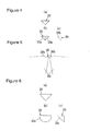
Fig. 4] Figs. 4(a) to 4(c) show a reflector of the human body detecting device according to the embodiment, wherein (a) is a plan view, (b) is a front view, and (c) is a right side view of the reflector. - [
Fig. 5] Fig. 5 is an explanatory diagram for describing a state in which the reflector according to the embodiment reflects a radio wave. - [
Fig. 6] Figs. 6(a) to 6(c) show a reflector in another embodiment, where (a) is a plan view, (b) is a front view, and (c) is a right side view of the reflector. - [
Fig. 7] Fig. 7 is a side cross-sectional view showing a reflector in yet another embodiment. - [
Fig. 8] Figs. 8(a) to 8(b) show a human body detecting device according to a second embodiment, wherein (a) is a side cross-sectional view, and (b) is a horizontal cross-sectional view. - [
Fig. 9] Figs. 9(a) to 9(c) show a reflector of the human body detecting device according to the second embodiment, where (a) is a plan view, (b) is a front view, and (c) is a right side view of the reflector. - [
Fig. 10] Fig. 10 is an explanatory diagram for describing a state in which the reflector according to the second embodiment reflects a radio wave. - [
Fig. 11] Figs. 11(a) to 11(c) show a reflector of the human body detecting device according to a third embodiment, where (a) is a plan view, (b) is a front view, and (c) is a right side view of the reflector. - In a first embodiment, a wireless human body detecting device 2 detecting presence of a person using a radio wave will be described (see
Fig. 1 ). A human body detecting device 2 is attached to a lighting device 1 shown inFig. 2 , and controls a lighting state of the lighting device 1 according to presence or absence of a person as described later. - The lighting device 1 includes a fixture
main body 11 formed into a box having an open front and accommodating therein a light source (not shown) and the human body detecting device 2. Anillumination cover 12 made of a translucent (for example, transparent) synthetic resin material and formed into a plate shape is attached to a front surface of the fixturemain body 11 longitudinally to a thickness direction. - As shown in
Fig. 1 , the human body detecting device 2 includes a sensormain body 20 emitting a radio wave, and areflector 30 arranged on a front surface of the sensormain body 20, and reflecting a part of the radio wave emitted by the sensormain body 20. Thereflector 30 will be described later. - In this embodiment, a Doppler-type sensor that detects presence of a person using the Doppler effect will be described as an example of the sensor
main body 20. That is, the sensormain body 20 determines whether or not a person is present according to a difference between a frequency of the emitted radio wave and that of the received radio wave using the fact that the frequency of the radio wave reflected by a moving object changes from that of the radio wave before being reflected. - As shown in
Fig. 3 , the sensormain body 20 includes amillimeter wave sensor 21 that emits a radio wave, receives the radio wave, and that outputs an IF signal with a frequency (so-called Doppler frequency) that is the difference between the frequency of the emitted radio wave and the received radio wave, anamplifier circuit 22 that amplifies the IF signal, and acontrol circuit 23 that determines whether or not a person is present according to the IF signal and that controls a lighting state of the lighting device 1. - A configuration of the
millimeter wave sensor 21 is not described in detail. However, for example, themillimeter wave sensor 21 is configured to include an oscillator circuit, a transmitting antenna connected to an output side of the oscillator circuit, a receiving antenna receiving a radio wave reflected by a human body or the like, and a mixer circuit to which an output from the oscillator circuit and an output from the receiving antenna are inputted. - An output frequency of the oscillator circuit is set so that the transmitting antenna emits a millimeter wave. In addition, directivity of the transmitting antenna is set so that the transmitting antenna emits a radio wave forward. Degree of the directivity is decided by design. For example, the degree of the directivity is decided so that the transmitting antenna emits a radio wave at intensity set by design to fall in a range of open angles from -30 degrees to +30 degrees with respect to a line passing the sensor
main body 20 along a longitudinal direction in a cross section including the line. - As the transmitting antenna, a horn antenna, for example, is used. As the receiving antenna, a pattern antenna formed using a conductor pattern of a printed wiring board, for example, is used.
- The
amplifier circuit 22 includes an amplifier using an operational amplifier and amplifies the IF signal. As theamplifier circuit 22, a filter-added amplifier circuit including a noise filter that eliminates components other than frequency components of the IF signal is used. Alternatively, the amplifier is configured to amplify only the frequency components of the IF signal. - The
control circuit 23 compares a detection signal that is the amplified IF signal with a predetermined threshold, outputs a determination result of "0" if the detection signal is lower than the threshold, and outputs a determination result of "1" if the signal is equal to or higher than the threshold. - If the determination result is "1" and the light source is not lighted, the
control circuit 23 inputs a lighting signal to a fixturemain body part 13 including a lighting device lighting the light source to light the light source (not shown). In this case, thedetermination circuit 23 includes a clock function and starts measuring time when outputting the lighting signal. When the measured time reaches predetermined lighting keeping time, thecontrol circuit 23 inputs a lighting-off signal to the fixturemain body part 13 to light off the light source. The predetermined lighting holding time is, for example, set in advance. - If the determination result is "1" and the light source is lighted, the
control circuit 23 resets the measured time to zero and measures time again. That is, the human body detecting device 2 lights off the light source while detecting presence of a person and lights off the light source after passage of the predetermined time (lighting keeping time) since the human body detecting device 2 does not detect the presence of a person. If the determination result is "0", thecontrol circuit 23 does not output any signal. - The
reflector 30 arranged in front of the sensormain body 20 will next be described. Thereflector 30 is made of a metallic material. As shown inFig. 4 , thereflector 30 is formed to be generally identical in shape to a triangular pyramid obtained by dividing a square pyramid having a height half as large as a length of a diagonal line of a bottom of the square pyramid by a plane including a central axis and the diagonal line of the (square) bottom. That is, the reflector is formed into a bilaterally symmetric triangular pyramid having a bottom and one of side surfaces that are right-angled isosceles triangles having hypotenuses orthogonal to each other, and remaining twoside surfaces - As shown in
Fig. 1 , thereflector 30 is attached to anillumination cover 12 in front of the sensormain body 20 while abutting the bottom of thereflector 30 on a rear surface of theillumination cover 12, and the side surfaces 30a and 30b of thereflector 30 reflect a part of a radio wave emitted from the sensormain body 20. - Therefore, a first area D1 that is a space in front of the illumination device 1 and a second area D2 that is a space irradiated with the radio wave reflected by the
reflector 30 can be set to detection areas, respectively. Further, since the second area D2 is set to the detection area by the radio wave reflected by thereflector 30, it is possible to suppress deterioration of front sensitivity as compared with an instance of setting the second area D2 to the detection area by lowering directivity. - How the human body detecting device 2 detects presence of a person will be described while referring to an example of installing the illumination device 1 to which the human body detecting device 2 according to this embodiment is attached on a doglegged staircase A shown in
Fig. 2 . The doglegged staircase A includes a halfpace B, stairs C1 rising from the halfpace B, stairs C2 lowering from the halfpace B, and a wall W in front of which the stairs C1 and C2 are present. The illumination device 1 is installed onto the wall W (at a position, for example, 2 m from a floor of the halfpace B) so that the stairs C1 and C2 are located in front of the illumination device 1. That is, the first area D1 set to the detection area by the human body detecting device 1 includes the stairs C1 and C2 and the halfpace B except for a part of the halfpace B against the wall onto which the illumination device 1 is installed. - Directions of the side surfaces 30a and 30b of the
reflector 30 are set to emit the reflected radio wave to the part of the halfpace B against the wall. That is, the second area D2 that is not shown inFig. 2 but shown inFig. 1 includes the part of the halfpace B against the wall. - Accordingly, the detection area is set to an area including the stairs C1 and C2 and the halfpace B (including the part of the halfpace B against the wall), and the human body detecting device 2 can detect a person present in the stair C1 or C2 or the halfpace B (including the part of the halfpace B against the wall).
- Meanwhile, a radio wave refracted by an end of the
reflector 30 is emitted to an area in front of thereflector 30. However, an area E having low sensitivity is generated near thereflector 30. In this embodiment, thereflector 30 is arranged in front of the sensormain body 20, and a magnitude of thereflector 30 is set to be almost equal to or smaller than that of an antenna surface of the transmitting antenna from which surface the radio wave is emitted. This prevents the area E from being made excessively long in a longitudinal direction even if a distance between the sensormain body 20 and thereflector 30 is set short (to, for example, 10 cm). - While the configuration of forming the
reflector 30 into a shape of the triangular pyramid has been described, the shape of thereflector 30 is not limited to the triangular pyramid. However, thereflector 30 can be formed into a shape of a triangular pyramid having an open bottom. As shown inFig. 6 , thereflector 30 can be formed into a shape obtained by dividing a cone by a plane including a central axis. If thereflector 30 is formed into the shape obtained by dividing the cone by the plane including the central axis, acurved surface 30c of thereflector 30 reflects the radio wave emitted from the transmitting antenna. - In another alternative, the
reflector 30 can be attached to theillumination cover 12 in such a fashion as to be buried in theillumination cover 12 as shown inFig. 7 . For example, a fitting concave portion into which thereflector 30 is fitted is provided in theillumination cover 12. - In the first embodiment, the configuration of arranging the
reflector 30 in front of the sensormain body 20 has been described. In this embodiment, a configuration of arranging thereflector 30 in a portion other than a portion in front of the sensormain body 20 will be described as shown inFig. 8 . - In this embodiment, the
reflector 30 is formed into a triangular pyramid having a bottom and one side surface that are orthogonal to each other as shown inFig. 9 . As shown inFig. 8 , thereflector 30 is arranged at a position other than that in front of the sensormain body 20 so that the bottom of thereflector 30 abuts on theillumination cover 12. - The position of the
reflector 30 is defined by an angle θ1 formed between a line passing through the sensormain body 20 along the longitudinal direction and a line connecting the sensormain body 20 to thereflector 30 if the human body detecting device 2 is viewed from a direction orthogonal to a vertical direction and the longitudinal direction (seeFig. 8(a) ), and an angle θ2 formed between a line passing through the sensormain body 20 along the longitudinal direction and a line connecting the sensormain body 20 to thereflector 30 if the human body detecting device 2 is viewed from upward (seeFig. 8(b) ). - The angles θ1 and θ2 are set so that the
reflector 30 reflects radio waves emitted toward a space where there is no need to detect presence of a person. - For example, if the illumination device 1 is disposed on the doglegged staircase A as described in the first embodiment, the angles θ1 and θ2 are set so that the
reflector 30 reflects a radio wave emitted upward of the stairs C2 lowering from the halfpace B. Specifically, as shown inFig. 10 , thereflector 30 is arranged upper right of the sensormain body 20. - In this embodiment, directions of the side surfaces 30a and 30b of the
reflector 30 are set so that the radio wave reflected by theside surface reflector 30 is arranged, and thereflector 30 is formed asymmetrically. - In this embodiment, the second area D2 can be set to the detection area using the radio wave irradiated toward the space where there is no need to detect presence of a person. It is, therefore, possible to efficiently use emitted radio waves.
- The other configurations of the human body detecting device 2 according to this embodiment are similar to those according to the first embodiment.
- In the first embodiment, the configuration of the human body detecting device 2 in which the
reflector 30 formed into the shape of the triangular pyramid reflects the radio wave has been described. In this embodiment, a configuration of a human body detecting device in which thereflector 30 that is a meshed reflector reflects a radio wave will be described as shown inFig. 11 . - The
reflector 30 is formed to have a triangular pyramid external shape identical to an external shape of thereflector 30 using a wire net having square meshes. A length L of a side of each mesh is set to be (for example, 5 mm) smaller than a half-wavelength 6.2 mm of the radio wave emitted by the reflectormain body 20. That is, thereflector 30 includes a function of an electromagnetic shield that shields transmission of the radio wave emitted from the transmitting antenna. The radio wave shielded from being transmitted by thereflector 30 changes a direction on the side surfaces 30a and 30b of thereflector 30 and is irradiated onto the second area D2. - By forming the
reflector 30 into the meshed reflector, thereflector 30 can transmit light from a light source (not shown). As compared with the first and second embodiments, shades of thereflector 30 generated on theillumination cover 12 by the light from the light source can be reduced. - While the
reflector 30 is formed using the wire net in this embodiment, thereflector 30 can be formed using a metal plate into which many holes are formed by punching out the holes. - In this embodiment, the configuration of the human body detecting device in which the
reflector 30 is arranged in front of the sensormain body 20 has been described. Thereflector 30 can be arranged at a position other than that in front of the sensormain body 20 similarly to the second embodiment. - The other configurations of the human body detecting device according to this embodiment are similar to those according to the first embodiment.
-
- 2
- Human body detecting device
- 20
- Sensor main body
- 30, 31
- Reflector
- 32
- Reflector (mesh)
- D1
- First area
- D2
- Second area
Claims (3)
- A human body detecting device comprising:a sensor main body emitting a radio wave toward a first area in front of the sensor main body, receiving the radio wave, and determining whether a person is present according to relationship between the emitted radio wave and the received radio wave; anda reflector reflecting a part of the radio wave emitted by the sensor main body, wherein:the reflector reflects the radio wave toward a second area other than the first area in front of the sensor main body.
- The human body detecting device according to claim 1, wherein:the reflector is made of a metallic material.
- The human body detecting device according to claim 2, wherein:the reflector is a meshed reflector.
Applications Claiming Priority (1)
| Application Number | Priority Date | Filing Date | Title |
|---|---|---|---|
| JP2009175900A JP2011027651A (en) | 2009-07-28 | 2009-07-28 | Human body detection device |
Publications (2)
| Publication Number | Publication Date |
|---|---|
| EP2280289A2 true EP2280289A2 (en) | 2011-02-02 |
| EP2280289A3 EP2280289A3 (en) | 2011-12-14 |
Family
ID=43034115
Family Applications (1)
| Application Number | Title | Priority Date | Filing Date |
|---|---|---|---|
| EP10170993A Ceased EP2280289A3 (en) | 2009-07-28 | 2010-07-28 | Human body detecting device |
Country Status (2)
| Country | Link |
|---|---|
| EP (1) | EP2280289A3 (en) |
| JP (1) | JP2011027651A (en) |
Cited By (1)
| Publication number | Priority date | Publication date | Assignee | Title |
|---|---|---|---|---|
| EP2669702A1 (en) * | 2012-06-01 | 2013-12-04 | Panasonic Corporation | Sensor device |
Citations (4)
| Publication number | Priority date | Publication date | Assignee | Title |
|---|---|---|---|---|
| GB2046552A (en) * | 1979-04-04 | 1980-11-12 | Loadpoint Ltd | Improvements in radar detection devices |
| JP2002285624A (en) | 2001-03-26 | 2002-10-03 | Toto Ltd | Toilet device |
| EP1394564A2 (en) * | 2002-08-27 | 2004-03-03 | Omron Corporation | Intruding object detecting apparatus with variable detection region and calibration process |
| US20050270227A1 (en) * | 2003-07-03 | 2005-12-08 | Stephens Scott A | Positioning system with intentional multi-path signal |
Family Cites Families (2)
| Publication number | Priority date | Publication date | Assignee | Title |
|---|---|---|---|---|
| US3911443A (en) * | 1973-11-28 | 1975-10-07 | Johnson Service Co | Split beam antenna apparatus for developing angularly oriented beams |
| GB2312992A (en) * | 1996-05-10 | 1997-11-12 | Pyronix Ltd | Doppler microwave event detection device |
-
2009
- 2009-07-28 JP JP2009175900A patent/JP2011027651A/en not_active Withdrawn
-
2010
- 2010-07-28 EP EP10170993A patent/EP2280289A3/en not_active Ceased
Patent Citations (4)
| Publication number | Priority date | Publication date | Assignee | Title |
|---|---|---|---|---|
| GB2046552A (en) * | 1979-04-04 | 1980-11-12 | Loadpoint Ltd | Improvements in radar detection devices |
| JP2002285624A (en) | 2001-03-26 | 2002-10-03 | Toto Ltd | Toilet device |
| EP1394564A2 (en) * | 2002-08-27 | 2004-03-03 | Omron Corporation | Intruding object detecting apparatus with variable detection region and calibration process |
| US20050270227A1 (en) * | 2003-07-03 | 2005-12-08 | Stephens Scott A | Positioning system with intentional multi-path signal |
Cited By (2)
| Publication number | Priority date | Publication date | Assignee | Title |
|---|---|---|---|---|
| EP2669702A1 (en) * | 2012-06-01 | 2013-12-04 | Panasonic Corporation | Sensor device |
| US9185779B2 (en) | 2012-06-01 | 2015-11-10 | Panasonic Intellectual Property Management Co., Ltd. | Sensor device for reducing erroneous activation of a light source |
Also Published As
| Publication number | Publication date |
|---|---|
| JP2011027651A (en) | 2011-02-10 |
| EP2280289A3 (en) | 2011-12-14 |
Similar Documents
| Publication | Publication Date | Title |
|---|---|---|
| JP6695059B2 (en) | lighting equipment | |
| US4517566A (en) | True ground speed sensor | |
| JP2018017552A (en) | Radar equipment | |
| EP3961248A1 (en) | Terminal | |
| JP7660329B2 (en) | Light source unit and lighting fixture | |
| EP3769428B1 (en) | Ultrasonic proximity sensing for sar mitigation | |
| JP6975923B2 (en) | lighting equipment | |
| JP5360950B2 (en) | lighting equipment | |
| JP6861372B2 (en) | Radio sensor and lighting equipment | |
| JP4117688B1 (en) | Urinal equipment | |
| CN101725855B (en) | Illumination apparatus | |
| US20110226952A1 (en) | Reflection Sensing System | |
| EP2280289A2 (en) | Human body detecting device | |
| US20190063746A1 (en) | Flame detector with signal collector and focuser | |
| US20180131090A1 (en) | Radio wave sensor and luminaire | |
| AU2015202515B2 (en) | Radar obstacle detector for a railway crossing | |
| JP2012112745A (en) | Lighting fixture with doppler sensor | |
| US8618999B2 (en) | Microwave motion sensor with a reflector | |
| JP6379833B2 (en) | Antenna device | |
| CN101836127B (en) | Ultrasonic sensing device combined with adjustable horn structure | |
| JP2019120571A (en) | Water level meter and tank | |
| CN114442069A (en) | Laser detection module and laser radar | |
| JP2012113904A (en) | Lighting fixture with doppler sensor | |
| JP5559959B2 (en) | Detection system | |
| JP2011243463A (en) | Lighting fixture, and illumination system using the same |
Legal Events
| Date | Code | Title | Description |
|---|---|---|---|
| PUAI | Public reference made under article 153(3) epc to a published international application that has entered the european phase |
Free format text: ORIGINAL CODE: 0009012 |
|
| AK | Designated contracting states |
Kind code of ref document: A2 Designated state(s): AL AT BE BG CH CY CZ DE DK EE ES FI FR GB GR HR HU IE IS IT LI LT LU LV MC MK MT NL NO PL PT RO SE SI SK SM TR |
|
| AX | Request for extension of the european patent |
Extension state: BA ME RS |
|
| PUAL | Search report despatched |
Free format text: ORIGINAL CODE: 0009013 |
|
| AK | Designated contracting states |
Kind code of ref document: A3 Designated state(s): AL AT BE BG CH CY CZ DE DK EE ES FI FR GB GR HR HU IE IS IT LI LT LU LV MC MK MT NL NO PL PT RO SE SI SK SM TR |
|
| AX | Request for extension of the european patent |
Extension state: BA ME RS |
|
| RIC1 | Information provided on ipc code assigned before grant |
Ipc: H01Q 19/10 20060101ALI20111110BHEP Ipc: G01S 13/56 20060101ALI20111110BHEP Ipc: G01S 7/40 20060101AFI20111110BHEP |
|
| RAP1 | Party data changed (applicant data changed or rights of an application transferred) |
Owner name: PANASONIC CORPORATION |
|
| 17P | Request for examination filed |
Effective date: 20120614 |
|
| 17Q | First examination report despatched |
Effective date: 20120809 |
|
| 17Q | First examination report despatched |
Effective date: 20120820 |
|
| RAP1 | Party data changed (applicant data changed or rights of an application transferred) |
Owner name: PANASONIC INTELLECTUAL PROPERTY MANAGEMENT CO., LT |
|
| STAA | Information on the status of an ep patent application or granted ep patent |
Free format text: STATUS: THE APPLICATION HAS BEEN REFUSED |
|
| 18R | Application refused |
Effective date: 20160925 |