EP2280169A2 - Airless spray pump - Google Patents
Airless spray pump Download PDFInfo
- Publication number
- EP2280169A2 EP2280169A2 EP10184231A EP10184231A EP2280169A2 EP 2280169 A2 EP2280169 A2 EP 2280169A2 EP 10184231 A EP10184231 A EP 10184231A EP 10184231 A EP10184231 A EP 10184231A EP 2280169 A2 EP2280169 A2 EP 2280169A2
- Authority
- EP
- European Patent Office
- Prior art keywords
- pump
- gear
- assembly
- housing
- spray pump
- Prior art date
- Legal status (The legal status is an assumption and is not a legal conclusion. Google has not performed a legal analysis and makes no representation as to the accuracy of the status listed.)
- Granted
Links
- 239000007921 spray Substances 0.000 title claims abstract description 16
- 238000012856 packing Methods 0.000 description 6
- 239000000314 lubricant Substances 0.000 description 4
- 238000004519 manufacturing process Methods 0.000 description 4
- 230000000717 retained effect Effects 0.000 description 3
- 238000000576 coating method Methods 0.000 description 2
- 238000013461 design Methods 0.000 description 2
- 238000005553 drilling Methods 0.000 description 2
- 230000005484 gravity Effects 0.000 description 2
- 239000003973 paint Substances 0.000 description 2
- 238000005086 pumping Methods 0.000 description 2
- 239000002904 solvent Substances 0.000 description 2
- 238000005507 spraying Methods 0.000 description 2
- 238000012546 transfer Methods 0.000 description 2
- 238000000034 method Methods 0.000 description 1
- 238000012986 modification Methods 0.000 description 1
- 230000004048 modification Effects 0.000 description 1
- XLYOFNOQVPJJNP-UHFFFAOYSA-N water Substances O XLYOFNOQVPJJNP-UHFFFAOYSA-N 0.000 description 1
Images


Classifications
-
- F—MECHANICAL ENGINEERING; LIGHTING; HEATING; WEAPONS; BLASTING
- F04—POSITIVE - DISPLACEMENT MACHINES FOR LIQUIDS; PUMPS FOR LIQUIDS OR ELASTIC FLUIDS
- F04C—ROTARY-PISTON, OR OSCILLATING-PISTON, POSITIVE-DISPLACEMENT MACHINES FOR LIQUIDS; ROTARY-PISTON, OR OSCILLATING-PISTON, POSITIVE-DISPLACEMENT PUMPS
- F04C2/00—Rotary-piston machines or pumps
- F04C2/08—Rotary-piston machines or pumps of intermeshing-engagement type, i.e. with engagement of co-operating members similar to that of toothed gearing
- F04C2/12—Rotary-piston machines or pumps of intermeshing-engagement type, i.e. with engagement of co-operating members similar to that of toothed gearing of other than internal-axis type
- F04C2/14—Rotary-piston machines or pumps of intermeshing-engagement type, i.e. with engagement of co-operating members similar to that of toothed gearing of other than internal-axis type with toothed rotary pistons
-
- F—MECHANICAL ENGINEERING; LIGHTING; HEATING; WEAPONS; BLASTING
- F04—POSITIVE - DISPLACEMENT MACHINES FOR LIQUIDS; PUMPS FOR LIQUIDS OR ELASTIC FLUIDS
- F04B—POSITIVE-DISPLACEMENT MACHINES FOR LIQUIDS; PUMPS
- F04B9/00—Piston machines or pumps characterised by the driving or driven means to or from their working members
- F04B9/02—Piston machines or pumps characterised by the driving or driven means to or from their working members the means being mechanical
-
- F—MECHANICAL ENGINEERING; LIGHTING; HEATING; WEAPONS; BLASTING
- F04—POSITIVE - DISPLACEMENT MACHINES FOR LIQUIDS; PUMPS FOR LIQUIDS OR ELASTIC FLUIDS
- F04B—POSITIVE-DISPLACEMENT MACHINES FOR LIQUIDS; PUMPS
- F04B17/00—Pumps characterised by combination with, or adaptation to, specific driving engines or motors
- F04B17/03—Pumps characterised by combination with, or adaptation to, specific driving engines or motors driven by electric motors
-
- F—MECHANICAL ENGINEERING; LIGHTING; HEATING; WEAPONS; BLASTING
- F04—POSITIVE - DISPLACEMENT MACHINES FOR LIQUIDS; PUMPS FOR LIQUIDS OR ELASTIC FLUIDS
- F04B—POSITIVE-DISPLACEMENT MACHINES FOR LIQUIDS; PUMPS
- F04B53/00—Component parts, details or accessories not provided for in, or of interest apart from, groups F04B1/00 - F04B23/00 or F04B39/00 - F04B47/00
- F04B53/16—Casings; Cylinders; Cylinder liners or heads; Fluid connections
- F04B53/162—Adaptations of cylinders
- F04B53/166—Cylinder liners
- F04B53/168—Mounting of cylinder liners in cylinders
-
- F—MECHANICAL ENGINEERING; LIGHTING; HEATING; WEAPONS; BLASTING
- F04—POSITIVE - DISPLACEMENT MACHINES FOR LIQUIDS; PUMPS FOR LIQUIDS OR ELASTIC FLUIDS
- F04B—POSITIVE-DISPLACEMENT MACHINES FOR LIQUIDS; PUMPS
- F04B9/00—Piston machines or pumps characterised by the driving or driven means to or from their working members
- F04B9/02—Piston machines or pumps characterised by the driving or driven means to or from their working members the means being mechanical
- F04B9/04—Piston machines or pumps characterised by the driving or driven means to or from their working members the means being mechanical the means being cams, eccentrics or pin-and-slot mechanisms
- F04B9/045—Piston machines or pumps characterised by the driving or driven means to or from their working members the means being mechanical the means being cams, eccentrics or pin-and-slot mechanisms the means being eccentrics
Definitions
- Airless spray pumps for the spraying of paints and other coatings.
- Airless spray pumps for the spraying of paints and other coatings via the airless method are well known and have traditionally been divided into two types, diaphragm pumps for the lower end of the market and reciprocating piston pumps for the higher end.
- An airless spray pump is provided with a single-acting piston pump which allows the use of a low-cost yoke drive. Motor and pump shaft are offset for most efficient force utilization.
- the main drive housing has a motor mounted to the rear thereof.
- a gear assembly uses gear teeth which are formed with a 5° helical angle and have a 25° pressure angle. This geometry combines the higher efficiency of straight cut gears with the noise reduction typified in a helical design.
- An eccentric is molded onto the front of the gear assembly and has located thereabout a bearing assembly which rides inside a yoke.
- the yoke moves vertically on guide rods which are retained in pockets of the drive housing.
- the yoke is molded of plastic as is the gear assembly leading to lower cost and easier manufacture.
- the pump rod is provided with a cap over the top end thereof which has bearing.
- Pump assembly is designed as a single acting pump, that is, the pump only pumps on the downward stroke and loads on the upward stroke. This allows the components of the drive train, including the yoke and gear, to be much lighter as the yoke ends up being more of a guidance device rather than a force-applying device.
- the motor and pinion are offset from the centerline of the pump assembly. This arrangement does not have any significant cantilevering as the pump rod, pinion, yoke, eccentric and cap are all located in the same plane.
- the location of the rod and the single acting pump with respect to the gear centerline reduces the thrust loads on the yoke.
- the location of the pinion on the gear partially offsets and reduces the pump forces on the gear shaft and bearings.
- the shaft packing assembly is comprised of a packing housing which screws into the pump housing and which contains a felt member which has been soaked with throat seal lubricant or other solvent or lubricant.
- a stack of v-packings are compressed in place by wave spring which is tightened by tightening the seal housing into the pump housing .
- the inlet check is provided with a check ball and a check seat which is pressed into a check housing and which is held in place by a retainer. These parts all press-fit into one another such that the complete assembly be merely screwed into main pump housing for replacement.
- outlet check assembly is formed of an outlet check housing which is screwed into a pump housing and similarly is provided with a check ball held in place by a retainer.
- the outlet passageway is angled relative to the axis of the pump shaft. This allows the outlet check assembly to operate essentially via gravity and yet requires only the drilling and provision of one passageway while maintaining an essentially vertical ball-seat relationship.
- the instant invention generally designated 10 is comprised of a main drive housing 12 having a motor 14 mounted to the rear thereof.
- a gear assembly 16 having a rear bearing 17 and gear teeth 22 is inserted into the bearing housing 20 of drive housing 12.
- Gear teeth 22 on gear assembly 16 mate with the teeth on pinion 24 on the end of motor 14.
- the teeth 22 and on pinion 24 are formed with a 5° helical angle and have a 25° pressure angle. This geometry combines the higher efficiency of straight cut gears with the noise reduction typified in a helical design.
- An eccentric 25 is also molded onto the front of gear assembly 16 and has located thereabout a bearing assembly 28 which rides inside a yoke 30.
- Yoke 30 moves vertically on guide rods 32 which are retained in pockets 34 of drive housing 12.
- Yoke 30 is molded of plastic.
- Gear assembly 16 is cast in ZA-12 with an integral counterweight leading to lower cost and easier manufacture.
- Pump rod 36 is provided with a cap 38 over the top end thereof which has bearing upon it bearing 28.
- Pump assembly 40 is designed as a single acting pump that is the pump only pumps on the downward stroke and loads on the upward stroke. In doing so this allows the components of the drive train, including the yoke and gear, to be much lighter as the yoke 30 ends up being more of a guidance device rather than a force-applying device.
- motor and pinion 24 are offset from the centerline 42 of pump assembly 40 which also has offset therefrom bearing 20 in the opposite direction. Also, this arrangement does not have any significant cantilevering as the pump rod, pinion, yoke, eccentric and cap are all located in the same plane.
- the location of the rod and the single acting pump with respect to the gear centerline reduces the thrust loads on the yoke.
- the location of the pinion on the gear partially offsets and reduces the pump forces on the gear shaft and bearings.
- the shaft packing assembly 44 shown in FIG. 4 is comprised of a packing housing 46 which screws into pump housing 48 and which contains a felt member 50 which has been soaked with throat seal lubricant or other solvent or lubricant.
- a stack of v-packings 52 are compressed in place by wave spring 54 which is tightened by tightening seal housing 46 into pump housing 48.
- inlet check 56 is provided with a check ball 58, a check seat 60 which is pressed into check housing 62 and which is held in place by retainer and integral ball guide 64. These parts all press-fit into one another such that the complete assembly be merely screwed into main pump housing 48 for replacement.
- outlet check assembly is formed of an outlet check housing 60 which is screwed into pump housing 48 and similarly is provided with a check ball 62 held in place by ball seat 65.
- the outlet passageway 66 is angled relative to the axis of pump shaft 36. This allows the outlet check assembly 58 to operate essentially via gravity and yet requires only the drilling and provision of one passageway while maintaining an essentially vertical ball-seat relationship.
- FIGs. 8 and 9 show the outlet filter assembly 80 which is comprised of a filter element 82 contained in passage 84 of pump assembly 40 and which is retained by fitting 86.
- inlet tube 70 is provided with a female threaded end 70a.
- Inlet filter screen assembly 72 has a male threaded end 72a for threaded engagement with end 70a. Ends 70a and 72a use the same size and thread as a common garden hose such that a user need merely remove screen assembly 72, attach a garden hose to inlet tube 70, turn on the water and flush out the assembly.
Landscapes
- Engineering & Computer Science (AREA)
- Mechanical Engineering (AREA)
- General Engineering & Computer Science (AREA)
- Reciprocating Pumps (AREA)
- Details Of Reciprocating Pumps (AREA)
- Applications Or Details Of Rotary Compressors (AREA)
Abstract
Description
- Airless spray pumps for the spraying of paints and other coatings.
- Airless spray pumps for the spraying of paints and other coatings via the airless method are well known and have traditionally been divided into two types, diaphragm pumps for the lower end of the market and reciprocating piston pumps for the higher end.
- An airless spray pump is provided with a single-acting piston pump which allows the use of a low-cost yoke drive. Motor and pump shaft are offset for most efficient force utilization. The main drive housing has a motor mounted to the rear thereof. A gear assembly uses gear teeth which are formed with a 5° helical angle and have a 25° pressure angle. This geometry combines the higher efficiency of straight cut gears with the noise reduction typified in a helical design.
- An eccentric is molded onto the front of the gear assembly and has located thereabout a bearing assembly which rides inside a yoke. The yoke moves vertically on guide rods which are retained in pockets of the drive housing. The yoke is molded of plastic as is the gear assembly leading to lower cost and easier manufacture.
- The pump rod is provided with a cap over the top end thereof which has bearing. Pump assembly is designed as a single acting pump, that is, the pump only pumps on the downward stroke and loads on the upward stroke. This allows the components of the drive train, including the yoke and gear, to be much lighter as the yoke ends up being more of a guidance device rather than a force-applying device.
- The motor and pinion are offset from the centerline of the pump assembly. This arrangement does not have any significant cantilevering as the pump rod, pinion, yoke, eccentric and cap are all located in the same plane. The location of the rod and the single acting pump with respect to the gear centerline reduces the thrust loads on the yoke. The location of the pinion on the gear partially offsets and reduces the pump forces on the gear shaft and bearings. By locating the eccentric bearing directly on the end of the pump rod cap which is press-fit it eliminates the transfer of pumping force through an intermediate member such as the yoke which provides longer life, efficiency and allows the manufacture of a more inexpensive yoke assembly.
- The shaft packing assembly is comprised of a packing housing which screws into the pump housing and which contains a felt member which has been soaked with throat seal lubricant or other solvent or lubricant. A stack of v-packings are compressed in place by wave spring which is tightened by tightening the seal housing into the pump housing .
- The inlet check is provided with a check ball and a check seat which is pressed into a check housing and which is held in place by a retainer. These parts all press-fit into one another such that the complete assembly be merely screwed into main pump housing for replacement. Similarly, outlet check assembly is formed of an outlet check housing which is screwed into a pump housing and similarly is provided with a check ball held in place by a retainer. The outlet passageway is angled relative to the axis of the pump shaft. This allows the outlet check assembly to operate essentially via gravity and yet requires only the drilling and provision of one passageway while maintaining an essentially vertical ball-seat relationship.
- These and other objects and advantages of the invention will appear more fully from the following description made in conjunction with the accompanying drawings wherein like reference characters refer to the same or similar parts throughout the several views.
-
-
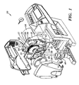
FIG. 1 is a prospective exploded view showing the airless spray pump with the instant invention. -
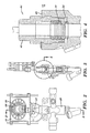
FIG. 2 is a simple front plan view of the drive assembly and pump of the instant invention. -
FIG. 3 is a side plan view of the assembly shown inFIG. 1 . -
FIG. 4 is a detailed exploded view of the circled area inFIG. 3 . -
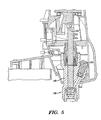
FIG. 5 is a cross-sectional view of the pump of the instant invention. -
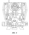
FIG. 6 shows more details of the drive assembly of the instant invention. -
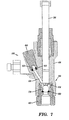
FIG. 7 is another cross-sectional view of the pump portion of the instant invention. -
FIG. 8 is a cross-section of the outlet filter of the instant invention. -
FIG. 9 is an exploded view of the outlet filter of the instant invention. -
FIG. 10 is a perspective exploded view of the instant invention. - The instant invention generally designated 10 is comprised of a
main drive housing 12 having amotor 14 mounted to the rear thereof. Agear assembly 16 having arear bearing 17 andgear teeth 22 is inserted into the bearinghousing 20 ofdrive housing 12.Gear teeth 22 ongear assembly 16 mate with the teeth onpinion 24 on the end ofmotor 14. Theteeth 22 and onpinion 24 are formed with a 5° helical angle and have a 25° pressure angle. This geometry combines the higher efficiency of straight cut gears with the noise reduction typified in a helical design. - An eccentric 25 is also molded onto the front of
gear assembly 16 and has located thereabout abearing assembly 28 which rides inside ayoke 30. Yoke 30 moves vertically onguide rods 32 which are retained inpockets 34 ofdrive housing 12. Yoke 30 is molded of plastic.Gear assembly 16 is cast in ZA-12 with an integral counterweight leading to lower cost and easier manufacture. -
Pump rod 36 is provided with acap 38 over the top end thereof which has bearing upon it bearing 28.Pump assembly 40 is designed as a single acting pump that is the pump only pumps on the downward stroke and loads on the upward stroke. In doing so this allows the components of the drive train, including the yoke and gear, to be much lighter as theyoke 30 ends up being more of a guidance device rather than a force-applying device. - As can be seen more particularly in
FIG. 2 , motor andpinion 24 are offset from thecenterline 42 ofpump assembly 40 which also has offset therefrom bearing 20 in the opposite direction. Also, this arrangement does not have any significant cantilevering as the pump rod, pinion, yoke, eccentric and cap are all located in the same plane. The location of the rod and the single acting pump with respect to the gear centerline reduces the thrust loads on the yoke. The location of the pinion on the gear partially offsets and reduces the pump forces on the gear shaft and bearings. By locating the eccentric bearing directly on the end of the pump rod cap which is press-fit it eliminates the transfer of pumping force through an intermediate member such as the yoke which provides longer life, efficiency and allows the manufacture of a more inexpensive yoke assembly. - The
shaft packing assembly 44 shown inFIG. 4 is comprised of apacking housing 46 which screws intopump housing 48 and which contains a feltmember 50 which has been soaked with throat seal lubricant or other solvent or lubricant. A stack of v-packings 52 are compressed in place bywave spring 54 which is tightened by tighteningseal housing 46 intopump housing 48. - Turning to
FIG. 7 ,inlet check 56 is provided with acheck ball 58, acheck seat 60 which is pressed intocheck housing 62 and which is held in place by retainer andintegral ball guide 64. These parts all press-fit into one another such that the complete assembly be merely screwed intomain pump housing 48 for replacement. Similarly, outlet check assembly is formed of anoutlet check housing 60 which is screwed intopump housing 48 and similarly is provided with acheck ball 62 held in place byball seat 65. As can also be seen inFIG. 7 , theoutlet passageway 66 is angled relative to the axis ofpump shaft 36. This allows theoutlet check assembly 58 to operate essentially via gravity and yet requires only the drilling and provision of one passageway while maintaining an essentially vertical ball-seat relationship. -
FIGs. 8 and 9 show theoutlet filter assembly 80 which is comprised of afilter element 82 contained inpassage 84 ofpump assembly 40 and which is retained by fitting 86. - Turning to
FIG. 10 ,inlet tube 70 is provided with a female threadedend 70a. Inletfilter screen assembly 72 has a male threadedend 72a for threaded engagement withend 70a.Ends screen assembly 72, attach a garden hose toinlet tube 70, turn on the water and flush out the assembly. - It is contemplated that various changes and modifications may be made to the airless spray pump without departing from the scope of the invention as defined by the following claims.
Claims (9)
- A spray pump powered by a rotary motor having a pinion thereon and comprising:a housing (12);a single-acting piston pump (40) having a pump rod and connected to said housing;a drive gear assembly (16) comprising a gear and an eccentric (25) located on said gear;a bearing (28) located about said eccentric; anda yoke (30) reciprocatingly located in said housing and about said bearing,wherein said motor and pinion are offset from a centreline of said pump to reduce thrust loads on the yoke and offset and reduce pump forces.
- The spray pump of claim 1, wherein the gear is rotatable about a gear centreline, wherein said gear centreline is offset from the centreline of said pump.
- The spray pump of claim 1 or claim 2, wherein said pump rod, said pinion, said yoke and said eccentric are all located in generally the same plane.
- The spray pump of any one of the preceding claims, wherein the teeth on said gear are formed with about a 5° helical angle and about a 25 ° pressure angle.
- The spray pump of any one of the preceding claims, wherein the pinion is driven by the motor and engages teeth of the gear to rotate the gear and the eccentric about the gear centreline.
- The spray pump of any one of the preceding claims, wherein the single-acting piston pump is arranged to pump up on a downward stroke and to load on an upward stroke of the pump rod.
- The spray pump of claim 6, wherein the pump rod is aligned with the centreline of the pump.
- The spray pump of any one of the preceding claims, wherein the eccentric is integral with a front of the gear assembly.
- The spray pump of any one of the preceding claims, wherein the motor is mounted to the rear portion of the housing.
Applications Claiming Priority (4)
| Application Number | Priority Date | Filing Date | Title |
|---|---|---|---|
| US15179499P | 1999-08-31 | 1999-08-31 | |
| US16694699P | 1999-11-22 | 1999-11-22 | |
| EP05077480A EP1635062B1 (en) | 1999-08-31 | 2000-08-28 | Airless spray pump |
| EP00961390A EP1208287B1 (en) | 1999-08-31 | 2000-08-28 | Airless spray pump |
Related Parent Applications (2)
| Application Number | Title | Priority Date | Filing Date |
|---|---|---|---|
| EP00961390.2 Division | 2000-08-28 | ||
| EP05077480.1 Division | 2005-10-31 |
Publications (3)
| Publication Number | Publication Date |
|---|---|
| EP2280169A2 true EP2280169A2 (en) | 2011-02-02 |
| EP2280169A3 EP2280169A3 (en) | 2011-12-07 |
| EP2280169B1 EP2280169B1 (en) | 2013-05-01 |
Family
ID=26848977
Family Applications (2)
| Application Number | Title | Priority Date | Filing Date |
|---|---|---|---|
| EP00961390A Expired - Lifetime EP1208287B1 (en) | 1999-08-31 | 2000-08-28 | Airless spray pump |
| EP10184231.8A Expired - Lifetime EP2280169B1 (en) | 1999-08-31 | 2000-08-28 | Airless spray pump |
Family Applications Before (1)
| Application Number | Title | Priority Date | Filing Date |
|---|---|---|---|
| EP00961390A Expired - Lifetime EP1208287B1 (en) | 1999-08-31 | 2000-08-28 | Airless spray pump |
Country Status (9)
| Country | Link |
|---|---|
| US (1) | USRE42706E1 (en) |
| EP (2) | EP1208287B1 (en) |
| JP (2) | JP4668493B2 (en) |
| KR (1) | KR100668583B1 (en) |
| CN (1) | CN1171004C (en) |
| AU (1) | AU7334800A (en) |
| DE (1) | DE60029597T2 (en) |
| ES (3) | ES2424141T3 (en) |
| WO (1) | WO2001016462A1 (en) |
Families Citing this family (6)
| Publication number | Priority date | Publication date | Assignee | Title |
|---|---|---|---|---|
| CN1232332C (en) * | 2001-06-05 | 2005-12-21 | 格雷科明尼苏达有限公司 | Integrated filter housing |
| EP2457666A1 (en) * | 2010-11-25 | 2012-05-30 | Doriano Galassi | Spray painting device |
| CN205586102U (en) * | 2014-12-01 | 2016-09-21 | 洁碧有限公司 | Waterproof wireless oral cavity flusher |
| AU2017200180B2 (en) * | 2016-01-12 | 2022-01-06 | Graco Minnesota Inc. | Integrated pump guard and control interlock |
| US12140140B2 (en) * | 2016-07-29 | 2024-11-12 | Wagner Spray Tech Corporation | Aligning reciprocating motion in fluid delivery systems |
| US11007545B2 (en) * | 2017-01-15 | 2021-05-18 | Graco Minnesota Inc. | Handheld airless paint sprayer repair |
Family Cites Families (16)
| Publication number | Priority date | Publication date | Assignee | Title |
|---|---|---|---|---|
| US2366237A (en) | 1943-09-23 | 1945-01-02 | Lucien I Yeomans Inc | Scotch yoke |
| US2366238A (en) * | 1943-09-23 | 1945-01-02 | Lucien I Yeomans Inc | Scotch yoke |
| US3067624A (en) * | 1959-04-16 | 1962-12-11 | Norton Tool Company Ltd | Pumps, compressors and engines |
| JPS4934631Y1 (en) * | 1970-11-05 | 1974-09-19 | ||
| JPS5583598U (en) * | 1978-12-05 | 1980-06-09 | ||
| US4416588A (en) | 1980-07-18 | 1983-11-22 | Wagner Spray Tech Corporation | Air compressor for paint pumps |
| JPS58129079U (en) * | 1982-02-24 | 1983-09-01 | 日本電子株式会社 | Feed pump |
| JPS61200829A (en) * | 1985-03-04 | 1986-09-05 | Mitsuo Yanagisawa | Filter apparatus |
| US4768932A (en) | 1986-07-25 | 1988-09-06 | Geberth John Daniel Jun | Hydraulic paint pump |
| DE68915434D1 (en) | 1989-03-31 | 1994-06-23 | Japan Storage Battery Co Ltd | Cam drive and driven hydraulic tool. |
| US5228842A (en) * | 1991-07-30 | 1993-07-20 | Wagner Spray Tech Corporation | Quick-change fluid section for piston-type paint pumps |
| JPH0826851B2 (en) * | 1991-10-04 | 1996-03-21 | 三菱重工業株式会社 | Discharge method of residual viscous fluid |
| JP2640895B2 (en) * | 1992-08-10 | 1997-08-13 | 株式会社岩本商会 | A device that sucks and exhausts air inside the water suction pipe of a fire pump using the same vacuum pump |
| US5567323A (en) * | 1995-04-06 | 1996-10-22 | Harrison-Pipkin, L.L.C. | Intake filter for a paint sprayer |
| US5769321A (en) * | 1996-02-20 | 1998-06-23 | Wagner Spray Tech Corporation | Yoke support for piston paint pumps |
| US5842639A (en) * | 1997-07-25 | 1998-12-01 | Walker; Willis | Paint sprayer screen |
-
2000
- 2000-08-28 AU AU73348/00A patent/AU7334800A/en not_active Abandoned
- 2000-08-28 KR KR1020027002540A patent/KR100668583B1/en not_active Expired - Fee Related
- 2000-08-28 ES ES10184231T patent/ES2424141T3/en not_active Expired - Lifetime
- 2000-08-28 DE DE60029597T patent/DE60029597T2/en not_active Expired - Lifetime
- 2000-08-28 JP JP2001519988A patent/JP4668493B2/en not_active Expired - Fee Related
- 2000-08-28 ES ES05077480T patent/ES2389607T3/en not_active Expired - Lifetime
- 2000-08-28 US US12/798,490 patent/USRE42706E1/en not_active Expired - Lifetime
- 2000-08-28 WO PCT/US2000/023613 patent/WO2001016462A1/en not_active Ceased
- 2000-08-28 EP EP00961390A patent/EP1208287B1/en not_active Expired - Lifetime
- 2000-08-28 CN CNB008121109A patent/CN1171004C/en not_active Expired - Lifetime
- 2000-08-28 ES ES00961390T patent/ES2269176T3/en not_active Expired - Lifetime
- 2000-08-28 EP EP10184231.8A patent/EP2280169B1/en not_active Expired - Lifetime
-
2010
- 2010-04-30 JP JP2010105055A patent/JP5060587B2/en not_active Expired - Fee Related
Non-Patent Citations (1)
| Title |
|---|
| None |
Also Published As
| Publication number | Publication date |
|---|---|
| ES2269176T3 (en) | 2007-04-01 |
| KR20020047133A (en) | 2002-06-21 |
| USRE42706E1 (en) | 2011-09-20 |
| DE60029597T2 (en) | 2007-07-12 |
| EP2280169A3 (en) | 2011-12-07 |
| CN1377440A (en) | 2002-10-30 |
| EP1208287A1 (en) | 2002-05-29 |
| KR100668583B1 (en) | 2007-01-18 |
| ES2424141T3 (en) | 2013-09-27 |
| CN1171004C (en) | 2004-10-13 |
| EP2280169B1 (en) | 2013-05-01 |
| WO2001016462A1 (en) | 2001-03-08 |
| DE60029597D1 (en) | 2006-09-07 |
| AU7334800A (en) | 2001-03-26 |
| JP4668493B2 (en) | 2011-04-13 |
| EP1208287A4 (en) | 2005-05-11 |
| ES2389607T3 (en) | 2012-10-29 |
| JP2010223234A (en) | 2010-10-07 |
| JP2003522870A (en) | 2003-07-29 |
| JP5060587B2 (en) | 2012-10-31 |
| EP1208287B1 (en) | 2006-07-26 |
Similar Documents
| Publication | Publication Date | Title |
|---|---|---|
| US6752067B1 (en) | Airless spray pump | |
| JP3170418U (en) | Liquid pressurizing pump | |
| US5769321A (en) | Yoke support for piston paint pumps | |
| US5219274A (en) | Pump with internal pressure relief | |
| EP0054966B1 (en) | Refrigerant compressor | |
| JP2001504909A (en) | Piston pump | |
| JP5060587B2 (en) | Airless spray pump | |
| CN217813888U (en) | By pumping apparatus | |
| EP3628865B1 (en) | Air compressor | |
| CN115095516A (en) | Pump device and plunger pump | |
| WO2015168513A1 (en) | Paint sprayer floating pump | |
| US20200011315A1 (en) | Compact air compressor | |
| US5490444A (en) | Piston pump with improved hold-down mechanism | |
| EP1635062A1 (en) | Airless spray pump | |
| EP3628869B1 (en) | Transmission mechanism of air compressor | |
| US5183134A (en) | Lubrication system for air compressor | |
| US20060216168A1 (en) | Driving device for an air compressor | |
| CN2244967Y (en) | Eccentric swinging plunger sprayer | |
| CA2535822A1 (en) | Apparatuses and methods for pumping fluids | |
| CN214304288U (en) | Water pump with rolling bearing | |
| JPS597589Y2 (en) | plunger pump | |
| US6401594B1 (en) | Connecting rod with integral grease reservoir | |
| AU750439B2 (en) | Single and double-ended compressors | |
| KR840002605Y1 (en) | A crank shaft | |
| CN110107471A (en) | Reciprocating pump |
Legal Events
| Date | Code | Title | Description |
|---|---|---|---|
| PUAI | Public reference made under article 153(3) epc to a published international application that has entered the european phase |
Free format text: ORIGINAL CODE: 0009012 |
|
| 17P | Request for examination filed |
Effective date: 20101022 |
|
| AC | Divisional application: reference to earlier application |
Ref document number: 1635062 Country of ref document: EP Kind code of ref document: P Ref document number: 1208287 Country of ref document: EP Kind code of ref document: P |
|
| AK | Designated contracting states |
Kind code of ref document: A2 Designated state(s): DE ES FR GB IT |
|
| PUAL | Search report despatched |
Free format text: ORIGINAL CODE: 0009013 |
|
| AK | Designated contracting states |
Kind code of ref document: A3 Designated state(s): DE ES FR GB IT |
|
| RIC1 | Information provided on ipc code assigned before grant |
Ipc: F04B 53/16 20060101ALI20111031BHEP Ipc: F04B 9/02 20060101AFI20111031BHEP Ipc: F04B 17/03 20060101ALI20111031BHEP Ipc: F04B 9/04 20060101ALI20111031BHEP |
|
| GRAP | Despatch of communication of intention to grant a patent |
Free format text: ORIGINAL CODE: EPIDOSNIGR1 |
|
| GRAS | Grant fee paid |
Free format text: ORIGINAL CODE: EPIDOSNIGR3 |
|
| GRAA | (expected) grant |
Free format text: ORIGINAL CODE: 0009210 |
|
| AC | Divisional application: reference to earlier application |
Ref document number: 1208287 Country of ref document: EP Kind code of ref document: P Ref document number: 1635062 Country of ref document: EP Kind code of ref document: P |
|
| AK | Designated contracting states |
Kind code of ref document: B1 Designated state(s): DE ES FR GB IT |
|
| REG | Reference to a national code |
Ref country code: GB Ref legal event code: FG4D |
|
| REG | Reference to a national code |
Ref country code: DE Ref legal event code: R096 Ref document number: 60047993 Country of ref document: DE Effective date: 20130704 |
|
| REG | Reference to a national code |
Ref country code: ES Ref legal event code: FG2A Ref document number: 2424141 Country of ref document: ES Kind code of ref document: T3 Effective date: 20130927 |
|
| PLBE | No opposition filed within time limit |
Free format text: ORIGINAL CODE: 0009261 |
|
| STAA | Information on the status of an ep patent application or granted ep patent |
Free format text: STATUS: NO OPPOSITION FILED WITHIN TIME LIMIT |
|
| 26N | No opposition filed |
Effective date: 20140204 |
|
| REG | Reference to a national code |
Ref country code: DE Ref legal event code: R097 Ref document number: 60047993 Country of ref document: DE Effective date: 20140204 |
|
| PGFP | Annual fee paid to national office [announced via postgrant information from national office to epo] |
Ref country code: ES Payment date: 20150826 Year of fee payment: 16 |
|
| PGFP | Annual fee paid to national office [announced via postgrant information from national office to epo] |
Ref country code: IT Payment date: 20150825 Year of fee payment: 16 |
|
| REG | Reference to a national code |
Ref country code: FR Ref legal event code: PLFP Year of fee payment: 17 |
|
| REG | Reference to a national code |
Ref country code: FR Ref legal event code: PLFP Year of fee payment: 18 |
|
| PG25 | Lapsed in a contracting state [announced via postgrant information from national office to epo] |
Ref country code: IT Free format text: LAPSE BECAUSE OF NON-PAYMENT OF DUE FEES Effective date: 20160828 |
|
| PG25 | Lapsed in a contracting state [announced via postgrant information from national office to epo] |
Ref country code: ES Free format text: LAPSE BECAUSE OF NON-PAYMENT OF DUE FEES Effective date: 20160829 |
|
| REG | Reference to a national code |
Ref country code: FR Ref legal event code: PLFP Year of fee payment: 19 |
|
| REG | Reference to a national code |
Ref country code: ES Ref legal event code: FD2A Effective date: 20181122 |
|
| PGFP | Annual fee paid to national office [announced via postgrant information from national office to epo] |
Ref country code: FR Payment date: 20190826 Year of fee payment: 20 Ref country code: DE Payment date: 20190828 Year of fee payment: 20 |
|
| PGFP | Annual fee paid to national office [announced via postgrant information from national office to epo] |
Ref country code: GB Payment date: 20190827 Year of fee payment: 20 |
|
| REG | Reference to a national code |
Ref country code: DE Ref legal event code: R008 Ref document number: 60047993 Country of ref document: DE Ref country code: DE Ref legal event code: R039 Ref document number: 60047993 Country of ref document: DE |
|
| REG | Reference to a national code |
Ref country code: DE Ref legal event code: R071 Ref document number: 60047993 Country of ref document: DE |
|
| REG | Reference to a national code |
Ref country code: GB Ref legal event code: PE20 Expiry date: 20200827 |
|
| PG25 | Lapsed in a contracting state [announced via postgrant information from national office to epo] |
Ref country code: GB Free format text: LAPSE BECAUSE OF EXPIRATION OF PROTECTION Effective date: 20200827 |
|
| REG | Reference to a national code |
Ref country code: DE Ref legal event code: R040 Ref document number: 60047993 Country of ref document: DE |