EP2279946A1 - Configuration of the pneumatic unit in the tail area of an aircraft - Google Patents
Configuration of the pneumatic unit in the tail area of an aircraft Download PDFInfo
- Publication number
- EP2279946A1 EP2279946A1 EP09753999A EP09753999A EP2279946A1 EP 2279946 A1 EP2279946 A1 EP 2279946A1 EP 09753999 A EP09753999 A EP 09753999A EP 09753999 A EP09753999 A EP 09753999A EP 2279946 A1 EP2279946 A1 EP 2279946A1
- Authority
- EP
- European Patent Office
- Prior art keywords
- aircraft
- duct
- pneumatic
- apu
- compensation
- Prior art date
- Legal status (The legal status is an assumption and is not a legal conclusion. Google has not performed a legal analysis and makes no representation as to the accuracy of the status listed.)
- Withdrawn
Links
Images

Classifications
-
- B—PERFORMING OPERATIONS; TRANSPORTING
- B64—AIRCRAFT; AVIATION; COSMONAUTICS
- B64D—EQUIPMENT FOR FITTING IN OR TO AIRCRAFT; FLIGHT SUITS; PARACHUTES; ARRANGEMENT OR MOUNTING OF POWER PLANTS OR PROPULSION TRANSMISSIONS IN AIRCRAFT
- B64D41/00—Power installations for auxiliary purposes
Definitions
- the present invention relates to the structure of the pneumatic installation in the tail zone of an aircraft; which has the object of providing a novel structure that permits reduction in the length of the duct of the pneumatic installation and elimination of the bends presented by said duct in the tail zone of an aircraft, in such a way that the new installation has lower cost, less weight and lower pressure losses in the duct.
- the invention is applicable in any type of passenger aircraft, and more specifically it comes within the development of the new generation of dual-aisle, long-haul aircraft that are equipped with more systems that are in turn more complex, and therefore demand greater energy for functioning.
- Aircraft including a pneumatic installation which comprises an auxiliary power unit (APU) defined by an auxiliary engine in charge of starting up the main engines of the aircraft, along with supplying electrical and pneumatic energy for the aircraft systems while the main engines are switched off are known.
- APU auxiliary power unit
- the joint use of the APU with the main engines when an extra input of power is required is also already considered.
- This engine is traditionally housed in the rear tail cone of the aircraft. Its functioning is that of a jet engine, though of smaller size than the main engines. It therefore obtains electrical energy by means of a generator driven by the actual engine shaft, and it obtains mechanical energy by means of bleeding of air from the first compression stages which circulates through it and which is absorbed from outside of the aircraft.
- the pneumatic duct incorporates elements that compensate for the movement which the duct might undergo, this movement being more critical the closer they are to the APU, since, as it is concerned to an engine, its vibrations are transmitted to the duct, especially under transitory regimes or during malfunctioning. It is therefore necessary to compensate the movements of the APU so that they are not transmitted to the duct, which could lead to faults or breakage due to fatigue.
- This configuration has the drawback that a large amount of losses are introduced by having the three bends close to the APU, which also means that the duct has extra length precisely in the zone that is most sensitive to pressure losses.
- the pneumatic duct that extends upward from the front side part of the APU, toward the top part of the aircraft. And all along the pressured zone where the passengers are to be found, therefore the pneumatic duct has to run beneath the passenger cabin, which means that it has to reach the lowest part of the aircraft before it arrives to the pressurized sections.
- This union frame is of the latticework type having a central opening and leaving defined gaps (hollows) via which the pneumatic duct can pass. Given the fact that the frame is located prior to reaching the horizontal stabilizer, this reduces even more the length in which compensation for the movements has to be carried out from the outlet of the APU, and it justifies even more the fact that the pneumatic duct passes above the horizontal stabilizer, thus the length of the pneumatic duct necessary to reach the lower part of the aircraft can be reduced before crossing the HTP.
- this zone supports the weight of the vertical stabilizer, therefore the upper part of the frames has a larger cross-section than the lower part in order to support said weight.
- the design of the duct above the horizontal stabilizer has a longer travel in comparison to a design running beneath it, which leads to the system itself generating further pressure losses and an increase in the weight of the duct.
- the invention has developed a configuration for the pneumatic installation in the tail zone of an aircraft which, as with conventional ones, is endowed with an auxiliary power unit (APU) for the supply of pneumatic and electrical power, whose pneumatic power outlet is linked to a duct which, prior to arriving at the pressurized passenger cabin zone, is located in the lower part of the aircraft; this duct having compensation elements for thermal expansion and for compensation of the vibrations produced by the APU in its functioning.
- the novelty of the invention lies in the fact that the power outlet of the APU is arranged downward and in its front part in which is connected the duct consisting of a straight pipe inclined and descending down towards the lower part of the aircraft. Moreover, inserted in that pipe are the compensation elements for thermal expansion and for compensation of the vibrations produced by the APU, such that by means of this structure the length of the pneumatic duct is considerably reduced and the bends conventionally incorporated into it are eliminated.
- This novel configuration has the great advantage that pressure losses are considerably reduced by avoiding bends in such a critical zone and by reducing the length of the duct, and therefore the friction. It is also less complex due to the reduction in the number of elements needed in the installation, and at the same time the weight and cost of the installation are reduced. Also, it allows the low zone of the aircraft to be reached directly, immediately on exiting the APU, which means that the pipe passes through the lower part of the horizontal stabilizer via the space between the stabilizer and the lower part of the frames, because the lower section of the frames is much less in its lower part than in the upper part, as stated previously, which avoids the necessity of making holes in the frames and reduces the length of the duct and increases the space available for installing and maintaining it.
- pneumatic facilities in the tail zone of an aircraft consist of an APU 1, the upper part of which has an air outlet to which is connected a duct 2 which initially runs along the upper part of the aircraft, and which has to be located in the lowest part of the aircraft before reaching the pressurized passenger cabin 3.
- APU 1 an APU 1
- the other frames 10 of the HTP are formed with a wider cross section in the upper part 10a than in the lower part 10b, in order to conveniently absorb the loading distribution generated on the vertical tail plane 10..
- the duct 2 has a considerable diameter, so there is little space for permitting the duct 2 to descend to the lower part of the aircraft, which means that in most cases in the state of the art the duct 2 runs along the upper part of the aircraft passing above the horizontal stabilizer 5. To achieve this, some holes have to be made in the upper section 4a of the frame 4 so that the duct 2 can be allowed to pass.
- the vibrations which the APU 1 transmits to the duct 2 need to be compensated for, and this compensation is done by means of compensation elements 6 for the vibrations produced by the APU in its functioning and by means of the actual bends 7 required in the installation, which also carry out compensation of thermal expansions such that the angular movements produced by the APU are absorbed and the duct 2 is preserved from suffering fatigue and stresses affecting its working life.
- the present invention has developed a configuration of the pneumatic installation wherein the air compressed outlet of the APU 1 is arranged in the front part of the APU 1 and downwards the aircraft. Therefore it is necessary to redesign the APU 1, in such a way that the duct which is connected to it consist of a straight pipe 2a inclined down towards the down part of the aircraft in such a way that it reaches the frame 4 via its lower part, which means that the duct 2 can pass through the lower part of the other frames 10, in other words on the upper edge of the lower section 10b of the frames 10, since the lower section 10b is much smaller than the upper section 10a, as was stated. Therefore, the new arrangement of the invention does not affect the structure of the aircraft and permits passage through the lower part of the tail plane 5 without having to incorporate bends 7.
- compensation elements 6 Inserted in the pipe 2a there are compensation elements 6 for thermal expansion and for compensation of the vibrations in order to preserve the pipe 2a from breakages due to fatigue.
Landscapes
- Engineering & Computer Science (AREA)
- Aviation & Aerospace Engineering (AREA)
- Vibration Prevention Devices (AREA)
- Duct Arrangements (AREA)
- Air-Conditioning For Vehicles (AREA)
Abstract
Description
- As stated in the title of the present description, the present invention relates to the structure of the pneumatic installation in the tail zone of an aircraft; which has the object of providing a novel structure that permits reduction in the length of the duct of the pneumatic installation and elimination of the bends presented by said duct in the tail zone of an aircraft, in such a way that the new installation has lower cost, less weight and lower pressure losses in the duct.
- In general, the invention is applicable in any type of passenger aircraft, and more specifically it comes within the development of the new generation of dual-aisle, long-haul aircraft that are equipped with more systems that are in turn more complex, and therefore demand greater energy for functioning.
- Aircraft including a pneumatic installation, which comprises an auxiliary power unit (APU) defined by an auxiliary engine in charge of starting up the main engines of the aircraft, along with supplying electrical and pneumatic energy for the aircraft systems while the main engines are switched off are known. The joint use of the APU with the main engines when an extra input of power is required is also already considered.
- This engine is traditionally housed in the rear tail cone of the aircraft. Its functioning is that of a jet engine, though of smaller size than the main engines. It therefore obtains electrical energy by means of a generator driven by the actual engine shaft, and it obtains mechanical energy by means of bleeding of air from the first compression stages which circulates through it and which is absorbed from outside of the aircraft.
- The demand for electrical energy in the aircraft systems, including on the ground, when the main engines are switched off, is becoming ever greater. Therefore, the power which the APU can supply is becoming more and more compromised. Consequently, the less power the APU has to devote to supplying pneumatic energy, the greater the amount of energy it will be able to devote to electrical power.
- There is a high percentage of pressure being consumed as losses in the pneumatic duct conveying air from the APU to the systems demanding it. These losses mostly take place in the bends included in the duct, and, the closer they are to the supply source (the APU), the greater the losses they produce, since there is an exponential relation between losses and pressure, the greater the pressure the greater is the pressure drop due to a bend and to friction. Consequently, the closer the bends are to the APU, the more prejudicial they are for the overall functioning of the system.
- Moreover, the pneumatic duct incorporates elements that compensate for the movement which the duct might undergo, this movement being more critical the closer they are to the APU, since, as it is concerned to an engine, its vibrations are transmitted to the duct, especially under transitory regimes or during malfunctioning. It is therefore necessary to compensate the movements of the APU so that they are not transmitted to the duct, which could lead to faults or breakage due to fatigue.
- The design of the pneumatic installation in the tail zone of an aircraft is, therefore, particularly delicate since it is there where the APU is arranged.
- The traditional way of tackling this compensation for the movements of the APU is by means of three bends provided in the duct, which permit the thermal expansions to be compensated for, and three compensating elements, normally cardan joints, which absorb angular movements.
- This configuration has the drawback that a large amount of losses are introduced by having the three bends close to the APU, which also means that the duct has extra length precisely in the zone that is most sensitive to pressure losses.
- Furthermore, it involves the additional problem of the duct that extends upward from the front side part of the APU, toward the top part of the aircraft. And all along the pressured zone where the passengers are to be found, therefore the pneumatic duct has to run beneath the passenger cabin, which means that it has to reach the lowest part of the aircraft before it arrives to the pressurized sections.
- Moreover, it can be pointed out that there exists an important obstacle between the APU and the pressurized zone determined by the HTP (Horizontal Tail Plane -, i.e. the horizontal stabilizer of the aircraft) which occupies the entire volume of the aircraft from one side to the other, allowing free passage solely above or below it. The usual thing, therefore, is that the pneumatic duct passes above the stabilizer and, once this obstacle has been overcome, it then descends to the lower part of the aircraft.
- There also exists the impediment of the union frames of the fuselage of the aircraft between the sections containing the APU and those containing the stabilizer. This union frame is of the latticework type having a central opening and leaving defined gaps (hollows) via which the pneumatic duct can pass. Given the fact that the frame is located prior to reaching the horizontal stabilizer, this reduces even more the length in which compensation for the movements has to be carried out from the outlet of the APU, and it justifies even more the fact that the pneumatic duct passes above the horizontal stabilizer, thus the length of the pneumatic duct necessary to reach the lower part of the aircraft can be reduced before crossing the HTP.
- Additionally, is to be added the fact that this zone supports the weight of the vertical stabilizer, therefore the upper part of the frames has a larger cross-section than the lower part in order to support said weight.
- All this determines that, frequently, holes have to be made in the structural frames of the fuselage of the aircraft in this zone, with the difficulties and drawbacks that this implies, since these frames are made of a metallic and carbon fiber material, and the use of fiber makes it difficult to drill holes, holes that have to be large in order to permit the passage of the pneumatic duct. This represents a major problem since these zones are structurally loaded, which considerably complicates the design of the frames, leading to an increase in weight.
- Additionally to what has already been explained, the design of the duct above the horizontal stabilizer has a longer travel in comparison to a design running beneath it, which leads to the system itself generating further pressure losses and an increase in the weight of the duct.
- In order to achieve the objectives and solve the drawbacks stated above, the invention has developed a configuration for the pneumatic installation in the tail zone of an aircraft which, as with conventional ones, is endowed with an auxiliary power unit (APU) for the supply of pneumatic and electrical power, whose pneumatic power outlet is linked to a duct which, prior to arriving at the pressurized passenger cabin zone, is located in the lower part of the aircraft; this duct having compensation elements for thermal expansion and for compensation of the vibrations produced by the APU in its functioning. The novelty of the invention lies in the fact that the power outlet of the APU is arranged downward and in its front part in which is connected the duct consisting of a straight pipe inclined and descending down towards the lower part of the aircraft. Moreover, inserted in that pipe are the compensation elements for thermal expansion and for compensation of the vibrations produced by the APU, such that by means of this structure the length of the pneumatic duct is considerably reduced and the bends conventionally incorporated into it are eliminated.
- This novel configuration has the great advantage that pressure losses are considerably reduced by avoiding bends in such a critical zone and by reducing the length of the duct, and therefore the friction. It is also less complex due to the reduction in the number of elements needed in the installation, and at the same time the weight and cost of the installation are reduced. Also, it allows the low zone of the aircraft to be reached directly, immediately on exiting the APU, which means that the pipe passes through the lower part of the horizontal stabilizer via the space between the stabilizer and the lower part of the frames, because the lower section of the frames is much less in its lower part than in the upper part, as stated previously, which avoids the necessity of making holes in the frames and reduces the length of the duct and increases the space available for installing and maintaining it.
- In addition, greater space is achieved in the adjacent zone of the APU since the volume occupied by the duct in this zone is far less, which helps in maintenance of the APU and of its adjacent zones.
- Following, in order to facilitate a better understanding of this specification and forming an integral part thereof, a series of figures are attached in which, on an illustrative rather than limiting basis, the most characteristic details of the object of the invention have been represented.
-
-
Figure 1 .- Shows a schematic lateral view of an aircraft in which a conventional structure of the air conditioning pneumatic installation has been included. -
Figure 2 .- Shows a plan view of the above figure. -
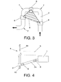
Figure 3 .- Shows a conventional schematic view of the zone of the duct exiting from the APU. -
Figure 4 .- Shows a schematic representation of a possible embodiment of the inventive structure. - Given below is a description of the invention based on the figures commented upon above.
- First of all, and in order to facilitate an understanding of the invention, a conventional structure of the pneumatic installation in the tail zone of an aircraft is described with the aid of
figures 1 to 3 , in order to complement and facilitate the understanding of the section on prior art of the invention. - As it was described in the prior art section of the present description, pneumatic facilities in the tail zone of an aircraft consist of an APU 1, the upper part of which has an air outlet to which is connected a
duct 2 which initially runs along the upper part of the aircraft, and which has to be located in the lowest part of the aircraft before reaching thepressurized passenger cabin 3. The situation occurs that close to the APU 1 is a strengtheningframe 4 for joining the section of the APU and the section of the HTP. The other frames 10 of the HTP are formed with a wider cross section in the upper part 10a than in the lower part 10b, in order to conveniently absorb the loading distribution generated on the vertical tail plane 10.. - Moreover, the
duct 2 has a considerable diameter, so there is little space for permitting theduct 2 to descend to the lower part of the aircraft, which means that in most cases in the state of the art theduct 2 runs along the upper part of the aircraft passing above thehorizontal stabilizer 5. To achieve this, some holes have to be made in theupper section 4a of theframe 4 so that theduct 2 can be allowed to pass. - This configuration leads to a great length of
duct 2 and the incorporation ofbends 4, which lead to a considerable loss of pressure, as it was mentioned before. - Moreover, the vibrations which the APU 1 transmits to the
duct 2 need to be compensated for, and this compensation is done by means ofcompensation elements 6 for the vibrations produced by the APU in its functioning and by means of theactual bends 7 required in the installation, which also carry out compensation of thermal expansions such that the angular movements produced by the APU are absorbed and theduct 2 is preserved from suffering fatigue and stresses affecting its working life. - The traditional way of tackling these compensations for the movements of the APU is by means of three
bends 7 as shown infigure 3 , which do not have to lie in the same plane, and by means of the incorporation of three compensatingelements 6, normally consisting of cardan joints. - The larger the
area 8 of the triangle formed by thecompensating elements 6 is, the greater the capacity to absorb movements in theduct 2 is. - The problem this solution involves, although simple and effective from the point of view of compensating for movements, is the amount of pressure losses that it introduces into the system since it is achieved by means of
bends 7 and extra length, precisely in the zone which is most sensitive to these losses. - In order to resolve these drawbacks, the present invention has developed a configuration of the pneumatic installation wherein the air compressed outlet of the APU 1 is arranged in the front part of the APU 1 and downwards the aircraft. Therefore it is necessary to redesign the APU 1, in such a way that the duct which is connected to it consist of a
straight pipe 2a inclined down towards the down part of the aircraft in such a way that it reaches theframe 4 via its lower part, which means that theduct 2 can pass through the lower part of the other frames 10, in other words on the upper edge of the lower section 10b of the frames 10, since the lower section 10b is much smaller than the upper section 10a, as was stated. Therefore, the new arrangement of the invention does not affect the structure of the aircraft and permits passage through the lower part of thetail plane 5 without having to incorporatebends 7. - Inserted in the
pipe 2a there arecompensation elements 6 for thermal expansion and for compensation of the vibrations in order to preserve thepipe 2a from breakages due to fatigue.
Claims (3)
- A CONFIGURATION OF THE PNEUMATIC INSTALLATION IN THE TAIL ZONE OF AN AIRCRAFT, which comprises an auxiliary power unit (1) (APU) for supply of pneumatic and electrical power, whose pneumatic power outlet is linked to a duct (2) which, before it reaches the zone of the pressurized passenger cabin (3), is located in the lower part of the aircraft, said duct (2) including bends (7) and compensation elements (6) for thermal expansion and for compensation of the vibrations produced by the auxiliary power unit (1) in its functioning, wherein the pneumatic outlet of the auxiliary power unit (1) is arranged in its front part in which is connected the duct consisting of a straight pipe (2a) inclined downwards toward the lower part of the aircraft in which two compensation elements (6) are inserted for thermal expansion and for compensation of the vibrations produced by the auxiliary power unit (1), in order to reduce the length of the duct (2) and eliminate the bends (7).
- A CONFIGURATION OF THE PNEUMATIC INSTALLATION IN THE TAIL ZONE OF AN AIRCRAFT, according to claim 1, wherein the pipe (2a) passes through a lower part of the horizontal stabilizer (5).
- A CONFIGURATION OF THE PNEUMATIC INSTALLATION IN THE TAIL ZONE OF AN AIRCRAFT, according to claim 1, wherein the pipe (2a) passes through the lower part of the opening conventionally presented by the strengthening frames (10) without affecting their structure.
Applications Claiming Priority (2)
| Application Number | Priority Date | Filing Date | Title |
|---|---|---|---|
| ES200801625A ES2358650B1 (en) | 2008-05-30 | 2008-05-30 | CONFIGURATION OF THE PNEUMATIC INSTALLATION IN THE COLA ZONE OF AN AIRCRAFT. |
| PCT/ES2009/070109 WO2009144345A1 (en) | 2008-05-30 | 2009-04-22 | Configuration of the pneumatic unit in the tail area of an aircraft |
Publications (2)
| Publication Number | Publication Date |
|---|---|
| EP2279946A1 true EP2279946A1 (en) | 2011-02-02 |
| EP2279946A4 EP2279946A4 (en) | 2013-08-21 |
Family
ID=41376627
Family Applications (1)
| Application Number | Title | Priority Date | Filing Date |
|---|---|---|---|
| EP09753999.3A Withdrawn EP2279946A4 (en) | 2008-05-30 | 2009-04-22 | Configuration of the pneumatic unit in the tail area of an aircraft |
Country Status (6)
| Country | Link |
|---|---|
| US (1) | US8128024B2 (en) |
| EP (1) | EP2279946A4 (en) |
| BR (1) | BRPI0910553B1 (en) |
| CA (1) | CA2720891C (en) |
| ES (1) | ES2358650B1 (en) |
| WO (1) | WO2009144345A1 (en) |
Families Citing this family (1)
| Publication number | Priority date | Publication date | Assignee | Title |
|---|---|---|---|---|
| FR2946955B1 (en) * | 2009-06-17 | 2012-09-21 | Airbus | AIRCRAFT COMPRISING A FUEL CELL SYSTEM. |
Family Cites Families (11)
| Publication number | Priority date | Publication date | Assignee | Title |
|---|---|---|---|---|
| RU1228409C (en) * | 1984-04-21 | 1995-06-27 | Авиационный комплекс им.С.В.Ильюшина | Auxiliary power plant for flying vehicle |
| US4706908A (en) * | 1984-10-10 | 1987-11-17 | Duncan Aviation, Inc. | Lightweight auxiliary power and forced air supply unit |
| RU1462678C (en) * | 1987-06-29 | 1995-01-20 | Авиационный комплекс им.С.В.Ильюшина | Auxiliary power-plant of aircraft |
| US5265408A (en) * | 1992-02-13 | 1993-11-30 | Allied-Signal Inc. | Exhaust eductor cooling system |
| DE19821952C2 (en) * | 1998-05-15 | 2000-07-27 | Dbb Fuel Cell Engines Gmbh | Power supply unit on board an aircraft |
| US6651929B2 (en) * | 2001-10-29 | 2003-11-25 | Pratt & Whitney Canada Corp. | Passive cooling system for auxiliary power unit installation |
| DE10301374B4 (en) * | 2003-01-16 | 2005-07-07 | Airbus Deutschland Gmbh | Bellows for the mechanical connection of two tubes arranged at a predetermined distance |
| US7975465B2 (en) * | 2003-10-27 | 2011-07-12 | United Technologies Corporation | Hybrid engine accessory power system |
| US7380749B2 (en) * | 2005-04-21 | 2008-06-03 | The Boeing Company | Combined fuel cell aircraft auxiliary power unit and environmental control system |
| US20080057848A1 (en) * | 2006-08-31 | 2008-03-06 | Honeywell International, Inc. | Venturi gate valve assembly for an auxiliary power unit |
| ES2316257B1 (en) * | 2006-10-31 | 2010-01-12 | Airbus España, S.L. | TAIL CONE FOR AIRCRAFT WITH MOBILE CARENA AND SUPPORT STRUCTURE OF AUXILIARY ENERGY UNIT AND ITS ANNEXED ELEMENTS. |
-
2008
- 2008-05-30 ES ES200801625A patent/ES2358650B1/en active Active
- 2008-09-23 US US12/232,731 patent/US8128024B2/en not_active Expired - Fee Related
-
2009
- 2009-04-22 WO PCT/ES2009/070109 patent/WO2009144345A1/en not_active Ceased
- 2009-04-22 BR BRPI0910553A patent/BRPI0910553B1/en active IP Right Grant
- 2009-04-22 EP EP09753999.3A patent/EP2279946A4/en not_active Withdrawn
- 2009-04-22 CA CA2720891A patent/CA2720891C/en active Active
Also Published As
| Publication number | Publication date |
|---|---|
| BRPI0910553B1 (en) | 2019-12-24 |
| US8128024B2 (en) | 2012-03-06 |
| CA2720891C (en) | 2016-07-05 |
| EP2279946A4 (en) | 2013-08-21 |
| WO2009144345A1 (en) | 2009-12-03 |
| CA2720891A1 (en) | 2009-12-03 |
| BRPI0910553A2 (en) | 2015-09-29 |
| US20090294581A1 (en) | 2009-12-03 |
| ES2358650B1 (en) | 2012-03-23 |
| ES2358650A1 (en) | 2011-05-12 |
Similar Documents
| Publication | Publication Date | Title |
|---|---|---|
| US10336458B2 (en) | Aircraft assembly comprising a mounting strut built into the nacelle and arranged at the rear section of the fuselage | |
| CN207244019U (en) | Sidepiece is provided with the crust breaking cylinder of bolt connecting hole | |
| CN102673791B (en) | Aircraft engine attachment pylon | |
| JP4704468B2 (en) | Aircraft engine assembly comprising an engine and an engine mounting structure for the engine | |
| EP2607658A2 (en) | Accessory mounting for a gas turbine | |
| US8132758B2 (en) | Environmental control system pack pallets | |
| CN101992808A (en) | Body structure of vehicle and assembling method therefor | |
| CN102849215B (en) | The rear streamlined trousers connecting pillar of aircraft engine | |
| US8128024B2 (en) | Structure of a pneumatic installation in a tail zone of an aircraft | |
| JP2016033005A (en) | Aircraft comprising a framework structure having at least one hollow frame | |
| CN201154710Y (en) | Brake integral module under vehicle | |
| CN103523033B (en) | A kind of elastic drivers' cab of locomotive | |
| CN100548805C (en) | Aircraft engine assembly | |
| CN102556332B (en) | The interchangeable connection scheme of aircraft rear fuselage tail cone | |
| CN102858635A (en) | Nacelle for an aircraft engine | |
| CN113564287A (en) | Ultra-low blast furnace equipment | |
| CN208646963U (en) | A kind of subframe and its vehicle | |
| CN115675096B (en) | High-speed pantograph drag reduction cladding chassis | |
| CN202648965U (en) | Dynamic stress testing apparatus assembly and motor train unit | |
| CN111470054A (en) | Aircraft flow device and aircraft comprising same | |
| CN109859928A (en) | A kind of transformer case and its manufacturing process | |
| CN110239898A (en) | A kind of bottom valve feed mechanism | |
| CN109094602A (en) | The drivers' cab Undercarriage structure and rail vehicle of energy-absorbing beam, rail vehicle | |
| CN107226192B (en) | Composite board and aircraft | |
| CN104960575B (en) | Auxiliary frame and engine beam installation bracket and manufacturing method thereof |
Legal Events
| Date | Code | Title | Description |
|---|---|---|---|
| PUAI | Public reference made under article 153(3) epc to a published international application that has entered the european phase |
Free format text: ORIGINAL CODE: 0009012 |
|
| 17P | Request for examination filed |
Effective date: 20101027 |
|
| AK | Designated contracting states |
Kind code of ref document: A1 Designated state(s): AT BE BG CH CY CZ DE DK EE ES FI FR GB GR HR HU IE IS IT LI LT LU LV MC MK MT NL NO PL PT RO SE SI SK TR |
|
| AX | Request for extension of the european patent |
Extension state: AL BA RS |
|
| RIN1 | Information on inventor provided before grant (corrected) |
Inventor name: CARVAJAL CORNEJO, JOSE Inventor name: ROJAS SANCHEZ, DAVID |
|
| DAX | Request for extension of the european patent (deleted) | ||
| A4 | Supplementary search report drawn up and despatched |
Effective date: 20130723 |
|
| RIC1 | Information provided on ipc code assigned before grant |
Ipc: B64D 41/00 20060101AFI20130717BHEP |
|
| 17Q | First examination report despatched |
Effective date: 20141121 |
|
| STAA | Information on the status of an ep patent application or granted ep patent |
Free format text: STATUS: THE APPLICATION IS DEEMED TO BE WITHDRAWN |
|
| 18D | Application deemed to be withdrawn |
Effective date: 20160406 |