EP2279945B1 - Launching system and launching apparatus - Google Patents
Launching system and launching apparatus Download PDFInfo
- Publication number
- EP2279945B1 EP2279945B1 EP09181040.8A EP09181040A EP2279945B1 EP 2279945 B1 EP2279945 B1 EP 2279945B1 EP 09181040 A EP09181040 A EP 09181040A EP 2279945 B1 EP2279945 B1 EP 2279945B1
- Authority
- EP
- European Patent Office
- Prior art keywords
- launching
- aircraft
- wing body
- rocket
- air
- Prior art date
- Legal status (The legal status is an assumption and is not a legal conclusion. Google has not performed a legal analysis and makes no representation as to the accuracy of the status listed.)
- Not-in-force
Links
Images


Classifications
-
- B—PERFORMING OPERATIONS; TRANSPORTING
- B64—AIRCRAFT; AVIATION; COSMONAUTICS
- B64D—EQUIPMENT FOR FITTING IN OR TO AIRCRAFT; FLIGHT SUITS; PARACHUTES; ARRANGEMENTS OR MOUNTING OF POWER PLANTS OR PROPULSION TRANSMISSIONS IN AIRCRAFT
- B64D1/00—Dropping, ejecting, releasing, or receiving articles, liquids, or the like, in flight
- B64D1/02—Dropping, ejecting, or releasing articles
- B64D1/04—Dropping, ejecting, or releasing articles the articles being explosive, e.g. bombs
-
- B—PERFORMING OPERATIONS; TRANSPORTING
- B64—AIRCRAFT; AVIATION; COSMONAUTICS
- B64D—EQUIPMENT FOR FITTING IN OR TO AIRCRAFT; FLIGHT SUITS; PARACHUTES; ARRANGEMENTS OR MOUNTING OF POWER PLANTS OR PROPULSION TRANSMISSIONS IN AIRCRAFT
- B64D3/00—Aircraft adaptations to facilitate towing or being towed
-
- B—PERFORMING OPERATIONS; TRANSPORTING
- B64—AIRCRAFT; AVIATION; COSMONAUTICS
- B64G—COSMONAUTICS; VEHICLES OR EQUIPMENT THEREFOR
- B64G1/00—Cosmonautic vehicles
- B64G1/002—Launch systems
- B64G1/005—Air launch
Definitions
- the present invention relates to a launching system for launching a flying object in air and a launching apparatus therefor.
- a method for launching a flying object in air
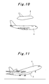
- a method for releasing a rocket 2 mounted on an upper surface of an aircraft 1 from the aircraft 1 as shown in Fig. 11
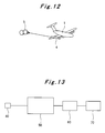
- a method for dropping and launching a rocket 3 attached on a lower surface of an aircraft 1 in air or as shown in Fig. 12 a method for pulling out a rocket 4 from a cargo space of an aircraft 1 with utilizing a parachute 5 and then launching the rocket 4 in air have been researched and developed.
- a rocket having additional wings 4 detachably mounted at a rear of steering wings 3 is disclosed in a Patent Literature No. 1.
- Another rocket having a detachable stable wing at a moment when moving power of the rocket is down is disclosed in a Patent Literature No. 2.
- these rockets are not suitable to a method for launching a rocket in air.
- US 2005/0116110 discloses a system for launching a missile from a launch region within the atmosphere of a planet, the missile being located within a flying vehicle before launching the missile.
- the system including a missile support coupled with the missile. The missile is launched after reaching the predetermined orientation.
- the preamble of claim 1 is based on this document.
- WO 98/10985 discloses an orbital launch system for launching orbital payloads.
- a turbofan powered aircraft with an aerospacecraft attached by an under wing pylon at an aircraft engine mount is used for carriage.
- the aerospacecraft has a cargo bay from which the payload is launched from the cargo bay.
- WO 89/08582 discloses rocket-powered, air-deployed, lift-assisted booster vehicle for carrying small payloads to orbital altitudes and velocities.
- the vehicle is secured beneath a conventional carrier aircraft and dropped therefrom at launch altitude and velocity.
- WO 96/15941 discloses an orbital launch vehicles with aerodynamic lifting surfaces enabling them to be towed as gliders behind conventional aircraft.
- the method of towing the launch vehicles uses a flexible cable to connect it with a conventional aircraft.
- US 7 458 544 discloses a system for launching a launch vehicle mounted beneath an aircraft.
- the present invention is developed so as to resolve the above drawback.
- a purpose of the present invention is to provide a launching system and a launching apparatus wherein a rocket can be launched in the air without designing a special mother ship for the rocket.
- a launching apparatus is characterized in that a flying object capable of being launched in air is detachably mounted on a wing body.
- a launching apparatus is characterized in that the wing body comprises wheel member for running.
- a launching apparatus is characterized in that the wing body comprises a main wing and a vertical wing.
- a launching apparatus is characterized in that the main wing is one of a delta wing and a joined-wing for generating elevation force.
- a launching apparatus is characterized in that the flying object comprises a head portion in which a small artificial satellite is installed.
- a launching apparatus is characterized in that the wing body has suspending means and the flying object is suspended by the suspending means, wherein the suspending means is detachable from the wing body.
- a launching apparatus as recited in claim 1 is provided.
- the launching system recited in claim 2 is characterized in that the launching apparatus is raised up to a launching height of the flying object by the aircraft towing the launching apparatus, and then the flying object is released from the wing body in the air and then the flying object is ignited and launched in the air.
- the launching system recited in claim 3 is characterized in that the flying object comprises a head portion in which a small artificial satellite is installed, and in that the small artificial satellite is released after the flying object is launched in the air.
- the launching system recited in claim 4 is characterized in that the wing body comprises a sensor for locking the aircraft, wherein the sensor is installed in the wing body; and a homing device for automatically controlling a control surface of the wing body so as to maintain the wing body at a proper position with respect to the aircraft in accordance with data obtained by the sensor.
- the launching system recited in claim 5 is characterized in that the wing body installs a sensor for locking the aircraft for towing and the aircraft comprises a homing device for automatically controlling the control surface so as to maintain the wing body at a proper position with respect to the aircraft in accordance with data obtained by the sensor, wherein the wing body is remote controlled by a line control method with the cable or a radio control method.
- the launching system recited in claim 6 is characterized in that the wing body released from the flying object is glided in the air and returned to the nearest airport after cutting the cable connected to the aircraft.
- the launching system as recited in claim 7 is characterized in that a winding device for winding up the cable is provided at one of the aircraft and the launching apparatus wherein an interval distance between the aircraft and the launching apparatus is adjusted by winding up/unwinding from the cable.
- a launching system not forming part of the presently claimed invention is characterized in that it comprises a launching apparatus and an aircraft, wherein the launching apparatus is mounted on an upper surface or a lower surface of the aircraft and the aircraft is taken off and then the launching apparatus is released from the aircraft after raising up the launching apparatus to a launching height of the flying object by the aircraft and then the flying object is ignited and launched in air after releasing the flying object from the wing body.
- a launching system not forming part of the presently claimed invention is characterized in that it comprises a launching apparatus and an aircraft, wherein the launching apparatus is installed in a cargo space of the aircraft and the aircraft is taken off and then the launching apparatus is pulled out from the cargo space of the aircraft after raising up the launching apparatus to a launching height of the flying object by the aircraft and then the flying object is ignited and launched in air after releasing the flying object from the wing body.
- a rocket capable of being launched in air is detachably mounted on a wing body so that the rocket is detached from the wing body after raising the launching apparatus to a launching level of the rocket and then the rocket is ignited and launched in air.
- a wing body comprises wheels so as to run so that the wing body can be glided on a runway while the wing body is towed by the aircraft.
- a wing body has a main wing and a vertical tail assembly so that the wing body can be glided on a runway and taken off while the wing body is towed by the aircraft. Then, the wing body can be raised up to a launching height of a rocket.
- a main wing of a wing body is one of a delta wing and a joined-wing for generating elevation force so that the wing body can be easily taken off while the wing body is towed by the aircraft.
- a small artificial satellite is installed in a head portion of the rocket so that the small artificial satellite is released from the rocket after the rocket reaches its orbit.
- a rocket is suspended from a wing body in air by a suspending member detachable from the wing body so that the rocket can be easily separated from the wing body by cutting the suspending member.
- a rocket is suspended from the wing body with two lanyards capable of being cut in air.
- the rocket can easily approach its orbit in a short time immediately after launching the rocket in air since the head portion of the rocket is already arranged toward an upward direction before igniting the rocket by cutting one lanyard at first and then cutting another lanyard so as to separate the rocket from the wing body.
- a wing body of a launching apparatus comprises wheels for running and is towed by an aircraft so as to be run and taken off. By cutting the cable, the launching apparatus can be easily released from a mother ship after the launching apparatus is taken off.
- a launching apparatus towed by an aircraft is raised up to a launching level of a rocket and then the rocket is separated from a wing body in the air. Then, the rocket is ignited and launched in the air.
- a research cost and an operation cost can be remarkably reduced.
- a wing body installs a sensor for locking an aircraft for towing.
- the wing body comprises a homing device for automatically controlling a control surface of the wing body so as to maintain a proper position of the wing body with respect to the aircraft in accordance with data obtained by the sensor so that the wing body can be an unmanned aerial vehicle (UAV).
- UAV unmanned aerial vehicle
- a wing body installs a sensor for locking on the aircraft for towing and a homing device for automatically controlling a control surface of the wing body so as to maintain a proper position of the wing body with respect to the aircraft in accordance with data obtained by the sensor.
- the wing body can be remote-controlled by a line control method with the cable or a radio control method so that a position of the wing body is automatically maintained with respect to an aircraft and the wing body can be an unmanned aerial vehicle. Further, a weight of the wing body becomes light since the wing body does not comprise a homing device therein.
- a wing body released from a rocket is separated from an aircraft by cutting a cable and returned to the nearest airport by flying in the air so that the operation cost of the launching apparatus can be remarkably reduced.
- an aircraft of a launching apparatus comprises a winding device for winding up a cable so that an interval distance between the aircraft and the launching apparatus can be adjusted by winging up or unwinding from the winding device.
- a rocket capable for being launched in air is detachably attached to a wing body of a launching apparatus and the launching apparatus is mounted on an upper surface or a lower surface of an aircraft. Then, the aircraft is raised up to a launching level of the launching apparatus and then the launching apparatus is separated from the aircraft and the wing body is separated from the rocket.
- the rocket is ignited and launched in air, a research cost and an operation cost can be remarkably reduced except a cost for developing a suitable aircraft.
- a rocket capable of being launched in air is detachably attached to a wing body of a launching apparatus and the launching apparatus is installed in a cargo space in an aircraft.
- the aircraft is raised up to a launching level of the launching apparatus and then the launching apparatus is pulled out from the aircraft and the rocket is separated from the wing body.
- the rocket is ignited and launched in air.
- a launching system of the first example according to the present invention is shown in Fig. 1 to Fig. 8 .
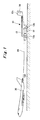
- the launching system of the example as shown in Fig. 1 to Fig. 8 comprises a launching apparatus 10 towed by an aircraft 30 through a cable 20 so as to take off the launching apparatus 10 from a runway 100 in a method for towing the launching apparatus 10, wherein a rocket 11 is detached from a wing body 12 of the launching apparatus 10 and the rocket 11 can be launched in air.
- a rocket is sufficiently small and the rocket can install a small artificial satellite in its head portion and the small artificial satellite can be released from the small rocket and put the small artificial satellite on a low-degree orbit, that is, a height of 300km to 800km from the earth. It is unnecessary for the rocket 11 to be provided with anything other than a wing body 12.
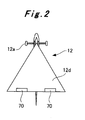
- the wing body 12 comprises wheel members 12a and 12b wherein the wheel members 12a and 12b are provided at a front portion and a rear portion of the wing body 12, respectively so as to be glided on the runway 100.
- the wing body 12 comprises a vertical tail assembly 12c at a rear portion of the wing body 12.
- a delta wing 12d is provided as a main wing so as to generate elevation force.
- the delta wing 12d is a flat-shaped wing.
- a front edge of the delta wing has a swept-back angle and a rear edge of the delta wing is arranged perpendicular to a longitudinal axis of the aircraft.
- the delta wing 12d looks like a triangle shape.
- the delta wing 12d generates elevation force and the launching apparatus 10 is towed by the aircraft 30 so that the launching apparatus 10 can be easily taken off.
- the wing body 12 may install an auxiliary driving device so as to assist its flight when the wing body 12 is glided.
- the wing body 12 is an "Unmanned Aerial Vehicle (UAV)" and comprises a control system as shown in Fig. 13 so as to home in on the aircraft 30 that tows the wing body 12.
- UAV Unmanned Aerial Vehicle
- a sensor 40 for homing in on the aircraft 30 that tows the wing body 12 and a homing device 50 for controlling a control surface of the aircraft 30 so as to maintain a desired position of the wing body 12 (e.g. in a constant style) with respect to the aircraft 30.
- the sensor 40 locks the aircraft 30 while the launching apparatus is towed by the aircraft 30 in air.
- the homing device 50 controls the control surface of the wing body 12 by adjusting a part of a wing body (flap) in order to maintain the aircraft 30 locked by the sensor 40 at a constant style with respect to the wind body 12.
- an actuator 60 controls the flap 70 of the vertical tail wing 12c or the delta wing 12d.
- the homing device 50 may not be installed in a wing body and may be installed in an aircraft 30 by utilizing a line control method with a cable or a radio control method so as to control the control surface of the wing body 12 from a remote location.
- a redundant device such as a homing device 50 is unnecessary in the wing body 12 and the position of the wing body 12 can be stably maintained as desired (e.g. in a constant style) with respect to the aircraft 30.
- a winding device (not shown) for winding a cable 20 may be provided at an aircraft or a launching apparatus 10.
- the winding device winds up the cable 20 and unwinds the cable 20 up, so that an interval distance between the aircraft 30 and the launching apparatus 10 can be adjusted.
- the distance between the aircraft 30 and the launching apparatus 10 becomes suitable so that a position of the wing body 12 can be set in a preferable style with respect to the aircraft 30.
- wing body 12 as shown in Fig. 1 through Fig. 8 is drawn in exaggerated proportions, that is, the wing body 12 is drawn larger than a real one, the wing body 12 is actually much smaller than the aircraft 30.
- a total length of the wing body is about 10m and the total width thereof is about 8m.
- the launching apparatus 10 is towed by the aircraft 30 with the cable 20 and taken off.
- the rocket 11 is released from the wind body 12 and then the rocket 11 can be ignited in air.
- the launching apparatus 10 is towed by the aircraft 30 with the cable 20 and run on a runway 100 so as to be taken off. Then, the rocket 11 can be raised to a launching level. As shown in a dotted-line in Fig. 5 , the wing body 12 homes in on the aircraft 30 for towing the wing body 12 by the sensor 40. In accordance with data obtained by the sensor, the surface control of the wing body 12 can be automatically adjusted with respect to the aircraft.
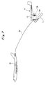
- a rocket 11 is suspended by the wing body 12 with two lanyards 13a and 13b, wherein the lanyards can be cut off and one lanyard 13a is arranged at a front portion and another lanyard 13b is arranged at a rear portion of the wing body 12.
- the lanyards 13a and 13b are merely one of examples for suspending the rocket 11. It is also possible to utilize a wire, a chain or a suspending rope and so on. The number of lanyards is not restricted to two.
- the rear lanyard 13b is cut off and the rocket is suspended with the front lanyard 13a.
- a head portion of the rocket 11 is arranged in an upward direction.
- the rocket 11 is separated from the wing body 12 and the rocket 11 is ignited in air so as to be launched toward a front-inclined direction.
- the rocket 11 is suspended by the two lanyards 13a and 13b.
- the rocket 11 can be easily separated from the wing body 12 by cutting off the front lanyard 13a and the rear lanyard 13b.
- the rocket 11 is launched in air while the head portion of the rocket 11 is arranged toward an upward direction. It is an advantage that the rocket 11 can be raised up immediately after launching and the rocket 11 can reach its orbit in a short time.
- the rocket 11 is suspended by two lanyards 13a and 13b.
- any number of lanyards is acceptable.
- the head portion of the rocket is arranged toward a front direction.
- the front lanyard may be cut off after the rear lanyard is cut off at first so as to launch the rocket toward a front inclined direction.
- the other arrangement is acceptable.
- the rear lanyard 13b is cut off after the front lanyard 13a is cut off at first so as to launch the rocket 11 toward rear inclined direction.
- the rocket is launched in air toward a direction opposite to a flying direction of the aircraft 30.
- the rocket can be more safely launched.
- the wing body 12 and the aircraft 30 are connected with the cable 20 as shown in Fig. 8 at a moment when the rocket 11 is ignited in air
- the other cases are acceptable in the present invention.
- the cable connecting the wing body 12 and the aircraft 20 may be cut and the aircraft 30 is escaped to a safety air zone, so that the launching operation becomes safer.
- the launching apparatus 10 is towed and taken off by the aircraft 30 with a cable.
- the launching apparatus 10 is raised to a launch level and then the rocket 11 is ignited and launched in air by releasing the rocket 11 from the wing body 12.
- the wing body 12 of the present example makes a special mother ship unnecessary. Thereby, a launching system for launching a rocket in air can be developed with a remarkably low cost.
- the small artificial satellite can be discharged after the rocket 11 has reached its orbit. Thereby, it is possible to develop an artificial satellite smoothly and quickly applicable to security matters and disaster observation.
- Fig. 9 shows the second example according to the present invention.
- the second example utilizes a joined-wing 80 for generating elevation force instead of a delta wing 12d as a main wing of the wing body 12 of the first example.
- the joined-wing 80 has a structure that a vertical tail assembly with a sweptforward angle is joined to a main wing 81 with a sweptback angle.
- the joined-wing 80 can generate elevation force equal or larger than that generated by the delta wing 12d of the first example.
- a rocket 11 can be separated from a wing body 12 with the joined-wing 80 as a main wing so that the effect and the advantage of the second example are as same as those of the first example.
- the examples 1 and 2 as described above employ a tow method for towing a launching apparatus 10 by an aircraft 30.
- the third example does not employ the tow method and employs an improved method by improving a conventional air launching method as described in the Background Art.
- the third example can be largely divided into two methods.
- a method is as follows:
- the other method is as follows:
- a launching apparatus is not towed by an aircraft.
- a rocket is mounted on an aircraft or installed in a cargo space of an aircraft and then the aircraft is taken off.
- a present method for launching a rocket in air can be launched at a remarkably low cost.
- the cost of developing a system for launching a rocket in air can be remarkably reduced.
- a rocket in which a small artificial satellite is installed can be launched systematically at a low cost. It is possible to develop an artificial satellite smoothly and quickly applicable to security matters and disaster observation and so on. Therefore, the present invention can be utilized in various industrial fields.
Description
- The present invention relates to a launching system for launching a flying object in air and a launching apparatus therefor.
- As a method for launching a flying object (hereinafter called as "rocket") in air, as shown in
Fig. 10 , a method for releasing arocket 2 mounted on an upper surface of anaircraft 1 from theaircraft 1, as shown inFig. 11 , a method for dropping and launching arocket 3 attached on a lower surface of anaircraft 1 in air or as shown inFig. 12 , a method for pulling out arocket 4 from a cargo space of anaircraft 1 with utilizing aparachute 5 and then launching therocket 4 in air have been researched and developed. - As a rocket, a rocket having
additional wings 4 detachably mounted at a rear ofsteering wings 3 is disclosed in a Patent Literature No. 1. Another rocket having a detachable stable wing at a moment when moving power of the rocket is down is disclosed in a Patent Literature No. 2. However, these rockets are not suitable to a method for launching a rocket in air. -
US 2005/0116110 discloses a system for launching a missile from a launch region within the atmosphere of a planet, the missile being located within a flying vehicle before launching the missile. The system including a missile support coupled with the missile. The missile is launched after reaching the predetermined orientation. The preamble ofclaim 1 is based on this document. -
WO 98/10985 -
WO 89/08582 -
WO 96/15941 -
US 7 458 544 discloses a system for launching a launch vehicle mounted beneath an aircraft. -
- {Patent Literature No.1}
Japanese Patent Unexamined Publication No.5-079798 - {Patent Literature No.2}
Japanese Patent Unexamined Publication No.5-231800 - In order to develop new other methods for launching a rocket in air, it is necessary to develop an
aircraft 1 as a mother ship androckets - However, the methods described above have a drawback, that is, those techniques could not apply to a development of a satellite type flying object suitable for quickly observing disaster temporally happened.
- The present invention is developed so as to resolve the above drawback. A purpose of the present invention is to provide a launching system and a launching apparatus wherein a rocket can be launched in the air without designing a special mother ship for the rocket.
- In a launching apparatus not forming part of the presently claimed invention, a launching apparatus is characterized in that a flying object capable of being launched in air is detachably mounted on a wing body.
- In a launching apparatus not forming part of the presently claimed invention, a launching apparatus is characterized in that the wing body comprises wheel member for running.
- In a launching apparatus not forming part of the presently claimed invention, a launching apparatus is characterized in that the wing body comprises a main wing and a vertical wing.
- In a launching apparatus not forming part of the presently claimed invention, a launching apparatus is characterized in that the main wing is one of a delta wing and a joined-wing for generating elevation force.
- In a launching apparatus not forming part of the presently claimed invention, a launching apparatus is characterized in that the flying object comprises a head portion in which a small artificial satellite is installed.
- In a launching apparatus not forming part of the presently claimed invention, a launching apparatus is characterized in that the wing body has suspending means and the flying object is suspended by the suspending means, wherein the suspending means is detachable from the wing body.
- To accomplish the above purpose in a launching apparatus, a launching apparatus as recited in
claim 1 is provided. - To accomplish the above purpose in a launching system as claimed in
claim 1, the launching system recited inclaim 2 is characterized in that the launching apparatus is raised up to a launching height of the flying object by the aircraft towing the launching apparatus, and then the flying object is released from the wing body in the air and then the flying object is ignited and launched in the air. - To accomplish the above purpose in a launching system as claimed in
claim 2, the launching system recited inclaim 3 is characterized in that the flying object comprises a head portion in which a small artificial satellite is installed, and in that the small artificial satellite is released after the flying object is launched in the air. - To accomplish the above purpose in a launching system as claimed in
claim 1, the launching system recited inclaim 4 is characterized in that the wing body comprises a sensor for locking the aircraft, wherein the sensor is installed in the wing body; and a homing device for automatically controlling a control surface of the wing body so as to maintain the wing body at a proper position with respect to the aircraft in accordance with data obtained by the sensor. - To accomplish the above purpose in a launching system as claimed in
claim 1, the launching system recited inclaim 5 is characterized in that the wing body installs a sensor for locking the aircraft for towing and the aircraft comprises a homing device for automatically controlling the control surface so as to maintain the wing body at a proper position with respect to the aircraft in accordance with data obtained by the sensor, wherein the wing body is remote controlled by a line control method with the cable or a radio control method. - To accomplish the above purpose in a launching system as claimed in
claim 1, the launching system recited in claim 6 is characterized in that the wing body released from the flying object is glided in the air and returned to the nearest airport after cutting the cable connected to the aircraft. - To accomplish the above purpose in a launching system as claimed in
claim 1, the launching system as recited inclaim 7 is characterized in that a winding device for winding up the cable is provided at one of the aircraft and the launching apparatus wherein an interval distance between the aircraft and the launching apparatus is adjusted by winding up/unwinding from the cable. - A launching system not forming part of the presently claimed invention is characterized in that it comprises a launching apparatus and an aircraft, wherein the launching apparatus is mounted on an upper surface or a lower surface of the aircraft and the aircraft is taken off and then the launching apparatus is released from the aircraft after raising up the launching apparatus to a launching height of the flying object by the aircraft and then the flying object is ignited and launched in air after releasing the flying object from the wing body.
- A launching system not forming part of the presently claimed invention is characterized in that it comprises a launching apparatus and an aircraft, wherein the launching apparatus is installed in a cargo space of the aircraft and the aircraft is taken off and then the launching apparatus is pulled out from the cargo space of the aircraft after raising up the launching apparatus to a launching height of the flying object by the aircraft and then the flying object is ignited and launched in air after releasing the flying object from the wing body.
- In the launching apparatus not forming part of the presently claimed invention, a rocket capable of being launched in air is detachably mounted on a wing body so that the rocket is detached from the wing body after raising the launching apparatus to a launching level of the rocket and then the rocket is ignited and launched in air.
- In the launching apparatus not forming part of the presently claimed invention, a wing body comprises wheels so as to run so that the wing body can be glided on a runway while the wing body is towed by the aircraft.
- In the launching apparatus not forming part of the presently claimed invention, a wing body has a main wing and a vertical tail assembly so that the wing body can be glided on a runway and taken off while the wing body is towed by the aircraft. Then, the wing body can be raised up to a launching height of a rocket.
- In the launching apparatus not forming part of the presently claimed invention, a main wing of a wing body is one of a delta wing and a joined-wing for generating elevation force so that the wing body can be easily taken off while the wing body is towed by the aircraft.
- In the launching apparatus not forming part of the presently claimed invention, a small artificial satellite is installed in a head portion of the rocket so that the small artificial satellite is released from the rocket after the rocket reaches its orbit. Thus, it is possible to develop an artificial satellite smoothly and quickly applicable to security matter and disaster observation.
- In the launching apparatus not forming part of the presently claimed invention, a rocket is suspended from a wing body in air by a suspending member detachable from the wing body so that the rocket can be easily separated from the wing body by cutting the suspending member.
- In the launching apparatus not forming part of the presently claimed invention, a rocket is suspended from the wing body with two lanyards capable of being cut in air. The rocket can easily approach its orbit in a short time immediately after launching the rocket in air since the head portion of the rocket is already arranged toward an upward direction before igniting the rocket by cutting one lanyard at first and then cutting another lanyard so as to separate the rocket from the wing body.
- In the launching system as recited in
claim 1, a wing body of a launching apparatus comprises wheels for running and is towed by an aircraft so as to be run and taken off. By cutting the cable, the launching apparatus can be easily released from a mother ship after the launching apparatus is taken off. - In the launching system as recited in
claim 2, a launching apparatus towed by an aircraft is raised up to a launching level of a rocket and then the rocket is separated from a wing body in the air. Then, the rocket is ignited and launched in the air. Thus, it is unnecessary to develop an aircraft as a mother ship. A research cost and an operation cost can be remarkably reduced. - In the launching system as recited in
claim 3, after a rocket launched in air reaches its orbit, a small artificial satellite installed in a head portion of the rocket is released so that the satellite can be smoothly and quickly applicable to security matter and disaster observation. - In a launching system as recited in
claim 4, a wing body installs a sensor for locking an aircraft for towing. The wing body comprises a homing device for automatically controlling a control surface of the wing body so as to maintain a proper position of the wing body with respect to the aircraft in accordance with data obtained by the sensor so that the wing body can be an unmanned aerial vehicle (UAV). - In a launching system as recited in
claim 5, a wing body installs a sensor for locking on the aircraft for towing and a homing device for automatically controlling a control surface of the wing body so as to maintain a proper position of the wing body with respect to the aircraft in accordance with data obtained by the sensor. The wing body can be remote-controlled by a line control method with the cable or a radio control method so that a position of the wing body is automatically maintained with respect to an aircraft and the wing body can be an unmanned aerial vehicle. Further, a weight of the wing body becomes light since the wing body does not comprise a homing device therein. - In a launching system as claimed in claim 6, a wing body released from a rocket is separated from an aircraft by cutting a cable and returned to the nearest airport by flying in the air so that the operation cost of the launching apparatus can be remarkably reduced.
- In a launching system as recited in
claim 7, an aircraft of a launching apparatus comprises a winding device for winding up a cable so that an interval distance between the aircraft and the launching apparatus can be adjusted by winging up or unwinding from the winding device. Thus, it is an advantage that a position of a wing body is maintained at a proper position by adjusting the interval distance between the launching apparatus and the aircraft. - In a launching system not forming part of the presently claimed invention, a rocket capable for being launched in air is detachably attached to a wing body of a launching apparatus and the launching apparatus is mounted on an upper surface or a lower surface of an aircraft. Then, the aircraft is raised up to a launching level of the launching apparatus and then the launching apparatus is separated from the aircraft and the wing body is separated from the rocket. The rocket is ignited and launched in air, a research cost and an operation cost can be remarkably reduced except a cost for developing a suitable aircraft.
- In a launching system not forming part of the presently claimed invention, a rocket capable of being launched in air is detachably attached to a wing body of a launching apparatus and the launching apparatus is installed in a cargo space in an aircraft. The aircraft is raised up to a launching level of the launching apparatus and then the launching apparatus is pulled out from the aircraft and the rocket is separated from the wing body. The rocket is ignited and launched in air. Thus, a research cost and an operation cost of the launching system can be remarkably reduced except a cost developing for a suitable aircraft.
-
- {
Fig. 1} Fig.1 shows a launching system of the first example according to the present invention wherein a launching apparatus is towed and glided by an aircraft. - {
Fig. 2} Fig. 2 shows a top view of the launching apparatus in the launching system of the first example according to the present invention. - {
Fig. 3} Fig. 3 shows that a launching apparatus in the launching system of the first example according to the present invention, wherein the launching apparatus is towed by an aircraft and glided at a moment immediately before the launching apparatus is taken off. - {
Fig. 4} Fig. 4 shows that a launching apparatus in the launching system of the first example according to the present invention is towed by an aircraft in air. - {
Fig. 5} Fig. 5 shows that a launching apparatus in the launching system of the first example according to the present invention homes in on an aircraft by a sensor. - {
Fig. 6} Fig. 6 shows that a launching apparatus in the launching system of the first example according to the present invention suspends a rocket with lanyards. - {
Fig. 7} Fig. 7 shows that a launching apparatus in the launching system of the first example according to the present invention has two lanyards and a rocket is just suspended with one of the lanyards so as to arrange a head portion of the rocket directed toward an upward direction. - {
Fig. 8} Fig. 8 shows that a launching apparatus in the launching system of the first example according to the present invention cuts one lanyard and a rocket is ignited and launched in air. - {
Fig. 9} Figs. 9(a), 9(b) and 9(c) show a launching apparatus in a launching system of the second example according to the present invention.Fig. 9(a) shows its top view.Fig. 9(b) shows its front view.Fig. 9(c) shows it side view. - {
Fig. 10} Fig. 10 shows a method for launching a rocket in air wherein the rocket is mounted on an upper surface of an aircraft. - {
Fig. 11} Fig. 11 shows a method for launching a rocket in air wherein the rocket is mounted on a lower surface of an aircraft. - {
Fig. 12} Fig. 12 shows a method for launching a rocket in air wherein the rocket is installed in a cargo space of an aircraft. - {
Fig. 13} Fig. 13 shows a block diagram of a control system installed in a wing body in the first example according to the present invention. - Concerning the best mode to do the present invention, it will be described with reference to the following description.
- A launching system of the first example according to the present invention is shown in
Fig. 1 to Fig. 8 . - The launching system of the example as shown in
Fig. 1 to Fig. 8 comprises a launchingapparatus 10 towed by anaircraft 30 through acable 20 so as to take off the launchingapparatus 10 from arunway 100 in a method for towing thelaunching apparatus 10, wherein arocket 11 is detached from awing body 12 of the launchingapparatus 10 and therocket 11 can be launched in air. - For instance, a rocket is sufficiently small and the rocket can install a small artificial satellite in its head portion and the small artificial satellite can be released from the small rocket and put the small artificial satellite on a low-degree orbit, that is, a height of 300km to 800km from the earth. It is unnecessary for the
rocket 11 to be provided with anything other than awing body 12. - As shown in
Fig. 1 andFig. 2 , thewing body 12 compriseswheel members wheel members wing body 12, respectively so as to be glided on therunway 100. Thewing body 12 comprises avertical tail assembly 12c at a rear portion of thewing body 12. Further, as shown inFig. 2 , adelta wing 12d is provided as a main wing so as to generate elevation force. Thedelta wing 12d is a flat-shaped wing. A front edge of the delta wing has a swept-back angle and a rear edge of the delta wing is arranged perpendicular to a longitudinal axis of the aircraft. In a view of a point above the delta wing, thedelta wing 12d looks like a triangle shape. Thedelta wing 12d generates elevation force and the launchingapparatus 10 is towed by theaircraft 30 so that the launchingapparatus 10 can be easily taken off. - Although the
wing body 12 does not employ any driving device for taking off by itself, thewing body 12 may install an auxiliary driving device so as to assist its flight when thewing body 12 is glided. - The
wing body 12 is an "Unmanned Aerial Vehicle (UAV)" and comprises a control system as shown inFig. 13 so as to home in on theaircraft 30 that tows thewing body 12. - In the
wing body 12 as shown inFig. 13 , there are asensor 40 for homing in on theaircraft 30 that tows thewing body 12 and a homingdevice 50 for controlling a control surface of theaircraft 30 so as to maintain a desired position of the wing body 12 (e.g. in a constant style) with respect to theaircraft 30. - As shown in a dotted-line in
Fig. 5 , thesensor 40 locks theaircraft 30 while the launching apparatus is towed by theaircraft 30 in air. - The homing
device 50 controls the control surface of thewing body 12 by adjusting a part of a wing body (flap) in order to maintain theaircraft 30 locked by thesensor 40 at a constant style with respect to thewind body 12. In practical terms, as shown inFig. 13 , anactuator 60 controls theflap 70 of thevertical tail wing 12c or thedelta wing 12d. - Alternatively, the homing
device 50 may not be installed in a wing body and may be installed in anaircraft 30 by utilizing a line control method with a cable or a radio control method so as to control the control surface of thewing body 12 from a remote location. In the above case, a redundant device such as a homingdevice 50 is unnecessary in thewing body 12 and the position of thewing body 12 can be stably maintained as desired (e.g. in a constant style) with respect to theaircraft 30. - Further, a winding device (not shown) for winding a
cable 20 may be provided at an aircraft or alaunching apparatus 10. The winding device winds up thecable 20 and unwinds thecable 20 up, so that an interval distance between theaircraft 30 and the launchingapparatus 10 can be adjusted. By utilizing the adjustment, the distance between theaircraft 30 and the launchingapparatus 10 becomes suitable so that a position of thewing body 12 can be set in a preferable style with respect to theaircraft 30. - Although the
wing body 12 as shown inFig. 1 through Fig. 8 is drawn in exaggerated proportions, that is, thewing body 12 is drawn larger than a real one, thewing body 12 is actually much smaller than theaircraft 30. For instance, a total length of the wing body is about 10m and the total width thereof is about 8m. - If an
aircraft 30 tows the launchingapparatus 10 and then the launchingapparatus 10 is taken off, it is unnecessary to develop a special aircraft. - For example, it is possible to utilize a passenger plane, a cargo plane, a transport plane and so on.
- By utilizing the launching system of the first example described above, the launching
apparatus 10 is towed by theaircraft 30 with thecable 20 and taken off. When the launchingapparatus 10 is raised to a launching level, therocket 11 is released from thewind body 12 and then therocket 11 can be ignited in air. - That is, as shown in
Fig. 3 , the launchingapparatus 10 is towed by theaircraft 30 with thecable 20 and run on arunway 100 so as to be taken off. Then, therocket 11 can be raised to a launching level. As shown in a dotted-line inFig. 5 , thewing body 12 homes in on theaircraft 30 for towing thewing body 12 by thesensor 40. In accordance with data obtained by the sensor, the surface control of thewing body 12 can be automatically adjusted with respect to the aircraft. - As shown in
Fig. 6 , arocket 11 is suspended by thewing body 12 with twolanyards lanyard 13a is arranged at a front portion and anotherlanyard 13b is arranged at a rear portion of thewing body 12. Thelanyards rocket 11. It is also possible to utilize a wire, a chain or a suspending rope and so on. The number of lanyards is not restricted to two. - As shown in
Fig.7 , therear lanyard 13b is cut off and the rocket is suspended with thefront lanyard 13a. A head portion of therocket 11 is arranged in an upward direction. And then, as shown inFig. 8 , by cutting off thefront lanyard 13a, therocket 11 is separated from thewing body 12 and therocket 11 is ignited in air so as to be launched toward a front-inclined direction. - In the present example, the
rocket 11 is suspended by the twolanyards rocket 11 can be easily separated from thewing body 12 by cutting off thefront lanyard 13a and therear lanyard 13b. - The
rocket 11 is launched in air while the head portion of therocket 11 is arranged toward an upward direction. It is an advantage that therocket 11 can be raised up immediately after launching and therocket 11 can reach its orbit in a short time. - In the above example, the
rocket 11 is suspended by twolanyards - For instance, in the case that a head portion of a
rocket 11 is arranged toward a rear direction, therear lanyard 13b is cut off after thefront lanyard 13a is cut off at first so as to launch therocket 11 toward rear inclined direction. - In the case, the rocket is launched in air toward a direction opposite to a flying direction of the
aircraft 30. Thus, the rocket can be more safely launched. - It is the easiest way that a
cable 20 connecting awing body 12 from which therocket 11 has been already separated and theaircraft 30 is cut and thewing body 12 is discarded after launching the rocket in the air. However, if thewing body 12 from which therocket 11 has been already separated is still towed by theaircraft 30 and landed at the nearest airport, the operation cost of a launching apparatus can be remarkably reduced. - If a
cable 20 connecting anaircraft 30 and awing body 12 is cut and thewing body 12 can glide in air and be navigated so as to land at the nearest airport, the operation cost of a launching apparatus can be remarkably reduced similarly to the above. - Further, although the
wing body 12 and theaircraft 30 are connected with thecable 20 as shown inFig. 8 at a moment when therocket 11 is ignited in air, the other cases are acceptable in the present invention. For instance, before therocket 11 is ignited and launched in the air, the cable connecting thewing body 12 and theaircraft 20 may be cut and theaircraft 30 is escaped to a safety air zone, so that the launching operation becomes safer. - As described above, in accordance with the launching system of the present example, the launching
apparatus 10 is towed and taken off by theaircraft 30 with a cable. The launchingapparatus 10 is raised to a launch level and then therocket 11 is ignited and launched in air by releasing therocket 11 from thewing body 12. Thus, thewing body 12 of the present example makes a special mother ship unnecessary. Thereby, a launching system for launching a rocket in air can be developed with a remarkably low cost. On the other hand, it is unnecessary to develop anaircraft 30 as a mother ship so that a development cost and an operation cost can be remarkably reduced. - Particularly, if a
rocket 11 installs a small artificial satellite at a head portion, the small artificial satellite can be discharged after therocket 11 has reached its orbit. Thereby, it is possible to develop an artificial satellite smoothly and quickly applicable to security matters and disaster observation. -
Fig. 9 shows the second example according to the present invention. - The second example utilizes a joined-
wing 80 for generating elevation force instead of adelta wing 12d as a main wing of thewing body 12 of the first example. - As shown in
Fig. 9 , the joined-wing 80 has a structure that a vertical tail assembly with a sweptforward angle is joined to amain wing 81 with a sweptback angle. The joined-wing 80 can generate elevation force equal or larger than that generated by thedelta wing 12d of the first example. - In the second example, a
rocket 11 can be separated from awing body 12 with the joined-wing 80 as a main wing so that the effect and the advantage of the second example are as same as those of the first example. - The examples 1 and 2 as described above employ a tow method for towing a
launching apparatus 10 by anaircraft 30. The third example does not employ the tow method and employs an improved method by improving a conventional air launching method as described in the Background Art. The third example can be largely divided into two methods. - A method is as follows:
- (1) A launching apparatus is taken off with an aircraft wherein the launching apparatus is mounted on an upper surface or a lower surface of the aircraft. As described in the first example, a rocket capable for launching in air is detachably attached to a wing body.
- (2)The launching system is raised to a launching level by the aircraft.
- (3)Like the first example, the rocket is separated from the wing body and then the rocked is ignited and launched in the air.
- The other method is as follows:
- (1) An aircraft is taken off wherein a launching apparatus is installed in a cargo space of the aircraft. As described in the first example, a rocket capable for igniting in air is detachably attached to a wing body.
- (2)The launching system is raised to a launching level for launching the rocket by the aircraft.
- (3)The launching system is pulled out from the cargo space of the aircraft.
- (4)After that, like the first example as described above, the rocket is released from the wing body and the rocket is ignited and launched in air.
- According to the third example, a launching apparatus is not towed by an aircraft. A rocket is mounted on an aircraft or installed in a cargo space of an aircraft and then the aircraft is taken off. Upon comparing with the tow method in the first and second examples and the present methods of the third example, there is an advantage that a necessary length of a runway on which the aircraft takes off can be shorter than that of the first and second examples.
- Particularly, if an aircraft has been already developed, a present method for launching a rocket in air can be launched at a remarkably low cost.
- In the present invention, the cost of developing a system for launching a rocket in air can be remarkably reduced. Particularly, a rocket in which a small artificial satellite is installed can be launched systematically at a low cost. It is possible to develop an artificial satellite smoothly and quickly applicable to security matters and disaster observation and so on. Therefore, the present invention can be utilized in various industrial fields.
-
- 10
- launching apparatus
- 11
- rocket
- 12
- wing body
- 12a, 12b
- wheel
- 12c
- tail assembly
- 12d
- delta wing
- 13a, 13b
- lanyard
- 20
- cable
- 30
- aircraft
- 40
- sensor
- 50
- homing apparatus
- 60
- actuator
- 70
- flap
- 80
- joined-wing
Claims (7)
- A launching system comprising:an aircraft (30);a wing body (112);a launching apparatus (10) comprising a flying object (11) that is capable of being launched in air and is detachably mounted on the wing body (12),characterized in that said wing body (12) comprises a wheel member (12a,12b) for running;and, in that said launching apparatus (10) is towed by said aircraft (30) via a cable (20) so as to be run and taken off.
- A launching system as claimed in claim 1, said launching system characterized in that said launching apparatus (10) is raised up to a launching height of said flying object (11) by said aircraft (30) towing said launching apparatus (10), and then said flying object (11) is released from said wing body (12) in the air and then said flying object (11) is ignited and launched in the air.
- A launching system as claimed in claim 2, said launching system characterized in that said flying object comprises a head portion in which a small artificial satellite is installed, and in that said small artificial satellite is released after said flying object (11) is launched in the air.
- A launching system as claimed in claim 1, said launching system is characterized in that said wing body (12) comprises a sensor (40) for locking said aircraft (30), wherein said sensor (40) is installed in said wing body (12); and a homing device (50) for automatically controlling a control surface (60,70) of said wing body (12) so as to maintain said wing body (12) at a proper position with respect to said aircraft (30) in accordance with data obtained by said sensor (40).
- A launching system as claimed in claim 1, said launching system characterized in that said wing body (12) installs a sensor (40) for locking said aircraft (30) for towing and said aircraft (30) comprises a homing device (50) for automatically controlling a control surface (60,70) so as to maintain said wing body (12) at a proper position with respect to said aircraft (30) in accordance with data obtained by said sensor (40), wherein said wing body (12) is remote controlled by a line control method with the cable (20) or a radio control method.
- A launching system as claimed in claim 1, said launching system characterized in that said wing body (12) released from said flying object (11) is glided in the air and returned to the nearest airport after cutting the cable (20) connected to said aircraft (30).
- A launching system as claimed in claim 1, said launching system characterized in that a winding device for winding up said cable (20) is provided at one of said aircraft (30) and said launching apparatus (10) wherein an interval distance between said aircraft (30) and said launching apparatus (10) is adjusted by winding up/unwinding from said cable (20).
Priority Applications (1)
| Application Number | Priority Date | Filing Date | Title |
|---|---|---|---|
| EP14161036.0A EP2746156B1 (en) | 2009-07-31 | 2009-12-31 | Launching system and launching apparatus |
Applications Claiming Priority (1)
| Application Number | Priority Date | Filing Date | Title |
|---|---|---|---|
| JP2009178507A JP5501690B2 (en) | 2009-07-31 | 2009-07-31 | Launch system and launch device |
Related Child Applications (2)
| Application Number | Title | Priority Date | Filing Date |
|---|---|---|---|
| EP14161036.0A Division-Into EP2746156B1 (en) | 2009-07-31 | 2009-12-31 | Launching system and launching apparatus |
| EP14161036.0A Division EP2746156B1 (en) | 2009-07-31 | 2009-12-31 | Launching system and launching apparatus |
Publications (3)
| Publication Number | Publication Date |
|---|---|
| EP2279945A2 EP2279945A2 (en) | 2011-02-02 |
| EP2279945A3 EP2279945A3 (en) | 2013-01-09 |
| EP2279945B1 true EP2279945B1 (en) | 2015-01-07 |
Family
ID=41694628
Family Applications (2)
| Application Number | Title | Priority Date | Filing Date |
|---|---|---|---|
| EP09181040.8A Not-in-force EP2279945B1 (en) | 2009-07-31 | 2009-12-31 | Launching system and launching apparatus |
| EP14161036.0A Not-in-force EP2746156B1 (en) | 2009-07-31 | 2009-12-31 | Launching system and launching apparatus |
Family Applications After (1)
| Application Number | Title | Priority Date | Filing Date |
|---|---|---|---|
| EP14161036.0A Not-in-force EP2746156B1 (en) | 2009-07-31 | 2009-12-31 | Launching system and launching apparatus |
Country Status (5)
| Country | Link |
|---|---|
| US (1) | US8262015B2 (en) |
| EP (2) | EP2279945B1 (en) |
| JP (1) | JP5501690B2 (en) |
| CN (1) | CN101988813A (en) |
| RU (1) | RU2438940C2 (en) |
Cited By (1)
| Publication number | Priority date | Publication date | Assignee | Title |
|---|---|---|---|---|
| US11679900B2 (en) | 2020-09-21 | 2023-06-20 | Sky Launch Corporation | System and method for carrying an aeronautical or launch vehicle to altitude for release to flight |
Families Citing this family (22)
| Publication number | Priority date | Publication date | Assignee | Title |
|---|---|---|---|---|
| US8366037B2 (en) * | 2009-05-22 | 2013-02-05 | Heliplane, Llc | Towable aerovehicle system with automated tow line release |
| US8540183B2 (en) * | 2009-12-12 | 2013-09-24 | Heliplane, Llc | Aerovehicle system including plurality of autogyro assemblies |
| US8646719B2 (en) * | 2010-08-23 | 2014-02-11 | Heliplane, Llc | Marine vessel-towable aerovehicle system with automated tow line release |
| US9944410B1 (en) * | 2013-03-14 | 2018-04-17 | The United States Of America As Represented By The Administrator Of The National Aeronautics And Space Administration | System and method for air launch from a towed aircraft |
| US8727264B1 (en) * | 2013-06-11 | 2014-05-20 | Elbert L. Rutan | Dynamic tow maneuver orbital launch technique |
| US8960590B2 (en) * | 2013-07-18 | 2015-02-24 | Elbert L. Rutan | Pressure-equalizing cradle for booster rocket mounting |
| US20150367932A1 (en) * | 2013-10-05 | 2015-12-24 | Dillon Mehul Patel | Delta M-Wing Unmanned Aerial Vehicle |
| EP2924529A1 (en) * | 2014-03-26 | 2015-09-30 | Airbus Defence and Space GmbH | System for a vehicle with redundant computers |
| US9665094B1 (en) * | 2014-08-15 | 2017-05-30 | X Development Llc | Automatically deployed UAVs for disaster response |
| CN104802992A (en) * | 2015-03-17 | 2015-07-29 | 张峰 | Suspension drag mount type flying aircraft carrier |
| CN105222646B (en) * | 2015-11-11 | 2017-07-11 | 隋广林 | The high speed carrier loader and method of a kind of horizontal transmitting of achievable carrier rocket |
| CN105584640A (en) * | 2016-03-10 | 2016-05-18 | 上海洲跃生物科技有限公司 | Vertical takeoff device of carrier-based aircraft |
| US11046434B2 (en) * | 2017-09-19 | 2021-06-29 | The Boeing Company | Methods and apparatus to align and secure aircraft |
| WO2020060549A1 (en) * | 2018-09-19 | 2020-03-26 | Burgener John A | In-flight transfer of reactant from a towing or carrying airplane to an attached rocket or rocketplane |
| WO2021058356A2 (en) * | 2019-09-15 | 2021-04-01 | Margescu George Alain | Device transport by air |
| CN110937111B (en) * | 2019-11-29 | 2022-09-02 | 西北工业大学 | Small-size cluster unmanned aerial vehicle dispensing system of gliding style |
| AU2021268533A1 (en) * | 2020-02-06 | 2022-06-30 | The Suppes Family Trust | Flat plate airfoil platform vehicle |
| RU198132U1 (en) * | 2020-02-17 | 2020-06-19 | Акционерное Общество "Государственное Машиностроительное Конструкторское Бюро "Радуга" Имени А.Я. Березняка" | Unmanned aerial vehicle |
| US20220009633A1 (en) * | 2020-07-10 | 2022-01-13 | Sky Launch Corporation | System and method for carrying an aeronautical or launch vehicle to altitude for release to flight |
| CN113154955B (en) * | 2020-12-28 | 2022-12-27 | 航天科工火箭技术有限公司 | System and method for accurately controlling debris falling area of rocket separation body with stable spinning |
| US11866202B2 (en) * | 2021-07-27 | 2024-01-09 | Fenix Space, Inc. | System and method for improved air-launch of a launch vehicle from a towed aircraft |
| SE2200043A1 (en) * | 2022-04-20 | 2023-10-21 | Margescu George Alain | DEVICE TRANSPORT by AIR |
Family Cites Families (20)
| Publication number | Priority date | Publication date | Assignee | Title |
|---|---|---|---|---|
| GB1114414A (en) | 1964-06-18 | 1968-05-22 | British Aircraft Corp Ltd | Improvements in space vehicles |
| US4901949A (en) * | 1988-03-11 | 1990-02-20 | Orbital Sciences Corporation Ii | Rocket-powered, air-deployed, lift-assisted booster vehicle for orbital, supraorbital and suborbital flight |
| JP2930453B2 (en) | 1991-09-24 | 1999-08-03 | 三菱重工業株式会社 | Aerodynamic characteristics changing device for flying objects |
| JPH05231800A (en) | 1992-02-18 | 1993-09-07 | Mitsubishi Electric Corp | Missile |
| GB9206756D0 (en) * | 1992-03-27 | 1992-07-22 | British Aerospace | Air-vehicle launcher apparatus |
| US5402965A (en) * | 1993-09-20 | 1995-04-04 | Rockwell International Corporation | Reusable flyback satellite |
| US5626310A (en) * | 1994-11-21 | 1997-05-06 | Kelly Space & Technology, Inc. | Space launch vehicles configured as gliders and towed to launch altitude by conventional aircraft |
| RU2128133C1 (en) | 1996-09-03 | 1999-03-27 | Григорьев Юрий Константинович | Method of approach and docking of flying vehicles in flight and complex of on-board systems for realization of this method |
| US5740985A (en) * | 1996-09-16 | 1998-04-21 | Scott; Harry | Low earth orbit payload launch system |
| US5899410A (en) * | 1996-12-13 | 1999-05-04 | Mcdonnell Douglas Corporation | Aerodynamic body having coplanar joined wings |
| JPH1159596A (en) * | 1997-08-19 | 1999-03-02 | Toshiba Corp | Information collection device |
| DE10147144C1 (en) | 2001-09-25 | 2003-02-13 | Deutsch Zentr Luft & Raumfahrt | Recovery method for ejected space rocket stage uses aircraft for attaching towing line to rocket stage in glider flight mode |
| IL145708A0 (en) * | 2001-09-30 | 2003-06-24 | Rafael Armament Dev Authority | Air launch of payload carrying vehicle from a transport aircraft |
| RU2250859C2 (en) | 2002-06-18 | 2005-04-27 | ОАО "ЦК ФПГ "Российский авиационный консорциум" | Method of change of aerodynamic characteristics of aircraft wing |
| US7252270B2 (en) * | 2003-08-05 | 2007-08-07 | Israel Aircraft Industries, Ltd. | System and method for launching a missile from a flying aircraft |
| US6913224B2 (en) * | 2003-09-29 | 2005-07-05 | Dana R. Johansen | Method and system for accelerating an object |
| US7458544B1 (en) * | 2005-12-23 | 2008-12-02 | Airlaunch Llc | Method and apparatus for dropping a launch vehicle from beneath an airplane |
| RU2353546C2 (en) | 2007-01-22 | 2009-04-27 | Открытое Акционерное Общество "Государственный Ракетный Центр Имени Академика В.П. Макеева" | Mobile aircraft rocket-and-space system |
| CA2606605A1 (en) * | 2007-07-24 | 2009-01-24 | Patrick Zdunich | Expendable sonobuoy flight kit deployment and communications system |
| US8168929B2 (en) * | 2008-01-15 | 2012-05-01 | Eugene Alexis Ustinov | Non-powered, aero-assisted pre-stage for ballistic rockets and aero-assisted flight vehicles |
-
2009
- 2009-07-31 JP JP2009178507A patent/JP5501690B2/en active Active
- 2009-12-29 CN CN2009102625425A patent/CN101988813A/en active Pending
- 2009-12-30 RU RU2009149740/11A patent/RU2438940C2/en not_active IP Right Cessation
- 2009-12-30 US US12/649,808 patent/US8262015B2/en active Active
- 2009-12-31 EP EP09181040.8A patent/EP2279945B1/en not_active Not-in-force
- 2009-12-31 EP EP14161036.0A patent/EP2746156B1/en not_active Not-in-force
Cited By (1)
| Publication number | Priority date | Publication date | Assignee | Title |
|---|---|---|---|---|
| US11679900B2 (en) | 2020-09-21 | 2023-06-20 | Sky Launch Corporation | System and method for carrying an aeronautical or launch vehicle to altitude for release to flight |
Also Published As
| Publication number | Publication date |
|---|---|
| RU2009149740A (en) | 2011-07-10 |
| EP2279945A3 (en) | 2013-01-09 |
| RU2438940C2 (en) | 2012-01-10 |
| JP2011033249A (en) | 2011-02-17 |
| US8262015B2 (en) | 2012-09-11 |
| EP2746156B1 (en) | 2016-03-09 |
| US20110024548A1 (en) | 2011-02-03 |
| EP2746156A1 (en) | 2014-06-25 |
| EP2279945A2 (en) | 2011-02-02 |
| CN101988813A (en) | 2011-03-23 |
| JP5501690B2 (en) | 2014-05-28 |
Similar Documents
| Publication | Publication Date | Title |
|---|---|---|
| EP2279945B1 (en) | Launching system and launching apparatus | |
| US9650138B2 (en) | Long range electric aircraft and method of operating same | |
| US6913224B2 (en) | Method and system for accelerating an object | |
| RU2175933C2 (en) | Means method and system for launching spacecraft on basis of towed glider | |
| RU2191145C2 (en) | System of injection of payload into low-altitude near-earth orbit | |
| US8528853B2 (en) | In-line staged horizontal takeoff and landing space plane | |
| US9738383B2 (en) | Remote controlled aerial reconnaissance vehicle | |
| US9944410B1 (en) | System and method for air launch from a towed aircraft | |
| JP2018513809A (en) | Aircraft for aerial delivery | |
| US8403254B2 (en) | Aero-assisted pre-stage for ballistic rockets and aero-assisted flight vehicles | |
| US20210237872A1 (en) | Launch system | |
| EP4046912B1 (en) | Recovery system for a rocket fairing and corresponding recovery method | |
| EP3680181A1 (en) | Cable-assisted point take-off and landing of unmanned flying objects | |
| CN102910288A (en) | Multifunctional unmanned aerial vehicle provided with flexible stamping parafoil | |
| US20040031880A1 (en) | Aircraft and propulsion system for an aircraft, and operating method | |
| EP3489148A1 (en) | Fuel systems and methods for an aerial vehicle | |
| US20090179106A1 (en) | Non-powered, aero-assisted pre-stage for ballistic rockets and aero-assisted flight vehicles | |
| US10940953B1 (en) | Aircraft self-rescue system | |
| RU2353546C2 (en) | Mobile aircraft rocket-and-space system | |
| RU2466913C2 (en) | Methods of aircraft takeoff and landing and takeoff and landing system to this end | |
| WO2024009293A1 (en) | Aerospace system and method for delivering payload to orbit and to midair | |
| EP3774547B1 (en) | Center of gravity propulsion space launch vehicles | |
| RU2727363C1 (en) | Method for unmanned aerial vehicle flight to altitude flight path | |
| Budd | System and Method for Air Launch from a Towed Aircraft | |
| RU2355602C2 (en) | Aerospace rocket complex |
Legal Events
| Date | Code | Title | Description |
|---|---|---|---|
| PUAI | Public reference made under article 153(3) epc to a published international application that has entered the european phase |
Free format text: ORIGINAL CODE: 0009012 |
|
| AK | Designated contracting states |
Kind code of ref document: A2 Designated state(s): AT BE BG CH CY CZ DE DK EE ES FI FR GB GR HR HU IE IS IT LI LT LU LV MC MK MT NL NO PL PT RO SE SI SK SM TR |
|
| AX | Request for extension of the european patent |
Extension state: AL BA RS |
|
| PUAL | Search report despatched |
Free format text: ORIGINAL CODE: 0009013 |
|
| AK | Designated contracting states |
Kind code of ref document: A3 Designated state(s): AT BE BG CH CY CZ DE DK EE ES FI FR GB GR HR HU IE IS IT LI LT LU LV MC MK MT NL NO PL PT RO SE SI SK SM TR |
|
| AX | Request for extension of the european patent |
Extension state: AL BA RS |
|
| RIC1 | Information provided on ipc code assigned before grant |
Ipc: B64G 1/00 20060101ALI20121203BHEP Ipc: B64D 1/04 20060101AFI20121203BHEP Ipc: B64D 3/00 20060101ALI20121203BHEP |
|
| 17P | Request for examination filed |
Effective date: 20130624 |
|
| RBV | Designated contracting states (corrected) |
Designated state(s): AT BE BG CH CY CZ DE DK EE ES FI FR GB GR HR HU IE IS IT LI LT LU LV MC MK MT NL NO PL PT RO SE SI SK SM TR |
|
| 17Q | First examination report despatched |
Effective date: 20131115 |
|
| GRAP | Despatch of communication of intention to grant a patent |
Free format text: ORIGINAL CODE: EPIDOSNIGR1 |
|
| INTG | Intention to grant announced |
Effective date: 20140616 |
|
| RIN1 | Information on inventor provided before grant (corrected) |
Inventor name: SHINGO, MIKA Inventor name: KURODA, YOSHIKATSU Inventor name: KAWAMATA, YOSHIHIRO |
|
| GRAP | Despatch of communication of intention to grant a patent |
Free format text: ORIGINAL CODE: EPIDOSNIGR1 |
|
| RAP1 | Party data changed (applicant data changed or rights of an application transferred) |
Owner name: MITSUBISHI HEAVY INDUSTRIES, LTD. |
|
| RIN1 | Information on inventor provided before grant (corrected) |
Inventor name: KURODA, YOSHIKATSU Inventor name: SHINGO, MIKA Inventor name: KAWAMATA, YOSHIHIRO |
|
| INTG | Intention to grant announced |
Effective date: 20141016 |
|
| RIN1 | Information on inventor provided before grant (corrected) |
Inventor name: KURODA, YOSHIKATSU Inventor name: SHINGO, MIKA Inventor name: KAWAMATA, YOSHIHIRO |
|
| GRAS | Grant fee paid |
Free format text: ORIGINAL CODE: EPIDOSNIGR3 |
|
| GRAA | (expected) grant |
Free format text: ORIGINAL CODE: 0009210 |
|
| AK | Designated contracting states |
Kind code of ref document: B1 Designated state(s): AT BE BG CH CY CZ DE DK EE ES FI FR GB GR HR HU IE IS IT LI LT LU LV MC MK MT NL NO PL PT RO SE SI SK SM TR |
|
| REG | Reference to a national code |
Ref country code: GB Ref legal event code: FG4D |
|
| REG | Reference to a national code |
Ref country code: CH Ref legal event code: EP |
|
| REG | Reference to a national code |
Ref country code: IE Ref legal event code: FG4D |
|
| REG | Reference to a national code |
Ref country code: AT Ref legal event code: REF Ref document number: 705496 Country of ref document: AT Kind code of ref document: T Effective date: 20150215 |
|
| REG | Reference to a national code |
Ref country code: DE Ref legal event code: R096 Ref document number: 602009028793 Country of ref document: DE Effective date: 20150226 |
|
| REG | Reference to a national code |
Ref country code: NL Ref legal event code: VDEP Effective date: 20150107 |
|
| REG | Reference to a national code |
Ref country code: AT Ref legal event code: MK05 Ref document number: 705496 Country of ref document: AT Kind code of ref document: T Effective date: 20150107 |
|
| REG | Reference to a national code |
Ref country code: LT Ref legal event code: MG4D |
|
| PG25 | Lapsed in a contracting state [announced via postgrant information from national office to epo] |
Ref country code: ES Free format text: LAPSE BECAUSE OF FAILURE TO SUBMIT A TRANSLATION OF THE DESCRIPTION OR TO PAY THE FEE WITHIN THE PRESCRIBED TIME-LIMIT Effective date: 20150107 Ref country code: LT Free format text: LAPSE BECAUSE OF FAILURE TO SUBMIT A TRANSLATION OF THE DESCRIPTION OR TO PAY THE FEE WITHIN THE PRESCRIBED TIME-LIMIT Effective date: 20150107 Ref country code: FI Free format text: LAPSE BECAUSE OF FAILURE TO SUBMIT A TRANSLATION OF THE DESCRIPTION OR TO PAY THE FEE WITHIN THE PRESCRIBED TIME-LIMIT Effective date: 20150107 Ref country code: HR Free format text: LAPSE BECAUSE OF FAILURE TO SUBMIT A TRANSLATION OF THE DESCRIPTION OR TO PAY THE FEE WITHIN THE PRESCRIBED TIME-LIMIT Effective date: 20150107 Ref country code: NO Free format text: LAPSE BECAUSE OF FAILURE TO SUBMIT A TRANSLATION OF THE DESCRIPTION OR TO PAY THE FEE WITHIN THE PRESCRIBED TIME-LIMIT Effective date: 20150407 Ref country code: BG Free format text: LAPSE BECAUSE OF FAILURE TO SUBMIT A TRANSLATION OF THE DESCRIPTION OR TO PAY THE FEE WITHIN THE PRESCRIBED TIME-LIMIT Effective date: 20150407 Ref country code: SE Free format text: LAPSE BECAUSE OF FAILURE TO SUBMIT A TRANSLATION OF THE DESCRIPTION OR TO PAY THE FEE WITHIN THE PRESCRIBED TIME-LIMIT Effective date: 20150107 |
|
| PG25 | Lapsed in a contracting state [announced via postgrant information from national office to epo] |
Ref country code: IS Free format text: LAPSE BECAUSE OF FAILURE TO SUBMIT A TRANSLATION OF THE DESCRIPTION OR TO PAY THE FEE WITHIN THE PRESCRIBED TIME-LIMIT Effective date: 20150507 Ref country code: NL Free format text: LAPSE BECAUSE OF FAILURE TO SUBMIT A TRANSLATION OF THE DESCRIPTION OR TO PAY THE FEE WITHIN THE PRESCRIBED TIME-LIMIT Effective date: 20150107 Ref country code: GR Free format text: LAPSE BECAUSE OF FAILURE TO SUBMIT A TRANSLATION OF THE DESCRIPTION OR TO PAY THE FEE WITHIN THE PRESCRIBED TIME-LIMIT Effective date: 20150408 Ref country code: AT Free format text: LAPSE BECAUSE OF FAILURE TO SUBMIT A TRANSLATION OF THE DESCRIPTION OR TO PAY THE FEE WITHIN THE PRESCRIBED TIME-LIMIT Effective date: 20150107 Ref country code: PL Free format text: LAPSE BECAUSE OF FAILURE TO SUBMIT A TRANSLATION OF THE DESCRIPTION OR TO PAY THE FEE WITHIN THE PRESCRIBED TIME-LIMIT Effective date: 20150107 Ref country code: LV Free format text: LAPSE BECAUSE OF FAILURE TO SUBMIT A TRANSLATION OF THE DESCRIPTION OR TO PAY THE FEE WITHIN THE PRESCRIBED TIME-LIMIT Effective date: 20150107 |
|
| REG | Reference to a national code |
Ref country code: DE Ref legal event code: R097 Ref document number: 602009028793 Country of ref document: DE |
|
| PG25 | Lapsed in a contracting state [announced via postgrant information from national office to epo] |
Ref country code: RO Free format text: LAPSE BECAUSE OF FAILURE TO SUBMIT A TRANSLATION OF THE DESCRIPTION OR TO PAY THE FEE WITHIN THE PRESCRIBED TIME-LIMIT Effective date: 20150107 Ref country code: DK Free format text: LAPSE BECAUSE OF FAILURE TO SUBMIT A TRANSLATION OF THE DESCRIPTION OR TO PAY THE FEE WITHIN THE PRESCRIBED TIME-LIMIT Effective date: 20150107 Ref country code: EE Free format text: LAPSE BECAUSE OF FAILURE TO SUBMIT A TRANSLATION OF THE DESCRIPTION OR TO PAY THE FEE WITHIN THE PRESCRIBED TIME-LIMIT Effective date: 20150107 Ref country code: CZ Free format text: LAPSE BECAUSE OF FAILURE TO SUBMIT A TRANSLATION OF THE DESCRIPTION OR TO PAY THE FEE WITHIN THE PRESCRIBED TIME-LIMIT Effective date: 20150107 Ref country code: SK Free format text: LAPSE BECAUSE OF FAILURE TO SUBMIT A TRANSLATION OF THE DESCRIPTION OR TO PAY THE FEE WITHIN THE PRESCRIBED TIME-LIMIT Effective date: 20150107 |
|
| REG | Reference to a national code |
Ref country code: FR Ref legal event code: PLFP Year of fee payment: 7 |
|
| PLBE | No opposition filed within time limit |
Free format text: ORIGINAL CODE: 0009261 |
|
| STAA | Information on the status of an ep patent application or granted ep patent |
Free format text: STATUS: NO OPPOSITION FILED WITHIN TIME LIMIT |
|
| 26N | No opposition filed |
Effective date: 20151008 |
|
| PG25 | Lapsed in a contracting state [announced via postgrant information from national office to epo] |
Ref country code: IT Free format text: LAPSE BECAUSE OF FAILURE TO SUBMIT A TRANSLATION OF THE DESCRIPTION OR TO PAY THE FEE WITHIN THE PRESCRIBED TIME-LIMIT Effective date: 20150107 |
|
| PG25 | Lapsed in a contracting state [announced via postgrant information from national office to epo] |
Ref country code: SI Free format text: LAPSE BECAUSE OF FAILURE TO SUBMIT A TRANSLATION OF THE DESCRIPTION OR TO PAY THE FEE WITHIN THE PRESCRIBED TIME-LIMIT Effective date: 20150107 |
|
| PG25 | Lapsed in a contracting state [announced via postgrant information from national office to epo] |
Ref country code: BE Free format text: LAPSE BECAUSE OF FAILURE TO SUBMIT A TRANSLATION OF THE DESCRIPTION OR TO PAY THE FEE WITHIN THE PRESCRIBED TIME-LIMIT Effective date: 20150107 |
|
| REG | Reference to a national code |
Ref country code: DE Ref legal event code: R119 Ref document number: 602009028793 Country of ref document: DE |
|
| PG25 | Lapsed in a contracting state [announced via postgrant information from national office to epo] |
Ref country code: LU Free format text: LAPSE BECAUSE OF FAILURE TO SUBMIT A TRANSLATION OF THE DESCRIPTION OR TO PAY THE FEE WITHIN THE PRESCRIBED TIME-LIMIT Effective date: 20151231 Ref country code: MC Free format text: LAPSE BECAUSE OF FAILURE TO SUBMIT A TRANSLATION OF THE DESCRIPTION OR TO PAY THE FEE WITHIN THE PRESCRIBED TIME-LIMIT Effective date: 20150107 |
|
| REG | Reference to a national code |
Ref country code: CH Ref legal event code: PL |
|
| GBPC | Gb: european patent ceased through non-payment of renewal fee |
Effective date: 20151231 |
|
| REG | Reference to a national code |
Ref country code: IE Ref legal event code: MM4A |
|
| PG25 | Lapsed in a contracting state [announced via postgrant information from national office to epo] |
Ref country code: CH Free format text: LAPSE BECAUSE OF NON-PAYMENT OF DUE FEES Effective date: 20151231 Ref country code: GB Free format text: LAPSE BECAUSE OF NON-PAYMENT OF DUE FEES Effective date: 20151231 Ref country code: DE Free format text: LAPSE BECAUSE OF NON-PAYMENT OF DUE FEES Effective date: 20160701 Ref country code: IE Free format text: LAPSE BECAUSE OF NON-PAYMENT OF DUE FEES Effective date: 20151231 Ref country code: LI Free format text: LAPSE BECAUSE OF NON-PAYMENT OF DUE FEES Effective date: 20151231 |
|
| REG | Reference to a national code |
Ref country code: FR Ref legal event code: PLFP Year of fee payment: 8 |
|
| PG25 | Lapsed in a contracting state [announced via postgrant information from national office to epo] |
Ref country code: SM Free format text: LAPSE BECAUSE OF FAILURE TO SUBMIT A TRANSLATION OF THE DESCRIPTION OR TO PAY THE FEE WITHIN THE PRESCRIBED TIME-LIMIT Effective date: 20150107 Ref country code: HU Free format text: LAPSE BECAUSE OF FAILURE TO SUBMIT A TRANSLATION OF THE DESCRIPTION OR TO PAY THE FEE WITHIN THE PRESCRIBED TIME-LIMIT; INVALID AB INITIO Effective date: 20091231 |
|
| PG25 | Lapsed in a contracting state [announced via postgrant information from national office to epo] |
Ref country code: CY Free format text: LAPSE BECAUSE OF FAILURE TO SUBMIT A TRANSLATION OF THE DESCRIPTION OR TO PAY THE FEE WITHIN THE PRESCRIBED TIME-LIMIT Effective date: 20150107 |
|
| PG25 | Lapsed in a contracting state [announced via postgrant information from national office to epo] |
Ref country code: TR Free format text: LAPSE BECAUSE OF FAILURE TO SUBMIT A TRANSLATION OF THE DESCRIPTION OR TO PAY THE FEE WITHIN THE PRESCRIBED TIME-LIMIT Effective date: 20150107 Ref country code: MT Free format text: LAPSE BECAUSE OF FAILURE TO SUBMIT A TRANSLATION OF THE DESCRIPTION OR TO PAY THE FEE WITHIN THE PRESCRIBED TIME-LIMIT Effective date: 20150107 |
|
| REG | Reference to a national code |
Ref country code: FR Ref legal event code: PLFP Year of fee payment: 9 |
|
| PG25 | Lapsed in a contracting state [announced via postgrant information from national office to epo] |
Ref country code: MK Free format text: LAPSE BECAUSE OF FAILURE TO SUBMIT A TRANSLATION OF THE DESCRIPTION OR TO PAY THE FEE WITHIN THE PRESCRIBED TIME-LIMIT Effective date: 20150107 Ref country code: PT Free format text: LAPSE BECAUSE OF FAILURE TO SUBMIT A TRANSLATION OF THE DESCRIPTION OR TO PAY THE FEE WITHIN THE PRESCRIBED TIME-LIMIT Effective date: 20150107 |
|
| PGFP | Annual fee paid to national office [announced via postgrant information from national office to epo] |
Ref country code: FR Payment date: 20191115 Year of fee payment: 11 |
|
| PG25 | Lapsed in a contracting state [announced via postgrant information from national office to epo] |
Ref country code: FR Free format text: LAPSE BECAUSE OF NON-PAYMENT OF DUE FEES Effective date: 20201231 |