EP2279881A2 - Wheel disassembly safety system - Google Patents
Wheel disassembly safety system Download PDFInfo
- Publication number
- EP2279881A2 EP2279881A2 EP10169848A EP10169848A EP2279881A2 EP 2279881 A2 EP2279881 A2 EP 2279881A2 EP 10169848 A EP10169848 A EP 10169848A EP 10169848 A EP10169848 A EP 10169848A EP 2279881 A2 EP2279881 A2 EP 2279881A2
- Authority
- EP
- European Patent Office
- Prior art keywords
- wheel
- blocking
- rim
- safety system
- blocking member
- Prior art date
- Legal status (The legal status is an assumption and is not a legal conclusion. Google has not performed a legal analysis and makes no representation as to the accuracy of the status listed.)
- Granted
Links
Images


Classifications
-
- B—PERFORMING OPERATIONS; TRANSPORTING
- B60—VEHICLES IN GENERAL
- B60B—VEHICLE WHEELS; CASTORS; AXLES FOR WHEELS OR CASTORS; INCREASING WHEEL ADHESION
- B60B25/00—Rims built-up of several main parts ; Locking means for the rim parts
- B60B25/22—Other apurtenances, e.g. for sealing the component parts enabling the use of tubeless tyres
-
- B—PERFORMING OPERATIONS; TRANSPORTING
- B60—VEHICLES IN GENERAL
- B60B—VEHICLE WHEELS; CASTORS; AXLES FOR WHEELS OR CASTORS; INCREASING WHEEL ADHESION
- B60B25/00—Rims built-up of several main parts ; Locking means for the rim parts
- B60B25/002—Rims split in circumferential direction
Definitions
- the purpose of this invention is to provide a safety system that relieves the pressure from a pressurized tire before removal of key components that could cause a catastrophic failure if removed while pressure remains in the tire.
- a typical example of the need and purpose of the invention is presented by a tubeless tire mounted on a two-piece rim. In this situation, if the assembly nuts are removed without deflating the tire first, a catastrophic failure of the remaining fasteners may occur after some of the nuts are removed, causing injury to the personnel disassembling the tire/wheel combination.
- a primary application of the instant invention is avoiding disastrous and sometimes explosive decompression of inflated tires on the disassembly of a two piece wheel assembled to an inflated tire.
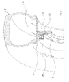
- FIG. 1 shows a typical two piece wheel assembly without a central tire inflation valve.
- the two-piece wheel assembly I includes a tire 2 with a body portion 2A and an inner cavity 2B containing a pressurized fluid (usually air).
- the wheel assembly 1 includes a rim portion 1A formed coaxially on opposite ends thereof with outwardly flaring circumferential flange sections disposed to be engaged by the beads of tubeless tire 2.
- a transverse wall section, disc portion 1B extends transversely of the axis of the wheel assembly 1 and its rim 1A, and includes a central opening (hub bore area 1C) disposed coaxially on said axis.
- the wall section of two-piece wheels includes two major parts, an outer portion (or rim half) 3 and an inner portion (or rim half) 4.
- the two portions/halves 3 and 4 are held together by fastening elements such as assembly studs 5 and assembly nuts 6 and scaled with a wheel sealing o-ring 7 placed between confronting surfaces of the two portions 3 and 4 so as to prevent air from escaping out of tire air chamber 2B (thereby creating a sealed space including tire cavity/chamber 2B).
- An inflation valve 8 is in communication with cavity 2B via an internal passageway 9, allowing controlled ingress and egress of air (or other fluids) for inflation/deflation purposes.
- FIG. 2 shows a two piece wheel assembly 10 and tire with a central tire inflation (CT1) valve 11.
- CT1 central tire inflation
- the construction of wheel 10 is the same as the one shown in FIG. 1 , except it has the CTI valve 11 added.
- the CTI valve 11 is a device used to control the pressure in tire cavity 2B according to a controlled setting from the cab of the vehicle via internal passageways 12, 13.
- these systems only cover specific pressures and the valve 11 does not totally relieve the pressure in the tire cavity 2B, and cannot serve as a safeguard in the situations outlined herein.
- Other means have also been sought to relieve the pressure in the tire such as that described in US patent number 5,343,920 .
- This system describes special assembly studs and nuts that are designed to relieve the pressure in the tire if any of the assembly nuts are removed from the vehicle.
- this system also has numerous disadvantages.
- the assembly is complex, requiring a multiplicity of components that can fail.
- studs are weakened by the o-ring sealing device of the aforesaid system.
- the assembly nuts may have to be oversized in order to seal air pressure in the system.
- multiple assembly studs must have the sealing device and corresponding cross-drills into the tire cavity.
- the design of the studs and nuts is complex, adding to the cost of this system.
- wheels having fastening elements comprising mechanical holding apparatus such as nuts and bolts (or studs) used to hold together two parts to seal the vessel comprised of the rim and a tubeless tire mounted thereon are provided with a blocking device that prevents loosening and/or removal of said nuts, bolts and/or other mechanical holding apparatus serving as fastening element(s) until said blocking device is first removed from its blocking position.
- a wheel disassembly safety system for multi-piece wheels comprises:
- This system is characterized in that it also comprises a blocking member positionable in a blocking position preventing access to at least some of said fastening elements to prevent disassembly of the pieces forming the wheel rim until the blocking member is moved from said blocking position, where movement of the blocking member from said blocking position one of: unseals said exterior opening causing depressurization of the said tubeless tire mounted on the rim, causes removal of an element sealing said exterior opening causing depressurization of the said tubeless tire mounted on the rim, and requires removal of an element sealing said exterior opening causing depressurization of the said tubeless tire mounted on the rim.
- this system may be such that at least one of:
- said blocking member may form a ring shaped member that is positionable in a blocking position to prevent access to at least some of said fastening elements to prevent disassembly of the pieces forming the wheel rim until the ring shaped member is moved from said blocking position.
- said ring shaped member may form at least a portion of one of a hub cap and a wheel cover.
- an inflation valve for the tire may be connected directly to the blocking member so as to sealingly engage the exterior opening of the air passageway when the blocking member is in the blocking position, but such that movement of the blocking member from the blocking position unseals said exterior opening causing depressurization of said tubeless tire via said air passageway.
- an inflation valve for the tire may be connected directly through the blocking member so as to sealingly engage the exterior opening of the air passageway, but such that movement of the blocking member from the blocking position requires removal of the inflation valve from sealing engagement with the exterior opening causing depressurization of said tubeless tire via said air passageway.
- the inflation valve for the tire may have a flange which blocks removal of the blocking member until the inflation valve is removed.
- a flange of an inflation valve may act as a blocking member.
- said valve may be a CTI valve.
- said safety ring may have a scalloped configuration so that only certain fastening elements are blocked.
- said wheel disassembly safety system may be such that at least one of: includes a plurality of individual safety pieces acting as blocking members, and said plurality of safety pieces are arranged to block access to a symmetrical configuration of fastening elements.
- said safety ring may be held in blocking position by its attachment to assembly studs via additional jam nuts.
- said safety ring may be at least one of: divided into separate sections, includes tabs serving to block access to fastening elements, includes stand-offs, and includes wrench blocking rings.
- an individual assembly cover may serve as a blocking member.
- the blocking device of the invention takes the form of a safety ring 20 that must be removed prior to removing the assembly nuts 6.
- the safety ring 20 illustrated covers the assembly nuts 6 so that the assembly nuts 6 cannot be removed without first removing the safety ring 20.
- the safety ring is held in place by cap screws 21.
- the safety ring 20 also directly abuts air passageway 23, holding a sealing o-ring 22 in place. This serves to seal pressure from the tire cavity 2B from escaping under normal use. However, if disassembly is attempted without first depressurizing the tire 2, removal of the safety ring 20 is required in order to access and remove nuts 6 from studs 5 and disassemble the wheel 1. Removal of ring 20 unseals and opens air passageway 23, allowing air to escape from the tire cavity 2b to the atmosphere in a controlled and safe manner. (A plurality of air channels can be used for this purpose, but only one is necessary to illustrate the inventive concept).
- FIGS. 4a and 4b features a safety ring that directly abuts air passageway 23.
- the modified safety ring 30 of FIGS. 4a and 4b only partially covers the assembly nuts 6.
- the assembly nuts 6 still cannot be removed without removing the modified safety ring 30 first, making clear the fact that a blocking device can be effective for its purposes without completely covering the mechanical holding apparatus of a sealed vessel (such as nuts 6).
- a blocking device such as safety rings 20, 30 could be used to cover any type of mechanical holding apparatus, assembly fastener or assembly ring such as assembly cap screws, side rings or lock rings.
- the blocking device or safety ring can be incorporated into a combined safety ring and hub cap/wheel cover configuration 35 as well.
- FIGS. 6 through 9b illustrate variations where the blocking device interacts with, is based upon, includes and/or is incorporated into a pressurization/depressurization valve in communication with tire cavity 2b.
- an example is provided of an inflation valve 42 directly attached to a safety ring 40 (which is modified for this purpose by the inclusion of a suitable aperture with threads 41 for use in mounting valve 42).
- the removal of the safety ring 40 will unseal the air passageway 23 normally used for inflation/deflation of tire 2 via inflation valve 42.
- This variation is advantageous as it does not require the provision of special air passageways in conjunction with the blocking device, but is enabled by the ordinary passageways by which inflation valve 42 is normally in communication with tire cavity 2b.
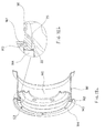
- FIG. 7 shows an inflation valve 45 with a flange 46.
- the inflation valve 45 is mounted through a clearance hole 36 in safety ring 20.
- safety ring 20 is not directly sealed to the wheel.
- the flange 46 on valve 45 (which is too large in diameter to fit through clearance hole 36) requires removal of valve 45 before safety ring 20 can be removed, thereby once again allowing depressurization via the air channel in communication with both tire cavity 2b and valve 45.
- FIGS. 8a, 8b and 9a, 9b the next two examples shown, the blocking device is actually incorporated into the pressurization/depressurization valve.
- FIGS. 8a and 8b show an inflation valve 45 with a flange 46 that partially covers one or more assembly nuts 6. In this case, removal of the inflation valve 45 is once again necessary in order to remove assembly nut 6, resulting in a loss of tire pressure.
- a CTI valve 50 similar to that shown in FIG. 2 includes a protruding section or flange 51 that completely or partially covers one or more assembly nuts 6.
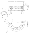
- FIGS. 10a, 10b , 11 and 12a, 12b show a safety ring 66 that is scalloped so that only certain assembly nuts 6 are blocked from removal.
- An embodiment like this might be used where both the assembly studs 5 and lug studs that attach the wheel I to the vehicle are on the same or similar bolt circle diameters.
- the scallops in safety ring 66 would allow removal of the lug nuts and removal of the wheel 1 from the vehicle without depressurizing the tire 2 but would require removal of the safety ring 66 and depressurization of the tire 2 before any of the wheel assembly nuts 6 could be removed.
- FIG. 11 shows individual safety pieces 75 with interactive safety valves 76 as opposed to a safety ring.
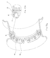
- FIGS. 12a and 12b illustrate still another embodiment of a safety ring 80.
- the safety ring 80 is directly attached to the assembly studs 5 with additional jam nuts 81.
- the safety ring 80 still covers the seal passageway to the tire. In this embodiment, removal of the jam nuts 81 and removal of the safety ring 80 will, once again, relieve the tire pressure prior to allowing disassembly of the main wheel assembly nuts 6.
Landscapes
- Engineering & Computer Science (AREA)
- Mechanical Engineering (AREA)
- Tires In General (AREA)
- Vehicle Cleaning, Maintenance, Repair, Refitting, And Outriggers (AREA)
Abstract
Description
- The purpose of this invention is to provide a safety system that relieves the pressure from a pressurized tire before removal of key components that could cause a catastrophic failure if removed while pressure remains in the tire. A typical example of the need and purpose of the invention is presented by a tubeless tire mounted on a two-piece rim. In this situation, if the assembly nuts are removed without deflating the tire first, a catastrophic failure of the remaining fasteners may occur after some of the nuts are removed, causing injury to the personnel disassembling the tire/wheel combination. Thus, a primary application of the instant invention is avoiding disastrous and sometimes explosive decompression of inflated tires on the disassembly of a two piece wheel assembled to an inflated tire.
-
FIG. 1 shows a typical two piece wheel assembly without a central tire inflation valve. The two-piece wheel assembly I includes atire 2 with a body portion 2A and an inner cavity 2B containing a pressurized fluid (usually air). Thewheel assembly 1 includes a rim portion 1A formed coaxially on opposite ends thereof with outwardly flaring circumferential flange sections disposed to be engaged by the beads oftubeless tire 2. A transverse wall section, disc portion 1B, extends transversely of the axis of thewheel assembly 1 and its rim 1A, and includes a central opening (hub bore area 1C) disposed coaxially on said axis. The wall section of two-piece wheels (disc portion 1B) includes two major parts, an outer portion (or rim half) 3 and an inner portion (or rim half) 4. The two portions/halves assembly studs 5 andassembly nuts 6 and scaled with a wheel sealing o-ring 7 placed between confronting surfaces of the twoportions inflation valve 8 is in communication with cavity 2B via aninternal passageway 9, allowing controlled ingress and egress of air (or other fluids) for inflation/deflation purposes. - With this type of construction, if some of the fastening elements such as
assembly nuts 6 are disassembled fromstuds 5, pressure is sometimes relieved in a manner that avoids the previously described consequences. This is due to the fact that loosening of some of theassembly nuts 6 may allow theouter portion 3 of thewheel assembly 1 to deflect enough that the o-ring 7 seal can leak and relieve pressure. However, as wheels become stronger and stiffer to carry higher loads or higher inflation pressures, thewheel halves assembly nuts 6 may not allow the wheel components to deflect sufficiently to release trapped air and alleviate the air pressure issue. (This is a particular problem on very large wheels and tires used for industrial applications, such as tires used on earth moving equipment, but it can also be a problem in smaller wheels and tires). In this case, after a number of theassembly nuts 6 are removed, theremaining studs 5 andnuts 6 holding thewheel assembly 1 together may fail catastrophically injuring the personnel disassembling the unit. -
FIG. 2 shows a twopiece wheel assembly 10 and tire with a central tire inflation (CT1)valve 11. The construction ofwheel 10 is the same as the one shown inFIG. 1 , except it has theCTI valve 11 added. TheCTI valve 11 is a device used to control the pressure in tire cavity 2B according to a controlled setting from the cab of the vehicle viainternal passageways valve 11 does not totally relieve the pressure in the tire cavity 2B, and cannot serve as a safeguard in the situations outlined herein. Other means have also been sought to relieve the pressure in the tire such as that described inUS patent number 5,343,920 . This system describes special assembly studs and nuts that are designed to relieve the pressure in the tire if any of the assembly nuts are removed from the vehicle. However, this system also has numerous disadvantages. First, the assembly is complex, requiring a multiplicity of components that can fail. Second, studs are weakened by the o-ring sealing device of the aforesaid system. Third, the assembly nuts may have to be oversized in order to seal air pressure in the system. Fourth, multiple assembly studs must have the sealing device and corresponding cross-drills into the tire cavity. Fifth, there are multiple leak points which reduce the liability of the system. Sixth, the design of the studs and nuts is complex, adding to the cost of this system. - The instant invention resolves and avoids these difficulties by teaching design for automatically relieving/releasing pressure from a sealed tubeless wheel/tire assembly as part of its disassembly. Thus, in the instant invention, wheels having fastening elements comprising mechanical holding apparatus such as nuts and bolts (or studs) used to hold together two parts to seal the vessel comprised of the rim and a tubeless tire mounted thereon are provided with a blocking device that prevents loosening and/or removal of said nuts, bolts and/or other mechanical holding apparatus serving as fastening element(s) until said blocking device is first removed from its blocking position. Removal directly or indirectly causes or requires the opening of a pressure relief channel or channels, which is/are advantageously formed by an air passageway in the rim, allowing, enabling and/or effecting depressurization of the sealed pressure vessel. The foregoing features and others of the inventive concept, as more fully described below, provide numerous advantages over the systems of prior art. To begin with, the described inventive concept and its variations is/are (in contrast to prior art) durable, reliable, relatively simple in construction and operation, and virtually fool-proof in terms of avoiding and preventing the types of explosive and catastrophic failures described above.
- A wheel disassembly safety system for multi-piece wheels according to the invention comprises:
- a circular wheel rim formed in pieces held together by fastening elements, said wheel rim having a flaring circumferential outer flange section formed coaxially on an outer end thereof and a flaring circumferential inner flange section formed coaxially on an inner end thereof, where said flange sections are both disposed to be engaged by beads of a tubeless tire mounted on the rim, with a transverse wall section intermediate said inner and outer ends extending transversely of the axis of said rim; and
- an air passageway in said rim in communication with an interior of the tubeless tire and having an exterior opening that can be unsealed so as to cause depressurization of said tubeless tire via said air passageway.
- This system is characterized in that it also comprises a blocking member positionable in a blocking position preventing access to at least some of said fastening elements to prevent disassembly of the pieces forming the wheel rim until the blocking member is moved from said blocking position, where movement of the blocking member from said blocking position one of: unseals said exterior opening causing depressurization of the said tubeless tire mounted on the rim, causes removal of an element sealing said exterior opening causing depressurization of the said tubeless tire mounted on the rim, and requires removal of an element sealing said exterior opening causing depressurization of the said tubeless tire mounted on the rim.
- According to another feature of the invention, this system may be such that at least one of:
- said pieces comprise an outer rim piece and an inner rim piece joined together by bolts or studs inserted through overlapping portions of said outer rim piece and said inner rim piece such that one of a head of the bolt or a nut placed thereon are accessible for loosening or tightening at the outer face of said transverse wall section and obtaining access to said nut or head of a bolt for loosening and removal requires movement of the blocking member from the blocking position,
- said blocking member sealingly abuts an exterior opening of an air passageway when in the blocking position, such that movement of the blocking member from the blocking position unseals said exterior opening causing depressurization of said tubeless tire via said air passageway,
- said blocking member is held in the blocking position by its attachment to at least one of the wheel rim, a bolt or stud inserted through overlapping rim piece portions, and the nut or head of the bolt inserted through overlapping rim piece portions,
- said blocking member prevents access to a plurality of fastening elements,
- said wheel disassembly safety system includes a plurality of blocking members, and
- one of a blocking member and a plurality of blocking members is arranged to block access to a symmetrical configuration of fastening elements.
- Advantageously, said blocking member may form a ring shaped member that is positionable in a blocking position to prevent access to at least some of said fastening elements to prevent disassembly of the pieces forming the wheel rim until the ring shaped member is moved from said blocking position.
- Also advantageously, said ring shaped member may form at least a portion of one of a hub cap and a wheel cover.
- According to an embodiment of the invention, an inflation valve for the tire may be connected directly to the blocking member so as to sealingly engage the exterior opening of the air passageway when the blocking member is in the blocking position, but such that movement of the blocking member from the blocking position unseals said exterior opening causing depressurization of said tubeless tire via said air passageway.
- According to a variant embodiment of the invention, an inflation valve for the tire may be connected directly through the blocking member so as to sealingly engage the exterior opening of the air passageway, but such that movement of the blocking member from the blocking position requires removal of the inflation valve from sealing engagement with the exterior opening causing depressurization of said tubeless tire via said air passageway. The inflation valve for the tire may have a flange which blocks removal of the blocking member until the inflation valve is removed.
- Advantageously, a flange of an inflation valve may act as a blocking member.
- Also advantageously, said valve may be a CTI valve.
- According to another embodiment of the invention, said safety ring may have a scalloped configuration so that only certain fastening elements are blocked.
- According to still another embodiment of the invention, said wheel disassembly safety system may be such that at least one of: includes a plurality of individual safety pieces acting as blocking members, and said plurality of safety pieces are arranged to block access to a symmetrical configuration of fastening elements.
- According to still another embodiment of the invention, said safety ring may be held in blocking position by its attachment to assembly studs via additional jam nuts.
- According to still another embodiment of the invention, said safety ring may be at least one of: divided into separate sections, includes tabs serving to block access to fastening elements, includes stand-offs, and includes wrench blocking rings.
- According to still another embodiment of the invention, an individual assembly cover may serve as a blocking member.
- The above-mentioned characteristics of the present invention along with the numerous other advantages of the invention will be understood more clearly on reading the following description of several examples of the invention, which are given for illustrative purposes and are not intended to limit the invention, said description referring to the attached drawings, wherein:
-
FIG. 1 provides a schematic perspective and partial cross-sectional view illustrating a typical two-piece wheel assembly with tire in accordance with the teachings of prior art. -
FIG. 2 provides a schematic perspective and partial cross-sectional view illustrating a typical two-piece wheel assembly and tire with a central tire inflation (CTI) valve in accordance with the teachings of prior art. -
FIG. 3 provides a schematic perspective and partial cross-sectional view illustrating an embodiment of the invention featuring a safety ring that must be removed prior to removing the assembly nuts. -
FIGS. 4a and 4b respectively provide schematic partial side and cross-sectional views illustrating an embodiment of the invention featuring a safety ring which only partially covers the assembly nuts. -
FIG. 5 provides a schematic perspective and partial cross-scctional view illustrating an embodiment of the invention featuring a safety ring incorporated into and/or in combination with a hub cap or wheel cover. -
FIG. 6 provides a schematic perspective and partial cross-sectional view illustrating an embodiment of the invention featuring the inflation valve directly attached to the safety ring. -
FIG. 7 provides a schematic partial cross-sectional view illustrating an embodiment of the invention featuring an inflation valve with a flange mounted through the safety ring. -
FIGS. 8a and 8b respectively provide schematic partial side and cross-sectional views illustrating an embodiment of the invention featuring an inflation valve with a flange that partially covers one or more assembly nuts. -
FIGS. 9a and 9b respectively provide schematic partial side and cross-sectional views illustrating an embodiment of the invention featuring a two-piece wheel with a CTI valve having a protruding section that completely or partially covers one or more assembly nuts. -
FIGS. 10a, 10b and 10c respectively provide schematic partial side, cross-sectional and perspective views illustrating an embodiment of the invention featuring a safety ring that is scalloped so that only certain assembly nuts are blocked from removal. -
FIG. 11 provides a schematic perspective and partial cross-sectional view illustrating an embodiment of the invention featuring individual safety pieces as opposed to a safety ring. -
FIGS. 12a and 12b respectively provide schematic partial side and cross-sectional views illustrating an embodiment of the invention featuring a safety ring directly attached to the assembly studs via additional jam nuts. -
FIGS. 13a and 13b respectively provide schematic perspective and partial cross sectional views illustrating an embodiment of the invention featuring a safety ring divided into sections and having tabs to block disassembly. -
FIGS. 14a and 14b respectively provide schematic perspective and partial cross sectional views illustrating an embodiment of the invention featuring individual protective assembly covers. -
FIGS. 15a and 15b respectively provide schematic partial side and cross sectional views illustrating an embodiment that covers the assembly studs. -
FIGS. 16a and 16b respectively provide schematic perspective and partial cross sectional views illustrating a cover that can prevent disassembly of the wheel halves if the tire is pressurized. -
FIGS. 17a and 17b respectively provide schematic perspective and partial cross sectional views illustrating another embodiment of a safety ring. -
FIGS. 18a and 18b respectively provide schematic perspective and partial cross sectional views illustrating a multi piece wheel with the safety ring feature. -
FIGS. 19a, 19b, 19c and 19d respectively provide a schematic perspective view, a side view and two partial cross sectional views according to sections XIXc-XIXc and XIXd-XIXd offigure 19b , illustrating a device that prevents removal of theassembly nuts 6 by blocking wrench access. - In
FIG. 3 the blocking device of the invention takes the form of asafety ring 20 that must be removed prior to removing the assembly nuts 6. Thesafety ring 20 illustrated covers theassembly nuts 6 so that theassembly nuts 6 cannot be removed without first removing thesafety ring 20. In the illustration shown, the safety ring is held in place by cap screws 21. Thesafety ring 20 also directly abutsair passageway 23, holding a sealing o-ring 22 in place. This serves to seal pressure from the tire cavity 2B from escaping under normal use. However, if disassembly is attempted without first depressurizing thetire 2, removal of thesafety ring 20 is required in order to access and removenuts 6 fromstuds 5 and disassemble thewheel 1. Removal ofring 20 unseals and opensair passageway 23, allowing air to escape from thetire cavity 2b to the atmosphere in a controlled and safe manner. (A plurality of air channels can be used for this purpose, but only one is necessary to illustrate the inventive concept). - The embodiment of
FIGS. 4a and 4b , like that ofFIG. 3 , features a safety ring that directly abutsair passageway 23. However, the modifiedsafety ring 30 ofFIGS. 4a and 4b only partially covers the assembly nuts 6. Theassembly nuts 6 still cannot be removed without removing the modifiedsafety ring 30 first, making clear the fact that a blocking device can be effective for its purposes without completely covering the mechanical holding apparatus of a sealed vessel (such as nuts 6). Further, thoughassembly nuts 6 are shown inFIG. 3 andFIGS. 4a and 4b , a blocking device such as safety rings 20, 30 could be used to cover any type of mechanical holding apparatus, assembly fastener or assembly ring such as assembly cap screws, side rings or lock rings. In addition, as illustrated inFIG. 5 , the blocking device or safety ring can be incorporated into a combined safety ring and hub cap/wheel cover configuration 35 as well. -
FIGS. 6 through 9b illustrate variations where the blocking device interacts with, is based upon, includes and/or is incorporated into a pressurization/depressurization valve in communication withtire cavity 2b. Thus, inFIG. 6 , an example is provided of aninflation valve 42 directly attached to a safety ring 40 (which is modified for this purpose by the inclusion of a suitable aperture withthreads 41 for use in mounting valve 42). In this case, the removal of thesafety ring 40 will unseal theair passageway 23 normally used for inflation/deflation oftire 2 viainflation valve 42. This variation is advantageous as it does not require the provision of special air passageways in conjunction with the blocking device, but is enabled by the ordinary passageways by whichinflation valve 42 is normally in communication withtire cavity 2b. Likewise,FIG. 7 shows aninflation valve 45 with aflange 46. In this configuration, theinflation valve 45 is mounted through aclearance hole 36 insafety ring 20. Thus,safety ring 20 is not directly sealed to the wheel. Instead, theflange 46 on valve 45 (which is too large in diameter to fit through clearance hole 36) requires removal ofvalve 45 beforesafety ring 20 can be removed, thereby once again allowing depressurization via the air channel in communication with bothtire cavity 2b andvalve 45. - In
FIGS. 8a, 8b and9a, 9b , the next two examples shown, the blocking device is actually incorporated into the pressurization/depressurization valve. Thus,FIGS. 8a and 8b show aninflation valve 45 with aflange 46 that partially covers one ormore assembly nuts 6. In this case, removal of theinflation valve 45 is once again necessary in order to removeassembly nut 6, resulting in a loss of tire pressure. And, inFIGS. 9a and 9b aCTI valve 50 similar to that shown inFIG. 2 includes a protruding section orflange 51 that completely or partially covers one ormore assembly nuts 6. Here, as in the embodiment illustrated inFIGS. 8a and 8b , removal of theCTI valve 50 is necessary in order to accessassembly nuts 6, resulting in depressurization oftire cavity 2b. Also, with regard toFIGS. 8a, 8b and9a, 9b where only a limited number ofassembly nuts 6 are directly covered in the embodiment shown, a simple safety ring can be placed so as to cover all or a majority of the remainingnuts 6, with removal of this assembly ring requiring (as previously specified) removal ofvalve structure - Other possible embodiments include those shown in
FIGS. 10a, 10b ,11 and12a, 12b .FIGS. 10a and 10b show asafety ring 66 that is scalloped so that onlycertain assembly nuts 6 are blocked from removal. An embodiment like this might be used where both theassembly studs 5 and lug studs that attach the wheel I to the vehicle are on the same or similar bolt circle diameters. The scallops insafety ring 66 would allow removal of the lug nuts and removal of thewheel 1 from the vehicle without depressurizing thetire 2 but would require removal of thesafety ring 66 and depressurization of thetire 2 before any of thewheel assembly nuts 6 could be removed.FIG. 11 showsindividual safety pieces 75 withinteractive safety valves 76 as opposed to a safety ring. Theindividual pieces 75 may cover a more limited number ofassembly nuts 6 as opposed to all of theassembly nuts 6 and still be effective for their intended purpose.FIGS. 12a and 12b illustrate still another embodiment of asafety ring 80. In this embodiment, thesafety ring 80 is directly attached to theassembly studs 5 with additional jam nuts 81. Thesafety ring 80 still covers the seal passageway to the tire. In this embodiment, removal of thejam nuts 81 and removal of thesafety ring 80 will, once again, relieve the tire pressure prior to allowing disassembly of the main wheel assembly nuts 6. -
FIGS. 13a and 13b illustrate another embodiment of asafety ring 90 withtabs 92. Thesafety ring 90 may be made in one or more parts (as illustrated) such that the tabs cover the assembly nuts to prevent disassembly. Thesafety ring 90 is secured to the wheel via screws 91. Thesafety ring 90 seals offair passageway 23 via o-ring 22. -
FIGS. 14a and 14b illustrate an embodiment where individual covers 100 prevent disassembly unless the air pressure is relieved. Thecovers 100 screw ontoassembly studs 5 viathreads 101 and cover assembly nuts 6. They also seal offindividual air passageways 23 via o-rings 22. Some or allassembly nuts 6 may be covered. -
FIGS. 15a and 15b illustrate an embodiment where some or allassembly nuts 6 are covered bysafety ring 110.Safety ring 110 is attached to the wheel by jam nuts 111 I and sealair passageway 23 via o-ring 22. -
FIGS. 16a and 16b illustrate an embodiment where thewheel cover 120 blocks disassembly of assembly nuts 6. Thecover 120 may be attached to theouter wheel half 3 orinner wheel half 4 by any number of means. On such means of attachment is shown as stiffeningring 121 and screws 122. -
FIGS. 17a and 17b illustrate asafety ring 130 attached to the wheel withscrews 131.Safety ring 130 may usestand offs 132 to elevate the ring. -
FIGS. 18a and 18b illustrate asafety ring 144 attached to amulti piece wheel 140. Themulti-piece wheel 140 may consist of arim base 141 andside ring 142. Some multi-piece wheels also utilize alock ring 143. Wheels like this are typically made from steel and are disassembled by removing thesplit lock ring 143 andside ring 143. Alternatively the side ring and lock ring can be combined into one split side ring that snaps into the groove in therim base 141. In either wheel configuration thesafety ring 144 prevents disassembly of thelock ring 143 orside ring 142 without first removingscrews 122 and allowing air to escape viapassageway 23. -
FIGS. 19a to 19d illustrate awrench blocking ring 150 that prevents wrench access to assembly nuts 6. Thescrews 151 attach thewrench blocking ring 150 to the wheel to seal offair passageway 23 via o-ring 22. Since wrench access toassembly nuts 6 is blocked by thering 150, the assembly nuts cannot be removed. It will be apparent to anyone skilled in the art that variety of wrench blocking configurations can be designed without departing from the spirit of the invention. - The previously described advantages and features of the invention are advantageously provided through and using the preferred embodiments previously illustrated and discussed. However, it should be clear to anyone knowledgeable about wheels that a variety of configurations may be utilized without departing from the spirit of the invention. Moreover, though tire-wheel assemblies typically utilize air as the pressurized fluid, it is clear that any pressurized fluid (gas or liquid) can be used. Moreover, the safety ring of the invention need not take the form illustrated in order to serve its purpose as a blocking member. It can, for example, be constructed as a safety wire to minimize weight.
- Thus, numerous additional variations are possible without deviating from and/or exceeding the spirit and scope of the invention. Moreover, various features and functions disclosed above, or alternatives thereof, may be desirably combined into many other different systems or applications.
- Finally, the following parts list for the drawing figures may be found to be of assistance in understanding more fully the concepts of the invention:
- 1
- two-piece wheel assembly (without CTIS)
- 1A
- rim portion
- 1B
- disc portion
- 1C
- hub bore area
- 2
- Tubeless tire
- 2a
- Tire body
- 2b
- Tire cavity
- 3
- Outer wheel half
- 4
- Inner wheel half
- 5
- Assembly stud
- 6
- Assembly nut
- 7
- Wheel sealing o-ring
- 8
- inflation valve
- 9
- Internal passageway
- 10
- 2-piece wheel assembly with CTIS
- 11
- CTI valve
- 12
- Internal passageway
- 13
- Internal passageway
- 20
- Safety ring
- 21
- Cap screw
- 22
- Sealing o-ring
- 23
- Air passageway
- 30
- Safety ring that partially covers assembly nuts
- 35
- Hub cap or wheel cover
- 36
- Clearance hole for inflation valve
- 40
- Safety ring for inflation valve
- 41
- Threads for inflation valve
- 42
- Inflation valve
- 45
- Inflation valve with flange
- 46
- Inflation valve
- 50
- CTI valve with flange
- 51
- Flange
- 65
- 2-piece wheel assembly with scalloped safety shield
- 66
- Scalloped safety shield
- 67
- Attachment screws
- 68
- Sleeve for attachment screws
- 69
- Pin to block air
- 70
- Lug nuts (attaches wheel to vehicle hub)
- 75
- Individual safety shields
- 76
- Safety valves
- 80
- Safety ring
- 81
- Jam nuts
Claims (14)
- A wheel disassembly safety system for multi-piece wheels (10, 140), comprising:- a circular wheel rim formed in pieces (3 and 4) held together by fastening elements (6), said wheel rim having a flaring circumferential outer flange section formed coaxially on an outer end thereof and a flaring circumferential inner flange section formed coaxially on an inner end thereof, where said flange sections are both disposed to be engaged by beads of a tubeless tire (2) mounted on the rim, with a transverse wall section intermediate said inner and outer ends extending transversely of the axis of said rim; and- an air passageway (23) in said rim in communication with an interior of the tubeless tire and having an exterior opening that can be unsealed so as to cause depressurization of said tubeless tire via said air passageway;characterized in that the system also comprises a blocking member (20, 30, 40, 50, 66, 75, 80, 90, 100, 110, 120, 130, 144, 150) positionable in a blocking position preventing access to at least some of said fastening elements to prevent disassembly of the pieces forming the wheel rim until the blocking member is moved from said blocking position, where movement of the blocking member from said blocking position one of: unseals said exterior opening causing depressurization of the said tubeless tire mounted on the rim, causes removal of an element sealing said exterior opening causing depressurization of the said tubeless tire mounted on the rim, and requires removal of an element sealing said exterior opening causing depressurization of the said tubeless tire mounted on the rim.
- A wheel disassembly safety system as described in claim 1, wherein at least one of:- said pieces (3 and 4) comprise an outer rim piece and an inner rim piece joined together by bolts or studs (5, 6) inserted through overlapping portions of said outer rim piece and said inner rim piece such that one of a head of the bolt or a nut placed thereon are accessible for loosening or tightening at the outer face of said transverse wall section and obtaining access to said nut or head of a bolt for loosening and removal requires movement of the blocking member (20, 30, 40, 50, 66, 75, 80, 90, 100, 110, 120, 130, 144, 150) from the blocking position,- said blocking member sealingly abuts an exterior opening of an air passageway (23) when in the blocking position, such that movement of the blocking member from the blocking position unseals said exterior opening causing depressurization of said tubeless tire (2) via said air passageway,- said blocking member is held in the blocking position by its attachment to at least one of the wheel rim, a bolt or stud inserted through overlapping rim piece portions, and the nut or head of the bolt inserted through overlapping rim piece portions,- said blocking member prevents access to a plurality of fastening elements (6),- said wheel disassembly safety system includes a plurality of blocking members, and- one of a blocking member and a plurality of blocking members is arranged to block access to a symmetrical configuration of fastening elements.
- A wheel disassembly safety system as described in claim 1 or 2, wherein said blocking member (20, 30, 40, 50, 66, 80, 90, 110, 120, 130, 144, 150) forms a ring shaped member that is positionable in a blocking position to prevent access to at least some of said fastening elements (6) to prevent disassembly of the pieces (3 and 4) forming the wheel rim until the ring shaped member is moved from said blocking position.
- A wheel disassembly safety system as described in claim 3, wherein said ring shaped member (20, 30, 40, 50, 66, 80, 90, 110, 120, 130, 144, 150) forms at least a portion of one of a hub cap and a wheel cover.
- A wheel disassembly safety system as described in claim 1 or 2, wherein an inflation valve (42) for the tire (2) is connected directly to the blocking member (40) so as to sealingly engage the exterior opening of the air passageway (23) when the blocking member is in the blocking position, but such that movement of the blocking member from the blocking position unseals said exterior opening causing depressurization of said tubeless tire via said air passageway.
- A wheel disassembly safety system as described in claim 1 or 2, wherein an inflation valve (45) for the tire (2) is connected directly through the blocking member so as to sealingly engage the exterior opening of the air passageway (23), but such that movement of the blocking member (20) from the blocking position requires removal of the inflation valve from sealing engagement with the exterior opening causing depressurization of said tubeless tire via said air passageway.
- A wheel disassembly safety system as described in claim 6, wherein the inflation valve (45) for the tire (2) has a flange (46) which blocks removal of the blocking member (20) until the inflation valve is removed.
- A wheel disassembly safety system as described in claim 1 or 2, wherein a flange (46) of an inflation valve (45) acts as a blocking member.
- A wheel disassembly safety system as described in claim 8, wherein said valve is a CTI valve (50).
- A wheel disassembly safety system as described in claim 3, wherein said safety ring (66) has a scalloped configuration so that only certain fastening elements (6) are blocked.
- A wheel disassembly safety system as described in claim 2, wherein said wheel disassembly safety system at least one of: includes a plurality of individual safety pieces (75) acting as blocking members, and said plurality of safety pieces are arranged to block access to a symmetrical configuration of fastening elements (6).
- A wheel disassembly safety system as described in claim 3, wherein said safety ring (80) is held in blocking position by its attachment to assembly studs (5) via additional jam nuts (81).
- A wheel disassembly safety system as described in claim 3, wherein said safety ring (90) is at least one of: divided into separate sections, includes tabs (92) serving to block access to fastening elements (6), includes stand-offs, and includes wrench blocking rings.
- A wheel disassembly safety system as described in claim 1 or 2, wherein an individual assembly cover (120) serves as a blocking member.
Priority Applications (1)
| Application Number | Priority Date | Filing Date | Title |
|---|---|---|---|
| PL10169848T PL2279881T3 (en) | 2009-07-31 | 2010-07-16 | Wheel disassembly safety system |
Applications Claiming Priority (1)
| Application Number | Priority Date | Filing Date | Title |
|---|---|---|---|
| US27314109P | 2009-07-31 | 2009-07-31 |
Publications (3)
| Publication Number | Publication Date |
|---|---|
| EP2279881A2 true EP2279881A2 (en) | 2011-02-02 |
| EP2279881A3 EP2279881A3 (en) | 2011-10-19 |
| EP2279881B1 EP2279881B1 (en) | 2013-03-13 |
Family
ID=42813274
Family Applications (1)
| Application Number | Title | Priority Date | Filing Date |
|---|---|---|---|
| EP10169848A Active EP2279881B1 (en) | 2009-07-31 | 2010-07-16 | Wheel disassembly safety system |
Country Status (5)
| Country | Link |
|---|---|
| US (1) | US8505598B2 (en) |
| EP (1) | EP2279881B1 (en) |
| AU (1) | AU2010203056B2 (en) |
| CA (1) | CA2712154C (en) |
| PL (1) | PL2279881T3 (en) |
Cited By (4)
| Publication number | Priority date | Publication date | Assignee | Title |
|---|---|---|---|---|
| CN104354527A (en) * | 2014-09-30 | 2015-02-18 | 徐州重型机械有限公司 | Rim for heavy engineering machinery vehicle and heavy engineering machinery vehicle |
| WO2016049831A1 (en) * | 2014-09-30 | 2016-04-07 | 徐州重型机械有限公司 | Rim for heavy engineering machinery vehicle and heavy engineering machinery vehicle |
| EP3081389A3 (en) * | 2015-04-14 | 2017-10-18 | Goodrich Corporation | Safety deflation wheel seal design |
| WO2020206144A1 (en) * | 2019-04-05 | 2020-10-08 | Otr Wheel Engineering, Inc. | Bolt together wheel with deflation system |
Families Citing this family (10)
| Publication number | Priority date | Publication date | Assignee | Title |
|---|---|---|---|---|
| JP5427766B2 (en) * | 2010-12-21 | 2014-02-26 | 三菱重工業株式会社 | Vehicle wheel, traveling wheel, vehicle, and method for assembling and disassembling vehicle wheel |
| US8690265B2 (en) | 2011-05-19 | 2014-04-08 | Hutchinson, Sa | Dual wheels with common hub adapter |
| US8833694B2 (en) * | 2011-06-14 | 2014-09-16 | Neal Gilleran | Split circumference aircraft wheel assembly with integrated drive motor assembly |
| PL2805832T3 (en) * | 2012-01-20 | 2017-12-29 | Chengdu Youyang Electromechanical Product Design Co., Ltd. | Wheel hub, wheel hub motor vehicle wheel, and electric vehicle |
| EP3012115A4 (en) * | 2013-06-19 | 2017-03-08 | Chengdu Youyang Electromechanical Product Design Co. Ltd. | Rotating mechanism with elastic protective casing |
| FR3019144B1 (en) * | 2014-03-28 | 2016-04-01 | Messier Bugatti Dowty | AIRCRAFT WHEEL HAVING A CHANNEL ORGANIZING A LEAKAGE PATH IN THE WHEEL |
| US9937748B2 (en) * | 2015-04-09 | 2018-04-10 | Patrick Norton | Bead lock systems and methods |
| US10006466B2 (en) | 2015-04-13 | 2018-06-26 | United Technologies Corporation | Clamped HPC seal ring |
| BR112021014483A2 (en) * | 2019-01-23 | 2021-09-28 | Hutchinson Industries, Inc. | SAFETY SYSTEM AGAINST EMPTYING |
| JP7307280B2 (en) * | 2019-12-30 | 2023-07-11 | ブリヂストン アメリカズ タイヤ オペレーションズ、 エルエルシー | Bump stop for non-pneumatic tires |
Citations (1)
| Publication number | Priority date | Publication date | Assignee | Title |
|---|---|---|---|---|
| US5343920A (en) | 1991-08-26 | 1994-09-06 | The Goodyear Tire & Rubber Company | Wheel assembly with flange securing and pressure relieving means |
Family Cites Families (14)
| Publication number | Priority date | Publication date | Assignee | Title |
|---|---|---|---|---|
| US2229724A (en) * | 1939-08-24 | 1941-01-28 | Clark Equipment Co | Wheel |
| US2252194A (en) * | 1939-08-25 | 1941-08-12 | Clark Equipment Co | Wheel |
| US2428551A (en) * | 1942-12-19 | 1947-10-07 | Clark Equipment Co | Safety wheel |
| US3831658A (en) | 1973-09-17 | 1974-08-27 | Caterpillar Tractor Co | Tire removal means |
| US3882919A (en) * | 1973-12-13 | 1975-05-13 | Caterpillar Tractor Co | Safety rim |
| US3990494A (en) | 1975-09-02 | 1976-11-09 | Caterpillar Tractor Co. | Tire removal means with safety lock |
| US4043374A (en) | 1975-12-17 | 1977-08-23 | Caterpillar Tractor Co. | Wheel rim assembly and method for demounting a tire therefrom |
| DE2709160C3 (en) | 1977-03-03 | 1981-04-30 | Continental Gummi-Werke Ag, 3000 Hannover | Vehicle wheel with a tubeless pneumatic tire and a detachably attached rim ring |
| US4123112A (en) | 1977-07-18 | 1978-10-31 | Titan Proform Company Limited | Split wheel safety feature |
| US4836261A (en) * | 1987-03-27 | 1989-06-06 | Motor Wheel Corporation | Safety tire and take-apart wheel construction |
| US7083238B2 (en) | 2004-08-23 | 2006-08-01 | Alcoa, Inc. | Multi-piece aluminum wheel and associated method |
| FI117550B (en) * | 2004-12-08 | 2006-11-30 | Sandvik Tamrock Oy | Method and apparatus for increasing safety in wheel handling |
| US7779877B2 (en) * | 2008-05-27 | 2010-08-24 | Hayes Lemmerz International, Inc. | Take apart vehicle wheel assembly |
| US8087439B2 (en) * | 2008-06-13 | 2012-01-03 | Hutchinson, S.A. | Wheel with integrated and non-integrated central tire inflation |
-
2010
- 2010-05-24 US US12/786,094 patent/US8505598B2/en active Active
- 2010-07-16 AU AU2010203056A patent/AU2010203056B2/en active Active
- 2010-07-16 PL PL10169848T patent/PL2279881T3/en unknown
- 2010-07-16 EP EP10169848A patent/EP2279881B1/en active Active
- 2010-07-30 CA CA2712154A patent/CA2712154C/en active Active
Patent Citations (1)
| Publication number | Priority date | Publication date | Assignee | Title |
|---|---|---|---|---|
| US5343920A (en) | 1991-08-26 | 1994-09-06 | The Goodyear Tire & Rubber Company | Wheel assembly with flange securing and pressure relieving means |
Cited By (8)
| Publication number | Priority date | Publication date | Assignee | Title |
|---|---|---|---|---|
| CN104354527A (en) * | 2014-09-30 | 2015-02-18 | 徐州重型机械有限公司 | Rim for heavy engineering machinery vehicle and heavy engineering machinery vehicle |
| WO2016049831A1 (en) * | 2014-09-30 | 2016-04-07 | 徐州重型机械有限公司 | Rim for heavy engineering machinery vehicle and heavy engineering machinery vehicle |
| EP3081389A3 (en) * | 2015-04-14 | 2017-10-18 | Goodrich Corporation | Safety deflation wheel seal design |
| US9821600B2 (en) | 2015-04-14 | 2017-11-21 | Goodrich Corporation | Safety deflation wheel seal design |
| WO2020206144A1 (en) * | 2019-04-05 | 2020-10-08 | Otr Wheel Engineering, Inc. | Bolt together wheel with deflation system |
| CN113891807A (en) * | 2019-04-05 | 2022-01-04 | 奥特车轮工程公司 | Bolt connecting wheel with air discharging system |
| CN113891807B (en) * | 2019-04-05 | 2023-08-22 | 奥特车轮工程公司 | Bolted wheels with deflation system |
| US12097725B2 (en) | 2019-04-05 | 2024-09-24 | Otr Wheel Engineering, Inc. | Bolt together wheel with deflation system |
Also Published As
| Publication number | Publication date |
|---|---|
| US20110057503A1 (en) | 2011-03-10 |
| PL2279881T3 (en) | 2013-08-30 |
| CA2712154A1 (en) | 2011-01-31 |
| CA2712154C (en) | 2017-09-19 |
| US8505598B2 (en) | 2013-08-13 |
| AU2010203056A1 (en) | 2011-02-17 |
| EP2279881A3 (en) | 2011-10-19 |
| EP2279881B1 (en) | 2013-03-13 |
| AU2010203056B2 (en) | 2016-06-23 |
Similar Documents
| Publication | Publication Date | Title |
|---|---|---|
| EP2279881B1 (en) | Wheel disassembly safety system | |
| US20200231001A1 (en) | Deflation safety system and system including same | |
| EP1266165B1 (en) | Valve with pressure indicator | |
| JP2008510657A (en) | Multi-piece safety wheel and associated method | |
| CN113891807B (en) | Bolted wheels with deflation system | |
| WO2012075588A1 (en) | Apparatus and method for testing pressure relief valves | |
| US10371282B2 (en) | Shaft blowout prevention device | |
| US9303806B2 (en) | Closure assembly for pipe end | |
| US9566832B2 (en) | Hub adapter and central tire inflation system including same | |
| US3991804A (en) | Thermal pressure relief apparatus for tire and rim assembly | |
| US4682640A (en) | Circumferential conduit means for inflating a closed torus tire | |
| US7451794B1 (en) | Internal air passage in a take-apart wheel | |
| JP4726910B2 (en) | Method and apparatus for improving safety in wheel handling | |
| EP1305198B1 (en) | Pressure relief device | |
| AU2008258642B2 (en) | Purge valve for mounted assembly | |
| EP4385751A1 (en) | Corrosion protection for aircraft wheel pneumatic ports | |
| CA1215618A (en) | Circumferential conduit means for inflating a closed torus tire | |
| MXPA99007786A (en) | Safety vent for railroad tank cars |
Legal Events
| Date | Code | Title | Description |
|---|---|---|---|
| PUAI | Public reference made under article 153(3) epc to a published international application that has entered the european phase |
Free format text: ORIGINAL CODE: 0009012 |
|
| AK | Designated contracting states |
Kind code of ref document: A2 Designated state(s): AL AT BE BG CH CY CZ DE DK EE ES FI FR GB GR HR HU IE IS IT LI LT LU LV MC MK MT NL NO PL PT RO SE SI SK SM TR |
|
| AX | Request for extension of the european patent |
Extension state: BA ME RS |
|
| PUAL | Search report despatched |
Free format text: ORIGINAL CODE: 0009013 |
|
| AK | Designated contracting states |
Kind code of ref document: A3 Designated state(s): AL AT BE BG CH CY CZ DE DK EE ES FI FR GB GR HR HU IE IS IT LI LT LU LV MC MK MT NL NO PL PT RO SE SI SK SM TR |
|
| AX | Request for extension of the european patent |
Extension state: BA ME RS |
|
| RIC1 | Information provided on ipc code assigned before grant |
Ipc: B60B 25/22 20060101AFI20110913BHEP |
|
| 17P | Request for examination filed |
Effective date: 20120326 |
|
| REG | Reference to a national code |
Ref country code: DE Ref legal event code: R079 Ref document number: 602010005391 Country of ref document: DE Free format text: PREVIOUS MAIN CLASS: B60B0025220000 Ipc: B60B0025000000 |
|
| RIC1 | Information provided on ipc code assigned before grant |
Ipc: B60B 25/22 20060101ALI20121004BHEP Ipc: B60B 25/00 20060101AFI20121004BHEP |
|
| GRAP | Despatch of communication of intention to grant a patent |
Free format text: ORIGINAL CODE: EPIDOSNIGR1 |
|
| GRAS | Grant fee paid |
Free format text: ORIGINAL CODE: EPIDOSNIGR3 |
|
| GRAA | (expected) grant |
Free format text: ORIGINAL CODE: 0009210 |
|
| AK | Designated contracting states |
Kind code of ref document: B1 Designated state(s): AL AT BE BG CH CY CZ DE DK EE ES FI FR GB GR HR HU IE IS IT LI LT LU LV MC MK MT NL NO PL PT RO SE SI SK SM TR |
|
| REG | Reference to a national code |
Ref country code: GB Ref legal event code: FG4D |
|
| REG | Reference to a national code |
Ref country code: AT Ref legal event code: REF Ref document number: 600556 Country of ref document: AT Kind code of ref document: T Effective date: 20130315 Ref country code: CH Ref legal event code: EP |
|
| REG | Reference to a national code |
Ref country code: IE Ref legal event code: FG4D |
|
| REG | Reference to a national code |
Ref country code: DE Ref legal event code: R096 Ref document number: 602010005391 Country of ref document: DE Effective date: 20130508 |
|
| REG | Reference to a national code |
Ref country code: CH Ref legal event code: NV Representative=s name: ISLER AND PEDRAZZINI AG, CH |
|
| PG25 | Lapsed in a contracting state [announced via postgrant information from national office to epo] |
Ref country code: NO Free format text: LAPSE BECAUSE OF FAILURE TO SUBMIT A TRANSLATION OF THE DESCRIPTION OR TO PAY THE FEE WITHIN THE PRESCRIBED TIME-LIMIT Effective date: 20130613 Ref country code: SE Free format text: LAPSE BECAUSE OF FAILURE TO SUBMIT A TRANSLATION OF THE DESCRIPTION OR TO PAY THE FEE WITHIN THE PRESCRIBED TIME-LIMIT Effective date: 20130313 Ref country code: LT Free format text: LAPSE BECAUSE OF FAILURE TO SUBMIT A TRANSLATION OF THE DESCRIPTION OR TO PAY THE FEE WITHIN THE PRESCRIBED TIME-LIMIT Effective date: 20130313 Ref country code: BG Free format text: LAPSE BECAUSE OF FAILURE TO SUBMIT A TRANSLATION OF THE DESCRIPTION OR TO PAY THE FEE WITHIN THE PRESCRIBED TIME-LIMIT Effective date: 20130613 Ref country code: ES Free format text: LAPSE BECAUSE OF FAILURE TO SUBMIT A TRANSLATION OF THE DESCRIPTION OR TO PAY THE FEE WITHIN THE PRESCRIBED TIME-LIMIT Effective date: 20130624 |
|
| REG | Reference to a national code |
Ref country code: NL Ref legal event code: T3 |
|
| REG | Reference to a national code |
Ref country code: LT Ref legal event code: MG4D |
|
| PG25 | Lapsed in a contracting state [announced via postgrant information from national office to epo] |
Ref country code: SI Free format text: LAPSE BECAUSE OF FAILURE TO SUBMIT A TRANSLATION OF THE DESCRIPTION OR TO PAY THE FEE WITHIN THE PRESCRIBED TIME-LIMIT Effective date: 20130313 Ref country code: GR Free format text: LAPSE BECAUSE OF FAILURE TO SUBMIT A TRANSLATION OF THE DESCRIPTION OR TO PAY THE FEE WITHIN THE PRESCRIBED TIME-LIMIT Effective date: 20130614 Ref country code: LV Free format text: LAPSE BECAUSE OF FAILURE TO SUBMIT A TRANSLATION OF THE DESCRIPTION OR TO PAY THE FEE WITHIN THE PRESCRIBED TIME-LIMIT Effective date: 20130313 |
|
| REG | Reference to a national code |
Ref country code: PL Ref legal event code: T3 |
|
| PG25 | Lapsed in a contracting state [announced via postgrant information from national office to epo] |
Ref country code: BE Free format text: LAPSE BECAUSE OF FAILURE TO SUBMIT A TRANSLATION OF THE DESCRIPTION OR TO PAY THE FEE WITHIN THE PRESCRIBED TIME-LIMIT Effective date: 20130313 Ref country code: HR Free format text: LAPSE BECAUSE OF FAILURE TO SUBMIT A TRANSLATION OF THE DESCRIPTION OR TO PAY THE FEE WITHIN THE PRESCRIBED TIME-LIMIT Effective date: 20130313 |
|
| PG25 | Lapsed in a contracting state [announced via postgrant information from national office to epo] |
Ref country code: EE Free format text: LAPSE BECAUSE OF FAILURE TO SUBMIT A TRANSLATION OF THE DESCRIPTION OR TO PAY THE FEE WITHIN THE PRESCRIBED TIME-LIMIT Effective date: 20130313 Ref country code: CZ Free format text: LAPSE BECAUSE OF FAILURE TO SUBMIT A TRANSLATION OF THE DESCRIPTION OR TO PAY THE FEE WITHIN THE PRESCRIBED TIME-LIMIT Effective date: 20130313 Ref country code: RO Free format text: LAPSE BECAUSE OF FAILURE TO SUBMIT A TRANSLATION OF THE DESCRIPTION OR TO PAY THE FEE WITHIN THE PRESCRIBED TIME-LIMIT Effective date: 20130313 Ref country code: IS Free format text: LAPSE BECAUSE OF FAILURE TO SUBMIT A TRANSLATION OF THE DESCRIPTION OR TO PAY THE FEE WITHIN THE PRESCRIBED TIME-LIMIT Effective date: 20130713 Ref country code: PT Free format text: LAPSE BECAUSE OF FAILURE TO SUBMIT A TRANSLATION OF THE DESCRIPTION OR TO PAY THE FEE WITHIN THE PRESCRIBED TIME-LIMIT Effective date: 20130715 Ref country code: SK Free format text: LAPSE BECAUSE OF FAILURE TO SUBMIT A TRANSLATION OF THE DESCRIPTION OR TO PAY THE FEE WITHIN THE PRESCRIBED TIME-LIMIT Effective date: 20130313 |
|
| PLBE | No opposition filed within time limit |
Free format text: ORIGINAL CODE: 0009261 |
|
| STAA | Information on the status of an ep patent application or granted ep patent |
Free format text: STATUS: NO OPPOSITION FILED WITHIN TIME LIMIT |
|
| PG25 | Lapsed in a contracting state [announced via postgrant information from national office to epo] |
Ref country code: DK Free format text: LAPSE BECAUSE OF FAILURE TO SUBMIT A TRANSLATION OF THE DESCRIPTION OR TO PAY THE FEE WITHIN THE PRESCRIBED TIME-LIMIT Effective date: 20130313 |
|
| 26N | No opposition filed |
Effective date: 20131216 |
|
| PG25 | Lapsed in a contracting state [announced via postgrant information from national office to epo] |
Ref country code: MC Free format text: LAPSE BECAUSE OF FAILURE TO SUBMIT A TRANSLATION OF THE DESCRIPTION OR TO PAY THE FEE WITHIN THE PRESCRIBED TIME-LIMIT Effective date: 20130313 |
|
| REG | Reference to a national code |
Ref country code: DE Ref legal event code: R097 Ref document number: 602010005391 Country of ref document: DE Effective date: 20131216 |
|
| REG | Reference to a national code |
Ref country code: IE Ref legal event code: MM4A |
|
| PG25 | Lapsed in a contracting state [announced via postgrant information from national office to epo] |
Ref country code: IE Free format text: LAPSE BECAUSE OF NON-PAYMENT OF DUE FEES Effective date: 20130716 |
|
| GBPC | Gb: european patent ceased through non-payment of renewal fee |
Effective date: 20140716 |
|
| PG25 | Lapsed in a contracting state [announced via postgrant information from national office to epo] |
Ref country code: GB Free format text: LAPSE BECAUSE OF NON-PAYMENT OF DUE FEES Effective date: 20140716 Ref country code: SM Free format text: LAPSE BECAUSE OF FAILURE TO SUBMIT A TRANSLATION OF THE DESCRIPTION OR TO PAY THE FEE WITHIN THE PRESCRIBED TIME-LIMIT Effective date: 20130313 |
|
| REG | Reference to a national code |
Ref country code: FR Ref legal event code: PLFP Year of fee payment: 6 |
|
| PG25 | Lapsed in a contracting state [announced via postgrant information from national office to epo] |
Ref country code: MT Free format text: LAPSE BECAUSE OF FAILURE TO SUBMIT A TRANSLATION OF THE DESCRIPTION OR TO PAY THE FEE WITHIN THE PRESCRIBED TIME-LIMIT Effective date: 20130313 Ref country code: CY Free format text: LAPSE BECAUSE OF FAILURE TO SUBMIT A TRANSLATION OF THE DESCRIPTION OR TO PAY THE FEE WITHIN THE PRESCRIBED TIME-LIMIT Effective date: 20130313 |
|
| PG25 | Lapsed in a contracting state [announced via postgrant information from national office to epo] |
Ref country code: MK Free format text: LAPSE BECAUSE OF FAILURE TO SUBMIT A TRANSLATION OF THE DESCRIPTION OR TO PAY THE FEE WITHIN THE PRESCRIBED TIME-LIMIT Effective date: 20130313 Ref country code: HU Free format text: LAPSE BECAUSE OF FAILURE TO SUBMIT A TRANSLATION OF THE DESCRIPTION OR TO PAY THE FEE WITHIN THE PRESCRIBED TIME-LIMIT; INVALID AB INITIO Effective date: 20100716 Ref country code: LU Free format text: LAPSE BECAUSE OF NON-PAYMENT OF DUE FEES Effective date: 20130716 |
|
| REG | Reference to a national code |
Ref country code: FR Ref legal event code: PLFP Year of fee payment: 7 |
|
| REG | Reference to a national code |
Ref country code: FR Ref legal event code: PLFP Year of fee payment: 8 |
|
| REG | Reference to a national code |
Ref country code: FR Ref legal event code: PLFP Year of fee payment: 9 |
|
| PG25 | Lapsed in a contracting state [announced via postgrant information from national office to epo] |
Ref country code: AL Free format text: LAPSE BECAUSE OF FAILURE TO SUBMIT A TRANSLATION OF THE DESCRIPTION OR TO PAY THE FEE WITHIN THE PRESCRIBED TIME-LIMIT Effective date: 20130313 |
|
| PGFP | Annual fee paid to national office [announced via postgrant information from national office to epo] |
Ref country code: FR Payment date: 20210622 Year of fee payment: 12 |
|
| PGFP | Annual fee paid to national office [announced via postgrant information from national office to epo] |
Ref country code: NL Payment date: 20210721 Year of fee payment: 12 |
|
| PGFP | Annual fee paid to national office [announced via postgrant information from national office to epo] |
Ref country code: IT Payment date: 20210727 Year of fee payment: 12 Ref country code: AT Payment date: 20210722 Year of fee payment: 12 Ref country code: FI Payment date: 20210722 Year of fee payment: 12 |
|
| PGFP | Annual fee paid to national office [announced via postgrant information from national office to epo] |
Ref country code: CH Payment date: 20210721 Year of fee payment: 12 Ref country code: TR Payment date: 20210714 Year of fee payment: 12 Ref country code: PL Payment date: 20210713 Year of fee payment: 12 |
|
| REG | Reference to a national code |
Ref country code: CH Ref legal event code: PL |
|
| REG | Reference to a national code |
Ref country code: NL Ref legal event code: MM Effective date: 20220801 |
|
| REG | Reference to a national code |
Ref country code: AT Ref legal event code: MM01 Ref document number: 600556 Country of ref document: AT Kind code of ref document: T Effective date: 20220716 |
|
| PG25 | Lapsed in a contracting state [announced via postgrant information from national office to epo] |
Ref country code: LI Free format text: LAPSE BECAUSE OF NON-PAYMENT OF DUE FEES Effective date: 20220731 Ref country code: FR Free format text: LAPSE BECAUSE OF NON-PAYMENT OF DUE FEES Effective date: 20220731 Ref country code: FI Free format text: LAPSE BECAUSE OF NON-PAYMENT OF DUE FEES Effective date: 20220716 Ref country code: CH Free format text: LAPSE BECAUSE OF NON-PAYMENT OF DUE FEES Effective date: 20220731 Ref country code: AT Free format text: LAPSE BECAUSE OF NON-PAYMENT OF DUE FEES Effective date: 20220716 |
|
| PG25 | Lapsed in a contracting state [announced via postgrant information from national office to epo] |
Ref country code: NL Free format text: LAPSE BECAUSE OF NON-PAYMENT OF DUE FEES Effective date: 20220801 |
|
| P01 | Opt-out of the competence of the unified patent court (upc) registered |
Effective date: 20230526 |
|
| PG25 | Lapsed in a contracting state [announced via postgrant information from national office to epo] |
Ref country code: IT Free format text: LAPSE BECAUSE OF NON-PAYMENT OF DUE FEES Effective date: 20220716 |
|
| PG25 | Lapsed in a contracting state [announced via postgrant information from national office to epo] |
Ref country code: PL Free format text: LAPSE BECAUSE OF NON-PAYMENT OF DUE FEES Effective date: 20220716 |
|
| PG25 | Lapsed in a contracting state [announced via postgrant information from national office to epo] |
Ref country code: TR Free format text: LAPSE BECAUSE OF NON-PAYMENT OF DUE FEES Effective date: 20220716 |
|
| PGFP | Annual fee paid to national office [announced via postgrant information from national office to epo] |
Ref country code: DE Payment date: 20250722 Year of fee payment: 16 |