EP2279858A1 - Fuel hose - Google Patents
Fuel hose Download PDFInfo
- Publication number
- EP2279858A1 EP2279858A1 EP09750603A EP09750603A EP2279858A1 EP 2279858 A1 EP2279858 A1 EP 2279858A1 EP 09750603 A EP09750603 A EP 09750603A EP 09750603 A EP09750603 A EP 09750603A EP 2279858 A1 EP2279858 A1 EP 2279858A1
- Authority
- EP
- European Patent Office
- Prior art keywords
- layer
- rubber
- fuel
- nbr
- fuel hose
- Prior art date
- Legal status (The legal status is an assumption and is not a legal conclusion. Google has not performed a legal analysis and makes no representation as to the accuracy of the status listed.)
- Withdrawn
Links
Images
Classifications
-
- B—PERFORMING OPERATIONS; TRANSPORTING
- B32—LAYERED PRODUCTS
- B32B—LAYERED PRODUCTS, i.e. PRODUCTS BUILT-UP OF STRATA OF FLAT OR NON-FLAT, e.g. CELLULAR OR HONEYCOMB, FORM
- B32B1/00—Layered products having a non-planar shape
- B32B1/08—Tubular products
-
- B—PERFORMING OPERATIONS; TRANSPORTING
- B32—LAYERED PRODUCTS
- B32B—LAYERED PRODUCTS, i.e. PRODUCTS BUILT-UP OF STRATA OF FLAT OR NON-FLAT, e.g. CELLULAR OR HONEYCOMB, FORM
- B32B25/00—Layered products comprising a layer of natural or synthetic rubber
- B32B25/04—Layered products comprising a layer of natural or synthetic rubber comprising rubber as the main or only constituent of a layer, which is next to another layer of the same or of a different material
- B32B25/08—Layered products comprising a layer of natural or synthetic rubber comprising rubber as the main or only constituent of a layer, which is next to another layer of the same or of a different material of synthetic resin
-
- B—PERFORMING OPERATIONS; TRANSPORTING
- B32—LAYERED PRODUCTS
- B32B—LAYERED PRODUCTS, i.e. PRODUCTS BUILT-UP OF STRATA OF FLAT OR NON-FLAT, e.g. CELLULAR OR HONEYCOMB, FORM
- B32B25/00—Layered products comprising a layer of natural or synthetic rubber
- B32B25/14—Layered products comprising a layer of natural or synthetic rubber comprising synthetic rubber copolymers
-
- B—PERFORMING OPERATIONS; TRANSPORTING
- B32—LAYERED PRODUCTS
- B32B—LAYERED PRODUCTS, i.e. PRODUCTS BUILT-UP OF STRATA OF FLAT OR NON-FLAT, e.g. CELLULAR OR HONEYCOMB, FORM
- B32B27/00—Layered products comprising a layer of synthetic resin
- B32B27/30—Layered products comprising a layer of synthetic resin comprising vinyl (co)polymers; comprising acrylic (co)polymers
- B32B27/304—Layered products comprising a layer of synthetic resin comprising vinyl (co)polymers; comprising acrylic (co)polymers comprising vinyl halide (co)polymers, e.g. PVC, PVDC, PVF, PVDF
-
- B—PERFORMING OPERATIONS; TRANSPORTING
- B32—LAYERED PRODUCTS
- B32B—LAYERED PRODUCTS, i.e. PRODUCTS BUILT-UP OF STRATA OF FLAT OR NON-FLAT, e.g. CELLULAR OR HONEYCOMB, FORM
- B32B27/00—Layered products comprising a layer of synthetic resin
- B32B27/30—Layered products comprising a layer of synthetic resin comprising vinyl (co)polymers; comprising acrylic (co)polymers
- B32B27/306—Layered products comprising a layer of synthetic resin comprising vinyl (co)polymers; comprising acrylic (co)polymers comprising vinyl acetate or vinyl alcohol (co)polymers
-
- B—PERFORMING OPERATIONS; TRANSPORTING
- B32—LAYERED PRODUCTS
- B32B—LAYERED PRODUCTS, i.e. PRODUCTS BUILT-UP OF STRATA OF FLAT OR NON-FLAT, e.g. CELLULAR OR HONEYCOMB, FORM
- B32B27/00—Layered products comprising a layer of synthetic resin
- B32B27/32—Layered products comprising a layer of synthetic resin comprising polyolefins
-
- B—PERFORMING OPERATIONS; TRANSPORTING
- B32—LAYERED PRODUCTS
- B32B—LAYERED PRODUCTS, i.e. PRODUCTS BUILT-UP OF STRATA OF FLAT OR NON-FLAT, e.g. CELLULAR OR HONEYCOMB, FORM
- B32B7/00—Layered products characterised by the relation between layers; Layered products characterised by the relative orientation of features between layers, or by the relative values of a measurable parameter between layers, i.e. products comprising layers having different physical, chemical or physicochemical properties; Layered products characterised by the interconnection of layers
- B32B7/04—Interconnection of layers
- B32B7/10—Interconnection of layers at least one layer having inter-reactive properties
-
- C—CHEMISTRY; METALLURGY
- C08—ORGANIC MACROMOLECULAR COMPOUNDS; THEIR PREPARATION OR CHEMICAL WORKING-UP; COMPOSITIONS BASED THEREON
- C08L—COMPOSITIONS OF MACROMOLECULAR COMPOUNDS
- C08L9/00—Compositions of homopolymers or copolymers of conjugated diene hydrocarbons
- C08L9/02—Copolymers with acrylonitrile
-
- B—PERFORMING OPERATIONS; TRANSPORTING
- B32—LAYERED PRODUCTS
- B32B—LAYERED PRODUCTS, i.e. PRODUCTS BUILT-UP OF STRATA OF FLAT OR NON-FLAT, e.g. CELLULAR OR HONEYCOMB, FORM
- B32B2250/00—Layers arrangement
- B32B2250/24—All layers being polymeric
-
- B—PERFORMING OPERATIONS; TRANSPORTING
- B32—LAYERED PRODUCTS
- B32B—LAYERED PRODUCTS, i.e. PRODUCTS BUILT-UP OF STRATA OF FLAT OR NON-FLAT, e.g. CELLULAR OR HONEYCOMB, FORM
- B32B2270/00—Resin or rubber layer containing a blend of at least two different polymers
-
- B—PERFORMING OPERATIONS; TRANSPORTING
- B32—LAYERED PRODUCTS
- B32B—LAYERED PRODUCTS, i.e. PRODUCTS BUILT-UP OF STRATA OF FLAT OR NON-FLAT, e.g. CELLULAR OR HONEYCOMB, FORM
- B32B2307/00—Properties of the layers or laminate
- B32B2307/50—Properties of the layers or laminate having particular mechanical properties
-
- B—PERFORMING OPERATIONS; TRANSPORTING
- B32—LAYERED PRODUCTS
- B32B—LAYERED PRODUCTS, i.e. PRODUCTS BUILT-UP OF STRATA OF FLAT OR NON-FLAT, e.g. CELLULAR OR HONEYCOMB, FORM
- B32B2307/00—Properties of the layers or laminate
- B32B2307/70—Other properties
- B32B2307/726—Permeability to liquids, absorption
- B32B2307/7265—Non-permeable
-
- B—PERFORMING OPERATIONS; TRANSPORTING
- B32—LAYERED PRODUCTS
- B32B—LAYERED PRODUCTS, i.e. PRODUCTS BUILT-UP OF STRATA OF FLAT OR NON-FLAT, e.g. CELLULAR OR HONEYCOMB, FORM
- B32B2597/00—Tubular articles, e.g. hoses, pipes
-
- C—CHEMISTRY; METALLURGY
- C08—ORGANIC MACROMOLECULAR COMPOUNDS; THEIR PREPARATION OR CHEMICAL WORKING-UP; COMPOSITIONS BASED THEREON
- C08L—COMPOSITIONS OF MACROMOLECULAR COMPOUNDS
- C08L23/00—Compositions of homopolymers or copolymers of unsaturated aliphatic hydrocarbons having only one carbon-to-carbon double bond; Compositions of derivatives of such polymers
- C08L23/02—Compositions of homopolymers or copolymers of unsaturated aliphatic hydrocarbons having only one carbon-to-carbon double bond; Compositions of derivatives of such polymers not modified by chemical after-treatment
- C08L23/04—Homopolymers or copolymers of ethene
- C08L23/08—Copolymers of ethene
- C08L23/0846—Copolymers of ethene with unsaturated hydrocarbons containing atoms other than carbon or hydrogen
- C08L23/0869—Copolymers of ethene with unsaturated hydrocarbons containing atoms other than carbon or hydrogen with unsaturated acids, e.g. [meth]acrylic acid; with unsaturated esters, e.g. [meth]acrylic acid esters
-
- C—CHEMISTRY; METALLURGY
- C08—ORGANIC MACROMOLECULAR COMPOUNDS; THEIR PREPARATION OR CHEMICAL WORKING-UP; COMPOSITIONS BASED THEREON
- C08L—COMPOSITIONS OF MACROMOLECULAR COMPOUNDS
- C08L23/00—Compositions of homopolymers or copolymers of unsaturated aliphatic hydrocarbons having only one carbon-to-carbon double bond; Compositions of derivatives of such polymers
- C08L23/02—Compositions of homopolymers or copolymers of unsaturated aliphatic hydrocarbons having only one carbon-to-carbon double bond; Compositions of derivatives of such polymers not modified by chemical after-treatment
- C08L23/16—Ethylene-propylene or ethylene-propylene-diene copolymers
-
- C—CHEMISTRY; METALLURGY
- C08—ORGANIC MACROMOLECULAR COMPOUNDS; THEIR PREPARATION OR CHEMICAL WORKING-UP; COMPOSITIONS BASED THEREON
- C08L—COMPOSITIONS OF MACROMOLECULAR COMPOUNDS
- C08L27/00—Compositions of homopolymers or copolymers of compounds having one or more unsaturated aliphatic radicals, each having only one carbon-to-carbon double bond, and at least one being terminated by a halogen; Compositions of derivatives of such polymers
- C08L27/02—Compositions of homopolymers or copolymers of compounds having one or more unsaturated aliphatic radicals, each having only one carbon-to-carbon double bond, and at least one being terminated by a halogen; Compositions of derivatives of such polymers not modified by chemical after-treatment
- C08L27/04—Compositions of homopolymers or copolymers of compounds having one or more unsaturated aliphatic radicals, each having only one carbon-to-carbon double bond, and at least one being terminated by a halogen; Compositions of derivatives of such polymers not modified by chemical after-treatment containing chlorine atoms
- C08L27/06—Homopolymers or copolymers of vinyl chloride
-
- F—MECHANICAL ENGINEERING; LIGHTING; HEATING; WEAPONS; BLASTING
- F16—ENGINEERING ELEMENTS AND UNITS; GENERAL MEASURES FOR PRODUCING AND MAINTAINING EFFECTIVE FUNCTIONING OF MACHINES OR INSTALLATIONS; THERMAL INSULATION IN GENERAL
- F16L—PIPES; JOINTS OR FITTINGS FOR PIPES; SUPPORTS FOR PIPES, CABLES OR PROTECTIVE TUBING; MEANS FOR THERMAL INSULATION IN GENERAL
- F16L11/00—Hoses, i.e. flexible pipes
- F16L11/04—Hoses, i.e. flexible pipes made of rubber or flexible plastics
- F16L2011/047—Hoses, i.e. flexible pipes made of rubber or flexible plastics with a diffusion barrier layer
-
- Y—GENERAL TAGGING OF NEW TECHNOLOGICAL DEVELOPMENTS; GENERAL TAGGING OF CROSS-SECTIONAL TECHNOLOGIES SPANNING OVER SEVERAL SECTIONS OF THE IPC; TECHNICAL SUBJECTS COVERED BY FORMER USPC CROSS-REFERENCE ART COLLECTIONS [XRACs] AND DIGESTS
- Y10—TECHNICAL SUBJECTS COVERED BY FORMER USPC
- Y10T—TECHNICAL SUBJECTS COVERED BY FORMER US CLASSIFICATION
- Y10T428/00—Stock material or miscellaneous articles
- Y10T428/13—Hollow or container type article [e.g., tube, vase, etc.]
- Y10T428/1334—Nonself-supporting tubular film or bag [e.g., pouch, envelope, packet, etc.]
-
- Y—GENERAL TAGGING OF NEW TECHNOLOGICAL DEVELOPMENTS; GENERAL TAGGING OF CROSS-SECTIONAL TECHNOLOGIES SPANNING OVER SEVERAL SECTIONS OF THE IPC; TECHNICAL SUBJECTS COVERED BY FORMER USPC CROSS-REFERENCE ART COLLECTIONS [XRACs] AND DIGESTS
- Y10—TECHNICAL SUBJECTS COVERED BY FORMER USPC
- Y10T—TECHNICAL SUBJECTS COVERED BY FORMER US CLASSIFICATION
- Y10T428/00—Stock material or miscellaneous articles
- Y10T428/13—Hollow or container type article [e.g., tube, vase, etc.]
- Y10T428/1334—Nonself-supporting tubular film or bag [e.g., pouch, envelope, packet, etc.]
- Y10T428/1341—Contains vapor or gas barrier, polymer derived from vinyl chloride or vinylidene chloride, or polymer containing a vinyl alcohol unit
-
- Y—GENERAL TAGGING OF NEW TECHNOLOGICAL DEVELOPMENTS; GENERAL TAGGING OF CROSS-SECTIONAL TECHNOLOGIES SPANNING OVER SEVERAL SECTIONS OF THE IPC; TECHNICAL SUBJECTS COVERED BY FORMER USPC CROSS-REFERENCE ART COLLECTIONS [XRACs] AND DIGESTS
- Y10—TECHNICAL SUBJECTS COVERED BY FORMER USPC
- Y10T—TECHNICAL SUBJECTS COVERED BY FORMER US CLASSIFICATION
- Y10T428/00—Stock material or miscellaneous articles
- Y10T428/13—Hollow or container type article [e.g., tube, vase, etc.]
- Y10T428/1352—Polymer or resin containing [i.e., natural or synthetic]
- Y10T428/139—Open-ended, self-supporting conduit, cylinder, or tube-type article
- Y10T428/1393—Multilayer [continuous layer]
Definitions
- the present invention relates to a fuel hose suitable for vehicles.
- the present invention relates to a fuel hose which is impermeable to alcohol blended fuels and which has excellent interlayer adhesion properties.
- Such a multi-layer structure includes an intermediate layer having a resin material provided as a fuel barrier, and inner and outer layers having rubber materials laminated on both sides of the intermediate layer. This structure provides connection-pipe sealing, fuel impermeability, and flexibility.
- a fuel hose has been proposed that has fluorine-contained rubber (FKM) or acrylonitrile-butadiene rubber (NBR) provided as an inner layer, a ternary copolymer fluororesin THV (tetrafluoroethylene-hexafluoropropylene-vinylidenefluoride) with a fuel barrier function provided as an intermediate layer, and epichlorohydrin rubber (ECO) or nitrile rubber (acrylonitrile-butadiene rubber, NBR) provided as an outer layer.
- FKM fluorine-contained rubber
- NBR acrylonitrile-butadiene rubber
- THV tetrafluoroethylene-hexafluoropropylene-vinylidenefluoride
- ECO epichlorohydrin rubber
- nitrile rubber acrylonitrile-butadiene rubber
- Patent Document 1 Japanese Patent Translation Publication No. 2004-506548
- an adhesive agent layer to provide proper adhesion between a fluororesin and a rubber layer, it is necessary to provide an adhesive agent layer, provide a primer process, and blend an adhesive activator to the rubber layer.
- An adhesive agent in use may have unreacted adhesive components extracted in a fuel, which may have influences on peripheral component parts.
- the present invention has been devised in view of such issues in conventional fuel hoses using a fluororesin as a fuel barrier layer. It is an object of the present invention to provide a fuel hose with a preferable fuel barrier property relative to present fuel-proof barrier techniques, an enhanced adhesiveness to a rubber layer, and an excellent fuel barrier property to alcohol blended fuels.
- a fuel hose according to the present invention comprises a laminated layer structure including: an intermediate layer containing polyvinyl alcohol and/or an ethylene-vinylalcohol copolymer; an inner layer disposed on an inner periphery of the intermediate layer; and an outer layer disposed on an outer periphery of the intermediate layer and containing a rubber.
- the inner layer comprises: a first component containing nitrile rubber; and cross-linked chains formed of carbon-carbon single bond, and is directly laminated to the intermediate layer.
- a fuel hose is provided with an excellent fuel barrier property to alcohol blended fuels, an enhanced adhesiveness between an intermediate layer and a rubber layer of an inner layer, and excellent resistance to extraction of adhesive components.
- a fuel hose 10 according to an embodiment of the present invention shown in Fig. 1 is used as a fuel vapor hose for vehicles using an alcohol blended fuel, for instance.
- the fuel hose 10 has a laminated layer structure including an intermediate layer 12 containing polyvinyl alcohol (PVOH) and/or an ethylene-vinylalcohol (EVOH) copolymer, an inner layer 11 disposed on an inner periphery of the intermediate layer 12, and an outer layer 13 disposed on an outer periphery of the intermediate layer 12 and containing a rubber.
- the inner layer 11 contains a first component containing nitrile rubber (NBR), and has cross-linked chains formed of carbon-carbon single bond.
- the inner layer 11 is directly laminated to the intermediate layer 12.
- the inner layer 11 is an innermost layer of the laminated layer structure constituting the fuel hose 10, and serves as a contact layer for a fuel to be transferred through the fuel hose 10.
- the fuel hose 10 includes the intermediate layer 12 containing PVOH and/or the EVOH copolymer that has excellent barrier properties to alcohol blended fuels and excellent adhesiveness to a rubber as described above. Therefore, the fuel hose 10 can be thinner in wall thickness than conventional hoses using a thick fluororesin, while having a barrier property that is equivalent to the conventional hoses. Due to a thinner wall thickness, the fuel hose 10 can ensure flexibility and workability.
- the inner layer 11 contains a vulcanized rubber that is composed mainly of NBR having cross-linked chains formed of carbon-carbon single bond. Therefore, the inner layer 11 can be directly laminated to the intermediate layer 12 without intervenient layers of different components therebetween.
- the condition that "the inner layer 11 is directly laminated to the intermediate layer 12" represents the condition that the inner layer 11 and the intermediate layer 12 are directly contacted to adhere to each other without intervenient layers of different components from the intermediate layer 12 such as an adhesive layer between the inner layer 11 and the intermediate layer 12.
- the rubber composed mainly of NBR represents a rubber containing 50% or more of NBR.
- NBR is preferably a medium-high nitrile rubber containing 31 % by mass or more of acrylonitrile (AN). When AN is less than 31 % by mass, there is a tendency to increase fuel permeability through an end of a fuel hose. Namely, it may be difficult to ensure fuel permeability.
- a method for vulcanization of the inner layer 11 includes peroxide vulcanization to provide a cross-linked substance composed of cross-linked chains formed of carbon-carbon single bond (C-C), using a cross-linking agent such as dicumyl peroxide (DCP) in view of adhesiveness to the intermediate layer 12.
- DCP dicumyl peroxide
- the fuel hose 10 can ensure an enhanced interlayer adhesion and an excellent barrier property to alcohol blended fuels.
- the fuel hose 10 is not required to add adhesive components to an inner rubber of the intermediate layer 12, or apply an adhesive agent to a surface of a resin layer. Accordingly, the fuel hose 10 has an excellent fuel barrier property, an enhanced adhesiveness, and excellent workability.
- the above-mentioned method can suppress extraction of adhesive components to fuels since the method is not required to use an adhesive agent or the like.
- the method is not required to have intervenient layers containing adhesive components between the intermediate layer 12 and the inner layer 11.
- the entire wall thickness of the fuel hose can be reduced. Accordingly, a fuel hose is provided with excellent flexibility.
- the inner layer 11 preferably further contains, in addition to NBR as the first component, one or more second components selected from the group consisting of polyvinyl chloride (PVC), ethylene-acrylic rubber (AEM), ethylene-propylene rubber (EPM), and ethylene-propylene-diene rubber (EPDM).
- PVC polyvinyl chloride
- AEM ethylene-acrylic rubber
- EPM ethylene-propylene rubber
- EPDM ethylene-propylene-diene rubber
- the inner layer 11 contains an arbitrary mixture of NBR and a second component, such as a blended rubber of NBR and PVC, a blended rubber of NBR and EPDM, a blended rubber of NBR and EPM, a blended rubber of NBR and AEM, and a blended rubber of NBR, PVC and AEM.
- the proportion of the second components to the inner layer 11 is preferably 40% by mass or less when using PVC, and preferably 5% by mass to 30% by mass when using AEM, EPM and EPDM.
- the proportion of PVC exceeds 40% by mass, flexibility of the inner layer 11 may be reduced.
- the proportion of AEM, EPM and EPDM exceeds 30% by mass, there is a tendency to increase fuel permeability through an end of the fuel hose. Accordingly, it may be difficult to ensure fuel permeability.
- the proportion of AEM, EPM and EPDM is less than 5% by mass, there is a tendency to decrease the adhesion to the intermediate layer 12. Accordingly, it may be difficult to ensure the interlayer adhesion.
- the proportion of the second components represents a mass ratio of the second components to the total mass of the inner layer 11.
- the resin composed mainly of PVOH and/or the EVOH copolymer" composing the intermediate layer 12 is a resin containing 70% by mass or more of those components. Such a resin has an excellent barrier property to alcohol blended fuels (anti-fuel-permeability, for example) and has excellent adhesiveness to a rubber.
- a blend ratio of those is preferably between 0:100 and 30:70.
- the fuel hose 10 suppresses extraction of adhesive components to fuels as described above.
- an index of extraction there is the following one.
- a liquid of isooctane, toluene and ethanol, which are mixed by ratios of 45:45:10 by volume, is sealed inside the inner layer 11, and left at a temperature of 40 °C for 168 hours (one week), whereby an extract from the fuel hose 10 is obtained.
- the total amount of respective components of a phenol compound, an epoxy compound, an acrylic compound, an isocyanate compound, a silane coupling agent and an osmium compound in hexane insoluble materials contained in the obtained extract is 0.5 mg/cm 2 or less in mass conversion per area of an inside surface of the inner layer.
- Those compounds contained in the hexane insoluble materials of the extract may be compounds contained as adhesive components for adhesion between the inner layer 11 and the intermediate layer 12. If the total amount of those compounds exceeds 0.5 mg/cm 2 in mass conversion per unit area in contact with the sealed liquid, peripheral parts may be deteriorated or their performances may be influenced.
- the fuel hose 10 according to the embodiment of the present invention includes no adhesive component for adhesion between the inner layer 11 and the intermediate layer 12. Thus, the total amount of the above compounds falls within the range of 0.5 mg/cm 2 or less in mass conversion per area of the inside surface of the inner layer 11.
- the outer layer 13 disposed on an outer periphery of the intermediate layer 12 may have a rubber material containing NBR, and one or more rubber components selected from the group consisting of a blended rubber of NBR and PVC, AEM, EPM, and EPDM.
- a rubber material containing those components for the outer layer 13 the outer layer 13 and the intermediate layer 12 may be directly laminated for vulcanization. Due to such a rubber material, an enhanced interlayer adhesion can be ensured without using specific adhesive components.
- Vulcanization is preferably peroxide vulcanization similar to the inner layer 11. Both the inner layer 11 and outer layer 13 are thus preferably laminated directly on the intermediate layer 12.
- the fuel hose 10 basically has a three-layer structure composed of the intermediate layer 12, and the inner layer 11 and the outer layer 13 disposed inside and outside thereof.
- the number of layers is, however, not restrictive as long as the intermediate layer 12 and the inner layer 11 are directly laminated to each other by a peroxide vulcanization adhesion.
- the fuel hose 10 may have additional layers such as a cover layer inside the inner layer 11, or may have a second outer layer 24 as a cover layer disposed outside an outer layer 23 as shown in Fig. 2 depending on required performances.
- Each of the inner layer 11, the intermediate layer 12 and the outer layer 13 may have a multi-layer structure. There may be intervenient layers between the intermediate layer 12 and the outer layer 13.
- the fuel hose 10 is characterized by a combination of compositions of the inner layer 11 and the intermediate layer 12, and its method of production is not restricted.
- the fuel hose 10 may be manufactured by production of a tubular hose with a multi-layer structure.
- the tubular hose is produced by a tandem extrusion process by multi-layer extrusion of respective layers or by a method of winding a resin to be positioned as an intermediate layer on an inner layer composed of a tubular rubber, followed by peroxide vulcanization.
- a vulcanization temperature may preferably be controlled within a range of 150 to 165 °C, more preferably within a range of 155 to 165 °C.
- a vulcanization time may preferably be within a range of 60 to 90 minutes. In some cases, a primary vulcanization may be followed by a secondary vulcanization.
- the fuel hose 10 has a configuration composed of the intermediate layer 12 containing PVOH and/or an EVOH copolymer with an excellent barrier property to alcohol blended fuels, and the inner layer 11 containing a rubber and disposed inside the intermediate layer 12.
- the fuel hose 10 is thus suitable for vehicles using alcohol blended fuels, or suitable as a vapor hose for vehicular fuel systems.
- the fuel hose 10 is widely applicable for various purposes other than hoses.
- the fuel hose 10 can be applied to a container (multi-layer container) for various alcohol-containing liquids, a supply pipe, and a storage tank.
- a fuel circulated through a fuel hose according to the embodiment of the present invention or stored in a multi-layer container includes gasoline, diesel fuel, alcohol, LP gas, natural gas, hydrogen and a mixture of any of those.
- the fuel is not limited to the above-mentioned ones.
- the inner layer 11, the intermediate layer 12, and the outer layer 13 were extruded under the condition of a cylinder temperature of 80 °C and a die temperature of 90 °C to obtain a tubular hose, followed by vulcanizing for 40 minutes at 150 °C.
- the fuel hose obtained in Example 1 had an inner layer thickness of 0.5 mm, an intermediate layer thickness of 0.1 mm, and an outer layer thickness of 3.4 mm, with a hose outside diameter of 32.4 mm, a hose inside diameter of 24.4 mm, and a hose length of 300 mm.
- Example 2 A three-layer structure identical to Example 1 was employed to obtain a fuel hose of Example 9, except for the intermediate layer 12 composed of PVOH.
- Example 2 A three-layer structure identical to Example 1 was employed to obtain a fuel hose of Example 13, except for the outer layer 13 composed of ECO.
- Example 18 A multi-layer fuel hose with a four-layer structure illustrated in Fig. 2 was employed in Example 18.
- NBR:EPDM 70:30 (vulcanizing system: peroxide vulcanization)
- the fuel hose obtained in Example 18 had an inner layer thickness of 1.5 mm, an intermediate layer thickness of 0.1 mm, an outer layer thickness of 1.9 mm, and a second outer layer thickness of 0.5 mm, with a hose outside diameter of 32.4 mm, a hose inside diameter of 24.4 mm, and a hose length of 300 mm.
- Example 14 A three-layer structure identical to Example 14 was employed to obtain a fuel hose of Example 24, except for the intermediate layer 12 composed of PVOH.
- Example 15 A three-layer structure identical to Example 15 was employed to obtain a fuel hose of Example 25, except for the intermediate layer 12 composed of PVOH.
- Example 16 A three-layer structure identical to Example 16 was employed to obtain a fuel hose of Example 26, except for the intermediate layer 12 composed of PVOH.
- Example 17 A three-layer structure identical to Example 17 was employed to obtain a fuel hose of Example 27, except for the intermediate layer 12 composed of PVOH.
- Example 18 A four-layer structure identical to Example 18 was employed to obtain a fuel hose of Example 28, except for the intermediate layer 12 composed of PVOH.
- a fuel hose with a four-layer structure including an intervenient layer intervening between an intermediate layer and an outer layer was employed in Comparative Example 1.
- This example included an inner layer composed of NBR (vulcanizing system: peroxide vulcanization), the intermediate layer composed of a ternary copolymer fluororesin THV, and the outer layer composed of CSM, which were prepared by a method identical to Example 1, in addition to the intervenient layer between the outer layer and the intermediate layer composed of NBR identical to the inner layer, so as to obtain the fuel hose in this example.
- NBR vulcanizing system: peroxide vulcanization
- the intermediate layer composed of a ternary copolymer fluororesin THV
- CSM ternary copolymer fluororesin
- the fuel hose obtained in Comparative Example 1 had an inner layer thickness of 1.5 mm, an intermediate layer thickness of 0.1 mm, an intervenient layer thickness of 1.9 mm, and an outer layer thickness of 0.5 mm, with a hose outside diameter of 32.4 mm, a hose inside diameter of 24.4 mm, and a hose length of 300 mm.
- the fuel hose obtained in Comparative Example 2 had an inner layer thickness of 1.5 mm, an intermediate layer thickness of 0.1 mm, an outer layer thickness of 1.9 mm, and a second outer layer thickness of 0.5 mm, with a hose outside diameter of 32.4 mm, a hose inside diameter of 24.4 mm, and a hose length of 300 mm.
- a four-layer structure identical to Comparative Example 2 was employed to obtain a fuel hose of Comparative Example 3, except for the inner layer and the outer composed of NBR with the acrylonitrile amount of 30%.
- a mixed fuel of commercially available regular gasoline (90 vol %) and ethanol (10 vol %) was poured in a stainless steel test container, where each fuel hose obtained in the examples and comparative examples was fixed at one end thereof by a clamp, while the other end was fixed by a clamp to a stainless steel sealing plug. Under this condition, each fuel hose was left in an atmosphere of 40 °C for 20 weeks. Thereafter, a fuel permeation rate was measured using SHED (Sealed Housing For Evaporative Determination) under specified conditions of CARB (California Air Resources Board).
- a mixed fuel of commercially available regular gasoline (90 vol %) and ethanol (10 vol %) was sealed in each fuel hose of the examples and comparative examples, which was left at 60 °C for 168 hours. After removal of sealed liquid, each fuel hose was left at room temperature for 10 minutes. Then, test pieces were punched out from the respective fuel hoses so that each test piece had a size of 10 mm width by 200 mm length, and a thickness of the fuel hose itself.
- a part of the intermediate layer was peeled from a part of an inner rubber layer (as the inner layer) in contact with the intermediate layer at an arbitrary location of each punched test piece to some extent, and held by a grip of a tester.
- the tester was operated under prescribed conditions in JIS K6256, describing a tensile load curve on a graph. An average value of wavy sections in the graph was determined as an exfoliation load, and exfoliation strength was calculated, such that:
- Exfoliation strength (N/cm) Exfoliation load (N) / Test piece width (cm)
- double circle ( ⁇ ) denotes an exfoliation strength greater than that of the multi-layer hose of Comparative Example 1
- single circle (O) denotes an equivalent strength to the multi-layer hose of Comparative Example 1.
- a mixed fuel of isooctane (45 vol %), toluene (45 vol %), and ethanol (10 vol %) was sealed in each fuel hose of the examples and comparative examples, which was left at 40 °C for 168 hours. Thereafter, sealed liquid was removed as an extract. The extract was dried and concentrated by exposure to blown air. The concentrated liquid was mixed with hexane, which was stirred for one hour or more by an ultrasonic cleaner.
- the total amount of a phenol compound, an epoxy compound, an acrylic compound, an isocyanate compound, a silane coupling agent, and an osmium compound in the hexane insoluble materials were measured by use of analyzers such as a gas chromatography-mass spectrometer (GC-MS) and an infrared spectroscopy (IR). Then, the total amount of the above components was calculated in mass conversion (mg/cm 2 ) per area of an inside surface of the multi-layer hose.
- analyzers such as a gas chromatography-mass spectrometer (GC-MS) and an infrared spectroscopy (IR).
- GC-MS gas chromatography-mass spectrometer
- IR infrared spectroscopy
- the fuel hoses in Examples 1 to 28 had an excellent adhesive property due to the intermediate layer of a resin composed mainly of PVOH and/or the EVOH copolymer, and the rubber layers having prescribed components disposed inside and outside the intermediate layer. Further, the respective fuel hoses in Examples 1 to 28 had a sufficient interlayer adhesion property between the inner layer of a rubber and the intermediate layer (fuel barrier layer) compared with the comparative examples using the intermediate layer composed of fluororesin and the inner layer and the outer layer composed of NBR. It was verified that the fuel hoses in Examples 1 to 28 had a small amount of fuel extraction because of no adhesive component in the layers, and had excellent fuel permeation against ethanol blended gasoline.
- the above-described configuration for example, the acrylonitrile content in NBR as a constituent is 31 % by mass or more
- the above-described configuration may be employed as a preferred configuration of the outer layer similarly to the preferred configuration of the inner layer.
Landscapes
- Chemical & Material Sciences (AREA)
- Health & Medical Sciences (AREA)
- Chemical Kinetics & Catalysis (AREA)
- Medicinal Chemistry (AREA)
- Polymers & Plastics (AREA)
- Organic Chemistry (AREA)
- Engineering & Computer Science (AREA)
- Mechanical Engineering (AREA)
- Rigid Pipes And Flexible Pipes (AREA)
- Laminated Bodies (AREA)
Abstract
Description
- The present invention relates to a fuel hose suitable for vehicles. Particularly, the present invention relates to a fuel hose which is impermeable to alcohol blended fuels and which has excellent interlayer adhesion properties.
- In recent years, regulations to hydrocarbon transpiration gases from vehicular fuels have been greatly tightened particularly in the United States. In response to such regulations, advances are being made in the development of rubber hoses for fuels.
- In particular, multi-layered fuel hoses have been proposed. Such a multi-layer structure includes an intermediate layer having a resin material provided as a fuel barrier, and inner and outer layers having rubber materials laminated on both sides of the intermediate layer. This structure provides connection-pipe sealing, fuel impermeability, and flexibility.
- A fuel hose has been proposed that has fluorine-contained rubber (FKM) or acrylonitrile-butadiene rubber (NBR) provided as an inner layer, a ternary copolymer fluororesin THV (tetrafluoroethylene-hexafluoropropylene-vinylidenefluoride) with a fuel barrier function provided as an intermediate layer, and epichlorohydrin rubber (ECO) or nitrile rubber (acrylonitrile-butadiene rubber, NBR) provided as an outer layer. Further, a fuel hose having a layer of chlorosulfonated polyethylene rubber (CSM) or chlorinated polyethylene rubber (CPE) laminated on an outer layer of the fuel hose has been proposed (refer to Patent Document 1).
- Patent Document 1: Japanese Patent Translation Publication No.
2004-506548 - For fuel hoses having a fluororesin as a fuel barrier layer, there is a trend toward a thickened fuel barrier layer to insure a fuel barrier for ethanol blended gasoline that is being produced in response to environmental concerns. However, thickened fuel barrier layers degrade flexibility and workability of hoses. The thicker the fuel barrier layer is, the greater the incompatibility becomes between a fuel barrier property and workability of a fuel hose.
- Moreover, to provide proper adhesion between a fluororesin and a rubber layer, it is necessary to provide an adhesive agent layer, provide a primer process, and blend an adhesive activator to the rubber layer. An adhesive agent in use may have unreacted adhesive components extracted in a fuel, which may have influences on peripheral component parts.
- The present invention has been devised in view of such issues in conventional fuel hoses using a fluororesin as a fuel barrier layer. It is an object of the present invention to provide a fuel hose with a preferable fuel barrier property relative to present fuel-proof barrier techniques, an enhanced adhesiveness to a rubber layer, and an excellent fuel barrier property to alcohol blended fuels.
- To achieve the object described, a fuel hose according to the present invention comprises a laminated layer structure including: an intermediate layer containing polyvinyl alcohol and/or an ethylene-vinylalcohol copolymer; an inner layer disposed on an inner periphery of the intermediate layer; and an outer layer disposed on an outer periphery of the intermediate layer and containing a rubber. The inner layer comprises: a first component containing nitrile rubber; and cross-linked chains formed of carbon-carbon single bond, and is directly laminated to the intermediate layer.
- According to the present invention, a fuel hose is provided with an excellent fuel barrier property to alcohol blended fuels, an enhanced adhesiveness between an intermediate layer and a rubber layer of an inner layer, and excellent resistance to extraction of adhesive components.
-
- [
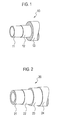
Fig. 1] Fig. 1 is a perspective view of a fuel hose according to an embodiment of the present invention. - [
Fig. 2] Fig. 2 is a perspective view of a fuel hose according to another embodiment of the present invention. - The following are descriptions of fuel hoses according to embodiments of the present invention. It is noted that "%" represents a percentage by mass, unless otherwise specified.
- A
fuel hose 10 according to an embodiment of the present invention shown inFig. 1 is used as a fuel vapor hose for vehicles using an alcohol blended fuel, for instance. Thefuel hose 10 has a laminated layer structure including anintermediate layer 12 containing polyvinyl alcohol (PVOH) and/or an ethylene-vinylalcohol (EVOH) copolymer, aninner layer 11 disposed on an inner periphery of theintermediate layer 12, and anouter layer 13 disposed on an outer periphery of theintermediate layer 12 and containing a rubber. Theinner layer 11 contains a first component containing nitrile rubber (NBR), and has cross-linked chains formed of carbon-carbon single bond. Theinner layer 11 is directly laminated to theintermediate layer 12. Theinner layer 11 is an innermost layer of the laminated layer structure constituting thefuel hose 10, and serves as a contact layer for a fuel to be transferred through thefuel hose 10. - The
fuel hose 10 includes theintermediate layer 12 containing PVOH and/or the EVOH copolymer that has excellent barrier properties to alcohol blended fuels and excellent adhesiveness to a rubber as described above. Therefore, thefuel hose 10 can be thinner in wall thickness than conventional hoses using a thick fluororesin, while having a barrier property that is equivalent to the conventional hoses. Due to a thinner wall thickness, thefuel hose 10 can ensure flexibility and workability. - The
inner layer 11 contains a vulcanized rubber that is composed mainly of NBR having cross-linked chains formed of carbon-carbon single bond. Therefore, theinner layer 11 can be directly laminated to theintermediate layer 12 without intervenient layers of different components therebetween. In the present invention, the condition that "theinner layer 11 is directly laminated to theintermediate layer 12" represents the condition that theinner layer 11 and theintermediate layer 12 are directly contacted to adhere to each other without intervenient layers of different components from theintermediate layer 12 such as an adhesive layer between theinner layer 11 and theintermediate layer 12. "The rubber composed mainly of NBR" represents a rubber containing 50% or more of NBR. NBR is preferably a medium-high nitrile rubber containing 31 % by mass or more of acrylonitrile (AN). When AN is less than 31 % by mass, there is a tendency to increase fuel permeability through an end of a fuel hose. Namely, it may be difficult to ensure fuel permeability. - A method for vulcanization of the
inner layer 11 includes peroxide vulcanization to provide a cross-linked substance composed of cross-linked chains formed of carbon-carbon single bond (C-C), using a cross-linking agent such as dicumyl peroxide (DCP) in view of adhesiveness to theintermediate layer 12. By directly laminating a rubber composed mainly of NBR to theintermediate layer 12 of PVOH and/or the EVOH copolymer or a resin composed mainly of a blended substance of those, followed by peroxide vulcanization, thefuel hose 10 can ensure an enhanced interlayer adhesion and an excellent barrier property to alcohol blended fuels. Due to the secure interlayer adhesion, thefuel hose 10 is not required to add adhesive components to an inner rubber of theintermediate layer 12, or apply an adhesive agent to a surface of a resin layer. Accordingly, thefuel hose 10 has an excellent fuel barrier property, an enhanced adhesiveness, and excellent workability. - The above-mentioned method can suppress extraction of adhesive components to fuels since the method is not required to use an adhesive agent or the like. In addition, the method is not required to have intervenient layers containing adhesive components between the
intermediate layer 12 and theinner layer 11. Thus, the entire wall thickness of the fuel hose can be reduced. Accordingly, a fuel hose is provided with excellent flexibility. - The
inner layer 11 preferably further contains, in addition to NBR as the first component, one or more second components selected from the group consisting of polyvinyl chloride (PVC), ethylene-acrylic rubber (AEM), ethylene-propylene rubber (EPM), and ethylene-propylene-diene rubber (EPDM). Namely, in addition to NBR used alone, theinner layer 11 contains an arbitrary mixture of NBR and a second component, such as a blended rubber of NBR and PVC, a blended rubber of NBR and EPDM, a blended rubber of NBR and EPM, a blended rubber of NBR and AEM, and a blended rubber of NBR, PVC and AEM. - The proportion of the second components to the
inner layer 11 is preferably 40% by mass or less when using PVC, and preferably 5% by mass to 30% by mass when using AEM, EPM and EPDM. When the proportion of PVC exceeds 40% by mass, flexibility of theinner layer 11 may be reduced. When the proportion of AEM, EPM and EPDM exceeds 30% by mass, there is a tendency to increase fuel permeability through an end of the fuel hose. Accordingly, it may be difficult to ensure fuel permeability. When the proportion of AEM, EPM and EPDM is less than 5% by mass, there is a tendency to decrease the adhesion to theintermediate layer 12. Accordingly, it may be difficult to ensure the interlayer adhesion. It is noted that the proportion of the second components represents a mass ratio of the second components to the total mass of theinner layer 11. - "The resin composed mainly of PVOH and/or the EVOH copolymer" composing the
intermediate layer 12 is a resin containing 70% by mass or more of those components. Such a resin has an excellent barrier property to alcohol blended fuels (anti-fuel-permeability, for example) and has excellent adhesiveness to a rubber. In order to ensure a barrier property of theintermediate layer 12, a copolymerization ratio of the ethylene-vinylalcohol copolymer is preferably within a range of ethylene:vinylalcohol = 20:80 to 38:62 in molar ratio. When using a mixture of polyvinyl alcohol and the ethylene-vinylalcohol copolymer, namely a blended resin, a blend ratio of those is preferably between 0:100 and 30:70. - The
fuel hose 10 suppresses extraction of adhesive components to fuels as described above. As an index of extraction, there is the following one. First, a liquid of isooctane, toluene and ethanol, which are mixed by ratios of 45:45:10 by volume, is sealed inside theinner layer 11, and left at a temperature of 40 °C for 168 hours (one week), whereby an extract from thefuel hose 10 is obtained. The total amount of respective components of a phenol compound, an epoxy compound, an acrylic compound, an isocyanate compound, a silane coupling agent and an osmium compound in hexane insoluble materials contained in the obtained extract is 0.5 mg/cm2 or less in mass conversion per area of an inside surface of the inner layer. Those compounds contained in the hexane insoluble materials of the extract may be compounds contained as adhesive components for adhesion between theinner layer 11 and theintermediate layer 12. If the total amount of those compounds exceeds 0.5 mg/cm2 in mass conversion per unit area in contact with the sealed liquid, peripheral parts may be deteriorated or their performances may be influenced. Thefuel hose 10 according to the embodiment of the present invention includes no adhesive component for adhesion between theinner layer 11 and theintermediate layer 12. Thus, the total amount of the above compounds falls within the range of 0.5 mg/cm2 or less in mass conversion per area of the inside surface of theinner layer 11. - The
outer layer 13 disposed on an outer periphery of theintermediate layer 12 may have a rubber material containing NBR, and one or more rubber components selected from the group consisting of a blended rubber of NBR and PVC, AEM, EPM, and EPDM. When using a rubber material containing those components for theouter layer 13, theouter layer 13 and theintermediate layer 12 may be directly laminated for vulcanization. Due to such a rubber material, an enhanced interlayer adhesion can be ensured without using specific adhesive components. In this case, an excellent fuel barrier property can be ensured not only for conduction of an alcohol blended fuel in contact with theinner layer 11, but also for conduction of an alcohol blended fuel in contact with theouter layer 13, and even for conduction of an alcohol blended fuel in contact with both theinner layer 11 and theouter layer 13. Vulcanization is preferably peroxide vulcanization similar to theinner layer 11. Both theinner layer 11 andouter layer 13 are thus preferably laminated directly on theintermediate layer 12. - The
fuel hose 10 basically has a three-layer structure composed of theintermediate layer 12, and theinner layer 11 and theouter layer 13 disposed inside and outside thereof. The number of layers is, however, not restrictive as long as theintermediate layer 12 and theinner layer 11 are directly laminated to each other by a peroxide vulcanization adhesion. In other words, thefuel hose 10 may have additional layers such as a cover layer inside theinner layer 11, or may have a secondouter layer 24 as a cover layer disposed outside an outer layer 23 as shown inFig. 2 depending on required performances. Each of theinner layer 11, theintermediate layer 12 and theouter layer 13 may have a multi-layer structure. There may be intervenient layers between theintermediate layer 12 and theouter layer 13. - The
fuel hose 10 is characterized by a combination of compositions of theinner layer 11 and theintermediate layer 12, and its method of production is not restricted. For example, thefuel hose 10 may be manufactured by production of a tubular hose with a multi-layer structure. The tubular hose is produced by a tandem extrusion process by multi-layer extrusion of respective layers or by a method of winding a resin to be positioned as an intermediate layer on an inner layer composed of a tubular rubber, followed by peroxide vulcanization. A vulcanization temperature may preferably be controlled within a range of 150 to 165 °C, more preferably within a range of 155 to 165 °C. A vulcanization time may preferably be within a range of 60 to 90 minutes. In some cases, a primary vulcanization may be followed by a secondary vulcanization. - The
fuel hose 10 according to the embodiment of the present invention has a configuration composed of theintermediate layer 12 containing PVOH and/or an EVOH copolymer with an excellent barrier property to alcohol blended fuels, and theinner layer 11 containing a rubber and disposed inside theintermediate layer 12. Thefuel hose 10 is thus suitable for vehicles using alcohol blended fuels, or suitable as a vapor hose for vehicular fuel systems. Thefuel hose 10 is widely applicable for various purposes other than hoses. For example, thefuel hose 10 can be applied to a container (multi-layer container) for various alcohol-containing liquids, a supply pipe, and a storage tank. A fuel circulated through a fuel hose according to the embodiment of the present invention or stored in a multi-layer container includes gasoline, diesel fuel, alcohol, LP gas, natural gas, hydrogen and a mixture of any of those. However, the fuel is not limited to the above-mentioned ones. - Specific examples will be described according to the embodiments of the present invention. The present invention is, however, not limited to these examples.
- A
fuel hose 10 with a three-layer structure illustrated inFig. 1 , including NBR as an inner layer 11 (acrylonitrile amount = 40%, vulcanizing system: peroxide vulcanization), EVOH (F101 manufactured by KURARAY CO., LTD., ethylene:vinylalcohol = 32:68) as anintermediate layer 12, and a blended rubber of NBR:PVC = 60:40 (vulcanizing system: peroxide vulcanization) as anouter layer 13, was manufactured in Example 1. Theinner layer 11, theintermediate layer 12, and theouter layer 13 were extruded under the condition of a cylinder temperature of 80 °C and a die temperature of 90 °C to obtain a tubular hose, followed by vulcanizing for 40 minutes at 150 °C. - The fuel hose obtained in Example 1 had an inner layer thickness of 0.5 mm, an intermediate layer thickness of 0.1 mm, and an outer layer thickness of 3.4 mm, with a hose outside diameter of 32.4 mm, a hose inside diameter of 24.4 mm, and a hose length of 300 mm.
- A three-layer structure identical to Example 1 was employed to obtain a fuel hose of Example 2, except for the
inner layer 11 and theouter layer 13 composed of a blended rubber of NBR:PVC = 60:40 (vulcanizing system: peroxide vulcanization). - A three-layer structure identical to Example 1 was employed to obtain a fuel hose of Example 3, except for the
inner layer 11 and theouter layer 13 composed of a blended rubber of NBR:PVC = 60:40 (vulcanizing system: peroxide vulcanization). - A three-layer structure identical to Example 1 was employed to obtain a fuel hose of Example 4, except for the
inner layer 11 and theouter layer 13 composed of a blended rubber of NBR:EPM = 60:40 (vulcanizing system: peroxide vulcanization). - A three-layer structure identical to Example 1 was employed to obtain a fuel hose of Example 5, except for the
intermediate layer 12 composed of an EVOH copolymer resin of ethylene:vinylalcohol = 24:76. - A three-layer structure identical to Example 5 was employed to obtain a fuel hose of Example 6, except for the
inner layer 11 and theouter layer 13 composed of a blended rubber of NBR:PVC = 60:40 (vulcanizing system: peroxide vulcanization). - A three-layer structure identical to Example 5 was employed to obtain a fuel hose of Example 7, except for the
inner layer 11 and theouter layer 13 composed of a blended rubber of NBR:EPDM = 60:40 (vulcanizing system: peroxide vulcanization). - A three-layer structure identical to Example 5 was employed to obtain a fuel hose of Example 8, except for the
inner layer 11 and theouter layer 13 composed of a blended rubber of NBR:EPM = 60:40 (vulcanizing system: peroxide vulcanization). - A three-layer structure identical to Example 1 was employed to obtain a fuel hose of Example 9, except for the
intermediate layer 12 composed of PVOH. - A three-layer structure identical to Example 9 was employed to obtain a fuel hose of Example 10, except for the
inner layer 11 and theouter layer 13 composed of a blended rubber of NBR:PVC = 60:40 (vulcanizing system: peroxide vulcanization). - A three-layer structure identical to Example 9 was employed to obtain a fuel hose of Example 11, except for the
inner layer 11 and theouter layer 13 composed of a blended rubber of NBR:EPDM = 60:40 (vulcanizing system: peroxide vulcanization). - A three-layer structure identical to Example 9 was employed to obtain a fuel hose of Example 12, except for the
inner layer 11 and theouter layer 13 composed of a blended rubber of NBR:EPM = 60:40 (vulcanizing system: peroxide vulcanization). - A three-layer structure identical to Example 1 was employed to obtain a fuel hose of Example 13, except for the
outer layer 13 composed of ECO. - A three-layer structure identical to Example 1 was employed to obtain a fuel hose of Example 14, except for the
inner layer 11 and theouter layer 13 composed of a blended rubber of NBR:PVC:AEM = 50:20:30 (vulcanizing system: peroxide vulcanization). - A three-layer structure identical to Example 1 was employed to obtain a fuel hose of Example 15, except for the
inner layer 11 and theouter layer 13 composed of a blended rubber of NBR:AEM = 95:5 (vulcanizing system: peroxide vulcanization). - A three-layer structure identical to Example 1 was employed to obtain a fuel hose of Example 16, except for the
inner layer 11 and theouter layer 13 composed of a blended rubber of NBR:PVC:EPDM = 67:28:5 (vulcanizing system: peroxide vulcanization). - A three-layer structure identical to Example 1 was employed to obtain a fuel hose of Example 17, except for the
inner layer 11 and theouter layer 13 composed of a blended rubber of NBR:PVC:EPDM = 50:20:30 (vulcanizing system: peroxide vulcanization). - A multi-layer fuel hose with a four-layer structure illustrated in
Fig. 2 was employed in Example 18. This example included an inner layer 21 and an outer layer 23 composed of a blended rubber of NBR:EPDM = 70:30 (vulcanizing system: peroxide vulcanization), and an intermediate layer 22 composed of EVOH (F101 manufactured by KURARAY CO., LTD., ethylene:vinylalcohol = 32:68), which were prepared by a method identical to Example 1, in addition to a secondouter layer 24 composed of CSM and disposed outside the outer layer 23, so as to obtain the fuel hose in this example. - The fuel hose obtained in Example 18 had an inner layer thickness of 1.5 mm, an intermediate layer thickness of 0.1 mm, an outer layer thickness of 1.9 mm, and a second outer layer thickness of 0.5 mm, with a hose outside diameter of 32.4 mm, a hose inside diameter of 24.4 mm, and a hose length of 300 mm.
- A three-layer structure identical to Example 14 was employed to obtain a fuel hose of Example 19, except for the
intermediate layer 12 composed of an EVOH copolymer resin of ethylene:vinylalcohol = 24:76. - A three-layer structure identical to Example 15 was employed to obtain a fuel hose of Example 20, except for the
intermediate layer 12 composed of an EVOH copolymer resin of ethylene:vinylalcohol = 24:76. - A three-layer structure identical to Example 16 was employed to obtain a fuel hose of Example 21, except for the
intermediate layer 12 composed of an EVOH copolymer resin of ethylene:vinylalcohol = 24:76. - A three-layer structure identical to Example 17 was employed to obtain a fuel hose of Example 22, except for the
intermediate layer 12 composed of an EVOH copolymer resin of ethylene:vinylalcohol = 24:76. - A four-layer structure identical to Example 18 was employed to obtain a fuel hose of Example 23, except for the
intermediate layer 12 composed of an EVOH copolymer resin of ethylene:vinylalcohol = 24:76. - A three-layer structure identical to Example 14 was employed to obtain a fuel hose of Example 24, except for the
intermediate layer 12 composed of PVOH. - A three-layer structure identical to Example 15 was employed to obtain a fuel hose of Example 25, except for the
intermediate layer 12 composed of PVOH. - A three-layer structure identical to Example 16 was employed to obtain a fuel hose of Example 26, except for the
intermediate layer 12 composed of PVOH. - A three-layer structure identical to Example 17 was employed to obtain a fuel hose of Example 27, except for the
intermediate layer 12 composed of PVOH. - A four-layer structure identical to Example 18 was employed to obtain a fuel hose of Example 28, except for the
intermediate layer 12 composed of PVOH. - A fuel hose with a four-layer structure including an intervenient layer intervening between an intermediate layer and an outer layer was employed in Comparative Example 1. This example included an inner layer composed of NBR (vulcanizing system: peroxide vulcanization), the intermediate layer composed of a ternary copolymer fluororesin THV, and the outer layer composed of CSM, which were prepared by a method identical to Example 1, in addition to the intervenient layer between the outer layer and the intermediate layer composed of NBR identical to the inner layer, so as to obtain the fuel hose in this example.
- The fuel hose obtained in Comparative Example 1 had an inner layer thickness of 1.5 mm, an intermediate layer thickness of 0.1 mm, an intervenient layer thickness of 1.9 mm, and an outer layer thickness of 0.5 mm, with a hose outside diameter of 32.4 mm, a hose inside diameter of 24.4 mm, and a hose length of 300 mm.
- A four-layer structure identical to Comparative Example 1 was employed to obtain a fuel hose of Comparative Example 2, except for the inner layer and the outer layer composed of NBR (acrylonitrile amount = 40%, vulcanizing system: sulfur vulcanization) with an addition of 1, 5-diazabicyclo[4.3.0]-nonene-5 as an adhesive component for adhesion to the intermediate layer, and the intermediate layer composed of a ternary copolymer fluororesin THV.
- The fuel hose obtained in Comparative Example 2 had an inner layer thickness of 1.5 mm, an intermediate layer thickness of 0.1 mm, an outer layer thickness of 1.9 mm, and a second outer layer thickness of 0.5 mm, with a hose outside diameter of 32.4 mm, a hose inside diameter of 24.4 mm, and a hose length of 300 mm.
- A four-layer structure identical to Comparative Example 2 was employed to obtain a fuel hose of Comparative Example 3, except for the inner layer and the outer composed of NBR with the acrylonitrile amount of 30%.
- The respective fuel hoses obtained in the foregoing examples and comparative examples were subjected to a fuel permeability test, an adhesion test and a fuel extraction test, and performances of those fuel hoses were evaluated. The results thereof are listed in Tables 1 and 2.
- A mixed fuel of commercially available regular gasoline (90 vol %) and ethanol (10 vol %) was poured in a stainless steel test container, where each fuel hose obtained in the examples and comparative examples was fixed at one end thereof by a clamp, while the other end was fixed by a clamp to a stainless steel sealing plug. Under this condition, each fuel hose was left in an atmosphere of 40 °C for 20 weeks. Thereafter, a fuel permeation rate was measured using SHED (Sealed Housing For Evaporative Determination) under specified conditions of CARB (California Air Resources Board).
- In Tables 1 and 2, "double circle ⊚)" denotes a permeation rate smaller than one tenth of that of the multi-layer hose of Comparative Example 1, and "single circle (○)" denotes an equivalent permeation rate to the multi-layer hose of Comparative Example 1.
- A mixed fuel of commercially available regular gasoline (90 vol %) and ethanol (10 vol %) was sealed in each fuel hose of the examples and comparative examples, which was left at 60 °C for 168 hours. After removal of sealed liquid, each fuel hose was left at room temperature for 10 minutes. Then, test pieces were punched out from the respective fuel hoses so that each test piece had a size of 10 mm width by 200 mm length, and a thickness of the fuel hose itself.
- A part of the intermediate layer was peeled from a part of an inner rubber layer (as the inner layer) in contact with the intermediate layer at an arbitrary location of each punched test piece to some extent, and held by a grip of a tester. The tester was operated under prescribed conditions in JIS K6256, describing a tensile load curve on a graph. An average value of wavy sections in the graph was determined as an exfoliation load, and exfoliation strength was calculated, such that:
- Exfoliation strength (N/cm) = Exfoliation load (N) / Test piece width (cm) In Tables 1 and 2, "double circle (⊚)" denotes an exfoliation strength greater than that of the multi-layer hose of Comparative Example 1, and "single circle (O)" denotes an equivalent strength to the multi-layer hose of Comparative Example 1.
- A mixed fuel of isooctane (45 vol %), toluene (45 vol %), and ethanol (10 vol %) was sealed in each fuel hose of the examples and comparative examples, which was left at 40 °C for 168 hours. Thereafter, sealed liquid was removed as an extract. The extract was dried and concentrated by exposure to blown air. The concentrated liquid was mixed with hexane, which was stirred for one hour or more by an ultrasonic cleaner.
- After the mixed liquid was left for 24 hours, supernatant liquid was removed, and precipitates were vacuum-dried at 40 °C for 8 hours. Insoluble substances thus obtained were taken as hexane insoluble materials.
- The total amount of a phenol compound, an epoxy compound, an acrylic compound, an isocyanate compound, a silane coupling agent, and an osmium compound in the hexane insoluble materials were measured by use of analyzers such as a gas chromatography-mass spectrometer (GC-MS) and an infrared spectroscopy (IR). Then, the total amount of the above components was calculated in mass conversion (mg/cm2) per area of an inside surface of the multi-layer hose. In Tables 1 and 2, "single circle (O)" denotes the total amount within a range of 0.5 mg/cm2 or less, and "triangle (Δ)" denotes the total amount exceeding 0.5 mg/cm2.
[Table 1] Section Hose Structure Hose Property Inner Layer Intermediate Layer Intervenient Layer Outer Layer Second Outer Layer Fuel Permeability Adhesiveness Fuel Extraction Total Evaluation Example 1 NBR EVOH (Copolymerization Ratio = 32:68) - NBR + PVC - ⊚ ⊚ ○ ⊚ Example 2 NBR + PVC EVOH (Copolymerization Ratio = 32:68) - NBR + PVC - ⊚ ⊚ ○ ⊚ Example 3 NBR + EPDM EVOH (Copolymerization Ratio = 32:68) - NBR + EPDM - ⊚ ⊚ ○ ⊚ Example 4 NBR + EPM EVOH (Copolymerizalion Ratio = 32:68) - NBR + EPM - ⊚ ⊚ ○ ⊚ Example 5 NBR EVOH (Copolymerization Ratio = 24:76) - NBR + PVC - ⊚ ⊚ ○ ⊚ Example 6 NBR + PVC EVOH (Copolymerization Ratio = 24:76) - NBR +PVC - ⊚ ⊚ ○ ⊚ Example 7 NBR + EPDM EVOH (Copolymerizalion Ratio = 24:76) - NBR + EPDM - ⊚ ⊚ ○ ⊚ Example 8 NBR + EPM EVOH (Copolymerization Ratio = 24:76) - NBR + EPM - ⊚ ⊚ ○ ⊚ Example 9 NBR PVOH - NBR + PVC - ⊚ ⊚ ○ ⊚ Example 10 NBR + PVC PVOH - NBR +PVC - ⊚ ⊚ ○ ⊚ Example 11 NBR + EPDM PVOH - NBR + EPDM - ⊚ ⊚ ○ ⊚ Example 12 NBR + EPM PVOH - NBR + EPM - ⊚ ⊚ ○ ⊚ Example 13 NBR EVOH (Copolymerization Ratio =32:68) - ECO - ⊚ ⊚ ○ ⊚ Comparative Example 1 NBR THV NBR CSM - O ○ Δ ○ Comparative Example 2 NBR THV NBR CSM - O ○ Δ ○ Comparative Example 3 NBR THV NBR CSM - O ○ Δ ○ [Table 2] Section Hose Structure Hose Property Inner Layer Intermediate Layer Intervenient Layer Outer Layer Second Outer Layer Fuel Permeability Adhesiveness Fuel Extraction Total Evaluation Example 14 NBR +PVC +AEM, EVOH (Copolymerization Ratio =32:68) - NBR +PVC +AEM - ⊚ ⊚ ○ ⊚ Example 15 NBR +AEM EVOH (Copolymerization Ratio = 32:68) - NBR +AEM - ⊚ ⊚ ○ ⊚ Example 16 NBR +PVC +EPDM EVOH (Copolymerization Ratio =32:68) - NBR +PVC + EPDM - ⊚ ⊚ ○ ⊚ Example 17 NBR +PVC +EPDM EVOH (Copolymerization Ratio =32:68) - NBR +PVC + EPDM - ⊚ ⊚ ○ ⊚ Example 18 NBR +EPDM EVOH (Copolymerization Ratio =32:68) - NBR + EPDM CSM ⊚ ⊚ ○ ⊚ Example 19 NBR +PVC +AEM EVOH (Copolymerization Ratio =24:76) - NBR +PVC +AEM - ⊚ ⊚ ○ ⊚ Example 20 NBR +AEM EVOH (Copolymerization Ratio =24:76) - NBR +AEM, - ⊚ ⊚ ○ ⊚ Examples 21 NBR +PVC +EPDM EVOH (Copolymerization Ratio =24:76) - NBR +PVC + EPDM - ⊚ ⊚ ○ ⊚ Example 22 NBR +PVC +EPDM EVOH (Copolymerization Ratio =24:76) - NBR +PVC + EPDM - ⊚ ⊚ ○ ⓞ Example 23 NBR +EPDM EVOH (Copolymerization Ratio =24:76) - NBR + EPDM CSM ⊚ ⊚ ○ ⓞ Example 24 NBR +PVC +AEM PVOH - NBR +PVC + AEM - ⊚ ⊚ ○ ⊚ Example 25 NBR + AEM PVOH - NBR + AEM - ⊚ ⊚ ○ ⓞ Example 26 NBR +PVC + EPDM PVOH - NBR +PVC + EPDM - ⊚ ⊚ ○ ⓞ Example 27 NBR +PVC +EPDM PVOH - NBR +PVC + EPDM - ⊚ ⊚ ○ ⓞ Example 28 NBR +EPDM PVOH - NBR + EPDM CSM ⊚ ⊚ ○ ⓞ - As shown in Tables 1 and 2, it was verified that all the fuel hoses in Examples 1 to 28 had superior properties compared to the fuel hoses in the comparative examples. It was verified that the respective fuel hoses in Examples 1 to 28 had a sufficient interlayer adhesion property between the inner layer of a rubber and the intermediate layer as a fuel barrier layer. Moreover, due to a vulcanized adhesion between the inner layer and the intermediate layer, and no adhesive component in the layers, a small amount of fuel extraction was observed in any fuel extraction test, and good results were obtained in the examples. Namely, the fuel hoses in Examples 1 to 28 had an excellent adhesive property due to the intermediate layer of a resin composed mainly of PVOH and/or the EVOH copolymer, and the rubber layers having prescribed components disposed inside and outside the intermediate layer. Further, the respective fuel hoses in Examples 1 to 28 had a sufficient interlayer adhesion property between the inner layer of a rubber and the intermediate layer (fuel barrier layer) compared with the comparative examples using the intermediate layer composed of fluororesin and the inner layer and the outer layer composed of NBR. It was verified that the fuel hoses in Examples 1 to 28 had a small amount of fuel extraction because of no adhesive component in the layers, and had excellent fuel permeation against ethanol blended gasoline.
- Although the invention has been described, the invention is not limited to the foregoing embodiments, and modifications may become apparent to those skilled in the art within the scope of the invention.
- For example, in the case of a multi-layer hose in which fuels are in direct contact not with an inner layer but with an outer layer of the multi-layer hose, the above-described configuration (for example, the acrylonitrile content in NBR as a constituent is 31 % by mass or more) may be employed as a preferred configuration of the outer layer similarly to the preferred configuration of the inner layer.
- The entire contents of Japanese Patent Application No.
P2008-133020 P2008-133022 P2009-119967 -
- 10, 20
- Fuel hose
- 11, 21
- Inner layer
- 12, 22
- Intermediate layer
- 13, 23
- Outer layer
- 24
- Second outer layer
Claims (4)
- A fuel hose comprising:a laminated layer structure including:an intermediate layer containing polyvinyl alcohol and/or an ethylene-vinylalcohol copolymer;an inner layer disposed on an inner periphery of the intermediate layer; andan outer layer disposed on an outer periphery of the intermediate layer and containing a rubber,wherein the inner layer comprises: a first component containing nitrile rubber; and cross-linked chains formed of carbon-carbon single bond, and is directly laminated to the intermediate layer.
- The fuel hose according to claim 1, wherein the inner layer further comprises one or more second components selected from the group consisting of polyvinyl chloride, ethylene-acrylic rubber, ethylene-propylene rubber, and ethylene-propylene-diene rubber.
- The fuel hose according to claim 1 or 2, wherein an extract from the fuel hose is obtained by the method in which a liquid of isooctane, toluene and ethanol, which are mixed by ratios of 45:45:10 by volume, is sealed inside the inner layer, and left at a temperature of 40 °C for 168 hours, and
a total amount of respective components of a phenol compound, an epoxy compound, an acrylic compound, an isocyanate compound, a silane coupling agent and an osmium compound in hexane insoluble materials contained in the obtained extract is 0.5 mg/cm2 or less in mass conversion per area of an inside surface of the inner layer. - The fuel hose according to any one of claims 1 to 3, wherein the outer layer comprises: nitrile rubber; and one or more rubber components selected from the group consisting of a blended rubber of nitrile rubber and polyvinyl chloride, ethylene-acrylic rubber, ethylene-propylene rubber, and ethylene-propylene-diene rubber.
Applications Claiming Priority (4)
| Application Number | Priority Date | Filing Date | Title |
|---|---|---|---|
| JP2008133022 | 2008-05-21 | ||
| JP2008133020 | 2008-05-21 | ||
| JP2009119967A JP5604807B2 (en) | 2008-05-21 | 2009-05-18 | Fuel hose |
| PCT/JP2009/059270 WO2009142241A1 (en) | 2008-05-21 | 2009-05-20 | Fuel hose |
Publications (2)
| Publication Number | Publication Date |
|---|---|
| EP2279858A1 true EP2279858A1 (en) | 2011-02-02 |
| EP2279858A4 EP2279858A4 (en) | 2011-05-04 |
Family
ID=41340167
Family Applications (1)
| Application Number | Title | Priority Date | Filing Date |
|---|---|---|---|
| EP09750603A Withdrawn EP2279858A4 (en) | 2008-05-21 | 2009-05-20 | Fuel hose |
Country Status (4)
| Country | Link |
|---|---|
| US (1) | US8530013B2 (en) |
| EP (1) | EP2279858A4 (en) |
| JP (1) | JP5604807B2 (en) |
| WO (1) | WO2009142241A1 (en) |
Cited By (1)
| Publication number | Priority date | Publication date | Assignee | Title |
|---|---|---|---|---|
| EP3766699A4 (en) * | 2018-03-16 | 2021-12-15 | Mitsui Chemicals, Inc. | LAMINATE CONSISTING OF THE COMPOSITION OF THE ETHYLENE / ALPHA-OLEFIN / NONCONJUGATE POLYENE COPOLYMER, AND THE COMPOSITION OF THE ALPHA / ALPHA-OLEFIN / NONCONJUGATE POLYENE COPOLYMER |
Families Citing this family (4)
| Publication number | Priority date | Publication date | Assignee | Title |
|---|---|---|---|---|
| JP5604807B2 (en) * | 2008-05-21 | 2014-10-15 | 日産自動車株式会社 | Fuel hose |
| US10240697B2 (en) | 2014-08-22 | 2019-03-26 | 5elem Material Scientific(Jiangsu) Co., LTD. | Fracturing liquid delivery hose for recovery of shale oil and gas, and manufacturing method thereof |
| US10458576B2 (en) * | 2016-10-13 | 2019-10-29 | Teknor Apex Company | Hose assembly with modified thermoplastic inner tube |
| KR102787431B1 (en) * | 2022-10-18 | 2025-04-01 | 주식회사 세종플렉스 | Hoses made of PVC and rubber |
Family Cites Families (27)
| Publication number | Priority date | Publication date | Assignee | Title |
|---|---|---|---|---|
| CH548933A (en) * | 1972-03-13 | 1974-05-15 | Bobst Fils Sa J | INSTALLATION FOR OBTAINING A READING WINDOW FOR THE RECORDING OF AN OPERATION IN A PRINTING OR CARDBOARDING MACHINE. |
| US4043958A (en) * | 1974-10-17 | 1977-08-23 | Uniroyal, Inc. | Flame retarded NBR/PVC compositions |
| DE4223984A1 (en) | 1992-07-21 | 1994-01-27 | Continental Ag | Thermoplastic elastomer and its bond to a reinforcement |
| US5427831B1 (en) * | 1993-11-12 | 1998-01-06 | Du Pont | Fluoropolymer laminates |
| US5679425A (en) * | 1994-11-23 | 1997-10-21 | Plumley Companies, Inc. | Hose for fuel handling systems |
| JP3905225B2 (en) * | 1998-06-29 | 2007-04-18 | 東海ゴム工業株式会社 | Carbon dioxide refrigerant transport hose |
| US6333386B1 (en) * | 1999-06-28 | 2001-12-25 | Tokai Rubber Industries, Ltd. | Rubber composition, hose of low fuel permeation, and electroconductive hose of low fuel permeation |
| US6340511B1 (en) * | 1999-10-27 | 2002-01-22 | Tokai Rubber Industries, Ltd. | Fuel hose |
| JP2001131347A (en) * | 1999-11-08 | 2001-05-15 | Tokai Rubber Ind Ltd | Rubber composition and automotive fuel transfer hose |
| JP4604310B2 (en) * | 2000-05-11 | 2011-01-05 | 東海ゴム工業株式会社 | Manufacturing method of fuel transport hose |
| AU2001225857A1 (en) | 2000-08-23 | 2002-03-04 | Dyneon Llc | Process for preparing a multi-layer article having a fluoroplastic layer and an elastomer layer |
| US6773755B2 (en) | 2001-08-08 | 2004-08-10 | 3M Innovative Properties Company | Process for preparing a multi-layer article having a fluoroplastic layer and an elastomer layer |
| JP2003074761A (en) * | 2001-09-06 | 2003-03-12 | Tokai Rubber Ind Ltd | Metal impermeable membrane and impermeable hose |
| JP2004176908A (en) * | 2002-10-03 | 2004-06-24 | Bridgestone Corp | Low gas-permeability hose |
| JP4603819B2 (en) * | 2003-08-05 | 2010-12-22 | 株式会社ブリヂストン | Vulcanized adhesive body of rubber and resin member and method for producing the same |
| JP2005249086A (en) * | 2004-03-04 | 2005-09-15 | Togawa Rubber Co Ltd | Multi-layer hose |
| EP1931199A4 (en) * | 2005-08-31 | 2009-07-29 | Univ Tennessee Res Foundation | TREATMENT OF RENAL DISEASE, BURNS, INJURIES OR SPINAL CORD INJURY USING ANDROGEN RECEPTOR SELECTIVE MODULATORS |
| JP2007269862A (en) * | 2006-03-30 | 2007-10-18 | Toyoda Gosei Co Ltd | Rubber composition and rubber hose for fuel system |
| JP5197615B2 (en) * | 2006-11-01 | 2013-05-15 | アーケマ・インコーポレイテッド | Fluid transfer multilayer tube based on polyamide and ethyl vinyl alcohol or polyvinyl alcohol |
| JP4857093B2 (en) | 2006-11-29 | 2012-01-18 | 日本ポリプロ株式会社 | Deep drawn container |
| JP4915222B2 (en) | 2006-11-29 | 2012-04-11 | パナソニック株式会社 | Packing apparatus and processing method using the apparatus |
| EP1975196B1 (en) * | 2007-03-27 | 2009-11-25 | Tokai Rubber Industries, Ltd. | Hydrin rubber composition and heat-resistant hose using the same as material |
| US20090123683A1 (en) | 2007-11-09 | 2009-05-14 | Miller Lance D | Low-Permeation Flexible Fuel Hose |
| JP5015730B2 (en) | 2007-11-13 | 2012-08-29 | 株式会社ブリヂストン | Pneumatic tires for motorcycles |
| JP5604807B2 (en) * | 2008-05-21 | 2014-10-15 | 日産自動車株式会社 | Fuel hose |
| EP2292428B1 (en) * | 2008-06-26 | 2012-07-04 | Unimatec Co., Ltd. | Rubber laminate |
| US20100021665A1 (en) * | 2008-07-24 | 2010-01-28 | Kenneth Scott Jackson | Vulcanized biofuel hose |
-
2009
- 2009-05-18 JP JP2009119967A patent/JP5604807B2/en not_active Expired - Fee Related
- 2009-05-20 US US12/993,195 patent/US8530013B2/en not_active Expired - Fee Related
- 2009-05-20 EP EP09750603A patent/EP2279858A4/en not_active Withdrawn
- 2009-05-20 WO PCT/JP2009/059270 patent/WO2009142241A1/en not_active Ceased
Cited By (1)
| Publication number | Priority date | Publication date | Assignee | Title |
|---|---|---|---|---|
| EP3766699A4 (en) * | 2018-03-16 | 2021-12-15 | Mitsui Chemicals, Inc. | LAMINATE CONSISTING OF THE COMPOSITION OF THE ETHYLENE / ALPHA-OLEFIN / NONCONJUGATE POLYENE COPOLYMER, AND THE COMPOSITION OF THE ALPHA / ALPHA-OLEFIN / NONCONJUGATE POLYENE COPOLYMER |
Also Published As
| Publication number | Publication date |
|---|---|
| JP5604807B2 (en) | 2014-10-15 |
| JP2010000787A (en) | 2010-01-07 |
| US8530013B2 (en) | 2013-09-10 |
| EP2279858A4 (en) | 2011-05-04 |
| US20110088804A1 (en) | 2011-04-21 |
| WO2009142241A1 (en) | 2009-11-26 |
Similar Documents
| Publication | Publication Date | Title |
|---|---|---|
| US7011114B2 (en) | Automotive fuel hose | |
| EP2212605A1 (en) | Low-permeation flexible fuel hose | |
| US8530013B2 (en) | Fuel hose | |
| US8356638B2 (en) | Multi-layer hose | |
| JP2007292303A (en) | Fuel transport hose | |
| JP5566573B2 (en) | Multilayer hose | |
| US20090000684A1 (en) | Multi-layer hose | |
| US6923218B2 (en) | Fuel hose and producing method therefor | |
| EP1577597A1 (en) | Resin tube | |
| US20060124190A1 (en) | Fluoropolymer - EVOH - modified PA tube | |
| JP3905225B2 (en) | Carbon dioxide refrigerant transport hose | |
| JP2008265283A (en) | Gasohol fuel hose | |
| EP1580473A1 (en) | Multilayer tube | |
| CN1822950A (en) | Nylon composite article and its preparation method | |
| US8757214B2 (en) | Multi-layer hose | |
| JP4896897B2 (en) | Gasohol fuel hose | |
| US20090169791A1 (en) | Multilayer article | |
| JP5289779B2 (en) | Gasohol fuel hose | |
| CN215111016U (en) | Fuel pipe that six hyposmosis of state discharged | |
| JP2009156397A (en) | Multilayer hose | |
| JP2006234125A (en) | Fuel system rubber hose | |
| JP2007175929A (en) | Fuel hose |
Legal Events
| Date | Code | Title | Description |
|---|---|---|---|
| PUAI | Public reference made under article 153(3) epc to a published international application that has entered the european phase |
Free format text: ORIGINAL CODE: 0009012 |
|
| 17P | Request for examination filed |
Effective date: 20101027 |
|
| AK | Designated contracting states |
Kind code of ref document: A1 Designated state(s): AT BE BG CH CY CZ DE DK EE ES FI FR GB GR HR HU IE IS IT LI LT LU LV MC MK MT NL NO PL PT RO SE SI SK TR |
|
| AX | Request for extension of the european patent |
Extension state: AL BA RS |
|
| A4 | Supplementary search report drawn up and despatched |
Effective date: 20110405 |
|
| RIC1 | Information provided on ipc code assigned before grant |
Ipc: B32B 1/08 20060101AFI20091211BHEP Ipc: C08L 9/02 20060101ALI20110328BHEP Ipc: F16L 11/04 20060101ALI20110328BHEP Ipc: B32B 25/08 20060101ALI20110328BHEP |
|
| DAX | Request for extension of the european patent (deleted) | ||
| 17Q | First examination report despatched |
Effective date: 20111111 |
|
| STAA | Information on the status of an ep patent application or granted ep patent |
Free format text: STATUS: THE APPLICATION IS DEEMED TO BE WITHDRAWN |
|
| 18D | Application deemed to be withdrawn |
Effective date: 20171201 |