EP2279654A2 - Spreader disk assembly convertible for windrowing - Google Patents
Spreader disk assembly convertible for windrowing Download PDFInfo
- Publication number
- EP2279654A2 EP2279654A2 EP10170743A EP10170743A EP2279654A2 EP 2279654 A2 EP2279654 A2 EP 2279654A2 EP 10170743 A EP10170743 A EP 10170743A EP 10170743 A EP10170743 A EP 10170743A EP 2279654 A2 EP2279654 A2 EP 2279654A2
- Authority
- EP
- European Patent Office
- Prior art keywords
- bat
- disk
- bats
- spreader
- disk assembly
- Prior art date
- Legal status (The legal status is an assumption and is not a legal conclusion. Google has not performed a legal analysis and makes no representation as to the accuracy of the status listed.)
- Granted
Links
Images




Classifications
-
- A—HUMAN NECESSITIES
- A01—AGRICULTURE; FORESTRY; ANIMAL HUSBANDRY; HUNTING; TRAPPING; FISHING
- A01D—HARVESTING; MOWING
- A01D41/00—Combines, i.e. harvesters or mowers combined with threshing devices
- A01D41/12—Details of combines
- A01D41/1243—Devices for laying-out or distributing the straw
-
- A—HUMAN NECESSITIES
- A01—AGRICULTURE; FORESTRY; ANIMAL HUSBANDRY; HUNTING; TRAPPING; FISHING
- A01F—PROCESSING OF HARVESTED PRODUCE; HAY OR STRAW PRESSES; DEVICES FOR STORING AGRICULTURAL OR HORTICULTURAL PRODUCE
- A01F29/00—Cutting apparatus specially adapted for cutting hay, straw or the like
- A01F29/09—Details
- A01F29/12—Discharge means
Definitions
- This invention relates to a spreader disk assembly for spreading crop residue such as straw discharged from an agricultural harvesting machine, and more particularly, which has bats quickly and easily convertible from a deployed spreading mode to a flattened stowed mode for windrowing.
- a harvesting machine such as, but not limited to, a combine
- a crop such as wheat or other grasses
- MOG threshing and separating system
- Much of this crop residue is propelled within the machine from the threshing and separating system to a discharge outlet, typically at the rear of the machine.
- a spreader will be provided, configured and operable for propelling the crop residue outwardly from the machine so as to be deposited in a desired pattern on the field.
- rear doors are configurable in a windrowing mode such that the discharged crop residue will bypass the spreader, so as to pass outwardly from another discharge outlet in a more compact flow, for forming a windrow on a field. It is also possible for the spreader to be removed for windrowing.
- both of these options for conversion to a windrowing mode, and conversion back to the spreading node entail a significant amount of work and time, which translates into lost harvesting productivity, and in the latter instance, the spreader must be lifted, carried and stored, which can be cumbersome, particularly, when such conversions are required multiple times during a harvesting operation, e.g., more than once daily.
- One common spreader configuration is a pair of circular spreader disk assemblies mounted side-by-side generally beneath the combine's rear crop residue discharge outlet.
- Such spreader disk assemblies typically have been assembled from various component parts, including a spreader disk or plate and a plurality of separate spreader fins or bats of varying configurations which have been installed on the spreader plates to extend upwardly from a top surface of the spreader plate.
- the spreader bats have typically been secured to the spreader disks by various hardware connectors, some of which allow mounting the bats in a variety of positions or orientations.
- the spreader disk assembly includes a disk having a substantially planar first surface, a second surface opposite the first surface, and a rotational axis extending through a central portion of the disk between the first and second surfaces, and a plurality of elongate bats disposed on the first surface at angularly spaced locations about the rotational axis, respectively, each of the bats having a longitudinal edge pivotally or hingedly mounted to the disk for pivotal or hinged movement of the bat between a deployed position extending generally axially outwardly from the first surface, and a stowed position extending generally parallel to the first surface.
- the assembly additionally includes bat support mechanisms extending through the disk and connected to the bats, respectively, each of the support mechanisms being configurable in a bat deploying mode for lockingly supporting and holding the bat connected thereto in the deployed position, and in a bat stowing mode holding the bat connected thereto in the stowed position.
- each of the bats is generally flat and will lay substantially flat against the first surface when in the stowed position.
- each of the bat support mechanisms comprises an elongate support bracket extending longitudinally through at least one slot through the disk and having a first end pivotally connected to the bat, and a second end located adjacent to the second surface, the bracket carrying a locking mechanism configurable in a first manner for supporting and holding the bat in the deployed position, and in a second manner for holding the bat in the stowed position.
- the locking mechanism comprises a detent element on the second surface and a resiliently elongatable strap having one end captured and carried in a slot or slots extending longitudinally along the bracket, e.g., in a T-shaped configuration the arms of which being receivable in spaced apart, parallel slots, so as to be movable longitudinally relative thereto, and an opposite end (leg of the T-shape) configured to be cooperatively engaged and held by the detent element, wherein the strap is movable to one end of the slot and engageable with the detent element for releasably holding the bat in the deployed position, and wherein the strap is movable to an opposite end of the slot and engageable with the detent element for releasably holding the bat in the stowed position, in an over center clamping action wherein the strap is held in tension.
- the spreader disk will be located below or in another suitable position in relation to a crop residue discharge outlet of a harvesting machine such as a combine, for receiving a flow of crop residue therefrom.
- a single disk can be used or multiple disks, e.g., commonly a pair of side-by-side disks counter rotatable by a suitable drive, such as, but not limited to, a conventional right angle bevel gear shaft drive, a belt drive, or motor drive, of well known construction.
- a disk can include any number of the bats, e.g., 3, 4, 6, as desired or required for a particular application.
- the bats are simply and easily convertible between the deployed and stowed modes, by releasing the strap from the detent element, moving or repositioning the bat and the strap, and re-engaging the strap with the detent element. No removal of the bats, or the disks, is required. And, if a large number of bats is used, some of the bats, e.g., alternating ones, can be selectably moved to the stowed position, for altering the spreading characteristics.
- the bats will operate conventionally to spread the crop residue discharged thereon in the well known manner.
- the bats will allow crop residue to flow thereover, while acting to decelerate and contain the flow to a width suitable for a windrow. And, the residue will be placed more gently onto the field stubble, so as to be more easily raked and picked up, and to allow better air circulation from below.
- Machine 20 is of conventional construction and operation, and includes harvesting apparatus operable for cutting crops as machine 20 moves forwardly over a field, as denoted by arrow F.
- Machine 20 also includes apparatus for conveying the cut crops into machine 20, then threshing and separating grain from the MOG, including crop residue, which when harvesting grasses such as wheat, typically includes a large quantity of straw.
- a spreader assembly 24 is mounted generally below discharge outlet 22, and is partially concealed by side sheets 26, as shown.
- Spreader assembly 24 shown includes a pair of side by side spreader disk assemblies 28, which are drivingly counter rotated by a suitable drive or drives, which here is depicted as a bevel gear shaft drive 30 contained within machine 20, and constructed and operable in the well known manner.
- each spreader disk assembly 28 is supported by a downwardly extending shaft 34 of drive 30 for rotation, as denoted by arrow R, about a central rotational axis 32, such that the assemblies 28 counter rotated as illustrated.
- drive 30 as well as the layout and construction of spreader assemblies generally, is contained in US 7,473,171 B1 , the disclosure of which is hereby incorporated herein by reference in its entirety.
- each spreader disk assembly 28 includes a generally planar, circular disk 36, and a spreader cone 38 to which the spreader disk 36 is be joined or secured for rotation with shaft 34, both disk 36 and cone 38 be fabricated from a suitable material such as a plastics or sheet metal.
- Spreader disk 36 has a substantially planar first surface 40, and an opposite second surface 42, rotational axis 32 extending through a central portion of disk 36 between surfaces 40 and 42.
- Assembly 28 includes a plurality of elongate bats 44 disposed on first surface 40 at angularly spaced locations about rotational axis 32, respectively.
- three bats 44 are shown on each disk 36 at equally angularly spaced locations, although it should be recognised and understood that a greater or lesser number of bats can be used, a desired or required for a particular application.
- Each bat 44 has a longitudinal edge 46 pivotally or hingedly mounted by a hinge 48 to disk 36 for pivotal or hinged movement of bat 44, as denoted by arrows HM, between a deployed position extending generally axially outwardly from the first surface (upwardly with the disk oriented as shown in Figures 3, 4 , 7 and 8 ) for spreading, and a stowed position extending generally parallel to the first surface ( Figures 1 , 2 , 5, 6 and 9 (foreground)) for windrowing.
- Each disk assembly 28 includes a bat support mechanism 50 in connection with each bat 44, extending through disk 36, respectively.
- Each bat support mechanism 50 includes an elongate support bracket 52 extending longitudinally through a slot or slots 54 through disk 36 and having a first end 56 pivotally connected to bat 44, and a second end 58 located on the opposite side of disk 36 adjacent to second surface 42.
- Bracket 52 carries a locking mechanism 60, also on the opposite side of disk 36 adjacent to second surface 42, configurable in a first manner for supporting and holding bat 44 in the deployed position ( Figures 3, 4 , 7 and 8 ), and in a second manner for holding the bat in the stowed position ( Figures 1 , 2 , 5 and 6 ).
- Locking mechanism 60 comprises a detent element 62 on or extending downwardly from second surface 42, which is a cup shaped member having a slot therethrough extending from an edge of the cup to a center region thereof, and a resiliently elongatable strap 64 having a first end 66 captured and carried in a slot or slots 68 extending longitudinally along bracket 52, and a ball shaped second end 70 cooperatively receivable in the cup of detent element 62 with strap 64 extending through the slot thereof.
- bracket 52 has a U shape, and includes two parallel, spaced apart slots 68 with a channel disposed between the two legs of the U shape.
- the first end 66 of strap has a T shape, and the ends of the T are slidably received in slots 68 to allow movement of strap 64 therealong.
- first end 56 of bracket 52 is shaped so as to have an endmost edge 72 or edges that bear against bat 44 for supporting it in its deployed mode, and which allows pivoting bracket 52 relative to the bat, and also the hinged movement of the bat itself, for hingedly moving or pivoting to the stowed position, as denoted by arrow HM.
- Second end 58 of bracket 52 preferably has a shape which enables an edge 74 to bear against an edge of disk 36 adjacent to slot 54 when bat 44 is in the deployed mode, bracket 52 and bat 44 being restrained in this configuration by locating strap 64 in slots 68 as shown, such that end 66 of the strap bears against bracket 52 at the end of slots 68 closest to first end 56 and the strap is resiliently elongated in tension when end 70 thereof is detained in detent element 62, such that strap 64 pulls against bracket 52 for holding it in this position, which, in turn, supports and holds bat 44 in the upstanding position of the deployed mode.
- An optional detent slot 76 ( Figure 9 ) can be provided in connection with slot 68 for receiving end 66 of the strap when in this position.
- FIG 9 also which shows mechanism 60 in a bat stowing mode
- end 66 of strap 64 can be slid within slots 68 of bracket 52 to the end closest to end 56 of the bracket, as shown.
- bracket 52 can be retracted through slot 54 ( Figure 3 ) of disk 36.
- Strap 64 will then be resiliently elongated such that ball shaped end 70 can be detained in cup shaped detent element 62 in the bat stowing mode for holding bat 44 in the stowed position shown.
- Disk 36 is now substantially flat, which is advantageous for windrowing.
- the end of the slot 68 that holds end 66 of strap 64 has taken a position above the pivotal conection 78, thus providing an over center action clamping action to the bracket 52.
- the present invention enables bats 44 to be simply and easily convertible between the deployed and stowed modes, by releasing strap 64 from detent element 62, moving or repositioning the bat and the strap, and re-engaging the strap with the detent element. No removal of the bats, or the disks, is required. And, if a large number of bats is used, some of the bats, e.g., alternating ones, can be selectably moved to the stowed position, for altering the spreading characteristics.
- the bats will operate conventionally to spread the crop residue discharged thereon in the well known manner, as illustrated in Figure 7 .
- the bats In the stowed mode, the bats will allow crop residue to flow thereover, while acting to decelerate and reduce the velocity of the crop residue flow, and contain the flow to a width suitable for a windrow, as illustrated by windrow 82 in Figures 1 and 2 .
- windrow 82 in Figures 1 and 2 .
- this enables the crop residue to be placed on standing stubble 84 sufficiently gently so as to rest in the top of the stubble and not integrate therein, to enable better air circulation for drying, and easier raking and picking up for baling and the like.
Landscapes
- Life Sciences & Earth Sciences (AREA)
- Environmental Sciences (AREA)
- Harvesting Machines For Specific Crops (AREA)
- Harvester Elements (AREA)
Abstract
Description
- This invention relates to a spreader disk assembly for spreading crop residue such as straw discharged from an agricultural harvesting machine, and more particularly, which has bats quickly and easily convertible from a deployed spreading mode to a flattened stowed mode for windrowing.
- Typically, as a harvesting machine, such as, but not limited to, a combine, moves through a field while harvesting a crop such as wheat or other grasses, the crop is cut and conveyed into the harvesting machine and into a threshing and separating system thereof where the grain is separated from material other than grain, commonly referred to as MOG or crop residue. Much of this crop residue, largely in the form of straw, is propelled within the machine from the threshing and separating system to a discharge outlet, typically at the rear of the machine. Also typically, within, or just outwardly of, the discharge outlet, a spreader will be provided, configured and operable for propelling the crop residue outwardly from the machine so as to be deposited in a desired pattern on the field. On some machines, rear doors are configurable in a windrowing mode such that the discharged crop residue will bypass the spreader, so as to pass outwardly from another discharge outlet in a more compact flow, for forming a windrow on a field. It is also possible for the spreader to be removed for windrowing. However, both of these options for conversion to a windrowing mode, and conversion back to the spreading node, entail a significant amount of work and time, which translates into lost harvesting productivity, and in the latter instance, the spreader must be lifted, carried and stored, which can be cumbersome, particularly, when such conversions are required multiple times during a harvesting operation, e.g., more than once daily. In this regard, it is foreseen that over the course of a harvesting operation, several different fields or regions of a field may be harvested, and that it may be desired to windrow only certain fields or regions.
- One common spreader configuration is a pair of circular spreader disk assemblies mounted side-by-side generally beneath the combine's rear crop residue discharge outlet. Such spreader disk assemblies typically have been assembled from various component parts, including a spreader disk or plate and a plurality of separate spreader fins or bats of varying configurations which have been installed on the spreader plates to extend upwardly from a top surface of the spreader plate. The spreader bats have typically been secured to the spreader disks by various hardware connectors, some of which allow mounting the bats in a variety of positions or orientations. Reference variously in this regard,
US 6,726,131 B2 andUS 7,473,171 B1 . It is also known to use an inverted disk as a manner of conversion of the spreader for windrowing, wherein the discharged crop residue will fall onto the batless side of the disks, then fall from the disks onto the ground into a windrow. Reference in this particular regard, Figure 14 ofUS 7,473,171 B1 . An advantage of this arrangement is that the crop residue is generally propelled from the discharge outlet at a relatively high speed, and striking the disk en route to the ground decelerates and reduces the speed of the residue such that it will be dropped more gently onto the stubble remaining in the field, instead of being driven into it at high velocity, so as to result in a windrow that is easier to rake and pick up. And, if a pair of side-by-side spreader disks is used and counter-rotated as illustrated in the figure, they can actually control the width of the windrow to some extent. However, again, conversion to a windrowing mode, and conversion back to a spreading mode, using this apparatus involves removing and reinstalling the disks, and thus entails significant work and interruption of harvesting operations. - What is sought therefore, is a manner of quickly and easily effecting conversion of a spreader disk assembly between a spreading mode and a windrowing mode, that overcomes one or more of the shortcomings set forth above.
- What is disclosed, is a spreader disk assembly quickly and easily convertible between a spreading mode and a windrowing mode, and that overcomes one or more of the shortcomings set forth above.
- According to a preferred aspect of the invention, the spreader disk assembly includes a disk having a substantially planar first surface, a second surface opposite the first surface, and a rotational axis extending through a central portion of the disk between the first and second surfaces, and a plurality of elongate bats disposed on the first surface at angularly spaced locations about the rotational axis, respectively, each of the bats having a longitudinal edge pivotally or hingedly mounted to the disk for pivotal or hinged movement of the bat between a deployed position extending generally axially outwardly from the first surface, and a stowed position extending generally parallel to the first surface. The assembly additionally includes bat support mechanisms extending through the disk and connected to the bats, respectively, each of the support mechanisms being configurable in a bat deploying mode for lockingly supporting and holding the bat connected thereto in the deployed position, and in a bat stowing mode holding the bat connected thereto in the stowed position.
- According to another preferred aspect of the invention, each of the bats is generally flat and will lay substantially flat against the first surface when in the stowed position. According to another preferred aspect, each of the bat support mechanisms comprises an elongate support bracket extending longitudinally through at least one slot through the disk and having a first end pivotally connected to the bat, and a second end located adjacent to the second surface, the bracket carrying a locking mechanism configurable in a first manner for supporting and holding the bat in the deployed position, and in a second manner for holding the bat in the stowed position. As another preferred aspect, the locking mechanism comprises a detent element on the second surface and a resiliently elongatable strap having one end captured and carried in a slot or slots extending longitudinally along the bracket, e.g., in a T-shaped configuration the arms of which being receivable in spaced apart, parallel slots, so as to be movable longitudinally relative thereto, and an opposite end (leg of the T-shape) configured to be cooperatively engaged and held by the detent element, wherein the strap is movable to one end of the slot and engageable with the detent element for releasably holding the bat in the deployed position, and wherein the strap is movable to an opposite end of the slot and engageable with the detent element for releasably holding the bat in the stowed position, in an over center clamping action wherein the strap is held in tension.
- The spreader disk will be located below or in another suitable position in relation to a crop residue discharge outlet of a harvesting machine such as a combine, for receiving a flow of crop residue therefrom. A single disk can be used or multiple disks, e.g., commonly a pair of side-by-side disks counter rotatable by a suitable drive, such as, but not limited to, a conventional right angle bevel gear shaft drive, a belt drive, or motor drive, of well known construction. A disk can include any number of the bats, e.g., 3, 4, 6, as desired or required for a particular application.
- As an advantage of the invention, the bats are simply and easily convertible between the deployed and stowed modes, by releasing the strap from the detent element, moving or repositioning the bat and the strap, and re-engaging the strap with the detent element. No removal of the bats, or the disks, is required. And, if a large number of bats is used, some of the bats, e.g., alternating ones, can be selectably moved to the stowed position, for altering the spreading characteristics.
- As another advantage, in the deployed or spreading mode, the bats will operate conventionally to spread the crop residue discharged thereon in the well known manner. In the stowed mode, the bats will allow crop residue to flow thereover, while acting to decelerate and contain the flow to a width suitable for a windrow. And, the residue will be placed more gently onto the field stubble, so as to be more easily raked and picked up, and to allow better air circulation from below.
-
-
Figure 1 is a fragmentary side view of a representative harvesting machine, including a crop residue spreader including a spreader disk assembly according to the present invention, configured in a mode for discharging the crop residue onto a field in a windrow; -
Figure 2 is a rear perspective view of the harvesting machine ofFigure 1 ; -
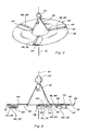
Figure 3 is a perspective view of a spreader disk assembly of the spreader ofFigure 1 , configured with a plurality of bats thereof positioned in a deployed mode for spreading; -
Figure 4 is a side view of the spreader disk assembly ofFigure 3 ; -
Figure 5 is a perspective view of the spreader disk assembly ofFigures 3-4 , configured with the bats thereof in a stowed mode for windrowing; -
Figure 6 is a side view of the spreader disk ofFigure 5 ; -
Figure 7 is another fragmentary side view of the harvesting machine ofFigure 1 , with the crop residue spreader configured in a mode for spreading the crop residue onto a field; -
Figure 8 is a fragmentary side view of the spreader disk assembly showing aspects of a locking mechanism thereof, illustrating locking a bat in the deployed mode; and -
Figure 9 is another fragmentary side view of the spreader disk assembly showing the locking mechanism locking a bat in the stowed position. - Referring now to the drawings, wherein like numerals refer to like parts, in
Figures 1 and2 , the rear end of a representativeagricultural harvesting machine 20, which is a combine, is shown.Machine 20 is of conventional construction and operation, and includes harvesting apparatus operable for cutting crops asmachine 20 moves forwardly over a field, as denoted byarrow F. Machine 20 also includes apparatus for conveying the cut crops intomachine 20, then threshing and separating grain from the MOG, including crop residue, which when harvesting grasses such as wheat, typically includes a large quantity of straw. The crop residue is then conveyed or propelled rearwardly withinmachine 20, as denoted by arrow DF, and discharged through adischarge outlet 22, which, in this instance, comprises a downwardly and rearwardly facing opening at the rear ofmachine 20. Aspreader assembly 24, is mounted generally belowdischarge outlet 22, and is partially concealed byside sheets 26, as shown.Spreader assembly 24 shown includes a pair of side by sidespreader disk assemblies 28, which are drivingly counter rotated by a suitable drive or drives, which here is depicted as a bevelgear shaft drive 30 contained withinmachine 20, and constructed and operable in the well known manner. Generally, eachspreader disk assembly 28 is supported by a downwardly extendingshaft 34 ofdrive 30 for rotation, as denoted by arrow R, about a centralrotational axis 32, such that theassemblies 28 counter rotated as illustrated. A more complete description ofdrive 30, as well as the layout and construction of spreader assemblies generally, is contained inUS 7,473,171 B1 , the disclosure of which is hereby incorporated herein by reference in its entirety. - Referring also to
Figs. 3, 4 ,5, 6 ,7 ,8 and 9 , eachspreader disk assembly 28 includes a generally planar,circular disk 36, and aspreader cone 38 to which thespreader disk 36 is be joined or secured for rotation withshaft 34, bothdisk 36 andcone 38 be fabricated from a suitable material such as a plastics or sheet metal.Spreader disk 36 has a substantially planarfirst surface 40, and an oppositesecond surface 42,rotational axis 32 extending through a central portion ofdisk 36 betweensurfaces Assembly 28 includes a plurality ofelongate bats 44 disposed onfirst surface 40 at angularly spaced locations aboutrotational axis 32, respectively. Here, threebats 44 are shown on eachdisk 36 at equally angularly spaced locations, although it should be recognised and understood that a greater or lesser number of bats can be used, a desired or required for a particular application. - Each
bat 44 has alongitudinal edge 46 pivotally or hingedly mounted by ahinge 48 todisk 36 for pivotal or hinged movement ofbat 44, as denoted by arrows HM, between a deployed position extending generally axially outwardly from the first surface (upwardly with the disk oriented as shown inFigures 3, 4 ,7 and8 ) for spreading, and a stowed position extending generally parallel to the first surface (Figures 1 ,2 ,5, 6 and9 (foreground)) for windrowing. - Each
disk assembly 28 includes abat support mechanism 50 in connection with eachbat 44, extending throughdisk 36, respectively. Eachbat support mechanism 50 includes an elongate support bracket 52 extending longitudinally through a slot orslots 54 throughdisk 36 and having afirst end 56 pivotally connected tobat 44, and asecond end 58 located on the opposite side ofdisk 36 adjacent tosecond surface 42. - Bracket 52 carries a locking mechanism 60, also on the opposite side of
disk 36 adjacent tosecond surface 42, configurable in a first manner for supporting and holdingbat 44 in the deployed position (Figures 3, 4 ,7 and8 ), and in a second manner for holding the bat in the stowed position (Figures 1 ,2 ,5 and 6 ). Locking mechanism 60 comprises a detent element 62 on or extending downwardly fromsecond surface 42, which is a cup shaped member having a slot therethrough extending from an edge of the cup to a center region thereof, and a resilientlyelongatable strap 64 having afirst end 66 captured and carried in a slot orslots 68 extending longitudinally along bracket 52, and a ball shapedsecond end 70 cooperatively receivable in the cup of detent element 62 withstrap 64 extending through the slot thereof. In a preferred configuration, bracket 52 has a U shape, and includes two parallel, spaced apartslots 68 with a channel disposed between the two legs of the U shape. Thefirst end 66 of strap has a T shape, and the ends of the T are slidably received inslots 68 to allow movement ofstrap 64 therealong. - Referring more particularly to
Figure 8 , wherein locking mechanism is illustrated in a bat deploying mode,first end 56 of bracket 52 is shaped so as to have anendmost edge 72 or edges that bear againstbat 44 for supporting it in its deployed mode, and which allows pivoting bracket 52 relative to the bat, and also the hinged movement of the bat itself, for hingedly moving or pivoting to the stowed position, as denoted by arrow HM.Second end 58 of bracket 52 preferably has a shape which enables anedge 74 to bear against an edge ofdisk 36 adjacent to slot 54 whenbat 44 is in the deployed mode, bracket 52 andbat 44 being restrained in this configuration by locatingstrap 64 inslots 68 as shown, such thatend 66 of the strap bears against bracket 52 at the end ofslots 68 closest tofirst end 56 and the strap is resiliently elongated in tension whenend 70 thereof is detained in detent element 62, such thatstrap 64 pulls against bracket 52 for holding it in this position, which, in turn, supports and holdsbat 44 in the upstanding position of the deployed mode. An optional detent slot 76 (Figure 9 ) can be provided in connection withslot 68 for receivingend 66 of the strap when in this position. This arrangement has been found to be advantageous for spreading as it is sufficiently robust for supporting and holdingbats 44 in the deployed position, for resisting forces exerted thereagainst by crop residue falling thereon and pressed thereagainst during the rotation ofdisk assembly 28. Then, as shown by arrow RC inFigure 8 , for reconfiguringbats 44 in the stowed position, e.g., shown inFigure 9 , end 70 ofstrap 64 can be grasped and pulled away from detent element 62, to elongatestrap 64 and remove it from the detent element as shown in dotted lines, which allows free hinged movement ofbat 44 as denoted by arrow HM. - Referring more particularly to
Figure 9 also which shows mechanism 60 in a bat stowing mode, end 66 ofstrap 64 can be slid withinslots 68 of bracket 52 to the end closest to end 56 of the bracket, as shown. As this is done, bracket 52 can be retracted through slot 54 (Figure 3 ) ofdisk 36. By pullingstrap 64 toward detent element 60, bracket 52 will be pivoted about apivotal connection 78 tobat 44, such thatend 58 of the bracket will be brought to bear againstsurface 42 ofdisk 36 atlocation 80.Strap 64 will then be resiliently elongated such that ball shaped end 70 can be detained in cup shaped detent element 62 in the bat stowing mode for holdingbat 44 in the stowed position shown.Disk 36 is now substantially flat, which is advantageous for windrowing. The end of theslot 68 that holds end 66 ofstrap 64 has taken a position above thepivotal conection 78, thus providing an over center action clamping action to the bracket 52. - As is apparent from the above description, the present invention enables
bats 44 to be simply and easily convertible between the deployed and stowed modes, by releasingstrap 64 from detent element 62, moving or repositioning the bat and the strap, and re-engaging the strap with the detent element. No removal of the bats, or the disks, is required. And, if a large number of bats is used, some of the bats, e.g., alternating ones, can be selectably moved to the stowed position, for altering the spreading characteristics. - As another advantage, in the deployed or spreading mode, the bats will operate conventionally to spread the crop residue discharged thereon in the well known manner, as illustrated in
Figure 7 . In the stowed mode, the bats will allow crop residue to flow thereover, while acting to decelerate and reduce the velocity of the crop residue flow, and contain the flow to a width suitable for a windrow, as illustrated bywindrow 82 inFigures 1 and2 . Here, it can be observed inFigure 2 , that this enables the crop residue to be placed on standingstubble 84 sufficiently gently so as to rest in the top of the stubble and not integrate therein, to enable better air circulation for drying, and easier raking and picking up for baling and the like. - In light of the foregoing, it should thus be apparent to those skilled in the art that there has been shown and described herein a spreader disk assembly convertible for windrowing which provides one or more of the advantages sought therefor, and overcomes one or more of the shortcomings, set forth above. However, it should also be apparent that, within the principles and scope of the invention, as defined by the accompanying claims, many changes are possible and contemplated, including in the details, materials, and arrangements of parts and elements which have been described and illustrated to explain the invention. Thus, while the foregoing description and discussion addresses certain preferred embodiments or elements of the invention, it should further be understood that concepts of the invention, as based upon the foregoing description and discussion, may be readily incorporated into or employed in other embodiments and constructions without departing from said scope of the invention.
Claims (11)
- A spreader disk assembly (28) for an agricultural harvesting machine (20), comprising:a disk (36) having a substantially planar first surface (40), a second surface (42) opposite the first surface (40), and a rotational axis (32) extending through a central portion of the disk (36) between the first and second surfaces;a plurality of elongate bats (44) disposed on the first surface (40) at angularly spaced locations about the rotational axis (32), respectively,characterised in that:each of the bats (44) has a longitudinal edge (46) pivotally mounted to the disk (36) for pivotal movement (HM) of the bat between a deployed position extending generally axially outwardly from the first surface (40), and a stowed position extending generally parallel to the first surface (40); andthe spreader disk assembly further comprises bat support mechanisms (50) extending through the disk (36) and connected to the bats (44), respectively, each of the support mechanisms being configurable in a bat deploying mode for lockingly supporting and holding the bat connected thereto in the deployed position, and in a bat stowing mode holding the bat connected thereto in the stowed position.
- A spreader disk assembly according to claim 1, wherein each of the bat support mechanisms (50) comprises a resilient element (64) configured such that, when in the bat stowing mode, the mechanism will resiliently bias the bat (44) against the first surface (40) in the stowed position.
- A spreader disk assembly according to claim 1 or 2, wherein each of the bats (44) is generally flat and will lay substantially flat against the first surface (40) when in the stowed position.
- A spreader disk assembly according to any of the preceding claims, wherein each of the bat support mechanisms (50) comprises an elongate support bracket (52) extending longitudinally through at least one slot (54) through the disk (36) and having a first end (56) connected to the bat (44), and a second end (56) located adjacent to the second surface (42), the bracket carrying a locking mechanism (60) configurable in a first manner for supporting and holding the bat in the deployed position, and in a second manner for holding the bat in the stowed position.
- A spreader disk assembly according to claim 4, wherein the first end (56) of the support bracket (52) is pivotally mounted to the bat (44).
- A spreader disk assembly according to claim 4 or 5, wherein the locking mechanism (60) comprises a detent element (62) on the second surface (42) and a strap (64) having one end (66) captured and carried in a slot (68) extending longitudinally along the bracket (52) so as to be movable longitudinally relative thereto, and an opposite end (70) configured to be cooperatively engaged and held by the detent element (62), wherein the strap (64) is movable to one end of the slot (68) and engageable with the detent element (62) for releasably holding the bat (44) in the deployed position, and wherein the strap (64) is movable to an opposite end of the slot and engageable with the detent element for releasably holding the bat in the stowed position.
- A spreader disk assembly according to claim 6, wherein the strap (64) of the locking mechanism (60) is a resiliently elongatable strap.
- A spreader disk assembly according to any of the preceding claims, comprising two of the disks (36) disposed in side-by-side relation.
- A harvesting machine (20) comprising a spreader disk assembly (28) according to any of the preceding claims, wherein the disk (36) is supported below a crop residue discharge outlet (22) of the harvesting machine (20) and is connected in rotatably driven relation to a drive (30) operable for rotating the disk (36) about the rotational axis (32) in a manner such that crop residue discharged onto the disk when rotating will be propelled radially outwardly by the bats (44) when in the deployed position, and will pass over the bats when in the stowed position.
- A harvesting machine according to claim 9, wherein the disk (36) is supported below the crop residue discharche outlet (22) such that crop residue discharged therefrom will impinge the first surface (40), and such that, when the disk is rotated, if the bats (44) are in the deployed position the crop residue will be spread by the spreader disk assembly (28) in a swath having a sideward extent greater than a sideward extent of the disk (36), and if the bats (44) are in the stowed position the crop residue that impinges the disk will fall from the disk in a windrow (82) having a sideward extent about equal to the sideward extent of the disk.
- A harvesting machine according to claim 9 or 10, when depending on claim 8, wherein the drive (30) is connected to the disks (36) and operable for counter rotating the disks about the rotational axes (32), respectively, such that when the bats (44) are in the deployed position and the disks are rotated any crop residue that impinges the first surfaces (40) of the disks will be spread in a dispersed pattern by the bats, and such that when the bats are in the stowed position and the disks are rotated any crop residue that impinges the first surfaces (40) of the disks will be decelerated and dropped substantially directly downwardly from the disks.
Applications Claiming Priority (1)
| Application Number | Priority Date | Filing Date | Title |
|---|---|---|---|
| US27193909P | 2009-07-28 | 2009-07-28 |
Publications (3)
| Publication Number | Publication Date |
|---|---|
| EP2279654A2 true EP2279654A2 (en) | 2011-02-02 |
| EP2279654A3 EP2279654A3 (en) | 2013-10-30 |
| EP2279654B1 EP2279654B1 (en) | 2015-05-20 |
Family
ID=42985211
Family Applications (1)
| Application Number | Title | Priority Date | Filing Date |
|---|---|---|---|
| EP20100170743 Active EP2279654B1 (en) | 2009-07-28 | 2010-07-26 | Spreader disk assembly convertible for windrowing |
Country Status (2)
| Country | Link |
|---|---|
| US (1) | US8070570B2 (en) |
| EP (1) | EP2279654B1 (en) |
Cited By (1)
| Publication number | Priority date | Publication date | Assignee | Title |
|---|---|---|---|---|
| WO2024074829A1 (en) * | 2022-10-04 | 2024-04-11 | Simcox Graham | Apparatus for use in spreading of materials |
Families Citing this family (13)
| Publication number | Priority date | Publication date | Assignee | Title |
|---|---|---|---|---|
| US8585475B2 (en) * | 2011-04-19 | 2013-11-19 | Cnh America Llc | Crop residue distribution apparatus and system with cooperatively movable deflector door and spreader assembly |
| US8574048B1 (en) * | 2012-07-10 | 2013-11-05 | Cnh America Llc | Combine spreader arrangement having independently positionable spreader disks |
| US9107349B2 (en) | 2012-08-31 | 2015-08-18 | Cnh Industrial America Llc | System and method for controlling the spreading of crop residue expelled from an agricultural combine |
| US9137944B2 (en) | 2012-08-31 | 2015-09-22 | Cnh Industrial America Llc | Windrow door for an agricultural combine |
| US8992294B2 (en) | 2012-08-31 | 2015-03-31 | Cnh Industrial America Llc | Windrow door assembly for an agricultural combine |
| US9370141B2 (en) | 2012-12-11 | 2016-06-21 | Cnh Industrial America Llc | Spreader system for an agricultural harvester |
| US9345198B2 (en) * | 2014-02-14 | 2016-05-24 | Deere & Company | Residue chopping and distribution arrangement for a combine harvester |
| US9801340B2 (en) * | 2015-04-30 | 2017-10-31 | Cnh Industrial America Llc | Spreader arrangement for an agricultural harvester |
| CN105394025B (en) * | 2015-09-21 | 2018-08-21 | 江苏大学 | A kind of degradable sphere automatic release device of unmanned plane |
| US10159186B2 (en) * | 2016-08-26 | 2018-12-25 | CNH Industrial America, LLC | Corn harvester with tall corn attachment and auger and associated methods |
| US10159188B2 (en) * | 2016-08-26 | 2018-12-25 | Cnh Industrial America Llc | Corn harvester with tall corn attachment and associated methods |
| US11778947B2 (en) * | 2021-01-13 | 2023-10-10 | Deere & Company | Automated adjustable angle of incidence fan for cleaning sugarcane |
| US12004447B2 (en) * | 2021-10-01 | 2024-06-11 | Cnh Industrial America Llc | Pivotable windrow chute for combine harvester |
Citations (2)
| Publication number | Priority date | Publication date | Assignee | Title |
|---|---|---|---|---|
| US6726131B2 (en) | 2001-12-27 | 2004-04-27 | All-State Industries, Inc. | Rotatable distribution plate for particulate material |
| US7473171B1 (en) | 2007-07-26 | 2009-01-06 | Cnh America Llc | Molded spreader disk |
Family Cites Families (23)
| Publication number | Priority date | Publication date | Assignee | Title |
|---|---|---|---|---|
| US3394892A (en) * | 1965-10-23 | 1968-07-30 | Cyclone Seeder Co | Material spreader |
| US3853288A (en) * | 1967-07-17 | 1974-12-10 | H Bode | Encasement for the tail section of a rocket with a central nozzle and extendible control vanes |
| US3539113A (en) * | 1968-07-09 | 1970-11-10 | Letco Inc | Distributor means for a fertilizer spreader |
| NL190570C (en) * | 1978-05-05 | 1994-05-02 | Lely Nv C Van Der | Device for spreading granular and / or powdery material. |
| DE2908949C2 (en) * | 1979-03-07 | 1982-07-15 | Amazonen-Werke H. Dreyer Gmbh & Co Kg, 4507 Hasbergen | Centrifugal fertilizer spreader |
| SU1021383A1 (en) | 1982-03-12 | 1983-06-07 | Кубанский Ордена Трудового Красного Знамени Сельскохозяйственный Институт | Centrifugal working member for spreading loose materials |
| SU1021384A1 (en) | 1982-03-22 | 1983-06-07 | Кубанский Ордена Трудового Красного Знамени Сельскохозяйственный Институт | Working member for spreading loose materials |
| US4549697A (en) * | 1983-06-09 | 1985-10-29 | Swenson Spreader Company | Spreader guard |
| US4617942A (en) * | 1985-01-24 | 1986-10-21 | Garner David L | Chaff spreading apparatus |
| US4936526A (en) * | 1989-02-02 | 1990-06-26 | Williams International Corporation | Foldable counter-rotating propfan blades |
| US4979876A (en) * | 1989-06-19 | 1990-12-25 | Williams International Corporation | Foldable propulsion system |
| DK101192A (en) * | 1992-08-12 | 1994-02-13 | Laursen As A P | Rotating spreading disc with removable blades for spreading non-corrosive material |
| US5570997A (en) * | 1995-07-17 | 1996-11-05 | Pratt; Charles W. | Horizontal windmill with folding blades |
| US5976011A (en) * | 1997-12-31 | 1999-11-02 | Hartman; Everett A. | Straw and chaff spreader assembly |
| US6149079A (en) * | 1998-09-03 | 2000-11-21 | Turfco Manufacturing, Incorporated | Broadcast spreading top dresser |
| US6238286B1 (en) * | 1999-08-06 | 2001-05-29 | Deere & Company | Crop residue spreader |
| US6761331B2 (en) * | 2002-03-19 | 2004-07-13 | Raytheon Company | Missile having deployment mechanism for stowable fins |
| US6699013B2 (en) * | 2002-05-31 | 2004-03-02 | Quantum Corporation | Forced air cooling fan having pivotal fan blades for unidirectional air flow |
| US6860713B2 (en) * | 2002-11-27 | 2005-03-01 | Nidec Corporation | Fan with collapsible blades, redundant fan system, and related method |
| US6972956B2 (en) * | 2003-01-16 | 2005-12-06 | Hewlett-Packard Development Company, L.P. | Collapsible fan and system and method incorporating same |
| US7331855B2 (en) * | 2005-07-15 | 2008-02-19 | Deere & Company | Wide-spread impeller spreader for harvesting combine |
| US7635299B2 (en) * | 2007-09-28 | 2009-12-22 | Cnh America Llc | Windrow forming construction |
| DE202009010907U1 (en) * | 2009-03-26 | 2009-11-19 | Deere & Company, Moline | Harvest crop shred and distribution arrangement for a combine harvester |
-
2010
- 2010-07-26 EP EP20100170743 patent/EP2279654B1/en active Active
- 2010-07-27 US US12/844,501 patent/US8070570B2/en active Active
Patent Citations (2)
| Publication number | Priority date | Publication date | Assignee | Title |
|---|---|---|---|---|
| US6726131B2 (en) | 2001-12-27 | 2004-04-27 | All-State Industries, Inc. | Rotatable distribution plate for particulate material |
| US7473171B1 (en) | 2007-07-26 | 2009-01-06 | Cnh America Llc | Molded spreader disk |
Cited By (1)
| Publication number | Priority date | Publication date | Assignee | Title |
|---|---|---|---|---|
| WO2024074829A1 (en) * | 2022-10-04 | 2024-04-11 | Simcox Graham | Apparatus for use in spreading of materials |
Also Published As
| Publication number | Publication date |
|---|---|
| US20110028193A1 (en) | 2011-02-03 |
| US8070570B2 (en) | 2011-12-06 |
| EP2279654A3 (en) | 2013-10-30 |
| EP2279654B1 (en) | 2015-05-20 |
Similar Documents
| Publication | Publication Date | Title |
|---|---|---|
| EP2279654B1 (en) | Spreader disk assembly convertible for windrowing | |
| US6719627B2 (en) | Multi-position linkage and locking mechanism for a crop residue spreader and/or chopper | |
| EP2138024B1 (en) | Active spreader for an agricultural combine | |
| RU2561524C2 (en) | Frontal device for harvesting stalked material | |
| US9930832B2 (en) | Mower with reconfigurable crop material ejection | |
| RU2378818C1 (en) | Device for picking of fruit | |
| US7131253B2 (en) | Crop harvesting header with crop divider members carried on the reel | |
| JPS62500213A (en) | Crop harvesting machine and crop harvesting method | |
| US6338236B1 (en) | Mechanized harvesting machine with rotating picking elements | |
| US20140260167A1 (en) | Cam action windguard | |
| DK2789224T3 (en) | Mower and mower unit | |
| US4735216A (en) | Straw chopper and spreader assembly | |
| US5134837A (en) | Crop pickup and seed harvesting device | |
| US7062897B2 (en) | Gathering and picking device | |
| CN108024503B (en) | Plant propulsion unit for mounting on drums of combine harvester headers | |
| US4206581A (en) | Corn harvester | |
| CA2463380C (en) | Machine for mowing stalk-like crops | |
| US4291521A (en) | Husk separator for corn harvester | |
| US20040144073A1 (en) | Gathering and picking device | |
| JPS6050409B2 (en) | combine | |
| JPH0649151Y2 (en) | Feeder house front board device in combine | |
| EP4009768A1 (en) | Knife brush for a header reel | |
| Khan | Harvesting and threshing of paddy | |
| JPH0144030Y2 (en) | ||
| JP2001086848A (en) | Threshing machine dust treatment equipment |
Legal Events
| Date | Code | Title | Description |
|---|---|---|---|
| PUAI | Public reference made under article 153(3) epc to a published international application that has entered the european phase |
Free format text: ORIGINAL CODE: 0009012 |
|
| AK | Designated contracting states |
Kind code of ref document: A2 Designated state(s): AL AT BE BG CH CY CZ DE DK EE ES FI FR GB GR HR HU IE IS IT LI LT LU LV MC MK MT NL NO PL PT RO SE SI SK SM TR |
|
| AX | Request for extension of the european patent |
Extension state: BA ME RS |
|
| PUAL | Search report despatched |
Free format text: ORIGINAL CODE: 0009013 |
|
| AK | Designated contracting states |
Kind code of ref document: A3 Designated state(s): AL AT BE BG CH CY CZ DE DK EE ES FI FR GB GR HR HU IE IS IT LI LT LU LV MC MK MT NL NO PL PT RO SE SI SK SM TR |
|
| AX | Request for extension of the european patent |
Extension state: BA ME RS |
|
| RIC1 | Information provided on ipc code assigned before grant |
Ipc: A01D 41/12 20060101AFI20130925BHEP Ipc: A01F 29/12 20060101ALI20130925BHEP |
|
| RAP1 | Party data changed (applicant data changed or rights of an application transferred) |
Owner name: CNH INDUSTRIAL BELGIUM NV |
|
| 17P | Request for examination filed |
Effective date: 20140430 |
|
| RBV | Designated contracting states (corrected) |
Designated state(s): AL AT BE BG CH CY CZ DE DK EE ES FI FR GB GR HR HU IE IS IT LI LT LU LV MC MK MT NL NO PL PT RO SE SI SK SM TR |
|
| GRAP | Despatch of communication of intention to grant a patent |
Free format text: ORIGINAL CODE: EPIDOSNIGR1 |
|
| INTG | Intention to grant announced |
Effective date: 20141215 |
|
| GRAS | Grant fee paid |
Free format text: ORIGINAL CODE: EPIDOSNIGR3 |
|
| GRAA | (expected) grant |
Free format text: ORIGINAL CODE: 0009210 |
|
| AK | Designated contracting states |
Kind code of ref document: B1 Designated state(s): AL AT BE BG CH CY CZ DE DK EE ES FI FR GB GR HR HU IE IS IT LI LT LU LV MC MK MT NL NO PL PT RO SE SI SK SM TR |
|
| REG | Reference to a national code |
Ref country code: GB Ref legal event code: FG4D |
|
| REG | Reference to a national code |
Ref country code: CH Ref legal event code: EP |
|
| REG | Reference to a national code |
Ref country code: AT Ref legal event code: REF Ref document number: 727214 Country of ref document: AT Kind code of ref document: T Effective date: 20150615 |
|
| REG | Reference to a national code |
Ref country code: IE Ref legal event code: FG4D |
|
| REG | Reference to a national code |
Ref country code: DE Ref legal event code: R096 Ref document number: 602010024711 Country of ref document: DE |
|
| REG | Reference to a national code |
Ref country code: AT Ref legal event code: MK05 Ref document number: 727214 Country of ref document: AT Kind code of ref document: T Effective date: 20150520 |
|
| REG | Reference to a national code |
Ref country code: LT Ref legal event code: MG4D |
|
| REG | Reference to a national code |
Ref country code: NL Ref legal event code: MP Effective date: 20150520 |
|
| PG25 | Lapsed in a contracting state [announced via postgrant information from national office to epo] |
Ref country code: PT Free format text: LAPSE BECAUSE OF FAILURE TO SUBMIT A TRANSLATION OF THE DESCRIPTION OR TO PAY THE FEE WITHIN THE PRESCRIBED TIME-LIMIT Effective date: 20150921 Ref country code: NO Free format text: LAPSE BECAUSE OF FAILURE TO SUBMIT A TRANSLATION OF THE DESCRIPTION OR TO PAY THE FEE WITHIN THE PRESCRIBED TIME-LIMIT Effective date: 20150820 Ref country code: HR Free format text: LAPSE BECAUSE OF FAILURE TO SUBMIT A TRANSLATION OF THE DESCRIPTION OR TO PAY THE FEE WITHIN THE PRESCRIBED TIME-LIMIT Effective date: 20150520 Ref country code: FI Free format text: LAPSE BECAUSE OF FAILURE TO SUBMIT A TRANSLATION OF THE DESCRIPTION OR TO PAY THE FEE WITHIN THE PRESCRIBED TIME-LIMIT Effective date: 20150520 Ref country code: ES Free format text: LAPSE BECAUSE OF FAILURE TO SUBMIT A TRANSLATION OF THE DESCRIPTION OR TO PAY THE FEE WITHIN THE PRESCRIBED TIME-LIMIT Effective date: 20150520 Ref country code: LT Free format text: LAPSE BECAUSE OF FAILURE TO SUBMIT A TRANSLATION OF THE DESCRIPTION OR TO PAY THE FEE WITHIN THE PRESCRIBED TIME-LIMIT Effective date: 20150520 |
|
| PG25 | Lapsed in a contracting state [announced via postgrant information from national office to epo] |
Ref country code: AT Free format text: LAPSE BECAUSE OF FAILURE TO SUBMIT A TRANSLATION OF THE DESCRIPTION OR TO PAY THE FEE WITHIN THE PRESCRIBED TIME-LIMIT Effective date: 20150520 Ref country code: LV Free format text: LAPSE BECAUSE OF FAILURE TO SUBMIT A TRANSLATION OF THE DESCRIPTION OR TO PAY THE FEE WITHIN THE PRESCRIBED TIME-LIMIT Effective date: 20150520 Ref country code: BG Free format text: LAPSE BECAUSE OF FAILURE TO SUBMIT A TRANSLATION OF THE DESCRIPTION OR TO PAY THE FEE WITHIN THE PRESCRIBED TIME-LIMIT Effective date: 20150820 Ref country code: GR Free format text: LAPSE BECAUSE OF FAILURE TO SUBMIT A TRANSLATION OF THE DESCRIPTION OR TO PAY THE FEE WITHIN THE PRESCRIBED TIME-LIMIT Effective date: 20150821 Ref country code: IS Free format text: LAPSE BECAUSE OF FAILURE TO SUBMIT A TRANSLATION OF THE DESCRIPTION OR TO PAY THE FEE WITHIN THE PRESCRIBED TIME-LIMIT Effective date: 20150920 |
|
| PG25 | Lapsed in a contracting state [announced via postgrant information from national office to epo] |
Ref country code: EE Free format text: LAPSE BECAUSE OF FAILURE TO SUBMIT A TRANSLATION OF THE DESCRIPTION OR TO PAY THE FEE WITHIN THE PRESCRIBED TIME-LIMIT Effective date: 20150520 Ref country code: DK Free format text: LAPSE BECAUSE OF FAILURE TO SUBMIT A TRANSLATION OF THE DESCRIPTION OR TO PAY THE FEE WITHIN THE PRESCRIBED TIME-LIMIT Effective date: 20150520 |
|
| REG | Reference to a national code |
Ref country code: DE Ref legal event code: R097 Ref document number: 602010024711 Country of ref document: DE |
|
| PG25 | Lapsed in a contracting state [announced via postgrant information from national office to epo] |
Ref country code: MC Free format text: LAPSE BECAUSE OF FAILURE TO SUBMIT A TRANSLATION OF THE DESCRIPTION OR TO PAY THE FEE WITHIN THE PRESCRIBED TIME-LIMIT Effective date: 20150520 Ref country code: CZ Free format text: LAPSE BECAUSE OF FAILURE TO SUBMIT A TRANSLATION OF THE DESCRIPTION OR TO PAY THE FEE WITHIN THE PRESCRIBED TIME-LIMIT Effective date: 20150520 Ref country code: PL Free format text: LAPSE BECAUSE OF FAILURE TO SUBMIT A TRANSLATION OF THE DESCRIPTION OR TO PAY THE FEE WITHIN THE PRESCRIBED TIME-LIMIT Effective date: 20150520 Ref country code: SK Free format text: LAPSE BECAUSE OF FAILURE TO SUBMIT A TRANSLATION OF THE DESCRIPTION OR TO PAY THE FEE WITHIN THE PRESCRIBED TIME-LIMIT Effective date: 20150520 Ref country code: RO Free format text: LAPSE BECAUSE OF NON-PAYMENT OF DUE FEES Effective date: 20150520 |
|
| REG | Reference to a national code |
Ref country code: CH Ref legal event code: PL |
|
| PLBE | No opposition filed within time limit |
Free format text: ORIGINAL CODE: 0009261 |
|
| STAA | Information on the status of an ep patent application or granted ep patent |
Free format text: STATUS: NO OPPOSITION FILED WITHIN TIME LIMIT |
|
| PG25 | Lapsed in a contracting state [announced via postgrant information from national office to epo] |
Ref country code: LU Free format text: LAPSE BECAUSE OF FAILURE TO SUBMIT A TRANSLATION OF THE DESCRIPTION OR TO PAY THE FEE WITHIN THE PRESCRIBED TIME-LIMIT Effective date: 20150726 |
|
| REG | Reference to a national code |
Ref country code: IE Ref legal event code: MM4A |
|
| 26N | No opposition filed |
Effective date: 20160223 |
|
| PG25 | Lapsed in a contracting state [announced via postgrant information from national office to epo] |
Ref country code: LI Free format text: LAPSE BECAUSE OF NON-PAYMENT OF DUE FEES Effective date: 20150731 Ref country code: CH Free format text: LAPSE BECAUSE OF NON-PAYMENT OF DUE FEES Effective date: 20150731 |
|
| PG25 | Lapsed in a contracting state [announced via postgrant information from national office to epo] |
Ref country code: SI Free format text: LAPSE BECAUSE OF FAILURE TO SUBMIT A TRANSLATION OF THE DESCRIPTION OR TO PAY THE FEE WITHIN THE PRESCRIBED TIME-LIMIT Effective date: 20150520 |
|
| REG | Reference to a national code |
Ref country code: FR Ref legal event code: PLFP Year of fee payment: 7 |
|
| PG25 | Lapsed in a contracting state [announced via postgrant information from national office to epo] |
Ref country code: IE Free format text: LAPSE BECAUSE OF NON-PAYMENT OF DUE FEES Effective date: 20150726 |
|
| PG25 | Lapsed in a contracting state [announced via postgrant information from national office to epo] |
Ref country code: BE Free format text: LAPSE BECAUSE OF FAILURE TO SUBMIT A TRANSLATION OF THE DESCRIPTION OR TO PAY THE FEE WITHIN THE PRESCRIBED TIME-LIMIT Effective date: 20150520 |
|
| PG25 | Lapsed in a contracting state [announced via postgrant information from national office to epo] |
Ref country code: MT Free format text: LAPSE BECAUSE OF FAILURE TO SUBMIT A TRANSLATION OF THE DESCRIPTION OR TO PAY THE FEE WITHIN THE PRESCRIBED TIME-LIMIT Effective date: 20150520 |
|
| PG25 | Lapsed in a contracting state [announced via postgrant information from national office to epo] |
Ref country code: SM Free format text: LAPSE BECAUSE OF FAILURE TO SUBMIT A TRANSLATION OF THE DESCRIPTION OR TO PAY THE FEE WITHIN THE PRESCRIBED TIME-LIMIT Effective date: 20150520 Ref country code: HU Free format text: LAPSE BECAUSE OF FAILURE TO SUBMIT A TRANSLATION OF THE DESCRIPTION OR TO PAY THE FEE WITHIN THE PRESCRIBED TIME-LIMIT; INVALID AB INITIO Effective date: 20100726 |
|
| REG | Reference to a national code |
Ref country code: FR Ref legal event code: PLFP Year of fee payment: 8 |
|
| PG25 | Lapsed in a contracting state [announced via postgrant information from national office to epo] |
Ref country code: NL Free format text: LAPSE BECAUSE OF FAILURE TO SUBMIT A TRANSLATION OF THE DESCRIPTION OR TO PAY THE FEE WITHIN THE PRESCRIBED TIME-LIMIT Effective date: 20150520 Ref country code: CY Free format text: LAPSE BECAUSE OF FAILURE TO SUBMIT A TRANSLATION OF THE DESCRIPTION OR TO PAY THE FEE WITHIN THE PRESCRIBED TIME-LIMIT Effective date: 20150520 Ref country code: SE Free format text: LAPSE BECAUSE OF FAILURE TO SUBMIT A TRANSLATION OF THE DESCRIPTION OR TO PAY THE FEE WITHIN THE PRESCRIBED TIME-LIMIT Effective date: 20150520 |
|
| PG25 | Lapsed in a contracting state [announced via postgrant information from national office to epo] |
Ref country code: TR Free format text: LAPSE BECAUSE OF FAILURE TO SUBMIT A TRANSLATION OF THE DESCRIPTION OR TO PAY THE FEE WITHIN THE PRESCRIBED TIME-LIMIT Effective date: 20150520 |
|
| PG25 | Lapsed in a contracting state [announced via postgrant information from national office to epo] |
Ref country code: MK Free format text: LAPSE BECAUSE OF FAILURE TO SUBMIT A TRANSLATION OF THE DESCRIPTION OR TO PAY THE FEE WITHIN THE PRESCRIBED TIME-LIMIT Effective date: 20150520 |
|
| REG | Reference to a national code |
Ref country code: FR Ref legal event code: PLFP Year of fee payment: 9 |
|
| PG25 | Lapsed in a contracting state [announced via postgrant information from national office to epo] |
Ref country code: AL Free format text: LAPSE BECAUSE OF FAILURE TO SUBMIT A TRANSLATION OF THE DESCRIPTION OR TO PAY THE FEE WITHIN THE PRESCRIBED TIME-LIMIT Effective date: 20150520 |
|
| PGFP | Annual fee paid to national office [announced via postgrant information from national office to epo] |
Ref country code: GB Payment date: 20190724 Year of fee payment: 10 |
|
| REG | Reference to a national code |
Ref country code: DE Ref legal event code: R084 Ref document number: 602010024711 Country of ref document: DE |
|
| REG | Reference to a national code |
Ref country code: DE Ref legal event code: R082 Ref document number: 602010024711 Country of ref document: DE Representative=s name: MEISSNER BOLTE PATENTANWAELTE RECHTSANWAELTE P, DE |
|
| GBPC | Gb: european patent ceased through non-payment of renewal fee |
Effective date: 20200726 |
|
| PG25 | Lapsed in a contracting state [announced via postgrant information from national office to epo] |
Ref country code: GB Free format text: LAPSE BECAUSE OF NON-PAYMENT OF DUE FEES Effective date: 20200726 |
|
| PGFP | Annual fee paid to national office [announced via postgrant information from national office to epo] |
Ref country code: DE Payment date: 20250728 Year of fee payment: 16 |
|
| PGFP | Annual fee paid to national office [announced via postgrant information from national office to epo] |
Ref country code: IT Payment date: 20250721 Year of fee payment: 16 |
|
| PGFP | Annual fee paid to national office [announced via postgrant information from national office to epo] |
Ref country code: FR Payment date: 20250725 Year of fee payment: 16 |