EP2278723A2 - Wireless communication apparatus and wireless communication method for detecting electric field intensity of wirelss channel - Google Patents
Wireless communication apparatus and wireless communication method for detecting electric field intensity of wirelss channel Download PDFInfo
- Publication number
- EP2278723A2 EP2278723A2 EP10164419A EP10164419A EP2278723A2 EP 2278723 A2 EP2278723 A2 EP 2278723A2 EP 10164419 A EP10164419 A EP 10164419A EP 10164419 A EP10164419 A EP 10164419A EP 2278723 A2 EP2278723 A2 EP 2278723A2
- Authority
- EP
- European Patent Office
- Prior art keywords
- wireless
- electric field
- channel
- field intensity
- wireless communication
- Prior art date
- Legal status (The legal status is an assumption and is not a legal conclusion. Google has not performed a legal analysis and makes no representation as to the accuracy of the status listed.)
- Granted
Links
Images




Classifications
-
- H—ELECTRICITY
- H04—ELECTRIC COMMUNICATION TECHNIQUE
- H04B—TRANSMISSION
- H04B17/00—Monitoring; Testing
- H04B17/30—Monitoring; Testing of propagation channels
- H04B17/382—Monitoring; Testing of propagation channels for resource allocation, admission control or handover
-
- H—ELECTRICITY
- H04—ELECTRIC COMMUNICATION TECHNIQUE
- H04B—TRANSMISSION
- H04B17/00—Monitoring; Testing
- H04B17/30—Monitoring; Testing of propagation channels
- H04B17/309—Measuring or estimating channel quality parameters
- H04B17/318—Received signal strength
Definitions
- the present invention relates generally to a wireless communication apparatus and a wireless communication method for detecting an electric field intensity of a wireless channel.
- a preset wireless frequency band is divided into a plurality of wireless channels in predetermined band widths so as not to overlap each other. Any one of the wireless channels is selected, and wireless communication between ratio communication apparatuses is performed in the selected wireless channel.
- a wireless communication apparatus having a function of transmitting/receiving data and a function of detecting the electric field intensity of a wireless channel for transmitting/receiving the data in order to continuously maintain good communication environments.
- Jpn. Pat. Appln. KOKAI Publication No. 2003-151062 discloses a wireless apparatus comprising a wireless unit configured to perform data communication, a control unit configured to read reception level output from the wireless unit using two channels of different frequencies, and a storage unit configured to store the read reception level.
- the apparatus has a problem in that the reception level cannot be detected while data is transmitted/received.
- a wireless communication apparatus comprising two wireless units.
- One of the wireless units is used for data transmission/reception, and the other wireless unit is used for detecting the electric field intensities of a plurality of wireless channels in order to find a wireless channel whose communication state is excellent.
- the electric field intensity of the wireless channel used for transmitting/receiving data is detected. Consequently, it becomes unclear whether the detection result of the wireless channel used is a result of detecting the electric field intensity accompanying transmission/reception of data, a result of detecting the electric field intensity of an interference wave, or a result of detection of both of the electric field intensities. That is, there is a problem in that the electric field intensity for determining the communication state of the wireless channel used cannot be detected.
- An object of the present invention is to obtain the electric field intensity of a wireless channel used without detecting the electric field intensity of the wireless channel.
- a wireless communication apparatus comprises a communication unit configured to wirelessly communicate with another wireless communication apparatus using a first wireless channel; a detection unit configured to detect electric field intensities of wireless channels except for the first wireless channel; and a control unit configured to calculate an electric field intensity of the first wireless channel based on the electric field intensities of the wireless channels detected by the detection unit.
- a wireless communication method for a wireless communication apparatus comprising a communication unit configured to wirelessly communicate with another wireless communication apparatus using a first wireless channel, the method comprises detecting electric field intensities of wireless channels except for the first wireless channel; and calculating an electric field intensity of the first wireless channel based on the electric field intensities of the wireless channels.
- FIG. 1 is a schematic configuration diagram of a wireless communication system A in the embodiment.
- the wireless communication system A comprises a wireless relay device 1 connected to another wireless relay device or external apparatus via a communication network N, and a plurality of wireless terminal devices 2 connected to the wireless relay device 1 via wireless waves.
- any one of a plurality of wireless channels obtained by dividing a preset frequency band into a plurality of pieces so as not to overlap each other is used, and wireless communication is performed between the wireless relay device 1 and the ratio terminal device 2.
- a frequency band of 2.4 GHz is divided into a total of 16 channels of channel 11 to channel 26.
- communication is performed between the wireless relay device 1 and the wireless terminal device 2.
- the wireless relay device 1, the external apparatus, and the wireless terminal device 2 will be also collectively called wireless communication apparatuses.
- FIG. 2 is a schematic configuration diagram of the wireless relay device 1.
- the wireless relay device 1 comprises a control unit 10, a storage unit 11, a terminal information memory 12, a timer 13, a wireless transmission/reception unit 14, a detection unit 15, a switch unit (SW) 16, an interface (I/F) unit 17, a buffer memory 18, an antenna 19, and the like which are electrically connected to one another.
- SW switch unit
- I/F interface
- the control unit 10 comprises a central processing unit (CPU), a read only memory (ROM), a random access memory (RAM), and the like.
- the control unit 10 reads a designated program, table, or data from various programs, various tables, data, and the like stored in the storage unit 11 and the terminal information memory 12, expands it in a work area in the RAM, the storage unit 11, or the terminal information memory 12, executes various processes in cooperation with the program, stores the process result in a predetermined region in the RAM, the storage unit 11, or the terminal information memory 12, and instructs the units in the wireless relay device 1 to generally control overall operation of the wireless relay device 1.
- CPU central processing unit
- ROM read only memory
- RAM random access memory
- the control unit 10 selects and determines a wireless channel having low interference wave level and excellent wave condition in the wireless frequency band which is divided into a plurality of wireless channels as a wireless channel (use channel) to be used in the wireless transmission/reception unit 14 at the time of performing wireless communication with the wireless terminal device 2.
- the control unit 10 periodically executes, by the detection unit 15, energy scanning process of detecting the electric field intensities of the plurality of wireless channels which can be selected.
- the energy scanning process is executed independently of data transmitting/receiving process executed by the wireless transmission/reception unit 14.
- the electric field intensities of the wireless channels except for the wireless channel (use channel) which is used in the wireless transmission/reception unit 14 in the plurality of wireless channels are detected by the detection unit 15. Based on the electric field intensities of the wireless channels detected by the detection unit 15, an estimated value of the electric field intensity of the use channel is calculated.
- the smoothing process includes three kinds of processes
- the comparing process includes two kinds of processes. Any one of the processes is preset as the process of calculating the estimated value.
- any of the following first to third smoothing processes is performed in the frequency directions of the wireless channels on the electric fields of the wireless channels whose electric field intensities are detected by the detection unit 15 except for the use channel, and the value calculated by the process becomes the estimated value of the electric field intensity of the use channel.
- an average value of the electric field intensities of two wireless channels existing below and above the use channel is calculated.
- the use channel is channel 20
- the average value of the electric field intensities of channels 19 and 21 is calculated as the estimated value of the electric field intensity of the use channel (channel 20). It is assumed that the smaller the number of a channel, the lower the frequency.
- an average value of the electric field intensities of a plurality of preset wireless channels existing below and above the use channel is calculated. For example, when the use channel is channel 20 and the plurality of preset wireless channels are two wireless channels 18 and 19 below the use channel and two wireless channels 21 and 22 above the use channel, the average value of the electric field intensities of channels 18, 19, 21, and 22 is calculated as the estimated value of the electric field intensity of the use channel (channel 20).
- a weighted average value of the electric field intensities of a plurality of preset wireless channels below and above the use channel is calculated.
- the use channel is channel 20
- the plurality of preset wireless channels are two wireless channels 18 and 19 below the use channel and two wireless channels 21 and 22 above the use channel, and each of the electric field intensities of channels 18, 19, 21, and 22 is weighted
- the average value of the weighted electric field intensities of channels 18, 19, 21, and 22 is calculated as the estimated value of the electric field intensity of the use channel (channel 20).
- the comparing process includes a first comparing process and a second comparing process.
- the electric field intensities of two wireless channels below and above the use channel are compared, and the higher electric field intensity of the wireless channel is used as the estimated value of the electric field intensity of the use channel.
- the use channel is channel 20
- the higher one of the electric field intensities of channels 19 and 21 is used as the estimated value of the electric field intensity of the use channel (channel 20).
- the highest one of electric field intensities of a plurality of preset wireless channels existing below and above the use channel is calculated as the estimated value of the electric field intensity of a wireless channel used in the wireless transmission/reception unit 14.
- the use channel is channel 20 and the plurality of preset wireless channels are two wireless channels 18 and 19 below the use channel and two wireless channels 21 and 22 above the use channel
- the highest one of the electric field intensities of channels 18, 19, 21, and 22 is calculated as the estimated value of the electric field intensity of the use channel (channel 20).
- the storage unit 11 is an electrically erasable and programmable nonvolatile memory such as a magnetic or optical recording medium or a semiconductor memory, and is fixedly or detachably attached in the wireless relay device 1.
- programs for processes in the embodiment executed by the control unit 10 various programs, and various tables, data, electric field intensity table, and the like used in the programs are stored.
- the terminal information memory 12 is an electrically erasable and programmable memory. In the terminal information memory 12, terminal information such as a node address unique to each of the wireless terminal devices 2 connected to the wireless relay device 1 is stored.
- the timer 13 counts the interval of timings (scan interval) of executing the energy scanning process and, for every scan interval, outputs a detection timing signal to the control unit 10.
- the wireless transmission/reception unit 14 comprises a modulation circuit and an RF (Wireless Frequency) circuit, adjusts packet transmission power, constructs a packet by encoding data to be transmitted in accordance with an instruction from the control unit 10, modulates the constructed packet, and transmits the packet to the wireless terminal device 2 via the antenna 19.
- the wireless transmission/reception unit 14 comprises a demodulating circuit and an RF circuit, adjusts packet reception sensitivity, demodulates and decodes the packet received via the antenna 19, and outputs data obtained by analyzing the decoded packet to the control unit 10.
- a communication unit which performs wireless communication with the wireless terminal device 2 as a wireless communication apparatus by using any one of a plurality of wireless channels.
- the detection unit 15 detects electric field intensity of each of the plurality of wireless channels via the antenna 19.
- the SW 16 is provided between the wireless transmission/reception unit 14 and the detection unit 15 and the antenna 19 and switches between the units (the wireless transmission/reception unit 14 and the detection unit 15) to be connected to the antenna 19.
- the I/F unit 17 performs communication control for performing communication with the other wireless relay devices 1 or external apparatuses connected via the communication network N by a predetermined communication method.
- the buffer memory 18 temporarily stores data received via the I/F unit 17.
- the wireless terminal device 2 comprises a control unit, a storage unit, a timer, a wireless transmission/reception unit, a detection unit, a switch unit, an antenna, and the like which are electrically connected, and performs wireless communication with the wireless relay device 1 by using any one of a plurality of wireless channels.
- the wireless terminal device 2 of the embodiment executes the energy scanning process like the wireless relay device 1 does.
- the wireless terminal device 2 Since the energy scanning process executed by the wireless terminal device 2 is similar to the energy scanning process executed by the wireless relay device 1, illustration and description thereof will not be provided. Specifically, since the wireless terminal device 2 executes the energy scanning process like the wireless relay device 1 does, the wireless relay device 1 and the wireless terminal device 2 are realized as wireless communication apparatuses.
- FIG. 3 is a flowchart of data transmitting/receiving process executed by the wireless relay device 1. The process shown in FIG. 3 is executed in cooperation with the control unit 10 and the other units in the wireless relay device 1 as needed while power is supplied to the wireless relay device 1.
- the control unit 10 determines whether there is data to be received by the wireless transmission/reception unit 14 via the antenna 19 or not (step S1). Stated another way, it is determined whether the antenna 19 receives data having a destination address of the wireless relay device 1. In the case where there is no data to be received (NO in step S1), the control unit 10 advances to process in step S3. In the case where there is data to be received (YES in step S1), the control unit 10 executes a process of receiving the data to be received (step S2).
- step S3 the control unit 10 determines whether there is data to be transmitted from the wireless transmission/reception unit 14 or not (step S3). In the case where there is no data to be transmitted (NO in step S3), the control unit 10 advances to the process in step S5. In the case where there is data to be transmitted (YES in step S3), the control unit 10 executes a process of transmitting the data to be transmitted (step S4).
- control unit 10 reads an electric field intensity table from the storage unit 11 (step S5) and determines whether the communication state of a wireless channel (use channel) used by the wireless transmission/reception unit 14 for performing wireless communication with the wireless terminal device 2 at present deteriorates or not (step S6).
- step S6 the electric field intensity table is referred to, and it is determined whether the electric field intensity of the use channel is larger than a preset threshold or not. In the case where the electric field intensity of the use channel is larger than the threshold, it is determined that the communication state deteriorates.
- the control unit 10 changes the use channel to a wireless channel with a good communication state, that is, a wireless channel having relatively low electric field intensity (although a wireless channel having the lowest electric field intensity is preferable, a wireless channel having relatively low electric field intensity (lower than the electric field intensity of the use channel) is sufficient) with reference to the electric field intensity table (step S7) and returns to the process in step S1.
- control unit 10 executes a communication quality evaluating process (step S8).
- step S8 it is determined whether the reception rate of an ACK signal or the packet error occurrence rate for data transmitted by using a use channel is equal to or higher than a preset rate or not. Based on the determination result, it is evaluated whether the communication quality of the use channel deteriorates or not.
- step S8 the control unit 10 determines whether the communication quality of the use channel deteriorates or not (step S9). In the case where the communication quality of the use channel deteriorates (YES in step S9), the control unit 10 advances to the process in step S7. In the case where the communication quality of the use channel does not deteriorate (NO in step S9), the control unit 10 advances to the process in step S1.
- FIGS. 4 to 8 show flowcharts of the energy scanning process. The processes shown in FIGS. 4 to 8 are executed by cooperation between the control unit 10 and the other units in the wireless relay device 1 as needed while power is supplied to the wireless relay device 1.
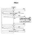
- FIG. 4 shows a flowchart of an energy scanning process using the first smoothing process.
- the control unit 10 sets a variable "n” to 11 (step S11).
- the variable "n” indicates the channel number of the wireless channel whose electric field intensity is to be detected (a channel to be detected).
- the control unit 10 determines whether the detection timing signal is input from the timer 13 or not (step S12). In the case where the detection timing signal is not input (NO in step S12), the control unit 10 returns to the process of step S12.
- control unit 10 determines whether the variable "n" is equal to the channel number "a" of the use channel or not (step S13).
- control unit 10 causes the detection unit 15 to detect (scan) the electric field intensity of the wireless channel of the channel number indicated by the variable "n” (step S14), sets the value detected by the detection unit 15 as electric field intensity C[n] of the channel number indicated by the variable "n”, and writes the detected value into the electric field intensity table (step S15).
- control unit 10 sets a new variable "n” by adding 1 to the variable "n” (step S16).
- the control unit 10 determines whether the value (27 in this case) obtained by adding 1 to the number (26 in this case) of the largest wireless channel among wireless channels which can be set is equal to the variable "n” or not (step S17).
- control unit 10 returns to the process in step S13.
- control unit 10 executes the first smoothing process, sets the calculated value of the electric field intensity of the use channel "a” as the estimated electric field intensity C[a] of the use channel, writes it in the electric field intensity table (step S18), and returns to the process in step S11.
- the electric field intensity C[a] of the use channel "a” is calculated based on electric field intensities C[a-1] and C[a+1] written in the electric field intensity table and the following formula (1).
- the electric field intensity C[a-1] is the electric field intensity of the wireless channel a-1 below the use channel.
- the electric field intensity C[a+1] is the electric field intensity of the wireless channel a+1 above the use channel.
- C a C ⁇ a - 1 + C ⁇ a + 1 / 2
- the average value of the electric field intensities of two wireless channels below and above the use channel can be obtained as an estimated value of the electric field intensity of the use channel "a".
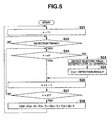
- FIG. 5 shows a flowchart of an energy scanning process using the second smoothing process. Since processes in steps S21 to S27 shown in FIG. 5 are similar to those in steps S11 to S17 shown in FIG. 4 , the description thereof will not be repeated.
- control unit 10 executes the second smoothing process, sets the calculated value of the electric field intensity of the use channel "a” as the estimated electric field intensity C[a] of the use channel, writes it in the electric field intensity table (step S28), and returns to the process of step S21.
- the electric field intensity C[a] of the use channel "a” is calculated based on electric field intensities C[a-2], C[a-1], C[a+1], and C[a+2] written in the electric field intensity table and the following formula (2).
- the electric field intensities C[a-2] and C[a-1] are the electric field intensities of a plurality of (two, in this case) wireless channels a-2 and a-1 below the use channel.
- the electric field intensities C[a+1] and C[a+2] are the electric field intensities of a plurality of (two, in this case) wireless channels a+1 and a+2 above the use channel.
- C a C ⁇ a - 2 + C ⁇ a - 1 + C ⁇ a + 1 + C ⁇ a + 2 / 4
- the second smoothing process without detecting the electric field intensity of the wireless channel (use channel "a") used in the wireless transmission/reception unit 14, the average value of the electric field intensities of a plurality of preset wireless channels below and above the use channel can be obtained as an estimated value of the electric field intensity of the use channel "a".
- FIG. 6 shows a flowchart of an energy scanning process in which the third smoothing process is set. Since processes in steps S31 to S37 shown in FIG. 6 are similar to those in steps S11 to S17 shown in FIG. 4 , the description thereof will not be repeated.
- control unit 10 executes the third smoothing process, sets the calculated value of the electric field intensity of the use channel "a” as the estimated electric field intensity C[a] of the use channel, writes it in the electric field intensity table (step S38), and returns to the process of step S31.
- the electric field intensity C[a] of the use channel "a” is calculated based on electric field intensities C[a-2], C[a-1], C[a+1], and C[a+2] written in the electric field intensity table, weights x, y, z, and w which are set on the electric field intensities C[a-2], C[a-1], C[a+1], and C[a+2], respectively, and a weighted average calculating formula shown as the following formula (3).
- the electric field intensities C[a-2] and C[a-1] are the electric field intensities of a plurality of (two, in this case) wireless channels a-2 and a-1 below the use channel.
- the electric field intensities C[a+1] and C[a+2] are the electric field intensities of a plurality of (two, in this case) wireless channels a+1 and a+2 above the use channel.
- C a x ⁇ C ⁇ a - 2 + y ⁇ C ⁇ a - 1 + z ⁇ C ⁇ a + 1 + w ⁇ C ⁇ a + 2 / x + y + z + w
- the weights w, y, z, and w may be weights which increase toward the use channel, or weights which are set according to the electric field intensities of the wireless channels.
- the third smoothing process without detecting the electric field intensity of the wireless channel (use channel "a") used in the wireless transmission/reception unit 14, the weighted average value of the electric field intensities of a plurality of preset wireless channels below and above the use channel can be obtained as an estimated value of the electric field intensity of the use channel.
- the value calculated by performing the smoothing processes in the frequency direction on the electric field intensity of the wireless channel whose electric field intensity is detected by the detection unit 15 can be obtained as the estimated value of the electric field intensity of the use channel.
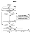
- FIG. 7 shows a flowchart of an energy scanning process using the first comparing process. Since the processes in steps S41 to S47 shown in FIG. 7 are similar to those of steps S11 to S17 shown in FIG. 4 , the description thereof will not be repeated.
- control unit 10 executes the first comparing process (step S48), sets the comparison result as the estimated electric field intensity C[a] of the use channel, writes it in the electric field intensity table (step S49 or S50), and returns to the process in step S41.
- step S48 the electric field intensities C[a-1] and C[a+1] written in the electric field intensity table are compared with each other to determine whether the electric field intensity C[a-1] is higher than the electric field intensity C[a+1] or not.
- the electric field intensity C[a-1] is the electric field intensity of the wireless channel a-1 below the use channel.
- the electric field intensity C[a+1] is the electric field intensity of the wireless channel a+1 above the use channel.
- the electric field intensity C[a-1] is set as the estimated value of the electric field intensity of the use channel "a", and the set value is written as the electric field intensity C[a] of the use channel "a" into the electric field intensity table (step S49).
- the electric field intensity C[a-1] is equal to or lower than the electric field intensity C[a+1] (NO in step S48)
- the electric field intensity C[a+1] is set as the estimated value of the electric field intensity of the use channel "a"
- the set value is written as the electric field intensity C[a] of the use channel into the electric field intensity table (step S50).
- the higher one of the electric field intensities of two wireless channels below and above the use channel can be set as an estimated value of the electric field intensity of the use channel "a".
- FIG. 8 shows a flowchart of an energy scanning process in which the second comparing process is set. Since the processes in steps S51 to S57 shown in FIG. 8 are similar to those of steps S11 to S17 shown in FIG. 4 , the description thereof will not be repeated.
- control unit 10 executes the second comparing process, sets the comparison result "a" as the estimated electric field intensity C[a] of the use channel, writes it in the electric field intensity table (step S58), and returns to the process in step S51.
- the electric field intensities C[a-2], C[a-1], C[a+1], and C[a+2] written in the electric field intensity table are compared with each other to select the highest electric field intensity.
- the selected electric field intensity is set as the estimated value of the electric field intensity of the use channel "a”, and the set value is written as the electric field intensity C[a] of the use channel "a" into the electric field intensity table.
- the electric field intensities C[a-2] and C[a-1] are electric field intensities of two wireless channels a-2 and a-1 below the use channel.
- the electric field intensities C[a+1] and C[a+2] are electric field intensities of two wireless channels a+1 and a+2 above the use channel.
- the second comparing process without detecting the electric field intensity of the wireless channel (use channel "a") used in the wireless transmission/reception unit 14, the highest one of the electric field intensities of a plurality of preset wireless channels below and above the use channel can be obtained as an estimated value of the electric field intensity of the use channel "a".
- the present invention is not limited to the example.
- three or more wireless channels below and above the use channel may be used.
- the number of wireless channels below the use channel and that of wireless channels above the use channel are the same, the invention is not limited to the case.
- the estimated value of the electric field intensity of the use channel can be obtained based on the electric field intensities of the wireless channels except for the wireless channel (use channel) used in the wireless transmission/reception unit 14. Consequently, even during execution of the data transmitting/receiving process in the wireless transmission/reception unit 14, without detecting the electric field intensity of the use channel, the estimated value of the electric field intensity of the wireless channel can be obtained.
- the communication state of the use channel can be grasped.
- the communication environment of the data transmitting/receiving process in the wireless transmission/reception unit 14 can be maintained excellent.
- the wireless communication apparatus and the wireless communication method capable of grasping the electric field intensity of a wireless channel without detecting the electric field intensity of the wireless channel being used can be provided.
Landscapes
- Engineering & Computer Science (AREA)
- Physics & Mathematics (AREA)
- Electromagnetism (AREA)
- Computer Networks & Wireless Communication (AREA)
- Signal Processing (AREA)
- Quality & Reliability (AREA)
- Mobile Radio Communication Systems (AREA)
Abstract
Description
- The present invention relates generally to a wireless communication apparatus and a wireless communication method for detecting an electric field intensity of a wireless channel.
- In recent years, for example, in a wireless communication system specified in, for example, IEEE 802.15.4, a preset wireless frequency band is divided into a plurality of wireless channels in predetermined band widths so as not to overlap each other. Any one of the wireless channels is selected, and wireless communication between ratio communication apparatuses is performed in the selected wireless channel.
- In such a wireless communication system, there is a wireless communication apparatus having a function of transmitting/receiving data and a function of detecting the electric field intensity of a wireless channel for transmitting/receiving the data in order to continuously maintain good communication environments.
- For example, Jpn. Pat. Appln. KOKAI Publication No.
2003-151062 - To address the problem, there is a wireless communication apparatus comprising two wireless units. One of the wireless units is used for data transmission/reception, and the other wireless unit is used for detecting the electric field intensities of a plurality of wireless channels in order to find a wireless channel whose communication state is excellent. In such a wireless communication apparatus, while one of the wireless units transmits/receives data, the electric field intensity of the wireless channel used for transmitting/receiving data is detected. Consequently, it becomes unclear whether the detection result of the wireless channel used is a result of detecting the electric field intensity accompanying transmission/reception of data, a result of detecting the electric field intensity of an interference wave, or a result of detection of both of the electric field intensities. That is, there is a problem in that the electric field intensity for determining the communication state of the wireless channel used cannot be detected.
- Further, it is considered that when one of the wireless units and the other wireless unit are synchronized and one of the wireless units is transmitting/receiving data, the electric field intensity of the wireless channel used is not detected. However, the data transmitting/receiving timing occurs at random. Consequently, there are problems in that the electric field intensity of the wireless channel being used cannot be periodically detected, and the detection result cannot be evaluated equivalent to the detection results of the electric field intensities of other wireless channels.
- An object of the present invention is to obtain the electric field intensity of a wireless channel used without detecting the electric field intensity of the wireless channel.
- According to an embodiment of the present invention, a wireless communication apparatus comprises a communication unit configured to wirelessly communicate with another wireless communication apparatus using a first wireless channel; a detection unit configured to detect electric field intensities of wireless channels except for the first wireless channel; and a control unit configured to calculate an electric field intensity of the first wireless channel based on the electric field intensities of the wireless channels detected by the detection unit.
- According to another embodiment of the present invention, a wireless communication method for a wireless communication apparatus comprising a communication unit configured to wirelessly communicate with another wireless communication apparatus using a first wireless channel, the method comprises detecting electric field intensities of wireless channels except for the first wireless channel; and calculating an electric field intensity of the first wireless channel based on the electric field intensities of the wireless channels.
- The invention can be more fully understood from the following detailed description when taken in conjunction with the accompanying drawings, in which:
-
FIG. 1 is a schematic configuration diagram of a wireless communication system according to an embodiment of the invention. -
FIG. 2 is a schematic configuration diagram of a wireless relay device according to the embodiment. -
FIG. 3 is a flowchart of data transmitting/receiving process executed in the wireless relay device according to the embodiment. -
FIG. 4 is a flowchart of energy scanning process using first smoothing process according to the embodiment. -
FIG. 5 is a flowchart of energy scanning process using second smoothing process according to the embodiment. -
FIG. 6 is a flowchart of energy scanning process using third smoothing process according to an embodiment of the invention. -
FIG. 7 is a flowchart of energy scanning process using first comparing process according to an embodiment of the invention. -
FIG. 8 is a flowchart of energy scanning process using second comparing process according to an embodiment of the invention. - An embodiment of the present invention will be described in detail below with reference to the drawings. The invention is not limited to the embodiment. Terms of the invention are not limited to those used in the embodiment.
- First, the configuration will be described.
-
FIG. 1 is a schematic configuration diagram of a wireless communication system A in the embodiment. - As shown in
FIG. 1 , the wireless communication system A comprises awireless relay device 1 connected to another wireless relay device or external apparatus via a communication network N, and a plurality ofwireless terminal devices 2 connected to thewireless relay device 1 via wireless waves. - In the wireless communication system A, any one of a plurality of wireless channels obtained by dividing a preset frequency band into a plurality of pieces so as not to overlap each other is used, and wireless communication is performed between the
wireless relay device 1 and theratio terminal device 2. For example, a frequency band of 2.4 GHz is divided into a total of 16 channels ofchannel 11 to channel 26. By using any one of the wireless channels, communication is performed between thewireless relay device 1 and thewireless terminal device 2. - In the following, the
wireless relay device 1, the external apparatus, and thewireless terminal device 2 will be also collectively called wireless communication apparatuses. -
FIG. 2 is a schematic configuration diagram of thewireless relay device 1. - As shown in
FIG. 2 , thewireless relay device 1 comprises acontrol unit 10, astorage unit 11, aterminal information memory 12, atimer 13, a wireless transmission/reception unit 14, adetection unit 15, a switch unit (SW) 16, an interface (I/F)unit 17, abuffer memory 18, anantenna 19, and the like which are electrically connected to one another. - The
control unit 10 comprises a central processing unit (CPU), a read only memory (ROM), a random access memory (RAM), and the like. Thecontrol unit 10 reads a designated program, table, or data from various programs, various tables, data, and the like stored in thestorage unit 11 and theterminal information memory 12, expands it in a work area in the RAM, thestorage unit 11, or theterminal information memory 12, executes various processes in cooperation with the program, stores the process result in a predetermined region in the RAM, thestorage unit 11, or theterminal information memory 12, and instructs the units in thewireless relay device 1 to generally control overall operation of thewireless relay device 1. - The
control unit 10 selects and determines a wireless channel having low interference wave level and excellent wave condition in the wireless frequency band which is divided into a plurality of wireless channels as a wireless channel (use channel) to be used in the wireless transmission/reception unit 14 at the time of performing wireless communication with thewireless terminal device 2. To select the use channel, thecontrol unit 10 periodically executes, by thedetection unit 15, energy scanning process of detecting the electric field intensities of the plurality of wireless channels which can be selected. The energy scanning process is executed independently of data transmitting/receiving process executed by the wireless transmission/reception unit 14. - In the energy scanning process of the embodiment, the electric field intensities of the wireless channels except for the wireless channel (use channel) which is used in the wireless transmission/
reception unit 14 in the plurality of wireless channels are detected by thedetection unit 15. Based on the electric field intensities of the wireless channels detected by thedetection unit 15, an estimated value of the electric field intensity of the use channel is calculated. - As processes of calculating the estimated value of the electric field intensity of the use channel in the embodiment, there are a smoothing process and a comparing process. Further, the smoothing process includes three kinds of processes, and the comparing process includes two kinds of processes. Any one of the processes is preset as the process of calculating the estimated value.
- In the smoothing process, any of the following first to third smoothing processes is performed in the frequency directions of the wireless channels on the electric fields of the wireless channels whose electric field intensities are detected by the
detection unit 15 except for the use channel, and the value calculated by the process becomes the estimated value of the electric field intensity of the use channel. - In the first smoothing process, an average value of the electric field intensities of two wireless channels existing below and above the use channel is calculated. For example, when the use channel is channel 20, the average value of the electric field intensities of
channels 19 and 21 is calculated as the estimated value of the electric field intensity of the use channel (channel 20). It is assumed that the smaller the number of a channel, the lower the frequency. - In the second smoothing process, an average value of the electric field intensities of a plurality of preset wireless channels existing below and above the use channel is calculated. For example, when the use channel is channel 20 and the plurality of preset wireless channels are two
wireless channels channels - In the third smoothing process, a weighted average value of the electric field intensities of a plurality of preset wireless channels below and above the use channel is calculated. For example, when the use channel is channel 20, the plurality of preset wireless channels are two
wireless channels channels channels - The comparing process includes a first comparing process and a second comparing process.
- In the first comparing process, the electric field intensities of two wireless channels below and above the use channel are compared, and the higher electric field intensity of the wireless channel is used as the estimated value of the electric field intensity of the use channel. For example, when the use channel is channel 20, the higher one of the electric field intensities of
channels 19 and 21 is used as the estimated value of the electric field intensity of the use channel (channel 20). - In the second comparing process, the highest one of electric field intensities of a plurality of preset wireless channels existing below and above the use channel is calculated as the estimated value of the electric field intensity of a wireless channel used in the wireless transmission/
reception unit 14. For example, when the use channel is channel 20 and the plurality of preset wireless channels are twowireless channels channels - The
storage unit 11 is an electrically erasable and programmable nonvolatile memory such as a magnetic or optical recording medium or a semiconductor memory, and is fixedly or detachably attached in thewireless relay device 1. In thestorage unit 11, programs for processes in the embodiment executed by thecontrol unit 10, various programs, and various tables, data, electric field intensity table, and the like used in the programs are stored. - Each time the energy scanning process is executed, electric field intensities detected for wireless channels except for the use channel and the estimated value of the electric field intensity of the use channel are overwritten in the electric field intensity table.
- The
terminal information memory 12 is an electrically erasable and programmable memory. In theterminal information memory 12, terminal information such as a node address unique to each of thewireless terminal devices 2 connected to thewireless relay device 1 is stored. - The
timer 13 counts the interval of timings (scan interval) of executing the energy scanning process and, for every scan interval, outputs a detection timing signal to thecontrol unit 10. - The wireless transmission/
reception unit 14 comprises a modulation circuit and an RF (Wireless Frequency) circuit, adjusts packet transmission power, constructs a packet by encoding data to be transmitted in accordance with an instruction from thecontrol unit 10, modulates the constructed packet, and transmits the packet to thewireless terminal device 2 via theantenna 19. The wireless transmission/reception unit 14 comprises a demodulating circuit and an RF circuit, adjusts packet reception sensitivity, demodulates and decodes the packet received via theantenna 19, and outputs data obtained by analyzing the decoded packet to thecontrol unit 10. - With the wireless transmission/
reception unit 14 and theantenna 19, a communication unit is realized which performs wireless communication with thewireless terminal device 2 as a wireless communication apparatus by using any one of a plurality of wireless channels. - The
detection unit 15 detects electric field intensity of each of the plurality of wireless channels via theantenna 19. - The
SW 16 is provided between the wireless transmission/reception unit 14 and thedetection unit 15 and theantenna 19 and switches between the units (the wireless transmission/reception unit 14 and the detection unit 15) to be connected to theantenna 19. - The I/
F unit 17 performs communication control for performing communication with the otherwireless relay devices 1 or external apparatuses connected via the communication network N by a predetermined communication method. - The
buffer memory 18 temporarily stores data received via the I/F unit 17. - The
wireless terminal device 2 comprises a control unit, a storage unit, a timer, a wireless transmission/reception unit, a detection unit, a switch unit, an antenna, and the like which are electrically connected, and performs wireless communication with thewireless relay device 1 by using any one of a plurality of wireless channels. - When it is necessary to newly find a wireless channel for performing wireless communication with the
wireless relay device 1 in the case where the communication state of the use channel deteriorates, thewireless terminal device 2 of the embodiment executes the energy scanning process like thewireless relay device 1 does. - Since the energy scanning process executed by the
wireless terminal device 2 is similar to the energy scanning process executed by thewireless relay device 1, illustration and description thereof will not be provided. Specifically, since thewireless terminal device 2 executes the energy scanning process like thewireless relay device 1 does, thewireless relay device 1 and thewireless terminal device 2 are realized as wireless communication apparatuses. - Next, the operation of the embodiment will be described.
-
FIG. 3 is a flowchart of data transmitting/receiving process executed by thewireless relay device 1. The process shown inFIG. 3 is executed in cooperation with thecontrol unit 10 and the other units in thewireless relay device 1 as needed while power is supplied to thewireless relay device 1. - The
control unit 10 determines whether there is data to be received by the wireless transmission/reception unit 14 via theantenna 19 or not (step S1). Stated another way, it is determined whether theantenna 19 receives data having a destination address of thewireless relay device 1. In the case where there is no data to be received (NO in step S1), thecontrol unit 10 advances to process in step S3. In the case where there is data to be received (YES in step S1), thecontrol unit 10 executes a process of receiving the data to be received (step S2). - After step S2 or after NO in step S1, the
control unit 10 determines whether there is data to be transmitted from the wireless transmission/reception unit 14 or not (step S3). In the case where there is no data to be transmitted (NO in step S3), thecontrol unit 10 advances to the process in step S5. In the case where there is data to be transmitted (YES in step S3), thecontrol unit 10 executes a process of transmitting the data to be transmitted (step S4). - After step S4 or after NO in step S3, the
control unit 10 reads an electric field intensity table from the storage unit 11 (step S5) and determines whether the communication state of a wireless channel (use channel) used by the wireless transmission/reception unit 14 for performing wireless communication with thewireless terminal device 2 at present deteriorates or not (step S6). - In step S6, the electric field intensity table is referred to, and it is determined whether the electric field intensity of the use channel is larger than a preset threshold or not. In the case where the electric field intensity of the use channel is larger than the threshold, it is determined that the communication state deteriorates.
- In the case where the communication state of the use channel deteriorates (YES in step S6), the
control unit 10 changes the use channel to a wireless channel with a good communication state, that is, a wireless channel having relatively low electric field intensity (although a wireless channel having the lowest electric field intensity is preferable, a wireless channel having relatively low electric field intensity (lower than the electric field intensity of the use channel) is sufficient) with reference to the electric field intensity table (step S7) and returns to the process in step S1. - In the case where the communication state of the use channel does not deteriorate (NO in step S6), the
control unit 10 executes a communication quality evaluating process (step S8). - In the communication quality evaluating process executed in step S8, it is determined whether the reception rate of an ACK signal or the packet error occurrence rate for data transmitted by using a use channel is equal to or higher than a preset rate or not. Based on the determination result, it is evaluated whether the communication quality of the use channel deteriorates or not.
- After step S8, the
control unit 10 determines whether the communication quality of the use channel deteriorates or not (step S9). In the case where the communication quality of the use channel deteriorates (YES in step S9), thecontrol unit 10 advances to the process in step S7. In the case where the communication quality of the use channel does not deteriorate (NO in step S9), thecontrol unit 10 advances to the process in step S1. -
FIGS. 4 to 8 show flowcharts of the energy scanning process. The processes shown inFIGS. 4 to 8 are executed by cooperation between thecontrol unit 10 and the other units in thewireless relay device 1 as needed while power is supplied to thewireless relay device 1. -
FIG. 4 shows a flowchart of an energy scanning process using the first smoothing process. Thecontrol unit 10 sets a variable "n" to 11 (step S11). The variable "n" indicates the channel number of the wireless channel whose electric field intensity is to be detected (a channel to be detected). - The
control unit 10 determines whether the detection timing signal is input from thetimer 13 or not (step S12). In the case where the detection timing signal is not input (NO in step S12), thecontrol unit 10 returns to the process of step S12. - In the case where the detection timing signal is input (YES in step S12), the
control unit 10 determines whether the variable "n" is equal to the channel number "a" of the use channel or not (step S13). - In the case where the variable "n" is not equal to the channel number "a" of the use channel (NO in step S13), the
control unit 10 causes thedetection unit 15 to detect (scan) the electric field intensity of the wireless channel of the channel number indicated by the variable "n" (step S14), sets the value detected by thedetection unit 15 as electric field intensity C[n] of the channel number indicated by the variable "n", and writes the detected value into the electric field intensity table (step S15). - In the case where the variable "n" is equal to the channel number "a" of the use channel (YES in step S13) or after step S15, the
control unit 10 sets a new variable "n" by adding 1 to the variable "n" (step S16). Thecontrol unit 10 determines whether the value (27 in this case) obtained by adding 1 to the number (26 in this case) of the largest wireless channel among wireless channels which can be set is equal to the variable "n" or not (step S17). - In the case where the value (27 in this case) obtained by adding 1 to the number (26 in this case) of the largest wireless channel among wireless channels which can be set is not equal to the variable "n" (NO in step S17), the
control unit 10 returns to the process in step S13. - In the case where the value (27 in this case) obtained by adding 1 to the number (26 in this case) of the largest wireless channel among wireless channels which can be set is equal to the variable "n" (YES in step S17), the
control unit 10 executes the first smoothing process, sets the calculated value of the electric field intensity of the use channel "a" as the estimated electric field intensity C[a] of the use channel, writes it in the electric field intensity table (step S18), and returns to the process in step S11. - In the first smoothing process executed in step S18, the electric field intensity C[a] of the use channel "a" is calculated based on electric field intensities C[a-1] and C[a+1] written in the electric field intensity table and the following formula (1).
- The electric field intensity C[a-1] is the electric field intensity of the wireless channel a-1 below the use channel. The electric field intensity C[a+1] is the electric field intensity of the wireless channel a+1 above the use channel.

- As described above, by the first smoothing process, without detecting the electric field intensity of the wireless channel (use channel "a") used in the wireless transmission/
reception unit 14, the average value of the electric field intensities of two wireless channels below and above the use channel can be obtained as an estimated value of the electric field intensity of the use channel "a". -
FIG. 5 shows a flowchart of an energy scanning process using the second smoothing process. Since processes in steps S21 to S27 shown inFIG. 5 are similar to those in steps S11 to S17 shown inFIG. 4 , the description thereof will not be repeated. - When the value (27 in this case) obtained by adding 1 to the number (26 in this case) of the largest wireless channel among the wireless channels which can be set is equal to the variable "n" (YES in step S27), the
control unit 10 executes the second smoothing process, sets the calculated value of the electric field intensity of the use channel "a" as the estimated electric field intensity C[a] of the use channel, writes it in the electric field intensity table (step S28), and returns to the process of step S21. - In the second smoothing process executed in step S28, the electric field intensity C[a] of the use channel "a" is calculated based on electric field intensities C[a-2], C[a-1], C[a+1], and C[a+2] written in the electric field intensity table and the following formula (2).
- The electric field intensities C[a-2] and C[a-1] are the electric field intensities of a plurality of (two, in this case) wireless channels a-2 and a-1 below the use channel. The electric field intensities C[a+1] and C[a+2] are the electric field intensities of a plurality of (two, in this case) wireless channels a+1 and a+2 above the use channel.

- As described above, by the second smoothing process, without detecting the electric field intensity of the wireless channel (use channel "a") used in the wireless transmission/
reception unit 14, the average value of the electric field intensities of a plurality of preset wireless channels below and above the use channel can be obtained as an estimated value of the electric field intensity of the use channel "a". -
FIG. 6 shows a flowchart of an energy scanning process in which the third smoothing process is set. Since processes in steps S31 to S37 shown inFIG. 6 are similar to those in steps S11 to S17 shown inFIG. 4 , the description thereof will not be repeated. - When the value (27 in this case) obtained by adding 1 to the number (26 in this case) of the largest wireless channel among the wireless channels which can be set is equal to the variable "n" (YES in step S37), the
control unit 10 executes the third smoothing process, sets the calculated value of the electric field intensity of the use channel "a" as the estimated electric field intensity C[a] of the use channel, writes it in the electric field intensity table (step S38), and returns to the process of step S31. - In the third smoothing process executed in step S38, the electric field intensity C[a] of the use channel "a" is calculated based on electric field intensities C[a-2], C[a-1], C[a+1], and C[a+2] written in the electric field intensity table, weights x, y, z, and w which are set on the electric field intensities C[a-2], C[a-1], C[a+1], and C[a+2], respectively, and a weighted average calculating formula shown as the following formula (3).
- The electric field intensities C[a-2] and C[a-1] are the electric field intensities of a plurality of (two, in this case) wireless channels a-2 and a-1 below the use channel. The electric field intensities C[a+1] and C[a+2] are the electric field intensities of a plurality of (two, in this case) wireless channels a+1 and a+2 above the use channel.

- The weights w, y, z, and w may be weights which increase toward the use channel, or weights which are set according to the electric field intensities of the wireless channels.
- As described above, by the third smoothing process, without detecting the electric field intensity of the wireless channel (use channel "a") used in the wireless transmission/
reception unit 14, the weighted average value of the electric field intensities of a plurality of preset wireless channels below and above the use channel can be obtained as an estimated value of the electric field intensity of the use channel. - Therefore, by the first to third smoothing processes, the value calculated by performing the smoothing processes in the frequency direction on the electric field intensity of the wireless channel whose electric field intensity is detected by the
detection unit 15 can be obtained as the estimated value of the electric field intensity of the use channel. -
FIG. 7 shows a flowchart of an energy scanning process using the first comparing process. Since the processes in steps S41 to S47 shown inFIG. 7 are similar to those of steps S11 to S17 shown inFIG. 4 , the description thereof will not be repeated. - In the case where the value (27 in this case) obtained by adding 1 to the number (26 in this case) of the largest wireless channel among wireless channels which can be set is equal to the variable "n" (YES in step S47), the
control unit 10 executes the first comparing process (step S48), sets the comparison result as the estimated electric field intensity C[a] of the use channel, writes it in the electric field intensity table (step S49 or S50), and returns to the process in step S41. - In the first comparing process executed in step S48, the electric field intensities C[a-1] and C[a+1] written in the electric field intensity table are compared with each other to determine whether the electric field intensity C[a-1] is higher than the electric field intensity C[a+1] or not.
- The electric field intensity C[a-1] is the electric field intensity of the wireless channel a-1 below the use channel. The electric field intensity C[a+1] is the electric field intensity of the wireless channel a+1 above the use channel.
- When the electric field intensity C[a-1] is higher than the electric field intensity C[a+1] (YES in step S48), the electric field intensity C[a-1] is set as the estimated value of the electric field intensity of the use channel "a", and the set value is written as the electric field intensity C[a] of the use channel "a" into the electric field intensity table (step S49).
- When the electric field intensity C[a-1] is equal to or lower than the electric field intensity C[a+1] (NO in step S48), the electric field intensity C[a+1] is set as the estimated value of the electric field intensity of the use channel "a", and the set value is written as the electric field intensity C[a] of the use channel into the electric field intensity table (step S50).
- As described above, by the first comparing process, without detecting the electric field intensity of the wireless channel (use channel "a") used in the wireless transmission/
reception unit 14, the higher one of the electric field intensities of two wireless channels below and above the use channel can be set as an estimated value of the electric field intensity of the use channel "a". -
FIG. 8 shows a flowchart of an energy scanning process in which the second comparing process is set. Since the processes in steps S51 to S57 shown inFIG. 8 are similar to those of steps S11 to S17 shown inFIG. 4 , the description thereof will not be repeated. - In the case where the value (27 in this case) obtained by adding 1 to the number (26 in this case) of the largest wireless channel among wireless channels which can be set is equal to the variable "n" (YES in step S57), the
control unit 10 executes the second comparing process, sets the comparison result "a" as the estimated electric field intensity C[a] of the use channel, writes it in the electric field intensity table (step S58), and returns to the process in step S51. - In the second comparing process executed in step S58, the electric field intensities C[a-2], C[a-1], C[a+1], and C[a+2] written in the electric field intensity table are compared with each other to select the highest electric field intensity. The selected electric field intensity is set as the estimated value of the electric field intensity of the use channel "a", and the set value is written as the electric field intensity C[a] of the use channel "a" into the electric field intensity table.
- The electric field intensities C[a-2] and C[a-1] are electric field intensities of two wireless channels a-2 and a-1 below the use channel. The electric field intensities C[a+1] and C[a+2] are electric field intensities of two wireless channels a+1 and a+2 above the use channel.
- As described above, by the second comparing process, without detecting the electric field intensity of the wireless channel (use channel "a") used in the wireless transmission/
reception unit 14, the highest one of the electric field intensities of a plurality of preset wireless channels below and above the use channel can be obtained as an estimated value of the electric field intensity of the use channel "a". - Although the example of using a total of four wireless channels of two wireless channels and two wireless channels below and above the use channel as the plurality of preset wireless channels has been described in the embodiment, the present invention is not limited to the example. For example, three or more wireless channels below and above the use channel may be used. Although the number of wireless channels below the use channel and that of wireless channels above the use channel are the same, the invention is not limited to the case.
- As described above, according to the embodiment, the estimated value of the electric field intensity of the use channel can be obtained based on the electric field intensities of the wireless channels except for the wireless channel (use channel) used in the wireless transmission/
reception unit 14. Consequently, even during execution of the data transmitting/receiving process in the wireless transmission/reception unit 14, without detecting the electric field intensity of the use channel, the estimated value of the electric field intensity of the wireless channel can be obtained. - Therefore, based on the estimated value of the electric field intensity of the use channel, the communication state of the use channel can be grasped. Before the communication quality of the use channel deteriorates, by changing the use channel to a wireless channel of good communication quality, the communication environment of the data transmitting/receiving process in the wireless transmission/
reception unit 14 can be maintained excellent. - That is, according to the embodiment, the wireless communication apparatus and the wireless communication method capable of grasping the electric field intensity of a wireless channel without detecting the electric field intensity of the wireless channel being used can be provided.
Claims (14)
- A wireless communication apparatus characterized by comprising:a communication unit (14) configured to wirelessly communicate with another wireless communication apparatus using a first wireless channel;a detection unit (15) configured to detect electric field intensities of wireless channels except for the first wireless channel; anda control unit (10) configured to calculate an electric field intensity of the first wireless channel based on the electric field intensities of the wireless channels detected by the detection unit (15).
- The wireless communication apparatus according to claim 1, characterized in that the communication unit (14) is configured to wirelessly communicate with another wireless communication apparatus using another wireless channel whose electric field intensity is lower than the electric field intensity of the first wireless channel when a communication state of the first wireless channel deteriorates.
- The wireless communication apparatus according to claim 1, characterized in that the control unit (10) is configured to calculate an average value of electric field intensities of two wireless channels below and above the first wireless channel.
- The wireless communication apparatus according to claim 1, characterized in that the control unit (10) is configured to calculate an average value of electric field intensities of more than two wireless channels below and above the first wireless channel.
- The wireless communication apparatus according to claim 1, characterized in that the control unit (10) is configured to calculate a weighted average value of electric field intensities of wireless channels below and above the first wireless channel.
- The wireless communication apparatus according to claim 1, characterized in that the control unit (10) is configured to obtain higher one of electric field intensities of wireless channels below and above the first wireless channel.
- The wireless communication apparatus according to claim 1, characterized in that the control unit (10) is configured to obtain a highest electric field intensity among electric field intensities of wireless channels below and above the first wireless channel.
- A wireless communication method for a wireless communication apparatus comprising a communication unit (14) configured to wirelessly communicate with another wireless communication apparatus using a first wireless channel, the method characterized by comprising:detecting electric field intensities of wireless channels except for the first wireless channel; andcalculating an electric field intensity of the first wireless channel based on the electric field intensities of the wireless channels.
- The wireless communication method according to claim 8, characterized by further comprising changing the first wireless channel to another wireless channel whose electric field intensity is lower than the electric field intensity of the first wireless channel when a communication state of the first wireless channel deteriorates.
- The wireless communication method according to claim 8, characterized in that the calculating comprises calculating an average value of electric field intensities of two wireless channels below and above the first wireless channel.
- The wireless communication method according to claim 8, characterized in that the calculating comprises calculating an average value of electric field intensities of more than two wireless channels below and above the first wireless channel.
- The wireless communication method according to claim 8, characterized in that the calculating comprises calculating a weighted average value of electric field intensities of wireless channels below and above the first wireless channel.
- The wireless communication method according to claim 8, characterized in that the calculating comprises obtaining higher one of electric field intensities of wireless channels below and above the first wireless channel.
- The wireless communication method according to claim 8, characterized in that the calculating comprises obtaining a highest electric field intensity among electric field intensities of wireless channels below and above the first wireless channel.
Applications Claiming Priority (1)
| Application Number | Priority Date | Filing Date | Title |
|---|---|---|---|
| JP2009155884A JP4766158B2 (en) | 2009-06-30 | 2009-06-30 | Wireless communication apparatus and wireless communication method |
Publications (3)
| Publication Number | Publication Date |
|---|---|
| EP2278723A2 true EP2278723A2 (en) | 2011-01-26 |
| EP2278723A3 EP2278723A3 (en) | 2014-06-25 |
| EP2278723B1 EP2278723B1 (en) | 2016-06-29 |
Family
ID=42790832
Family Applications (1)
| Application Number | Title | Priority Date | Filing Date |
|---|---|---|---|
| EP10164419.3A Not-in-force EP2278723B1 (en) | 2009-06-30 | 2010-05-31 | Wireless communication apparatus and wireless communication method for detecting electric field intensity of wirelss channel |
Country Status (5)
| Country | Link |
|---|---|
| US (1) | US8818286B2 (en) |
| EP (1) | EP2278723B1 (en) |
| JP (1) | JP4766158B2 (en) |
| CN (1) | CN101938759B (en) |
| TW (1) | TWI528743B (en) |
Families Citing this family (3)
| Publication number | Priority date | Publication date | Assignee | Title |
|---|---|---|---|---|
| US20120009363A1 (en) | 2010-07-07 | 2012-01-12 | Hideto Kiyama | Recording sheet for wet electrophotography |
| US9992722B2 (en) * | 2015-12-14 | 2018-06-05 | Huawei Technologies Canada Co., Ltd. | Reconfigurable multi-mode and multi-bands radio architecture and transceiver |
| JP2023096367A (en) * | 2021-12-27 | 2023-07-07 | Necフィールディング株式会社 | Radio wave condition prediction system, method and program |
Citations (1)
| Publication number | Priority date | Publication date | Assignee | Title |
|---|---|---|---|---|
| JP2003151062A (en) | 2001-11-08 | 2003-05-23 | Sharp Corp | Wireless telemeter device and wireless telemeter system |
Family Cites Families (18)
| Publication number | Priority date | Publication date | Assignee | Title |
|---|---|---|---|---|
| JPH01177223A (en) * | 1988-01-05 | 1989-07-13 | Toshiba Corp | Movable radio communication equipment |
| JP2719619B2 (en) * | 1989-11-28 | 1998-02-25 | 日本電信電話株式会社 | Mobile communication channel assignment control method |
| JP3043171B2 (en) * | 1992-02-25 | 2000-05-22 | 富士通株式会社 | Control channel monitor method |
| JPH0998465A (en) * | 1995-09-29 | 1997-04-08 | Nec Corp | Portable radio telephone control method and portable radio telephone set |
| JP3568102B2 (en) * | 1998-07-24 | 2004-09-22 | 松下電器産業株式会社 | Direct conversion receiver |
| GB9904348D0 (en) * | 1999-02-26 | 1999-04-21 | Koninkl Philips Electronics Nv | Wireless communication channel management |
| JP4654507B2 (en) | 2000-11-17 | 2011-03-23 | パナソニック株式会社 | access point |
| US7206840B2 (en) | 2001-05-11 | 2007-04-17 | Koninklike Philips Electronics N.V. | Dynamic frequency selection scheme for IEEE 802.11 WLANs |
| AU2003284444A1 (en) * | 2002-11-26 | 2004-06-18 | Matsushita Electric Industrial Co., Ltd. | Communication method, transmitter apparatus and receiver apparatus |
| JP2005020568A (en) * | 2003-06-27 | 2005-01-20 | Matsushita Electric Ind Co Ltd | Synchronization acquisition method and synchronization acquisition apparatus |
| KR100552238B1 (en) * | 2004-08-13 | 2006-02-17 | 주식회사 팬택 | Receive Level Correction Method in Mobile Communication Terminal |
| US7633901B2 (en) * | 2005-06-23 | 2009-12-15 | Autocell Laboratories, Inc. | Co-channel congestion method and apparatus |
| JP4742859B2 (en) * | 2005-12-27 | 2011-08-10 | 株式会社ケンウッド | Radio, control method and program |
| JP4795111B2 (en) | 2006-05-16 | 2011-10-19 | 京セラ株式会社 | Mobile communication terminal, radio station apparatus switching method, and radio station apparatus switching program |
| JP2008219364A (en) * | 2007-03-02 | 2008-09-18 | Hitachi Kokusai Electric Inc | Microwave relay receiver |
| JP4406435B2 (en) * | 2007-03-05 | 2010-01-27 | 株式会社日立製作所 | Radio interference prevention method in multi-hop wireless system, multi-hop radio system, relay station, radio interference avoidance method and program for relay station |
| JP2008227651A (en) * | 2007-03-09 | 2008-09-25 | Nec Corp | Received electric field strength correction system and received electric field strength correction method for portable terminal |
| US8447241B2 (en) * | 2008-05-26 | 2013-05-21 | Panasonic Corporation | Wireless communication apparatus |
-
2009
- 2009-06-30 JP JP2009155884A patent/JP4766158B2/en not_active Expired - Fee Related
-
2010
- 2010-05-31 EP EP10164419.3A patent/EP2278723B1/en not_active Not-in-force
- 2010-06-29 TW TW099121141A patent/TWI528743B/en active
- 2010-06-29 US US12/825,788 patent/US8818286B2/en active Active
- 2010-06-29 CN CN201010220498.4A patent/CN101938759B/en not_active Expired - Fee Related
Patent Citations (1)
| Publication number | Priority date | Publication date | Assignee | Title |
|---|---|---|---|---|
| JP2003151062A (en) | 2001-11-08 | 2003-05-23 | Sharp Corp | Wireless telemeter device and wireless telemeter system |
Also Published As
| Publication number | Publication date |
|---|---|
| TWI528743B (en) | 2016-04-01 |
| EP2278723B1 (en) | 2016-06-29 |
| US8818286B2 (en) | 2014-08-26 |
| JP4766158B2 (en) | 2011-09-07 |
| EP2278723A3 (en) | 2014-06-25 |
| TW201126933A (en) | 2011-08-01 |
| CN101938759B (en) | 2013-04-03 |
| US20100330905A1 (en) | 2010-12-30 |
| CN101938759A (en) | 2011-01-05 |
| JP2011015052A (en) | 2011-01-20 |
Similar Documents
| Publication | Publication Date | Title |
|---|---|---|
| US7149205B2 (en) | Interference detection method and interference avoidance system for wireless communication links | |
| KR101231399B1 (en) | Adaptive received power control method and apparatus for antenna wireless channel measurement equipments | |
| KR100669964B1 (en) | Method and apparatus for implementing smart antenna and diversity technology | |
| KR20020061164A (en) | Antenna diversity communication apparatus | |
| JP4547521B2 (en) | Communication equipment, antenna switching method, program | |
| US10333572B2 (en) | Antenna tuner control circuit, front-end circuit and communication device | |
| US20030152046A1 (en) | Communication apparatus, communication system and communication frequency setting method | |
| CN104954039A (en) | Impedance matching method and impedance matching system for antenna | |
| EP2278723B1 (en) | Wireless communication apparatus and wireless communication method for detecting electric field intensity of wirelss channel | |
| KR102796614B1 (en) | Operating method for communication device and signal processor included in the communication device | |
| CN112118059B (en) | Method for reducing spurious interference, communication equipment and readable storage medium | |
| CN102474756B (en) | Wireless base station receiving device and signal demodulation method and program used therein | |
| CN112399462B (en) | A communication device and a wireless communication method | |
| US20170339587A1 (en) | Wireless communication methods and apparatus | |
| KR102247162B1 (en) | Beam selection apparatus and method for selecting beam in a fixed beam terminal | |
| JP2011015051A (en) | Radio communication equipment and program | |
| EP2259633B1 (en) | Wireless communication device and wireless communication method for detecting field intensities of wireless channels | |
| JP5088433B2 (en) | Wireless communication apparatus and program | |
| KR101300986B1 (en) | Apparatus and method for selecting serving sector in a mobile communication system | |
| JP4777401B2 (en) | Radio base station and radio communication method | |
| JP6443753B2 (en) | Receiving device, wireless device, and program | |
| JPWO2005032184A1 (en) | Mobile station and base station search method | |
| JP4777394B2 (en) | Radio base station and radio communication method | |
| JPH11298938A (en) | Zone switching communication device | |
| JPS63234640A (en) | Radio channel selection system |
Legal Events
| Date | Code | Title | Description |
|---|---|---|---|
| PUAI | Public reference made under article 153(3) epc to a published international application that has entered the european phase |
Free format text: ORIGINAL CODE: 0009012 |
|
| 17P | Request for examination filed |
Effective date: 20100531 |
|
| AK | Designated contracting states |
Kind code of ref document: A2 Designated state(s): AL AT BE BG CH CY CZ DE DK EE ES FI FR GB GR HR HU IE IS IT LI LT LU LV MC MK MT NL NO PL PT RO SE SI SK SM TR |
|
| AX | Request for extension of the european patent |
Extension state: BA ME RS |
|
| PUAL | Search report despatched |
Free format text: ORIGINAL CODE: 0009013 |
|
| AK | Designated contracting states |
Kind code of ref document: A3 Designated state(s): AL AT BE BG CH CY CZ DE DK EE ES FI FR GB GR HR HU IE IS IT LI LT LU LV MC MK MT NL NO PL PT RO SE SI SK SM TR |
|
| AX | Request for extension of the european patent |
Extension state: BA ME RS |
|
| RIC1 | Information provided on ipc code assigned before grant |
Ipc: H04B 1/38 20060101AFI20140520BHEP Ipc: H04W 16/04 20090101ALI20140520BHEP Ipc: H04B 17/00 20060101ALI20140520BHEP |
|
| REG | Reference to a national code |
Ref country code: DE Ref legal event code: R079 Ref document number: 602010034247 Country of ref document: DE Free format text: PREVIOUS MAIN CLASS: H04B0001380000 Ipc: H04B0017318000 |
|
| GRAP | Despatch of communication of intention to grant a patent |
Free format text: ORIGINAL CODE: EPIDOSNIGR1 |
|
| RIC1 | Information provided on ipc code assigned before grant |
Ipc: H04B 17/382 20150101ALI20160114BHEP Ipc: H04B 17/318 20150101AFI20160114BHEP |
|
| INTG | Intention to grant announced |
Effective date: 20160127 |
|
| GRAS | Grant fee paid |
Free format text: ORIGINAL CODE: EPIDOSNIGR3 |
|
| GRAA | (expected) grant |
Free format text: ORIGINAL CODE: 0009210 |
|
| AK | Designated contracting states |
Kind code of ref document: B1 Designated state(s): AL AT BE BG CH CY CZ DE DK EE ES FI FR GB GR HR HU IE IS IT LI LT LU LV MC MK MT NL NO PL PT RO SE SI SK SM TR |
|
| REG | Reference to a national code |
Ref country code: GB Ref legal event code: FG4D |
|
| RIN1 | Information on inventor provided before grant (corrected) |
Inventor name: UEHARA, NAOTAKA Inventor name: AMAGAI, HITOSHI Inventor name: HANDA, TETSUYA Inventor name: NUNOKAWA, MASATO Inventor name: SHINOHARA, SUMITO Inventor name: MIZUNO, KIMIYASU Inventor name: KOGANE, TAKAYUKI Inventor name: AIBARA, TAKEHIRO |
|
| REG | Reference to a national code |
Ref country code: CH Ref legal event code: EP |
|
| REG | Reference to a national code |
Ref country code: AT Ref legal event code: REF Ref document number: 809826 Country of ref document: AT Kind code of ref document: T Effective date: 20160715 |
|
| REG | Reference to a national code |
Ref country code: IE Ref legal event code: FG4D |
|
| REG | Reference to a national code |
Ref country code: DE Ref legal event code: R096 Ref document number: 602010034247 Country of ref document: DE |
|
| REG | Reference to a national code |
Ref country code: LT Ref legal event code: MG4D |
|
| PG25 | Lapsed in a contracting state [announced via postgrant information from national office to epo] |
Ref country code: FI Free format text: LAPSE BECAUSE OF FAILURE TO SUBMIT A TRANSLATION OF THE DESCRIPTION OR TO PAY THE FEE WITHIN THE PRESCRIBED TIME-LIMIT Effective date: 20160629 Ref country code: NO Free format text: LAPSE BECAUSE OF FAILURE TO SUBMIT A TRANSLATION OF THE DESCRIPTION OR TO PAY THE FEE WITHIN THE PRESCRIBED TIME-LIMIT Effective date: 20160929 Ref country code: LT Free format text: LAPSE BECAUSE OF FAILURE TO SUBMIT A TRANSLATION OF THE DESCRIPTION OR TO PAY THE FEE WITHIN THE PRESCRIBED TIME-LIMIT Effective date: 20160629 |
|
| REG | Reference to a national code |
Ref country code: NL Ref legal event code: MP Effective date: 20160629 |
|
| PG25 | Lapsed in a contracting state [announced via postgrant information from national office to epo] |
Ref country code: SE Free format text: LAPSE BECAUSE OF FAILURE TO SUBMIT A TRANSLATION OF THE DESCRIPTION OR TO PAY THE FEE WITHIN THE PRESCRIBED TIME-LIMIT Effective date: 20160629 Ref country code: HR Free format text: LAPSE BECAUSE OF FAILURE TO SUBMIT A TRANSLATION OF THE DESCRIPTION OR TO PAY THE FEE WITHIN THE PRESCRIBED TIME-LIMIT Effective date: 20160629 Ref country code: GR Free format text: LAPSE BECAUSE OF FAILURE TO SUBMIT A TRANSLATION OF THE DESCRIPTION OR TO PAY THE FEE WITHIN THE PRESCRIBED TIME-LIMIT Effective date: 20160930 Ref country code: NL Free format text: LAPSE BECAUSE OF FAILURE TO SUBMIT A TRANSLATION OF THE DESCRIPTION OR TO PAY THE FEE WITHIN THE PRESCRIBED TIME-LIMIT Effective date: 20160629 Ref country code: LV Free format text: LAPSE BECAUSE OF FAILURE TO SUBMIT A TRANSLATION OF THE DESCRIPTION OR TO PAY THE FEE WITHIN THE PRESCRIBED TIME-LIMIT Effective date: 20160629 |
|
| REG | Reference to a national code |
Ref country code: AT Ref legal event code: MK05 Ref document number: 809826 Country of ref document: AT Kind code of ref document: T Effective date: 20160629 |
|
| PG25 | Lapsed in a contracting state [announced via postgrant information from national office to epo] |
Ref country code: IT Free format text: LAPSE BECAUSE OF FAILURE TO SUBMIT A TRANSLATION OF THE DESCRIPTION OR TO PAY THE FEE WITHIN THE PRESCRIBED TIME-LIMIT Effective date: 20160629 Ref country code: EE Free format text: LAPSE BECAUSE OF FAILURE TO SUBMIT A TRANSLATION OF THE DESCRIPTION OR TO PAY THE FEE WITHIN THE PRESCRIBED TIME-LIMIT Effective date: 20160629 Ref country code: IS Free format text: LAPSE BECAUSE OF FAILURE TO SUBMIT A TRANSLATION OF THE DESCRIPTION OR TO PAY THE FEE WITHIN THE PRESCRIBED TIME-LIMIT Effective date: 20161029 Ref country code: SK Free format text: LAPSE BECAUSE OF FAILURE TO SUBMIT A TRANSLATION OF THE DESCRIPTION OR TO PAY THE FEE WITHIN THE PRESCRIBED TIME-LIMIT Effective date: 20160629 Ref country code: CZ Free format text: LAPSE BECAUSE OF FAILURE TO SUBMIT A TRANSLATION OF THE DESCRIPTION OR TO PAY THE FEE WITHIN THE PRESCRIBED TIME-LIMIT Effective date: 20160629 Ref country code: RO Free format text: LAPSE BECAUSE OF FAILURE TO SUBMIT A TRANSLATION OF THE DESCRIPTION OR TO PAY THE FEE WITHIN THE PRESCRIBED TIME-LIMIT Effective date: 20160629 |
|
| PG25 | Lapsed in a contracting state [announced via postgrant information from national office to epo] |
Ref country code: SM Free format text: LAPSE BECAUSE OF FAILURE TO SUBMIT A TRANSLATION OF THE DESCRIPTION OR TO PAY THE FEE WITHIN THE PRESCRIBED TIME-LIMIT Effective date: 20160629 Ref country code: BE Free format text: LAPSE BECAUSE OF FAILURE TO SUBMIT A TRANSLATION OF THE DESCRIPTION OR TO PAY THE FEE WITHIN THE PRESCRIBED TIME-LIMIT Effective date: 20160629 Ref country code: PT Free format text: LAPSE BECAUSE OF FAILURE TO SUBMIT A TRANSLATION OF THE DESCRIPTION OR TO PAY THE FEE WITHIN THE PRESCRIBED TIME-LIMIT Effective date: 20161031 Ref country code: AT Free format text: LAPSE BECAUSE OF FAILURE TO SUBMIT A TRANSLATION OF THE DESCRIPTION OR TO PAY THE FEE WITHIN THE PRESCRIBED TIME-LIMIT Effective date: 20160629 Ref country code: ES Free format text: LAPSE BECAUSE OF FAILURE TO SUBMIT A TRANSLATION OF THE DESCRIPTION OR TO PAY THE FEE WITHIN THE PRESCRIBED TIME-LIMIT Effective date: 20160629 Ref country code: PL Free format text: LAPSE BECAUSE OF FAILURE TO SUBMIT A TRANSLATION OF THE DESCRIPTION OR TO PAY THE FEE WITHIN THE PRESCRIBED TIME-LIMIT Effective date: 20160629 |
|
| REG | Reference to a national code |
Ref country code: DE Ref legal event code: R097 Ref document number: 602010034247 Country of ref document: DE |
|
| REG | Reference to a national code |
Ref country code: FR Ref legal event code: PLFP Year of fee payment: 8 |
|
| PLBE | No opposition filed within time limit |
Free format text: ORIGINAL CODE: 0009261 |
|
| STAA | Information on the status of an ep patent application or granted ep patent |
Free format text: STATUS: NO OPPOSITION FILED WITHIN TIME LIMIT |
|
| PG25 | Lapsed in a contracting state [announced via postgrant information from national office to epo] |
Ref country code: DK Free format text: LAPSE BECAUSE OF FAILURE TO SUBMIT A TRANSLATION OF THE DESCRIPTION OR TO PAY THE FEE WITHIN THE PRESCRIBED TIME-LIMIT Effective date: 20160629 |
|
| 26N | No opposition filed |
Effective date: 20170330 |
|
| PG25 | Lapsed in a contracting state [announced via postgrant information from national office to epo] |
Ref country code: LU Free format text: LAPSE BECAUSE OF NON-PAYMENT OF DUE FEES Effective date: 20170531 Ref country code: BG Free format text: LAPSE BECAUSE OF FAILURE TO SUBMIT A TRANSLATION OF THE DESCRIPTION OR TO PAY THE FEE WITHIN THE PRESCRIBED TIME-LIMIT Effective date: 20160929 Ref country code: SI Free format text: LAPSE BECAUSE OF FAILURE TO SUBMIT A TRANSLATION OF THE DESCRIPTION OR TO PAY THE FEE WITHIN THE PRESCRIBED TIME-LIMIT Effective date: 20160629 |
|
| REG | Reference to a national code |
Ref country code: CH Ref legal event code: PL |
|
| PG25 | Lapsed in a contracting state [announced via postgrant information from national office to epo] |
Ref country code: MC Free format text: LAPSE BECAUSE OF FAILURE TO SUBMIT A TRANSLATION OF THE DESCRIPTION OR TO PAY THE FEE WITHIN THE PRESCRIBED TIME-LIMIT Effective date: 20160629 |
|
| REG | Reference to a national code |
Ref country code: IE Ref legal event code: MM4A |
|
| PG25 | Lapsed in a contracting state [announced via postgrant information from national office to epo] |
Ref country code: LI Free format text: LAPSE BECAUSE OF NON-PAYMENT OF DUE FEES Effective date: 20170531 Ref country code: CH Free format text: LAPSE BECAUSE OF NON-PAYMENT OF DUE FEES Effective date: 20170531 |
|
| REG | Reference to a national code |
Ref country code: FR Ref legal event code: PLFP Year of fee payment: 9 |
|
| PG25 | Lapsed in a contracting state [announced via postgrant information from national office to epo] |
Ref country code: IE Free format text: LAPSE BECAUSE OF NON-PAYMENT OF DUE FEES Effective date: 20170531 |
|
| PG25 | Lapsed in a contracting state [announced via postgrant information from national office to epo] |
Ref country code: MT Free format text: LAPSE BECAUSE OF NON-PAYMENT OF DUE FEES Effective date: 20170531 |
|
| PG25 | Lapsed in a contracting state [announced via postgrant information from national office to epo] |
Ref country code: AL Free format text: LAPSE BECAUSE OF FAILURE TO SUBMIT A TRANSLATION OF THE DESCRIPTION OR TO PAY THE FEE WITHIN THE PRESCRIBED TIME-LIMIT Effective date: 20160629 |
|
| PG25 | Lapsed in a contracting state [announced via postgrant information from national office to epo] |
Ref country code: HU Free format text: LAPSE BECAUSE OF FAILURE TO SUBMIT A TRANSLATION OF THE DESCRIPTION OR TO PAY THE FEE WITHIN THE PRESCRIBED TIME-LIMIT; INVALID AB INITIO Effective date: 20100531 |
|
| PG25 | Lapsed in a contracting state [announced via postgrant information from national office to epo] |
Ref country code: CY Free format text: LAPSE BECAUSE OF NON-PAYMENT OF DUE FEES Effective date: 20160629 |
|
| PG25 | Lapsed in a contracting state [announced via postgrant information from national office to epo] |
Ref country code: MK Free format text: LAPSE BECAUSE OF FAILURE TO SUBMIT A TRANSLATION OF THE DESCRIPTION OR TO PAY THE FEE WITHIN THE PRESCRIBED TIME-LIMIT Effective date: 20160629 |
|
| PG25 | Lapsed in a contracting state [announced via postgrant information from national office to epo] |
Ref country code: TR Free format text: LAPSE BECAUSE OF FAILURE TO SUBMIT A TRANSLATION OF THE DESCRIPTION OR TO PAY THE FEE WITHIN THE PRESCRIBED TIME-LIMIT Effective date: 20160629 |
|
| PGFP | Annual fee paid to national office [announced via postgrant information from national office to epo] |
Ref country code: FR Payment date: 20200414 Year of fee payment: 11 Ref country code: DE Payment date: 20200519 Year of fee payment: 11 |
|
| PGFP | Annual fee paid to national office [announced via postgrant information from national office to epo] |
Ref country code: GB Payment date: 20200520 Year of fee payment: 11 |
|
| REG | Reference to a national code |
Ref country code: DE Ref legal event code: R119 Ref document number: 602010034247 Country of ref document: DE |
|
| GBPC | Gb: european patent ceased through non-payment of renewal fee |
Effective date: 20210531 |
|
| PG25 | Lapsed in a contracting state [announced via postgrant information from national office to epo] |
Ref country code: GB Free format text: LAPSE BECAUSE OF NON-PAYMENT OF DUE FEES Effective date: 20210531 Ref country code: DE Free format text: LAPSE BECAUSE OF NON-PAYMENT OF DUE FEES Effective date: 20211201 |
|
| PG25 | Lapsed in a contracting state [announced via postgrant information from national office to epo] |
Ref country code: FR Free format text: LAPSE BECAUSE OF NON-PAYMENT OF DUE FEES Effective date: 20210531 |