EP2278413A1 - Image forming apparatus and image forming method - Google Patents
Image forming apparatus and image forming method Download PDFInfo
- Publication number
- EP2278413A1 EP2278413A1 EP10168604A EP10168604A EP2278413A1 EP 2278413 A1 EP2278413 A1 EP 2278413A1 EP 10168604 A EP10168604 A EP 10168604A EP 10168604 A EP10168604 A EP 10168604A EP 2278413 A1 EP2278413 A1 EP 2278413A1
- Authority
- EP
- European Patent Office
- Prior art keywords
- transfer
- transfer roller
- transfer material
- roller
- image forming
- Prior art date
- Legal status (The legal status is an assumption and is not a legal conclusion. Google has not performed a legal analysis and makes no representation as to the accuracy of the status listed.)
- Withdrawn
Links
- 238000000034 method Methods 0.000 title claims description 16
- 238000012546 transfer Methods 0.000 claims abstract description 840
- 239000000463 material Substances 0.000 claims abstract description 260
- 238000001514 detection method Methods 0.000 description 21
- 238000012545 processing Methods 0.000 description 12
- 239000007788 liquid Substances 0.000 description 11
- 238000010586 diagram Methods 0.000 description 10
- 238000004140 cleaning Methods 0.000 description 9
- 230000008569 process Effects 0.000 description 6
- 229920002379 silicone rubber Polymers 0.000 description 5
- 239000000758 substrate Substances 0.000 description 5
- 230000032258 transport Effects 0.000 description 5
- 239000003086 colorant Substances 0.000 description 4
- 230000000694 effects Effects 0.000 description 4
- 230000007547 defect Effects 0.000 description 3
- 238000013459 approach Methods 0.000 description 2
- 229920001971 elastomer Polymers 0.000 description 2
- 239000005060 rubber Substances 0.000 description 2
- 230000003746 surface roughness Effects 0.000 description 2
- JOYRKODLDBILNP-UHFFFAOYSA-N Ethyl urethane Chemical compound CCOC(N)=O JOYRKODLDBILNP-UHFFFAOYSA-N 0.000 description 1
- 230000008901 benefit Effects 0.000 description 1
- 230000008859 change Effects 0.000 description 1
- 239000013013 elastic material Substances 0.000 description 1
- 238000002347 injection Methods 0.000 description 1
- 239000007924 injection Substances 0.000 description 1
- 230000007774 longterm Effects 0.000 description 1
- 238000005259 measurement Methods 0.000 description 1
- 238000000691 measurement method Methods 0.000 description 1
- 238000012986 modification Methods 0.000 description 1
- 230000004048 modification Effects 0.000 description 1
- 239000002245 particle Substances 0.000 description 1
- 239000011347 resin Substances 0.000 description 1
- 229920005989 resin Polymers 0.000 description 1
- 238000000926 separation method Methods 0.000 description 1
- 239000010409 thin film Substances 0.000 description 1
- 238000011144 upstream manufacturing Methods 0.000 description 1
Images






Classifications
-
- G—PHYSICS
- G03—PHOTOGRAPHY; CINEMATOGRAPHY; ANALOGOUS TECHNIQUES USING WAVES OTHER THAN OPTICAL WAVES; ELECTROGRAPHY; HOLOGRAPHY
- G03G—ELECTROGRAPHY; ELECTROPHOTOGRAPHY; MAGNETOGRAPHY
- G03G15/00—Apparatus for electrographic processes using a charge pattern
- G03G15/14—Apparatus for electrographic processes using a charge pattern for transferring a pattern to a second base
- G03G15/16—Apparatus for electrographic processes using a charge pattern for transferring a pattern to a second base of a toner pattern, e.g. a powder pattern, e.g. magnetic transfer
- G03G15/1665—Apparatus for electrographic processes using a charge pattern for transferring a pattern to a second base of a toner pattern, e.g. a powder pattern, e.g. magnetic transfer by introducing the second base in the nip formed by the recording member and at least one transfer member, e.g. in combination with bias or heat
- G03G15/167—Apparatus for electrographic processes using a charge pattern for transferring a pattern to a second base of a toner pattern, e.g. a powder pattern, e.g. magnetic transfer by introducing the second base in the nip formed by the recording member and at least one transfer member, e.g. in combination with bias or heat at least one of the recording member or the transfer member being rotatable during the transfer
-
- G—PHYSICS
- G03—PHOTOGRAPHY; CINEMATOGRAPHY; ANALOGOUS TECHNIQUES USING WAVES OTHER THAN OPTICAL WAVES; ELECTROGRAPHY; HOLOGRAPHY
- G03G—ELECTROGRAPHY; ELECTROPHOTOGRAPHY; MAGNETOGRAPHY
- G03G2215/00—Apparatus for electrophotographic processes
- G03G2215/00362—Apparatus for electrophotographic processes relating to the copy medium handling
- G03G2215/00535—Stable handling of copy medium
- G03G2215/00548—Jam, error detection, e.g. double feeding
Definitions
- the present invention relates to an electro photographic type image forming apparatus and an image forming method to transfer a toner image onto access transfer material such as paper, and to form an image onto the transfer material using a transfer roller having an elastic member on its circumferential surface.
- the image forming apparatus in which a transfer material gripping member is installed in a concaved portion of a transfer roller, and a leading edge of the transfer material is pinched by the gripping member and transfers the toner image of the image carrier to the transfer material such as paper (for example, refer to JP-A-2000-508280 ).
- the image forming apparatus it is possible to reliably separate the transfer material from the image carrier after the transferring operation completed.
- the transfer roller press-contacts the image carrier constantly. Therefore, the long-term pressure between the transfer roller and the image carrier causes the elastic member of the transfer roller to be deformed.
- the elastic member of the transfer roller is deformed, banding or defects in the image are caused in the deformed portion, and the quality of the image is degraded.
- An advantage of some aspects of the invention is to provide the image forming apparatus and the image forming method capable of performing a better image transfer and reliably separating the transfer material from the transfer roller.
- an image forming apparatus and the image forming method there is provided an image forming apparatus and the image forming method.
- An elastic member is installed in the circumferential surface of the transfer roller having a concaved portion, along with which a transfer nip is formed where the transfer roller is pressed against to the image carrier when the image is transferred.
- the width of the concaved portion is larger than the width of the transfer nip in the circumferential direction of the transfer roller.
- the transfer roller is stopped when the concaved portion is in the transfer nip, so as not to have contact between the transfer roller and the image carrier when the image is not transferred.
- the transfer nip is not formed between the transfer roller and the image carrier when the image forming operation of the image forming apparatus is not performed.
- the elastic member of the transfer roller is not twisted, even when the image forming apparatus is not operated for a long time.
- the image defect and the occurrence of the banding caused by the twisting of the elastic member are suppressed effectively and a higher quality image can be obtained.
- the concaved portion is reliably positioned on the transfer nip position so that the transfer roller can be reliably stopped in a constant position. Accordingly, the rotational position of the transfer roller can be controlled when the next image forming operation is performed, and the positional alignment between the rotational position of the transfer roller and transfer material which is transferred to the apparatus is easily accomplished.
- each rotation of the image carrier driver driving the image carrier and the transfer roller driver driving the transfer roller can be controlled independently, so that the rotation velocity of the image carrier driver and the transfer roller driver which drives transfer roller can be controlled properly and individually.
- the elastic member of the transfer roller is not in contact with the image carrier when the image carrier is driven and the transfer roller driver is stopped. In the state in which the elastic member is not in contact with the image carrier, unstable sliding between the elastic member of the transfer roller and the image carrier can be suppressed when the image carrier starts to rotate independently or when the image carrier is stopped after rotating independently.
- the concaved portion rotates the image carrier at the position of the transfer nip.
- the image carrier can be rotated.
- the transfer roller of the image forming apparatus is always in press contact with the image carrier, it is necessary for the transfer roller to be separated from the image carrier to change the distance between the rotational axis of the transfer roller and the rotational axis of the image carrier, when the image carrier is cleaned or registration alignment thereof is performed.
- the present invention has a transfer roller separating from the image carrier without changing the distance between the rotational axis of the transfer roller and the rotational axis of the image carrier substantially.
- the controller stops the rotation of the transfer roller so that the concaved portion is located in the transfer nip position, on the basis of the second transfer roller position signal and the transfer presence/absence signal and in the transfer presence/absence detecting section. Accordingly, it can be suppressed that the toner of the image being carried by the image carrier is attached on the transfer roller.
- the transfer material detecting timing position of the transfer material presence/absence detecting section can be set to just before the concaved portion detecting position on the front of the transfer roller position, the toner of the image being carried by the image carrier can be more effectively suppressed from being attached on the transfer roller.
- the controller stops the reverse rotation of the transfer roller when the concaved portion is located on the transfer nip position after reverse rotation of the transfer roller, on the basis of the transfer roller position signals and the transfer material presence/absence signals of the transfer presence/absence detecting section. Accordingly, it can be more effectively suppressed that the toner of the image being carried by the image carrier is attached on the transfer roller.
- the transfer material passes through the transfer nip, so that separation of the transfer material from the image carrier can be reliably accomplish after the image is transferred.
- the image carrier has an elastic layer, so that the transfer efficiency can be enhanced even though the transfer material has high surface roughness. Even if this image carrier has the elastic layer, the transfer nip is not formed in the case that the image carrier and the transfer roller is stopped for a long time, so that it is possible to suppress the occurrence of twisting occurrence between the elastic layer of the image carrier and the elastic layer of the transfer roller.
- Fig. 1 is a schematic partial diagram showing the image forming apparatus according to the first embodiment of the invention.
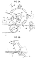
- Fig. 2A is a partial enlarged view showing the second transfer section according to the first embodiment
- Fig. 2B is an explanatory view showing the relation between the width of the second transfer nip and the width of the concaved portion.
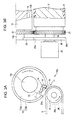
- Fig. 3A is an explanatory view similar to Fig. 2A and shows the state in which the concaved portion is positioned on the second transfer nip position according to the first embodiment
- Fig. 3B is an explanatory drawing viewed in a direction indicated by an arrow IIIB of Fig. 3A according to the first embodiment.
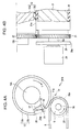
- Fig. 4A is an explanatory view similar to Fig. 2A and shows the state in which concaved portion is not positioned in the second transfer nip according to the first embodiment
- Fig. 4B is an explanatory drawing viewed in a direction indicated by an arrow IVB of Fig. 4A according to the first embodiment.
- Fig. 5 is a block diagram showing a control for an intermediate transfer belt and a second transfer roller driving motor of the first embodiment.
- Fig. 6 is an explanatory view showing the sequence control for the intermediate transfer belt and the second transfer roller driving motor of a first embodiment.
- Fig. 7 is a flow chart showing the image forming operation until rotations of the intermediate transfer belt and the second transfer roller driving motor are stopped according to the first embodiment.
- Fig. 8A is a partial view similar to Fig. 3A and shows the image forming apparatus according to a second embodiment of the present invention.
- Fig. 8B is an explanatory drawing viewed in a direction indicated by an arrow VIIIB of Fig. 8A .
- Fig. 9A is a view similar to Fig. 4A and shows the state in which the concaved portion is not positioned in the second transfer nip according to the second embodiment of the invention.
- Fig. 9B is an explanatory drawing viewed in a direction indicated by an arrow IXB of Fig. 9A .
- Fig. 10 is a block diagram showing the control for a second transfer roller driving motor and intermediate transfer belt driving motor of the second embodiment.
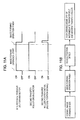
- Fig. 11A is an explanatory view showing the sequence control for an intermediate transfer belt driving motor and a second transfer roller driving motor according to the second embodiment.
- Fig. 11B is a flow chart showing the image forming operation until rotations of the intermediate transfer belt driving motor and the second transfer roller driving motor are stopped according to the second embodiment.
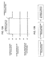
- Fig. 12A is an explanatory view showing the signal in the sequence control for an intermediate transfer belt driving motor and a second transfer roller driving motor according to a third embodiment.
- Fig. 12B is a flow chart showing a process of controlling the intermediate transfer belt until the intermediate transfer belt driving motor is turned off according to the third embodiment.
- Fig. 13A is a partial view similar to Fig. 2A and shows the second transfer section of the image forming apparatus according to a fourth embodiment of the present invention.
- Fig. 13B is an explanatory view showing a detection of presence or absence of the transfer material according to the fourth embodiment.
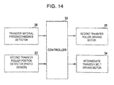
- Fig. 14 is a block diagram similar to Fig. 10 and shows the control for each of the second transfer roller driving motor and the intermediate transfer belt driving motor according to the fourth embodiment.
- Fig. 15A is a flow chart showing a process of controlling the second transfer roller driving motor until the driving motor is turned off when a jam of the transfer material occurs.
- Fig. 15B is an explanatory view showing a signal in the sequence control for an intermediate transfer belt driving motor and a second transfer roller driving motor when a jam of the transfer material occurs.
- Fig. 16 is a partial view showing the image forming apparatus according to a fifth embodiment of the invention.
- Fig. 17 is a block diagram similar to Fig. 14 and shows a control for each of the second transfer roller driving motor and the intermediate transfer belt driving motor of a fifth embodiment.
- Fig. 18A is a flow chart showing a process of controlling the second transfer roller driving motor until the driving motor is turned off when a second jam of the transfer material occurs.
- Fig. 18B is an explanatory view showing a signal in the sequence control for each of the intermediate transfer belt driving motor and the second transfer roller driving motor when a second jam of the transfer material occurs.
- Fig. 1 is a schematic and partial diagram showing the image forming apparatus according to the first embodiment of the invention.
- the image forming apparatus 1 of the first embodiment forms an image using a liquid developer including toner particles and transfer liquid.
- the image forming apparatus 1 includes photosensitive bodies 2Y, 2M, 2C and 2K which is the image carrier including yellow Y, magenta M, cyan C and black K arranged horizontally, or in tandem nearly horizontally.
- 2Y is a yellow photosensitive body
- 2M is a magenta photosensitive body
- 2C is a cyan photosensitive body
- 2K is a black photosensitive body in each of the photosensitive bodies 2Y, 2M, 2C and 2K.
- each of the colors of the other members attaches the colors of Y, M, C and K at the end of numbers respectively as described above.
- Each of the charging sections 3Y, 3M, 3C and 3K is installed around the photosensitive bodies 2Y, 2M, 2C and 2K, respectively.
- Exposure sections 4Y, 4M, 4C and 4K which are the image writing sections, developing sections 5Y, 5M, 5C and 5K, first transfer sections 6Y, 6M, 6C and 6K, and the photosensitive bodies cleaning sections 7Y, 7M, 7C and 7K are installed in this order in the rotational direction ⁇ of the photosensitive bodies 2Y, 2M, 2C and 2K from each of the charging sections 3Y, 3M, 3C and 3K.
- the image forming apparatus 1 includes a transfer belt, more specifically, an endless shaped intermediate transfer belt 8.
- the intermediate transfer belt 8 preferably constitutes an image carrier of the first embodiment.
- the intermediate transfer belt 8 is positioned above each of the photosensitive bodies 2Y, 2M, 2C and 2K.
- the intermediate transfer belt 8 is press contacted to each of the photosensitive bodies 2Y, 2M, 2C and 2K with a first transfer section 6Y, 6M, 6C and 6K, respectively.
- the intermediate transfer belt 8 is preferably formed by 3 layered structure which is made by a relatively soft elastic belt, including a flexible substrate for example resin, an elastic layer, for example, rubber layer, formed on the surface of the substrate, and an outer layer formed on the surface of the elastic layer.
- a relatively soft elastic belt including a flexible substrate for example resin, an elastic layer, for example, rubber layer, formed on the surface of the substrate, and an outer layer formed on the surface of the elastic layer.
- the intermediate transfer belt disclosed to in JP-A-2009-36943 can be employed.
- the description of the intermediate transfer belt described in JP-A-2009-36943 is omitted because the intermediate transfer belt can be understood from the description therein.
- the intermediate transfer belt 8 is not limited to the belt described in JP-A-2009-36943 .
- the intermediate transfer belt 8 is located tightly between the intermediate transfer belt driving roller 9 and the intermediate transfer belt tension roller 10.
- the intermediate transfer belt driving roller 9 is driven by the intermediate transfer belt driving motor (not shown).
- the intermediate transfer belt 8 is rotated in a rotational moving direction ⁇ , in a tensioned state.
- the location order of the photosensitive bodies corresponding to each of the colors Y, M, C and K is not limited to Fig. 1 and may be arranged arbitrarily.
- a second transfer section 11 which is a transfer apparatus, is installed on the intermediate transfer belt driving roller 9 side of the intermediate transfer belt 8.
- the second transfer section 11 includes a second transfer roller 12 and a second transfer cleaning section 13.
- the second transfer roller 12 includes a substrate having a concaved portion 14 which is formed on the circumferential surface of the substrate 12a and extending to the axial direction of second transfer roller 12.
- the second transfer roller 12 further includes, an elastic member 12b which is formed with a sheet type elastic layer, for example, rubber which is wound on the circumferential surface of a circular section of the substrate 12a, except for the concaved portion 14.
- both ends of the elastic member 12b are fixed on the side walls of the concaved portion 14 though it is not shown in the drawings.
- the length of the elastic member 12b which is located on the circular shaped outer circumferential surface of the second transfer roller 12 in the direction of the periphery is set longer than the size of the moving direction of transfer material 19, in which the moving direction size of the transfer material 19 used in the image forming apparatus 1 is the maximum size.
- a resist layer is formed with the elastic member 12b on the circumferential surface of the circular section of the second transfer roller 12.
- an elastic material which is used in an elastic layer known in the related art such as the intermediate transfer belt of the image forming apparatus, can be used (for example, the elastic layer such as urethane of the intermediate transfer belt 8 as described in JP-A-2009- 39643 ).
- the elastic member 12b of the second transfer roller 12 is press contacted to the intermediate transfer belt 8 by bias force of a bias member like spring, not shown in the drawings. Accordingly, the second transfer nip 11a is formed between the intermediate transfer belt 8 and the elastic member 12b of the second transfer roller 12, as shown in Fig. 1 . At this time, the intermediate transfer belt driving roller 9 functions as a backup roller against the pressure of the second transfer roller 12.
- a straight width w1 of the concaved portion 14 in the circumferential direction of the second transfer roller is set wider than width w2 in the same direction of the second transfer nip 11a (w1>w2).
- a measurement method of the nip width w2 will be described. First of all, two liquid curable silicon rubbers for the template are coated on the portion where the nip is formed for the measurement of the second transfer roller 12.
- the two liquid curable silicon rubbers of the second transfer roller 12 are pressed to the belt driving roller 9 of the second transfer roller 12 with a constant pressure, which forms a concaved portion with the two liquid curable silicon rubbers.
- EXAFINE injection type; available from GC Corporation
- the width of the nip forming section which is the thin film portion of the concaved portion is measured using the vernier calipers. The width of the measured nip forming section is the nip width w2.
- the transfer bias is applied to the second transfer roller 12.
- the second transfer roller 12 is rotated in the rotational direction ⁇ , and at the same time the transfer bias is applied when the second transfer roller 12 is moved to the moving direction ⁇ of the intermediate transfer belt 8, so that the toner image which is transferred to the intermediate transfer belt 8 with the transfer nip 11a is transferred to the transfer material like paper.
- the gripper 15 which is a gripping member to pinch the transfer material
- the gripper support member 16 which is an access receiving member receiving the gripper and seated by the gripper 15, and a separating click 17 which is a member for separating the transfer material, are installed in the concaved portion 14.
- the gripper 15 is installed in a predetermined number along the axial direction of second transfer roller 12, and each gripper 15 is formed in a shape of the teeth of a comb.
- the gripper support member 16 is installed on the corresponding position of each gripper 15 and the separating click 17 is installed between the comb teeth, and at the outside of the comb teeth, which is located at both ends of the gripper 15.
- the image forming apparatus 1 has a gate roller 18 corresponding transfer section of the transfer material which transports the transfer material toward the second transfer nip 11a. Also, the gate roller 18 supplies the transfer material 19 to the second transfer nip 11a when the toner image which is transported by the second transfer belt 8 is secondarily transferred.
- the gripper 15 is rotated toward the gripper support member 16 just before the concaved portion 14 reaches to the second transfer nip 11a, so that the gripper 15 pinches the leading edge 19a of the transfer material 19 which is transported toward the direction of the transportation direction gripper support member 16 from the gate roller 18 with the gripper support member 16.
- the toner image which is carried on the intermediate transfer belt 8 is transferred onto the transfer material 19 at the second transfer nip 11a.
- each separating click 17 is projected to its projection position. Accordingly, the back surface of the leading edge of the transfer material 19 (the opposite surface of the toner image transfer surface of the transfer material) is projected from each separating click 17. In this way, the transfer material 19 is separated from the transfer roller 12. Then, each separating click 17 returns within the concaved portion 14.
- Each operation of the gripper 15 and the separating click 17 is controlled by the gripper control cam and separating click control cam which are not shown in the drawings, by the rotation of the second transfer roller 12.
- the intermediate transfer belt driving roller 9 and the second transfer roller 12 are rotated by one common intermediate transfer belt and the second transfer roller driving motor 20.
- the driving force of the intermediate transfer belt and the second transfer roller driving motor 20 is delivered to the intermediate transfer belt driving roller 9, so that the intermediate transfer belt driving roller 9 is rotated counterclockwise, indicated as an arrow in Fig. 3A .
- the driving force of the intermediate transfer belt and the second transfer roller driving motor 20 is delivered to the second transfer roller 12 through the intermediate gear 21 which is integrally installed to be rotatable on the shaft 9a of the intermediate transfer belt driving roller 9 and the second transfer roller driving gear 22 is integrally installed to be rotatable on shaft 12c of the second transfer roller 12. Accordingly, the second transfer roller 12 is rotated clockwise, indicated as direction ⁇ in Fig. 3A .
- a photo sensor 23 is the second transfer roller position detector (corresponding to the transfer roller position detector) for detecting the rotational position of the second transfer roller 12 and cam for photo sensor 24 is located near photo sensor 23 are installed at the end of the second transfer roller 12.
- the cam 24 for the photo sensor 23 has a circular plate having a notch 24a, and is integrally installed to the second transfer roller 12 so as to be rotatable to shaft 12c of the second transfer roller 12.
- the photo sensor 23 detects the rotational position of the notch 24a of the cam 24 for the photo sensor 23, so that it detects the position of the second transfer roller 12 to output the second transfer roller position signal (ON signal) having a pulse shape.
- the concaved portion 14 is integrally installed to be rotatable with the second transfer roller 12, so that relative position between the rotational position of the second transfer roller 12 and the rotational position of the concaved portion 14 is not changed, and both rotational positions are determined at once.
- the second transfer roller position signal which is output by the photo sensor 23 is the signal of the position of the concaved portion 14, and the photo sensor 23 and the cam 24 for the photo sensor is the position detector of the concaved portion which detects the rotational position of concaved portion 14.
- the photo sensor 23 outputs one of the second transfer roller position signals (ON signal)
- the second transfer roller position signal maintains an OFF signal until it newly detects the next concaved portion 14 position.
- the center of notch detector 23a of the photo sensor 23 is arranged on the imaginary straight line ⁇ which connects the center of the rotational shaft 9a of the intermediate transfer belt driving roller 9 to the center of the rotational shaft 12c of the second transfer roller 12, so that it is attached on the apparatus body, for example.
- the circumferential center of the second transfer roller of notch 24a is arranged on the imaginary straight line ⁇ which connects the circumferential center of the second transfer roller concaved portion 14 to the center of rotational shaft 12c. Accordingly, the concaved portion 14 is positioned on the second transfer nip 11a when the notch detector 23a of the photo sensor 23 detects the notch 24a and outputs the second transfer roller position signal (ON signal).
- the partial circular shape outer surface 25a of the contact member 25 having a fan-shape substantially on the side of the second transfer roller 12 is integrally installed to be rotatable with the second transfer roller 12 at the rotational shaft 12c of the second transfer roller 12.
- a circular shape contact member 26 on the side of the intermediate transfer belt 8 is installed to be unmovable to the axial direction of the rotational shaft 9a and relatively rotatable with the rotational shaft 9a at the rotational shaft 9a of the intermediate transfer belt driving roller 9.
- the concaved portion 14 When the concaved portion 14 is positioned on the second transfer nip 11a, the partial circular shape outer surface 25a of the contact member 25 on the side of the second transfer roller 12 is contacted with the outer surface 26a of the contact member 26 on the side of the intermediate transfer belt 8 and both rotational shafts 9a, 12c are positioned to so as not approach each other or so as to substantially not approach each other. Accordingly, when the concaved portion 14 is positioned on the second transfer nip indicated by an imaginary dotted line, the second transfer roller 12 (more specifically, the elastic member 12b) is not contacted with the intermediate transfer belt 8 via access suitable means not shown in the drawings.
- concaved portion 14 with width w1 is set larger than the second transfer nip 11a with a width of w2, concaved portion 14 of the location of second transfer nip transfer roller 12 can be relied upon not to contact intermediate transfer belt 8.
- the second transfer roller cleaning section 13 removes the liquid developer which is attached on the elastic member 12b of the second transfer roller 12 with a cleaning member, such as a cleaning blade.
- the liquid developer which is removed by the cleaning member is returned to the liquid developer carrier.
- the image forming apparatus 1 has a first air flow generator 27, a second air flow generator 28, a transfer material transporter 29, a third air flow generator 30 and an image fixing section 31.
- the first air flow generator 27 blows air toward the leading edge 19a of the transfer material 19 which is released from the pinch of the gripper 15 as indicated by the arrow. Accordingly, it is prevented that the leading edge 19a of the transfer material 19 is moved with the intermediate transfer belt 8 simultaneously.
- the second air flow generator 28 absorbs the air as indicated by the arrow.
- the back surface of the transfer material 19 is separated from the second transfer roller 12 which is absorbed by the air suction of the second air flow generator 28. Accordingly, the transfer material 19 is absorbed to the second air flow generator 28 while intermediate transfer belt 8 and second transfer roller 12 are transferred to transfer material transporter 29 by heat.
- the transfer material transporter 29 has a plurality of s holes, a transfer material transport belt 29a and suction member 29b rotating in arrow direction in endless shape.
- the transfer material 19 is transported to the transfer material transporter 29, the transfer material 19 is drawn by air suction of suction member 29b, and transported toward the third air flow generator 30 by the transfer material transport belt 29a.
- the third air flow generator 30 suctions air as indicated by the direction of the arrow.
- air suction of the third air flow generator 30 the back surface of the transfer material 19 which is separated from the second transfer roller 12 is absorbed. Accordingly, the transfer material 19 is drawn and guided to the third air flow generator 30, and the transfer material 19 moves toward the image fixing section 31 due to the rotational force of the transfer material transport belt 29a. So, the toner image of the transfer material 19 is heated, pressed and fixed by the image fixing section 31.
- Fig. 5 is a block diagram showing a control for a intermediate transfer belt and a second transfer roller driving motor of a image forming apparatus of first embodiment of the invention.
- the intermediate transfer belt and the second transfer roller driving motor 20 of the first embodiment are controlled by electronic controller (control section) 32 of the image forming apparatus 1.
- controller 32 controls the operation of the intermediate transfer belt and the second transfer roller driving motor 20 on the basis of the second transfer roller position signal (the concaved portion position signal; ON signal) from the photo sensor 23 and the image forming operation finish signal (ON signal) from an image forming operation finish signal output section 33 so as to control the rotation of the intermediate transfer belt 8 and the second transfer roller 12. Therefore, the controller 32 controls the rotational position of the second transfer roller 12 (the rotational position of the concaved portion 14) on the basis of the second transfer roller position signal (ON signal) and the image forming operation finish signal (ON signal).
- Fig. 6 is an explanatory view showing the sequence control for a intermediate transfer belt and a second transfer roller driving motor of a first embodiment.
- Fig. 7 is a flow chart showing the image forming operation until the intermediate transfer belt/second transfer roller driving motor 20 is turned off according to the a first embodiment.
- controller 32 sets the image forming apparatus 1 to normal image forming mode, when the image forming signal 10 is input by a user operating the operation button.
- the normal image forming operation is started by the image forming apparatus 1.
- the intermediate transfer belt and the second transfer roller driving motor 20 are driven (ON).
- the image forming operation finish signal is output from the image forming operation finish signal output section 33 to the controller 32.
- the second transfer roller position signal (ON signal) is output from the photo sensor 23 to controller 32.
- the rotation of the intermediate transfer belt and the second transfer roller driving motor 20 is stopped (OFF).
- the concaved portion 14 of the second transfer roller 12 is located at the second transfer nip 11a position, and the elastic member 12b of the second transfer roller 12 is not in contact with the intermediate transfer belt 8, as shown in Figs. 3A and 3B .
- the sheet shaped elastic member 12b is installed on the circumferential surface of the second transfer roller 12 having the concaved portion 14, and along with this, when the image forming operation is activated, the elastic member 12b is contacted and pressed to the intermediate transfer belt 8 to form the second transfer nip 11a.
- the circumferential direction of concaved portion 14 width w1 of the second transfer roller 12 is set to be larger than the same direction width w2 of the second transfer nip 11a (w1>w2).
- the elastic member 12b is not in contact with the intermediate transfer belt 8, so that the concaved portion 14 stops the second transfer roller 12 and second transfer nip 11a.
- the second transfer nip 11a is not formed between the intermediate transfer belt 8 and the second transfer roller 12. Accordingly, the twist occurrence can be suppressed in the elastic layer of the intermediate transfer belt 8 and the elastic member 12b of the second transfer roller 12, even though the second transfer belt 8 and the second transfer roller 12 is not driven for a long time.
- the twist occurrence can be suppressed in the elastic member 12b of the second transfer roller 12, even though the second transfer belt 8 and the second transfer roller 12 are not driven for a long time. Accordingly, the image defect and/or banding which is caused by the twisting of the elastic member 12b of the second transfer roller 12 can be controlled effectively, whereby a good image quality can be obtained.
- the concaved portion 14 is positioned essentially on the second transfer nip 11a, so that the second transfer roller 12 can always stop in a constant position.
- the rotational position of the second transfer roller 12 can be controlled easily, so that the positioning between the rotational position of the second transfer roller 12 and the transported transfer material 19 can be accomplished easily.
- the transfer material 19 passes the second transfer nip 11a, so that the transfer material 19 can be separated easily from the intermediate transfer belt 8 after the second transfer.
- the intermediate transfer belt 8 has an elastic layer, so that the transfer efficiency can be raised even though the transfer material 19 has high surface roughness.
- the twist occurrence can be suppressed in the elastic layer of the second transfer belt 8 and the elastic member 12b of the second transfer roller 12, because the second transfer nip 11a is not formed even though the second transfer belt 8 and the second transfer roller 12 are not driven for a long time.
- FIGs. 8A, 8B , 9A, 9B , 10 , 11A and 11B an image forming apparatus and method in accordance with a second embodiment will now be explained.
- the parts of the second embodiment that are identical to the parts of the first embodiment will be given the same reference numerals as the parts of the first embodiment.
- the descriptions of the parts of the second embodiment that are identical to the parts of the first embodiment may be omitted for the sake of brevity.
- Fig. 8A is a partial view showing the image forming apparatus of the second embodiment of the invention and is the same partial view as Fig. 3A
- Fig. 8B is an explanatory drawing viewed in the direction indicated by the arrow VIIIB of Fig. 8A
- Fig. 9A is a view showing the second embodiment and is the same partial view as Fig. 4A
- Fig. 9B is an explanatory drawing viewed in the direction indicated by the arrow IXB of Fig. 9A .
- each of the intermediate transfer belt driving roller 9 and the second transfer roller 12 is rotated by the individual intermediate transfer belt driving motor 34 (one example of the image carrier driving source of the present invention) and the second transfer roller driving motor 35 (one example of the transfer roller driving source of the present invention) respectively.
- the driving force of the intermediate transfer belt driving motor 34 is delivered to the intermediate transfer belt driving roller 9, so that the intermediate transfer belt driving roller 9 rotates counterclockwise as indicated by the direction of the arrow when viewed in the direction in Fig. 8A and Fig. 9A .
- the driving force of the second transfer roller driving motor 35 is delivered to the rotational shaft 12c of the second transfer roller 12, so that the second transfer roller 12 rotates clockwise as indicated arrow direction (direction ⁇ ) when viewed in the direction in Fig. 8A and Fig. 9A .
- the intermediate gear 21 and the second transfer roller driving gear 22 in the first embodiment are not provided.
- a contact member of the intermediate transfer belt side includes a bearing 36.
- the bearing 36 is a ball bearing having an inner lace 36a, an outer lace 36b, and ball 36c.
- the inner lace 36a is integrally attached to be rotatable with the rotational shaft 9a of the intermediate transfer belt driving roller 9. Accordingly, the outer lace 36b can rotate relatively with respect to the rotational shaft 9a.
- the partial circular shape outer circumferential surface 25a of the contact member 25 contacts the outer circumferential surface 36b1 of the outer lace 36b when the concaved portion 14 of the second transfer roller 12 is located on the second transfer nip 11a position. Accordingly, the elastic member 12b of the second transfer roller 12 is separated from the intermediate belt 8 when the concaved portion 14 is located on the second transfer nip 11a position. Further, as shown in Figs.
- the partial circular shape outer circumferential surface 25a of the contact member 25 is separated from the outer circumferential surface 36b1 of the outer lace 36b when the concaved portion 14 of the second transfer roller 12 is located out of the second transfer nip 11a.
- the elastic member 12b of the second transfer roller 12 is contacted and pressed to the intermediate transfer belt 8, and the second transfer nip 11a is formed.
- the controller 32 controls the rotation of the intermediate transfer belt 8 and the rotation of the second transfer roller 12 by controlling the rotation of the intermediate transfer belt driving motor 34 and the second transfer roller driving motor 35, on the basis of the second transfer roller position signal (the concaved portion position signal; ON signal) from the photo sensor 23 which detects the position of the second transfer roller 12 and the image forming operation finish signal (ON signal) from the image forming operation finish output section 33, in the same manner as the first embodiment. Accordingly, the controller 32 controls the rotational position of the second transfer roller 12 (the rotational position of the concaved portion 14) on the basis of the second transfer roller position signal (ON signal) and the image forming operation finish signal (ON signal).
- the controller 32 controls the rotational position of the second transfer roller 12 (the rotational position of the concaved portion 14) on the basis of the second transfer roller position signal (ON signal) and the image forming operation finish signal (ON signal).
- Fig. 11A is an explanatory view showing the sequence control for the intermediate transfer belt driving motor 34 and a second transfer roller driving motor 35
- Fig. 11B is a flow chart showing the image forming operation until the intermediate transfer belt driving motor 34 and the second transfer roller driving motor 35 are turned off.
- the controller 32 sets the image forming apparatus 1 to the normal image forming mode. In this way, the image forming apparatus 1 starts the normal image forming operation. Accordingly, the intermediate transfer belt driving motor 34 and the second transfer roller driving motor 35 are driven respectively (ON).
- the image forming operation finish signal is output from the image forming operation finish signal output section 33 to the controller 32 in the same manner to the first embodiment.
- the second transfer roller position signal (ON signal) is output from the photo sensor 23 to the controller 32.
- the second transfer roller position signal (ON signal) is input to the controller 32, each rotation of the intermediate transfer belt driving motor 34 and the second transfer roller driving motor 35 is stopped respectively (OFF).
- the concaved portion 14 of the second transfer roller 12 is located on the position of the second transfer nip 11a and the elastic member 12b of the second transfer roller 12 does not contact the intermediate transfer belt 8 as same manner as the first embodiment as shown in Figs. 3A and 3B .
- each rotation of the intermediate transfer belt driving motor 34 and the second transfer roller driving motor 35 can be controlled independently, so that velocity of the intermediate transfer belt driving motor 34 and the second transfer roller driving motor 35 can be set properly, respectively.
- the elastic member 12b of the second transfer roller 12 is not contacted with the intermediate transfer belt 8 when the intermediate transfer belt driving motor 34 is not driven and when the second transfer roller driving motor 35 is not driven. Therefore, in the state that the elastic member 12b is not contacted with the intermediate transfer belt 8, it can control the unstable sliding between the intermediate transfer belt 8 and the elastic member 12b of the second transfer roller 12 when the intermediate transfer belt 8 starts the independent rotation or when the intermediate transfer belt 8 stops the independent rotation after the independent rotation.
- the constitution and effects of the image forming apparatus 1 in the second embodiment are the same as those of the first embodiment.
- FIG. 12A and 12B an image forming apparatus and method in accordance with a third embodiment will now be explained.
- the parts of the third embodiment that are identical to the parts of the second embodiment will be given the same reference numerals as the parts of the second embodiment.
- the descriptions of the parts of the third embodiment that are identical to the parts of the second embodiment may be omitted for the sake of brevity.
- Fig. 12A is an explanatory view showing a signal in the sequence control for a intermediate transfer belt driving motor 34 and the second transfer roller driving motor 35 of the image forming apparatus of the third embodiment
- Fig. 12B is a flow chart showing a management of the intermediate transfer belt 8 until the intermediate transfer belt driving motor 34 is turned off.
- the intermediate transfer belt 8 is driven, so that the intermediate transfer belt 8 undergoes a process such as cleaning or resist matching with respect to the intermediate transfer belt 8.
- the intermediate transfer belt driving motor 34 and the second transfer roller driving motor 35 can use the block diagram of Fig. 10 in the same manner as the second embodiment.
- the controller 32 controls the actuation of the intermediate transfer belt driving motor 34, in the other words, the rotation of the intermediate transfer belt 8 on the basis of the second transfer roller position signal (the concaved portion position signal; ON signal) from the photo sensor 23 and the intermediate transfer belt processing signal (ON signal) from the intermediate transfer belt processing signal output section 37. Accordingly, the controller 32 controls the rotational position of the second transfer roller 12 (the rotational position of the concaved portion 14) on the basis of the position signal (ON signal) of the second transfer roller and the finish signal (ON signal) of the image forming operation.
- the controller 32 sets the image forming apparatus 1 to the intermediate transfer belt processing mode, when the intermediate transfer belt processing signal is input to the controller 32 from the intermediate transfer belt processing signal output section.
- the intermediate transfer belt processing mode refers to a mode in which the intermediate transfer belt 8 undergoes the cleaning or resist matching.
- the image forming apparatus 1 is set to the intermediate transfer belt processing mode, so that the controller 32 actuates the intermediate transfer belt driving motor 34 (ON) and the intermediate transfer belt 8 rotates in the direction ⁇ (shown in Fig. 8A ). At this time, the second transfer roller 12 is stopped, so the concaved portion 14 is located on the second transfer nip 11a position.
- the elastic member 12b of the second transfer roller 12 is not contacted with the intermediate transfer belt 8 and the intermediate transfer belt 8 rotates stably and smoothly.
- the intermediate transfer belt 8 is processed by the rotation of the intermediate transfer belt 8 as described above.
- the intermediate transfer belt processing finish signal is output from the intermediate transfer belt processing signal output section to controller 32, when the processing regarding the intermediate transfer belt 8 is finished.
- the controller 32 stops the actuation of the intermediate transfer belt driving motor 34, and the rotation of the intermediate transfer belt 8 is stopped.
- the intermediate transfer belt 8 is rotated.
- the elastic member 12b of the second transfer roller 12 is not contacted with the intermediate transfer belt 8
- the second transfer roller 12 in which the second transfer roller 12 always contacts presses the intermediate transfer belt, when the cleaning or resist matching of the intermediate transfer belt 8 is processed, the distance between the rotational shaft of the second transfer roller and the rotational shaft of the intermediate transfer belt driving roller 9 is changed, so that it is necessary to separate the second transfer roller 12 from the intermediate transfer belt 8.
- the second transfer roller 12 can be separated from the intermediate transfer belt 8 without substantially changing the distance between the rotational shaft 12c of the second transfer roller 12 and the rotational shaft 9a of the intermediate transfer belt driving roller 9.
- the processing with respect to the intermediate transfer belt 8 described above can be processed easily.
- the constitution and effects of the image forming apparatus 1 in the third embodiment are the same as those of the second embodiment.
- FIG. 13A, 13B , 14 , 15A and 15B an image forming apparatus and method in accordance with a fourth embodiment will now be explained.
- the parts of the fourth embodiment that are identical to the parts of the previous embodiments will be given the same reference numerals as the parts of the previous embodiment.
- the descriptions of the parts of the fourth embodiment that are identical to the parts of the previous embodiments may be omitted for the sake of brevity.
- Fig. 13A is a partial view similar to Fig. 2A showing a second transfer section of the fourth embodiment of the image forming apparatus of the invention
- Fig. 13B is an explanatory drawing a detection of the transfer material presence
- Fig. 14 is a block diagram similar to Fig. 10 showing the control for each of the second transfer roller driving motor 34 and the intermediate transfer belt driving motor 35 of the fourth embodiment.
- the image forming apparatus of the fourth embodiment has the transfer material presence /absence detector 38 using a reflective type sensor between the second transfer nip 11a and the gate roller 18.
- the transfer material presence/absence detector 38 outputs OFF signal when the transfer material 19 which is transported from the gate roller 18 is detected at the transfer material detection timing position detecting the transfer material 19, and outputs ON signal when the transfer material 19 is not detected at the same position.
- the transfer material presence/absence detector 38 outputs ON signal, when the transfer material 19 is not detected at the detection timing position.
- ON signal output from the transfer material presence/absence detector 38 is the transfer material presence/absence signal (ON signal).
- a photo interrupter from Sharp Corporation GPS2A25J0000F series
- the photo sensor 23 detecting the position of the second transfer roller 12, the transfer material presence/absence detector 38, the transfer material belt driving motor 34 and the second transfer roller driving motor 35 are connected to the controller 32.
- the controller 32 controls the actuation of the second transfer roller driving motor 35, and controls the rotational position (the rotational position of the concaved portion 14) of the second transfer roller 12, on the basis of the second transfer roller position signal (the concaved portion position signal; ON signal) from the photo sensor 23 and the transfer material presence/absence signal (ON signal) from the transfer material presence/absence detector 38.
- the transfer material presence/absence signal (ON signal) is input to the controller 32 from the transfer material presence/absence detector 38, and it is determined that the transfer material 19 is jammed, then the second transfer roller position signal (ON signal) is input to stop the actuation of the second transfer roller driving motor 35.
- Fig. 15A is a flow chart showing a process of the second transfer roller driving motor 35 until the second transfer driving motor 35 is turned off when a jam of the transfer material 19 occurs
- Fig. 15B is an explanatory view showing a signal in the sequence control for the intermediate transfer belt driving motor 34 and the second transfer roller driving motor 35 when a jam of the transfer material 19 occurs.
- the controller 32 sets the image forming apparatus to the image forming mode. Accordingly the image forming apparatus 1 starts the normal image forming operation.
- each of the intermediate transfer belt driving motor 34 and the second transfer roller driving motor 35 is driven respectively (ON), and the intermediate transfer belt 8 rotates in the direction ⁇ shown in Fig. 1 , and the second transfer roller 12 rotates in the direction ⁇ shown in Fig. 13A .
- the transfer material 19 enters the second transfer nip 11a.
- the toner image which is transferred by the intermediate transfer belt 8 is transferred to the transfer material 19.
- the transfer material presence/absence detector 38 does not detect the transfer material 19, and outputs the transfer material presence/absence signal (ON signal; signal that the transfer material is absent) until the transfer material 19 which is transported from the gate roller 18 reaches the detection timing position of the transfer material presence/absence detector 38.
- the transfer material presence/absence detector 38 outputs the transfer material presence/absence signal (OFF signal; signal that the transfer material is present). In other words, the jam of the transfer material 19 does not occur (when the jam does not occur).
- the transfer material presence/absence detector 38 when the transfer material presence/absence detector 38 does not detect the transfer material 19 at the detection timing position, regardless of whether the jam of the transfer material occurs or does not occur, the transfer material presence/absence detector 38 outputs ON signal, so that any of ON signals is indicated as the transfer material presence/absence signal (ON signal) for convenience of the description in Fig. 15B .
- the transfer material presence/absence detector 38 outputs the transfer material presence/absence signal (ON signal) again, until the next second transfer roller position signal (ON signal) is output.
- the transfer material presence/absence detector 38 does not detect the transfer material 19 at the detection timing position. Because of this, the transfer material presence/absence signal from the transfer material presence/absence detector 38 does not become OFF, and the transfer material presence/absence detector 38 outputs the transfer material presence/absence signal (ON signal) to the controller 32 continuously (detection that the transfer material is absent). In other words, the jam of the transfer material 19 occurs (when the jam occurs).
- the controller 32 determines that the jam of the transfer material 19 has occurred, and when the second transfer roller position signal (ON signal) is input subsequently, the actuation of the second transfer roller driving motor 35 is stopped. Accordingly, when the jam of the transfer material 19 occurs, the second transfer roller 12 is stopped in the state that the elastic member 12b is not contacted to the intermediate transfer belt 8. Then, the controller 32 stop the actuation of the intermediate transfer belt driving motor 34, and the intermediate transfer belt 8 is stopped.
- the second transfer roller 12 rotates until the concaved portion 14 reaches the position of the second transfer nip 11a, and when the concaved portion 14 reaches the position of the second transfer nip 11a, the second transfer roller 12 is stopped.
- the intermediate transfer belt 8 rotates too.
- the intermediate transfer belt 8 does not necessarily have to rotate. However, it is preferable to rotate the intermediate transfer belt 8 when the second transfer roller 12 rotates after the jam of the transfer material 19 is detected to decrease the friction between the second transfer roller 12 and the intermediate transfer belt 8.
- the controller 32 stops the rotation of the second transfer roller 12 so that the concaved portion 14 is located to the position of the second transfer nip 11a on the basis of the second transfer roller position signal (ON signal) and the transfer material presence/absence signal (ON signal) from the transfer material presence/absence detector 38.
- the toner of the image transported on the intermediate transfer belt 8 may be attached on the second transfer roller 12.
- the detection timing position of the transfer material presence/absence detector 38 for detecting the transfer material 19 is set immediately upstream of the detection position of the concaved portion 14 by the photo sensor 23, so that it can be more effectively suppressed that the toner of the image carried on the meddle transfer belt 8 may be attached on the second transfer roller 12.
- the constitution and effects of the image forming apparatus 1 in the fourth embodiment are the same as those in the second embodiment.
- FIG. 16 , 17 , 18A and 18B an image forming apparatus and method in accordance with a fifth embodiment will now be explained.
- the parts of the fifth embodiment that are identical to the parts of the previous embodiments will be given the same reference numerals as the parts of the previous embodiments.
- the descriptions of the parts of the fifth embodiment that are identical to the parts of the previous embodiments may be omitted for the sake of brevity.
- Fig. 16 is a partial view showing the image forming apparatus according to the fifth embodiment of the invention.
- Fig. 17 is a block diagram similar to Fig. 14 showing a control for each of the second transfer roller driving motor 34 and the intermediate transfer belt driving motor 35 of the fifth embodiment.
- the second air flow generator 28 has the second transfer material presence /absence detector 39.
- the second transfer material presence/absence detector 39 detects the jam of the transfer material 19 which is already detected by the first transfer material presence/absence detector 38.
- the second transfer material presence/absence detector 39 may be the same as the first transfer material presence/absence detector 38, for example, a photo sensor may be used as described above.
- the photo sensor 23 which detects the position of the second transfer roller 12, the first transfer material presence/absence detector 38, the second transfer material presence/absence detector 39, the intermediate transfer belt driving motor 34 and the second transfer roller driving motor 35 are connected to the controller 32.
- the controller 32 controls the actuation of the second transfer roller driving motor 35, and controls the rotational position (rotational position of the concaved portion 14) of the second transfer roller 12 (rotational position of the concaved portion 14), on the basis of the second transfer roller position signal (the concaved portion position signal; ON signal) from the photo sensor 23, the first transfer material presence/absence signal (ON signal) from the first transfer material presence/absence detector 38 and the second transfer material presence/absence signal (ON signal) from the second transfer material presence/absence detector 39.
- the first transfer material presence/absence signal (ON signal) from the first transfer material presence/absence detector 38 is input in the controller 32 in the state that the second transfer roller 12 rotates in the direction ⁇ (forward rotational direction).
- the actuation of the second transfer roller driving motor 35 is stopped when the second transfer roller position signal (ON signal) is input initially in the same manner as described above in the fourth embodiment.
- the concaved portion 14 of the second transfer roller 12 is stopped on the position of the second transfer nip 11a when the jam of the transfer material 19 has occurred ahead of the first transfer material presence/absence detector 38 in the moving direction of the transfer material. Accordingly, if the second transfer roller 12 is stopped, when a jam of the transfer material 19 occurs, the elastic member 12b of the second transfer roller 12 is not contacted to the intermediate transfer belt 8.
- the controller 32 determines there is no jam occurrence of the transfer material 19 because the first transfer material presence/absence signal (OFF signal) is input from the first transfer material presence/absence detector 38, and the controller 32 determines there is a jam occurrence of the transfer material 19 because the second transfer material presence/absence signal (ON signal) is input from the second transfer material presence/absence detector 39, the concaved portion 14 passes through the second transfer nip 11a, so that the second transfer roller driving motor 35 rotates in reverse.
- the second transfer roller 12 is controlled to rotate in reverse (reverse to the direction ⁇ ). After that, when the second transfer rotational position signal (ON signal) is input, the actuation of the second transfer roller driving motor 35 is stopped.
- the second transfer roller 12 rotates in reverse so that the concaved portion 14 is stopped at the position of the second transfer nip 11a.
- the elastic member 12b of the second transfer roller 12 is not contacted to the intermediate transfer belt 8 when the second transfer roller 12 is stopped.
- Fig. 18A is a flow chart showing a process of the second transfer roller driving motor 35 until the driving motor 35 is turned off when a second jam of the transfer material occurs
- Fig. 18B is an explanatory view showing a signal in the sequence control for each of the intermediate transfer belt driving motor 34 and the second transfer roller driving motor 35 when a second jam of the transfer material occurs.
- the controller 32 sets the image forming apparatus 1 to the image forming mode.
- the image forming apparatus 1 starts normal image forming operation.
- the intermediate transfer belt driving motor 34 and the second transfer roller driving motor 35 are driven respectively (ON), so that the intermediate transfer belt driving motor 34 rotates in the direction ⁇ (forward direction), and the second transfer roller driving motor 35 rotates in the direction ⁇ (forward direction).
- the transfer material 19 enters the second transfer nip 11a.
- the toner image transported on the intermediate transfer belt 8 is transferred to the transfer material 19 at the second transfer nip 11a.
- the first transfer material presence/absence detector 38 does not detect the transfer material 19, and outputs the first transfer material presence/absence signal (ON signal) until the transfer material 19 which is transported from the gate roller 18 reaches the detection timing position of the first transfer material presence/absence detector 38. If the first transfer material presence/absence detector 38 detects the transfer material 19 as the transfer material 19 reaches the detection timing position of the first transfer material presence/absence detector 38, the first transfer material presence/absence signal from the first transfer material presence/absence detector 38 becomes OFF. In other words, the transfer material 19 does not jam (when the jam does not occur).
- the second transfer material presence/absence detector 39 does not detect the transfer material 19 and outputs the second transfer material presence/absence signal (ON signal), until the transfer material 19 reaches the detection timing position of the second transfer material presence/absence detector 39.
- the second transfer material presence/absence detector 39 detects the transfer material 19
- the second transfer material presence/absence signal from the second transfer presence/absence detector 39 becomes OFF. That is to say, the jam of the transfer material 19 does not occur (when the jam does not occur).
- the first transfer material presence/absence detector 38 does not detect the transfer material 19 at the detection timing.
- the rotation of the second transfer roller 12 is stopped in the state that the elastic member 12b does not contact the intermediate transfer belt 8 in the same manner as the fourth embodiment described above.
- the second transfer material presence/absence detector 39 does not detect the transfer material 19 at the detection timing position. Therefore, the second transfer material presence/absence signal from the second transfer material presence/absence detector 39 does not become OFF, and the second transfer material presence/absence detector 39 outputs the second transfer material presence/absence signal (ON signal) to the controller 32 continuously (the second transfer material jam occurs). In other words, the jam of the transfer material 19 occurs (when the jam occurs).
- the controller 32 determines that the second transfer material jam of the transfer material is occurring, and the second transfer roller driving motor 35 rotates in reverse. Namely, if the jam is detected after the second transfer roller 12 rotates forward; the roller 12 is stopped instantly and is then rotated in reverse. Also, at this time, the controller 32 rotates the intermediate transfer belt driving motor 34 in reverse, so that the intermediate transfer belt 8 is also rotated in reverse. After that, each actuation of the second transfer roller driving motor 35 and the intermediate transfer belt driving motor 34 is stopped respectively when the second transfer roller position signal (ON signal) is input initially. Accordingly, the second transfer roller 12 is stopped in the state in which the elastic member 12b is not contacted to the intermediate transfer belt 8, when the second transfer material jam of the transfer material 19 occurs.
- the second transfer roller 12 rotates in reverse until the concaved portion 14 reaches the position of the second transfer nip 11a, and it is stopped when the concaved portion 14 reaches the position of the second transfer nip 11a.
- the intermediate transfer belt 8 also rotates in reverse.
- the intermediate transfer belt 8 does not necessarily need to rotate in reverse when the second transfer roller 12 rotates in reverse after the second jam of the transfer material 19 occurs.
- the controller 32 controls the second transfer roller 12 so as to rotate in reverse, on the basis of the second transfer roller position signal (ON signal) and the second transfer material presence/absence signal (ON signal) from the second transfer material presence/absence detector 39. Then, the reverse rotation of the second transfer roller 12 is stopped when the concaved portion 14 is located at the second transfer nip 11a position. Thus, it can suppress the toner which is transported by the intermediate transfer belt 8 that may attach the second transfer roller 12.
- the constitution and effects of the image forming apparatus in the fifth embodiment are the same as those of the fourth embodiment.
- the second transfer material presence/absence detector 39 can be located at any one of the inner side of the endless shaped transfer material transport belt 29a of the transfer material transporter 29, the third air flow generator 30, the front side of the image fixing section 31, and the rear side of the image fixing section 31.
- the image forming apparatus and the image forming method of the invention are not limited to the above described preferred embodiments.
- the intermediate transfer belt 8 is used as the image carrier, however, the intermediate transfer drum or photo sensor can be used as the image carrier.
- the toner image of the photosensitive body is directly transferred to the transfer material.
- the image forming apparatus has 4 colors; however the image forming apparatus may have a single color.
Landscapes
- Physics & Mathematics (AREA)
- General Physics & Mathematics (AREA)
- Electrostatic Charge, Transfer And Separation In Electrography (AREA)
- Control Or Security For Electrophotography (AREA)
Abstract
An image forming apparatus (1) includes: an image carrier (8) that carries an image; a transfer roller (12) that has a elastic member (12b) and a concaved portion (14) at the circumferential surface thereof, the concaved portion (14) having a width in the circumferential direction larger than a width in the circumferential direction of a transfer nip (11a) which is formed by being in contact with the image carrier (8), and transfers the image which is carried by the image carrier (8) onto the transfer material (19) at the transfer nip (11a); a transfer roller position detector (23) that detects the rotational position of the transfer roller (12); and a controller (32) that stops the rotation of the transfer roller (12) when the concaved portion (14) is located at the transfer nip (11a) position, on the basis of the rotational position of the transfer roller (12) detected by the transfer roller position detector (23) when the rotation of the transfer roller (12) is stopped.
Description
- The present invention relates to an electro photographic type image forming apparatus and an image forming method to transfer a toner image onto access transfer material such as paper, and to form an image onto the transfer material using a transfer roller having an elastic member on its circumferential surface.
- In the related art, as an electro photographic type image forming apparatus, the image forming apparatus is suggested in which a transfer material gripping member is installed in a concaved portion of a transfer roller, and a leading edge of the transfer material is pinched by the gripping member and transfers the toner image of the image carrier to the transfer material such as paper (for example, refer to
JP-A-2000-508280 - Additionally, another image forming apparatus is suggested in which a transfer roller having a elastic member on the surface thereof presses onto the image carrier to form a transfer nip, and a toner image of the image carrier is transferred onto the transfer material by applying a transfer bias to the transfer roller (for example,
JP-A- 2009-36943 - In the image forming apparatus described in
JP-A-2009-36943 - An advantage of some aspects of the invention is to provide the image forming apparatus and the image forming method capable of performing a better image transfer and reliably separating the transfer material from the transfer roller.
- According to one aspect of invention, there is provided an image forming apparatus and the image forming method. An elastic member is installed in the circumferential surface of the transfer roller having a concaved portion, along with which a transfer nip is formed where the transfer roller is pressed against to the image carrier when the image is transferred. In this case, the width of the concaved portion is larger than the width of the transfer nip in the circumferential direction of the transfer roller. The transfer roller is stopped when the concaved portion is in the transfer nip, so as not to have contact between the transfer roller and the image carrier when the image is not transferred. Thus, the transfer nip is not formed between the transfer roller and the image carrier when the image forming operation of the image forming apparatus is not performed. Accordingly, the elastic member of the transfer roller is not twisted, even when the image forming apparatus is not operated for a long time. Thus, the image defect and the occurrence of the banding caused by the twisting of the elastic member are suppressed effectively and a higher quality image can be obtained.
- In addition, when the rotation of the transfer roller is stopped, the concaved portion is reliably positioned on the transfer nip position so that the transfer roller can be reliably stopped in a constant position. Accordingly, the rotational position of the transfer roller can be controlled when the next image forming operation is performed, and the positional alignment between the rotational position of the transfer roller and transfer material which is transferred to the apparatus is easily accomplished.
- Additionally, each rotation of the image carrier driver driving the image carrier and the transfer roller driver driving the transfer roller can be controlled independently, so that the rotation velocity of the image carrier driver and the transfer roller driver which drives transfer roller can be controlled properly and individually.
- Also, the elastic member of the transfer roller is not in contact with the image carrier when the image carrier is driven and the transfer roller driver is stopped. In the state in which the elastic member is not in contact with the image carrier, unstable sliding between the elastic member of the transfer roller and the image carrier can be suppressed when the image carrier starts to rotate independently or when the image carrier is stopped after rotating independently.
- Also, in the state in which the rotation of the transfer roller is stopped, the concaved portion rotates the image carrier at the position of the transfer nip. Thus, in the state that the elastic member of the transfer roller is not in contact with the image carrier, the image carrier can be rotated. However, in the case that the transfer roller of the image forming apparatus is always in press contact with the image carrier, it is necessary for the transfer roller to be separated from the image carrier to change the distance between the rotational axis of the transfer roller and the rotational axis of the image carrier, when the image carrier is cleaned or registration alignment thereof is performed. Meanwhile, the present invention has a transfer roller separating from the image carrier without changing the distance between the rotational axis of the transfer roller and the rotational axis of the image carrier substantially. Thus, the operation as described above can be accomplished with easily and briefly.
- In addition, when a jam of the transfer material occurs, the controller stops the rotation of the transfer roller so that the concaved portion is located in the transfer nip position, on the basis of the second transfer roller position signal and the transfer presence/absence signal and in the transfer presence/absence detecting section. Accordingly, it can be suppressed that the toner of the image being carried by the image carrier is attached on the transfer roller. In particular, by setting the location of the transfer material detecting timing position of the transfer material presence/absence detecting section to just before the concaved portion detecting position on the front of the transfer roller position, the toner of the image being carried by the image carrier can be more effectively suppressed from being attached on the transfer roller.
- Also, when a jam of the transfer material passing through the transfer nip at the transfer presence/absence detecting section is detected, the controller stops the reverse rotation of the transfer roller when the concaved portion is located on the transfer nip position after reverse rotation of the transfer roller, on the basis of the transfer roller position signals and the transfer material presence/absence signals of the transfer presence/absence detecting section. Accordingly, it can be more effectively suppressed that the toner of the image being carried by the image carrier is attached on the transfer roller.
- Also, in the state in which the transfer material is pinched by the transfer material gripper, the transfer material passes through the transfer nip, so that separation of the transfer material from the image carrier can be reliably accomplish after the image is transferred.
- Also, the image carrier has an elastic layer, so that the transfer efficiency can be enhanced even though the transfer material has high surface roughness. Even if this image carrier has the elastic layer, the transfer nip is not formed in the case that the image carrier and the transfer roller is stopped for a long time, so that it is possible to suppress the occurrence of twisting occurrence between the elastic layer of the image carrier and the elastic layer of the transfer roller.
- The invention will be described with reference to the accompanying drawings, wherein like numbers reference like elements.
-
Fig. 1 is a schematic partial diagram showing the image forming apparatus according to the first embodiment of the invention. -
Fig. 2A is a partial enlarged view showing the second transfer section according to the first embodiment, andFig. 2B is an explanatory view showing the relation between the width of the second transfer nip and the width of the concaved portion. -
Fig. 3A is an explanatory view similar toFig. 2A and shows the state in which the concaved portion is positioned on the second transfer nip position according to the first embodiment;Fig. 3B is an explanatory drawing viewed in a direction indicated by an arrow IIIB ofFig. 3A according to the first embodiment. -
Fig. 4A is an explanatory view similar toFig. 2A and shows the state in which concaved portion is not positioned in the second transfer nip according to the first embodiment;Fig. 4B is an explanatory drawing viewed in a direction indicated by an arrow IVB ofFig. 4A according to the first embodiment. -
Fig. 5 is a block diagram showing a control for an intermediate transfer belt and a second transfer roller driving motor of the first embodiment. -
Fig. 6 is an explanatory view showing the sequence control for the intermediate transfer belt and the second transfer roller driving motor of a first embodiment. -
Fig. 7 is a flow chart showing the image forming operation until rotations of the intermediate transfer belt and the second transfer roller driving motor are stopped according to the first embodiment. -
Fig. 8A is a partial view similar toFig. 3A and shows the image forming apparatus according to a second embodiment of the present invention.Fig. 8B is an explanatory drawing viewed in a direction indicated by an arrow VIIIB ofFig. 8A . -
Fig. 9A is a view similar toFig. 4A and shows the state in which the concaved portion is not positioned in the second transfer nip according to the second embodiment of the invention.Fig. 9B is an explanatory drawing viewed in a direction indicated by an arrow IXB ofFig. 9A . -
Fig. 10 is a block diagram showing the control for a second transfer roller driving motor and intermediate transfer belt driving motor of the second embodiment. -
Fig. 11A is an explanatory view showing the sequence control for an intermediate transfer belt driving motor and a second transfer roller driving motor according to the second embodiment.Fig. 11B is a flow chart showing the image forming operation until rotations of the intermediate transfer belt driving motor and the second transfer roller driving motor are stopped according to the second embodiment. -
Fig. 12A is an explanatory view showing the signal in the sequence control for an intermediate transfer belt driving motor and a second transfer roller driving motor according to a third embodiment.Fig. 12B is a flow chart showing a process of controlling the intermediate transfer belt until the intermediate transfer belt driving motor is turned off according to the third embodiment. -
Fig. 13A is a partial view similar toFig. 2A and shows the second transfer section of the image forming apparatus according to a fourth embodiment of the present invention.Fig. 13B is an explanatory view showing a detection of presence or absence of the transfer material according to the fourth embodiment. -
Fig. 14 is a block diagram similar toFig. 10 and shows the control for each of the second transfer roller driving motor and the intermediate transfer belt driving motor according to the fourth embodiment. -
Fig. 15A is a flow chart showing a process of controlling the second transfer roller driving motor until the driving motor is turned off when a jam of the transfer material occurs.Fig. 15B is an explanatory view showing a signal in the sequence control for an intermediate transfer belt driving motor and a second transfer roller driving motor when a jam of the transfer material occurs. -
Fig. 16 is a partial view showing the image forming apparatus according to a fifth embodiment of the invention. -
Fig. 17 is a block diagram similar toFig. 14 and shows a control for each of the second transfer roller driving motor and the intermediate transfer belt driving motor of a fifth embodiment. -
Fig. 18A is a flow chart showing a process of controlling the second transfer roller driving motor until the driving motor is turned off when a second jam of the transfer material occurs.Fig. 18B is an explanatory view showing a signal in the sequence control for each of the intermediate transfer belt driving motor and the second transfer roller driving motor when a second jam of the transfer material occurs. - The present invention will now be described in terms of the explanatory embodiment with reference to the accompanying drawings.
-
Fig. 1 is a schematic and partial diagram showing the image forming apparatus according to the first embodiment of the invention. - The image forming apparatus 1 of the first embodiment forms an image using a liquid developer including toner particles and transfer liquid. As shown in
Fig. 1 , the image forming apparatus 1 includesphotosensitive bodies photosensitive bodies - Each of the charging
sections photosensitive bodies Exposure sections sections first transfer sections bodies cleaning sections photosensitive bodies sections - Also, the image forming apparatus 1 includes a transfer belt, more specifically, an endless shaped
intermediate transfer belt 8. Theintermediate transfer belt 8 preferably constitutes an image carrier of the first embodiment. Theintermediate transfer belt 8 is positioned above each of thephotosensitive bodies intermediate transfer belt 8 is press contacted to each of thephotosensitive bodies first transfer section - Although it is not shown in the drawings, the
intermediate transfer belt 8 is preferably formed by 3 layered structure which is made by a relatively soft elastic belt, including a flexible substrate for example resin, an elastic layer, for example, rubber layer, formed on the surface of the substrate, and an outer layer formed on the surface of the elastic layer. As an embodiment of theintermediate transfer belt 8, for example, the intermediate transfer belt disclosed to inJP-A-2009-36943 JP-A-2009-36943 intermediate transfer belt 8 is not limited to the belt described inJP-A-2009-36943 intermediate transfer belt 8 is located tightly between the intermediate transferbelt driving roller 9 and the intermediate transferbelt tension roller 10. The intermediate transferbelt driving roller 9 is driven by the intermediate transfer belt driving motor (not shown). Theintermediate transfer belt 8 is rotated in a rotational moving direction β, in a tensioned state. - Also, the location order of the photosensitive bodies corresponding to each of the colors Y, M, C and K is not limited to
Fig. 1 and may be arranged arbitrarily. - A
second transfer section 11 which is a transfer apparatus, is installed on the intermediate transferbelt driving roller 9 side of theintermediate transfer belt 8. Thesecond transfer section 11 includes asecond transfer roller 12 and a secondtransfer cleaning section 13. - As shown in
Fig. 1 andFig. 2A , thesecond transfer roller 12 includes a substrate having aconcaved portion 14 which is formed on the circumferential surface of thesubstrate 12a and extending to the axial direction ofsecond transfer roller 12. Thesecond transfer roller 12 further includes, anelastic member 12b which is formed with a sheet type elastic layer, for example, rubber which is wound on the circumferential surface of a circular section of thesubstrate 12a, except for theconcaved portion 14. In this case, both ends of theelastic member 12b are fixed on the side walls of theconcaved portion 14 though it is not shown in the drawings. Also, the length of theelastic member 12b which is located on the circular shaped outer circumferential surface of thesecond transfer roller 12 in the direction of the periphery, is set longer than the size of the moving direction oftransfer material 19, in which the moving direction size of thetransfer material 19 used in the image forming apparatus 1 is the maximum size. A resist layer is formed with theelastic member 12b on the circumferential surface of the circular section of thesecond transfer roller 12. As theelastic member 12b, an elastic material which is used in an elastic layer known in the related art such as the intermediate transfer belt of the image forming apparatus, can be used (for example, the elastic layer such as urethane of theintermediate transfer belt 8 as described inJP-A-2009- 39643 - Further, the
elastic member 12b of thesecond transfer roller 12 is press contacted to theintermediate transfer belt 8 by bias force of a bias member like spring, not shown in the drawings. Accordingly, the second transfer nip 11a is formed between theintermediate transfer belt 8 and theelastic member 12b of thesecond transfer roller 12, as shown inFig. 1 . At this time, the intermediate transferbelt driving roller 9 functions as a backup roller against the pressure of thesecond transfer roller 12. - As shown in
Fig. 2B , a straight width w1 of theconcaved portion 14 in the circumferential direction of the second transfer roller (thetransfer material 19 moving direction on the second transfer nip 11a position) is set wider than width w2 in the same direction of the second transfer nip 11a (w1>w2). Hereinafter, a measurement method of the nip width w2 will be described. First of all, two liquid curable silicon rubbers for the template are coated on the portion where the nip is formed for the measurement of thesecond transfer roller 12. Next, the two liquid curable silicon rubbers of thesecond transfer roller 12 are pressed to thebelt driving roller 9 of thesecond transfer roller 12 with a constant pressure, which forms a concaved portion with the two liquid curable silicon rubbers. As the two liquid curable silicon rubbers, EXAFINE (injection type; available from GC Corporation) can be used in this embodiment. Further, after curing the two liquid curable silicon rubbers, the width of the nip forming section which is the thin film portion of the concaved portion is measured using the vernier calipers. The width of the measured nip forming section is the nip width w2. - Further, the transfer bias is applied to the
second transfer roller 12. During the image forming operation, thesecond transfer roller 12 is rotated in the rotational direction γ, and at the same time the transfer bias is applied when thesecond transfer roller 12 is moved to the moving direction β of theintermediate transfer belt 8, so that the toner image which is transferred to theintermediate transfer belt 8 with the transfer nip 11a is transferred to the transfer material like paper. - The
gripper 15 which is a gripping member to pinch the transfer material, thegripper support member 16 which is an access receiving member receiving the gripper and seated by thegripper 15, and a separatingclick 17 which is a member for separating the transfer material, are installed in theconcaved portion 14. Although not shown in the drawings, thegripper 15 is installed in a predetermined number along the axial direction ofsecond transfer roller 12, and eachgripper 15 is formed in a shape of the teeth of a comb. Also, thegripper support member 16 is installed on the corresponding position of eachgripper 15 and the separatingclick 17 is installed between the comb teeth, and at the outside of the comb teeth, which is located at both ends of thegripper 15. - Further, the image forming apparatus 1 has a
gate roller 18 corresponding transfer section of the transfer material which transports the transfer material toward the second transfer nip 11a. Also, thegate roller 18 supplies thetransfer material 19 to the second transfer nip 11a when the toner image which is transported by thesecond transfer belt 8 is secondarily transferred. - The
gripper 15 is rotated toward thegripper support member 16 just before theconcaved portion 14 reaches to the second transfer nip 11a, so that thegripper 15 pinches theleading edge 19a of thetransfer material 19 which is transported toward the direction of the transportation directiongripper support member 16 from thegate roller 18 with thegripper support member 16. In the state in which thegripper 15 pinches theleading edge 19a of thetransfer material 19, the toner image which is carried on theintermediate transfer belt 8, is transferred onto thetransfer material 19 at the second transfer nip 11a. Further, in the state in which thegripper 15 pinches theleading edge 19a of thetransfer material 19, thetransfer material 19 which is passed through the second transfer nip 11a, is reliably separated from theintermediate transfer belt 8 of the second transfer nip 11a. Then, theleading edge 19a of thetransfer material 19 is released rotating toward the separating direction from thegripper support member 16. Also, before and after the release of thetransfer material 19 by thegripper 15, each separatingclick 17 is projected to its projection position. Accordingly, the back surface of the leading edge of the transfer material 19 (the opposite surface of the toner image transfer surface of the transfer material) is projected from each separatingclick 17. In this way, thetransfer material 19 is separated from thetransfer roller 12. Then, each separating click 17 returns within theconcaved portion 14. Each operation of thegripper 15 and the separatingclick 17 is controlled by the gripper control cam and separating click control cam which are not shown in the drawings, by the rotation of thesecond transfer roller 12. - As shown in the
Figs. 3A and 3B , the intermediate transferbelt driving roller 9 and thesecond transfer roller 12 are rotated by one common intermediate transfer belt and the second transferroller driving motor 20. In other words, the driving force of the intermediate transfer belt and the second transferroller driving motor 20 is delivered to the intermediate transferbelt driving roller 9, so that the intermediate transferbelt driving roller 9 is rotated counterclockwise, indicated as an arrow inFig. 3A . Further, the driving force of the intermediate transfer belt and the second transferroller driving motor 20 is delivered to thesecond transfer roller 12 through theintermediate gear 21 which is integrally installed to be rotatable on theshaft 9a of the intermediate transferbelt driving roller 9 and the second transferroller driving gear 22 is integrally installed to be rotatable onshaft 12c of thesecond transfer roller 12. Accordingly, thesecond transfer roller 12 is rotated clockwise, indicated as direction γ inFig. 3A . - As shown in
Fig. 1 , aphoto sensor 23 is the second transfer roller position detector (corresponding to the transfer roller position detector) for detecting the rotational position of thesecond transfer roller 12 and cam forphoto sensor 24 is located nearphoto sensor 23 are installed at the end of thesecond transfer roller 12. Thecam 24 for thephoto sensor 23 has a circular plate having anotch 24a, and is integrally installed to thesecond transfer roller 12 so as to be rotatable toshaft 12c of thesecond transfer roller 12. Those which are well known in the related art can be used for thephoto sensor 23 and cam forphoto sensor 24. Also, thephoto sensor 23 detects the rotational position of thenotch 24a of thecam 24 for thephoto sensor 23, so that it detects the position of thesecond transfer roller 12 to output the second transfer roller position signal (ON signal) having a pulse shape. - In this case, the
concaved portion 14 is integrally installed to be rotatable with thesecond transfer roller 12, so that relative position between the rotational position of thesecond transfer roller 12 and the rotational position of theconcaved portion 14 is not changed, and both rotational positions are determined at once. Accordingly, the second transfer roller position signal which is output by thephoto sensor 23 is the signal of the position of theconcaved portion 14, and thephoto sensor 23 and thecam 24 for the photo sensor is the position detector of the concaved portion which detects the rotational position ofconcaved portion 14. In this case, if thephoto sensor 23 outputs one of the second transfer roller position signals (ON signal), the second transfer roller position signal maintains an OFF signal until it newly detects thenext concaved portion 14 position. - As shown in
Fig. 2A , the center ofnotch detector 23a of thephoto sensor 23 is arranged on the imaginary straight line ε which connects the center of therotational shaft 9a of the intermediate transferbelt driving roller 9 to the center of therotational shaft 12c of thesecond transfer roller 12, so that it is attached on the apparatus body, for example. Also, the circumferential center of the second transfer roller ofnotch 24a is arranged on the imaginary straight line ζ which connects the circumferential center of the second transferroller concaved portion 14 to the center ofrotational shaft 12c. Accordingly, theconcaved portion 14 is positioned on the second transfer nip 11a when thenotch detector 23a of thephoto sensor 23 detects thenotch 24a and outputs the second transfer roller position signal (ON signal). - As shown in
Figs. 3A and 3B , the partial circular shapeouter surface 25a of thecontact member 25 having a fan-shape substantially on the side of thesecond transfer roller 12 is integrally installed to be rotatable with thesecond transfer roller 12 at therotational shaft 12c of thesecond transfer roller 12. A circularshape contact member 26 on the side of theintermediate transfer belt 8 is installed to be unmovable to the axial direction of therotational shaft 9a and relatively rotatable with therotational shaft 9a at therotational shaft 9a of the intermediate transferbelt driving roller 9. When theconcaved portion 14 is positioned on the second transfer nip 11a, the partial circular shapeouter surface 25a of thecontact member 25 on the side of thesecond transfer roller 12 is contacted with theouter surface 26a of thecontact member 26 on the side of theintermediate transfer belt 8 and bothrotational shafts concaved portion 14 is positioned on the second transfer nip indicated by an imaginary dotted line, the second transfer roller 12 (more specifically, theelastic member 12b) is not contacted with theintermediate transfer belt 8 via access suitable means not shown in the drawings. In particular,concaved portion 14 with width w1 is set larger than the second transfer nip 11a with a width of w2,concaved portion 14 of the location of second transfer niptransfer roller 12 can be relied upon not to contactintermediate transfer belt 8. - As shown in
Figs. 4A and 4B , when theconcaved portion 14 is separated from the position of the second transfer nip 11a, the partial shapedouter surface 25a of thecontact member 25 on the side of thesecond transfer roller 12 and theouter surface 26a of thecontact member 26 on the side of theintermediate transfer belt 8 are separated. Accordingly, theelastic member 12b of thesecond transfer roller 12 contacts theintermediate transfer belt 8 which is wound around the intermediate transferbelt driving roller 9, and the second transfer nip 11a is formed. - The second transfer
roller cleaning section 13 removes the liquid developer which is attached on theelastic member 12b of thesecond transfer roller 12 with a cleaning member, such as a cleaning blade. The liquid developer which is removed by the cleaning member is returned to the liquid developer carrier. - Further, as shown in
Fig. 1 , the image forming apparatus 1 has a firstair flow generator 27, a secondair flow generator 28, atransfer material transporter 29, a thirdair flow generator 30 and animage fixing section 31. The firstair flow generator 27 blows air toward theleading edge 19a of thetransfer material 19 which is released from the pinch of thegripper 15 as indicated by the arrow. Accordingly, it is prevented that theleading edge 19a of thetransfer material 19 is moved with theintermediate transfer belt 8 simultaneously. Also, the secondair flow generator 28 absorbs the air as indicated by the arrow. The back surface of thetransfer material 19 is separated from thesecond transfer roller 12 which is absorbed by the air suction of the secondair flow generator 28. Accordingly, thetransfer material 19 is absorbed to the secondair flow generator 28 whileintermediate transfer belt 8 andsecond transfer roller 12 are transferred to transfermaterial transporter 29 by heat. - The
transfer material transporter 29 has a plurality of s holes, a transfermaterial transport belt 29a andsuction member 29b rotating in arrow direction in endless shape. When thetransfer material 19 is transported to thetransfer material transporter 29, thetransfer material 19 is drawn by air suction ofsuction member 29b, and transported toward the thirdair flow generator 30 by the transfermaterial transport belt 29a. The thirdair flow generator 30 suctions air as indicated by the direction of the arrow. By air suction of the thirdair flow generator 30, the back surface of thetransfer material 19 which is separated from thesecond transfer roller 12 is absorbed. Accordingly, thetransfer material 19 is drawn and guided to the thirdair flow generator 30, and thetransfer material 19 moves toward theimage fixing section 31 due to the rotational force of the transfermaterial transport belt 29a. So, the toner image of thetransfer material 19 is heated, pressed and fixed by theimage fixing section 31. -
Fig. 5 is a block diagram showing a control for a intermediate transfer belt and a second transfer roller driving motor of a image forming apparatus of first embodiment of the invention. - As shown in
Fig. 5 , the intermediate transfer belt and the second transferroller driving motor 20 of the first embodiment are controlled by electronic controller (control section) 32 of the image forming apparatus 1. In this case,controller 32 controls the operation of the intermediate transfer belt and the second transferroller driving motor 20 on the basis of the second transfer roller position signal (the concaved portion position signal; ON signal) from thephoto sensor 23 and the image forming operation finish signal (ON signal) from an image forming operation finishsignal output section 33 so as to control the rotation of theintermediate transfer belt 8 and thesecond transfer roller 12. Therefore, thecontroller 32 controls the rotational position of the second transfer roller 12 (the rotational position of the concaved portion 14) on the basis of the second transfer roller position signal (ON signal) and the image forming operation finish signal (ON signal). - Next, the description will be made regarding the sequence control in the first embodiment which controls the rotation of the
second transfer roller 12 on the basis of the image forming operation finish signal and the rotational position of theconcaved portion 14 of thesecond transfer roller 12.Fig. 6 is an explanatory view showing the sequence control for a intermediate transfer belt and a second transfer roller driving motor of a first embodiment.Fig. 7 is a flow chart showing the image forming operation until the intermediate transfer belt/second transferroller driving motor 20 is turned off according to the a first embodiment. - As shown in
Fig. 6 and Fig. 7 ,controller 32 sets the image forming apparatus 1 to normal image forming mode, when theimage forming signal 10 is input by a user operating the operation button. Thus, the normal image forming operation is started by the image forming apparatus 1. Accordingly, the intermediate transfer belt and the second transferroller driving motor 20 are driven (ON). When the image forming operation is finished by the image forming apparatus 1, the image forming operation finish signal is output from the image forming operation finishsignal output section 33 to thecontroller 32. After the image forming operation finish signal is output, whenconcaved portion 14 is detected by the second transfer roller position detector initially, the second transfer roller position signal (ON signal) is output from thephoto sensor 23 tocontroller 32. When the second transfer roller position signal (ON signal) is input to thecontroller 32, the rotation of the intermediate transfer belt and the second transferroller driving motor 20 is stopped (OFF). As described above, in the state that the rotation of the intermediate transfer belt and the second transferroller driving motor 20 is stopped, theconcaved portion 14 of thesecond transfer roller 12 is located at the second transfer nip 11a position, and theelastic member 12b of thesecond transfer roller 12 is not in contact with theintermediate transfer belt 8, as shown inFigs. 3A and 3B . - Regarding the other constitution and other image forming operation of the image forming apparatus 1 in the first embodiment, these are the same as in the conventional related art image forming apparatus using a liquid developer, so the description thereof will be omitted.
- In the image forming apparatus 1 of the first embodiment, the sheet shaped
elastic member 12b is installed on the circumferential surface of thesecond transfer roller 12 having the concavedportion 14, and along with this, when the image forming operation is activated, theelastic member 12b is contacted and pressed to theintermediate transfer belt 8 to form the second transfer nip 11a. In this case, the circumferential direction ofconcaved portion 14 width w1 of thesecond transfer roller 12 is set to be larger than the same direction width w2 of the second transfer nip 11a (w1>w2). Further, when the image forming operation is not driven, theelastic member 12b is not in contact with theintermediate transfer belt 8, so that theconcaved portion 14 stops thesecond transfer roller 12 and second transfer nip 11a. Thus, when the image forming apparatus 1 is not performing the image forming operation, the second transfer nip 11a is not formed between theintermediate transfer belt 8 and thesecond transfer roller 12. Accordingly, the twist occurrence can be suppressed in the elastic layer of theintermediate transfer belt 8 and theelastic member 12b of thesecond transfer roller 12, even though thesecond transfer belt 8 and thesecond transfer roller 12 is not driven for a long time. Also, the twist occurrence can be suppressed in theelastic member 12b of thesecond transfer roller 12, even though thesecond transfer belt 8 and thesecond transfer roller 12 are not driven for a long time. Accordingly, the image defect and/or banding which is caused by the twisting of theelastic member 12b of thesecond transfer roller 12 can be controlled effectively, whereby a good image quality can be obtained. - When the
second transfer roller 12 is not rotated, theconcaved portion 14 is positioned essentially on the second transfer nip 11a, so that thesecond transfer roller 12 can always stop in a constant position. Thus, when the next image forming operation is driven, the rotational position of thesecond transfer roller 12 can be controlled easily, so that the positioning between the rotational position of thesecond transfer roller 12 and the transportedtransfer material 19 can be accomplished easily. - Also, in the state in which the
leading edge 19a of thetransfer material 19 is pinched by thegripper 15, thetransfer material 19 passes the second transfer nip 11a, so that thetransfer material 19 can be separated easily from theintermediate transfer belt 8 after the second transfer. - Further, the
intermediate transfer belt 8 has an elastic layer, so that the transfer efficiency can be raised even though thetransfer material 19 has high surface roughness. The twist occurrence can be suppressed in the elastic layer of thesecond transfer belt 8 and theelastic member 12b of thesecond transfer roller 12, because the second transfer nip 11a is not formed even though thesecond transfer belt 8 and thesecond transfer roller 12 are not driven for a long time. - Referring now to
Figs. 8A, 8B ,9A, 9B ,10 ,11A and 11B , an image forming apparatus and method in accordance with a second embodiment will now be explained. In view of the similarity between the first and second embodiments, the parts of the second embodiment that are identical to the parts of the first embodiment will be given the same reference numerals as the parts of the first embodiment. Moreover, the descriptions of the parts of the second embodiment that are identical to the parts of the first embodiment may be omitted for the sake of brevity. -
Fig. 8A is a partial view showing the image forming apparatus of the second embodiment of the invention and is the same partial view asFig. 3A , andFig. 8B is an explanatory drawing viewed in the direction indicated by the arrow VIIIB ofFig. 8A .Fig. 9A is a view showing the second embodiment and is the same partial view asFig. 4A , andFig. 9B is an explanatory drawing viewed in the direction indicated by the arrow IXB ofFig. 9A . - As shown in
Figs. 8A, 8B ,9A, and 9B , in the image forming apparatus 1 of the second embodiment, each of the intermediate transferbelt driving roller 9 and thesecond transfer roller 12 is rotated by the individual intermediate transfer belt driving motor 34 (one example of the image carrier driving source of the present invention) and the second transfer roller driving motor 35 (one example of the transfer roller driving source of the present invention) respectively. In other words, the driving force of the intermediate transferbelt driving motor 34 is delivered to the intermediate transferbelt driving roller 9, so that the intermediate transferbelt driving roller 9 rotates counterclockwise as indicated by the direction of the arrow when viewed in the direction inFig. 8A andFig. 9A . Additionally, the driving force of the second transferroller driving motor 35 is delivered to therotational shaft 12c of thesecond transfer roller 12, so that thesecond transfer roller 12 rotates clockwise as indicated arrow direction (direction γ) when viewed in the direction inFig. 8A andFig. 9A . Thus, in the second embodiment, theintermediate gear 21 and the second transferroller driving gear 22 in the first embodiment are not provided. - In the second embodiment, a contact member of the intermediate transfer belt side includes a bearing 36. In this embodiment, the bearing 36 is a ball bearing having an
inner lace 36a, anouter lace 36b, and ball 36c. In this case, theinner lace 36a is integrally attached to be rotatable with therotational shaft 9a of the intermediate transferbelt driving roller 9. Accordingly, theouter lace 36b can rotate relatively with respect to therotational shaft 9a. - As shown in
Figs. 8A and 8B , on the side of thesecond transfer roller 12, the partial circular shape outercircumferential surface 25a of thecontact member 25 contacts the outer circumferential surface 36b1 of theouter lace 36b when theconcaved portion 14 of thesecond transfer roller 12 is located on the second transfer nip 11a position. Accordingly, theelastic member 12b of thesecond transfer roller 12 is separated from theintermediate belt 8 when theconcaved portion 14 is located on the second transfer nip 11a position. Further, as shown inFigs. 9A and 9B , on the side of thesecond transfer roller 12, the partial circular shape outercircumferential surface 25a of thecontact member 25 is separated from the outer circumferential surface 36b1 of theouter lace 36b when theconcaved portion 14 of thesecond transfer roller 12 is located out of the second transfer nip 11a. In this way, when theconcaved portion 14 is located out of the second transfer nip 11a, theelastic member 12b of thesecond transfer roller 12 is contacted and pressed to theintermediate transfer belt 8, and the second transfer nip 11a is formed. - With further reference to the second embodiment, as shown in
Fig. 10 , thecontroller 32 controls the rotation of theintermediate transfer belt 8 and the rotation of thesecond transfer roller 12 by controlling the rotation of the intermediate transferbelt driving motor 34 and the second transferroller driving motor 35, on the basis of the second transfer roller position signal (the concaved portion position signal; ON signal) from thephoto sensor 23 which detects the position of thesecond transfer roller 12 and the image forming operation finish signal (ON signal) from the image forming operationfinish output section 33, in the same manner as the first embodiment. Accordingly, thecontroller 32 controls the rotational position of the second transfer roller 12 (the rotational position of the concaved portion 14) on the basis of the second transfer roller position signal (ON signal) and the image forming operation finish signal (ON signal). - Next, the description will be made regarding the sequence control which controls the driving of the
second transfer roller 12 on the basis of the image forming operation finish signal and the rotational position of theconcaved portion 14 of thesecond transfer roller 12 in the second embodiment.Fig. 11A is an explanatory view showing the sequence control for the intermediate transferbelt driving motor 34 and a second transferroller driving motor 35, andFig. 11B is a flow chart showing the image forming operation until the intermediate transferbelt driving motor 34 and the second transferroller driving motor 35 are turned off. - As shown in
Figs. 11A and 11B , when the image forming signal is input to thecontroller 32 as the user operates the operation button, thecontroller 32 sets the image forming apparatus 1 to the normal image forming mode. In this way, the image forming apparatus 1 starts the normal image forming operation. Accordingly, the intermediate transferbelt driving motor 34 and the second transferroller driving motor 35 are driven respectively (ON). When the image forming apparatus 1 stops the image forming operation, the image forming operation finish signal is output from the image forming operation finishsignal output section 33 to thecontroller 32 in the same manner to the first embodiment. After the image forming operation finish signal is output, from thephoto sensor 23 to thecontroller 32, when theconcaved portion 14 is initially detected by the second transfer roller position detector, the second transfer roller position signal (ON signal) is output from thephoto sensor 23 to thecontroller 32. Thus, when the second transfer roller position signal (ON signal) is input to thecontroller 32, each rotation of the intermediate transferbelt driving motor 34 and the second transferroller driving motor 35 is stopped respectively (OFF). As described above, in the state that the intermediate transferbelt driving motor 34 and the second transferroller driving motor 35 are stopped, theconcaved portion 14 of thesecond transfer roller 12 is located on the position of the second transfer nip 11a and theelastic member 12b of thesecond transfer roller 12 does not contact theintermediate transfer belt 8 as same manner as the first embodiment as shown inFigs. 3A and 3B . - According to the image forming apparatus 1 of the second embodiment, each rotation of the intermediate transfer
belt driving motor 34 and the second transferroller driving motor 35 can be controlled independently, so that velocity of the intermediate transferbelt driving motor 34 and the second transferroller driving motor 35 can be set properly, respectively. - Also, the
elastic member 12b of thesecond transfer roller 12 is not contacted with theintermediate transfer belt 8 when the intermediate transferbelt driving motor 34 is not driven and when the second transferroller driving motor 35 is not driven. Therefore, in the state that theelastic member 12b is not contacted with theintermediate transfer belt 8, it can control the unstable sliding between theintermediate transfer belt 8 and theelastic member 12b of thesecond transfer roller 12 when theintermediate transfer belt 8 starts the independent rotation or when theintermediate transfer belt 8 stops the independent rotation after the independent rotation. - Other than this, the constitution and effects of the image forming apparatus 1 in the second embodiment are the same as those of the first embodiment.
- Referring now to
Figs. 12A and 12B , an image forming apparatus and method in accordance with a third embodiment will now be explained. In view of the similarity between the second and third embodiments, the parts of the third embodiment that are identical to the parts of the second embodiment will be given the same reference numerals as the parts of the second embodiment. Moreover, the descriptions of the parts of the third embodiment that are identical to the parts of the second embodiment may be omitted for the sake of brevity. -
Fig. 12A is an explanatory view showing a signal in the sequence control for a intermediate transferbelt driving motor 34 and the second transferroller driving motor 35 of the image forming apparatus of the third embodiment, andFig. 12B is a flow chart showing a management of theintermediate transfer belt 8 until the intermediate transferbelt driving motor 34 is turned off. - As the image forming apparatus 1 of the third embodiment, in the state that the
second transfer roller 12 is stopped, theintermediate transfer belt 8 is driven, so that theintermediate transfer belt 8 undergoes a process such as cleaning or resist matching with respect to theintermediate transfer belt 8. In this case, in the third embodiment, the intermediate transferbelt driving motor 34 and the second transferroller driving motor 35 can use the block diagram ofFig. 10 in the same manner as the second embodiment. - The
controller 32 controls the actuation of the intermediate transferbelt driving motor 34, in the other words, the rotation of theintermediate transfer belt 8 on the basis of the second transfer roller position signal (the concaved portion position signal; ON signal) from thephoto sensor 23 and the intermediate transfer belt processing signal (ON signal) from the intermediate transfer belt processing signal output section 37. Accordingly, thecontroller 32 controls the rotational position of the second transfer roller 12 (the rotational position of the concaved portion 14) on the basis of the position signal (ON signal) of the second transfer roller and the finish signal (ON signal) of the image forming operation. - Next, the description will be made regarding the sequence control which controls the actuation of the
intermediate transfer belt 8 on the basis of the intermediate transfer belt processing signal and the second transfer roller position signal in the third embodiment. - As shown in
Figs. 12A and 12B , thecontroller 32 sets the image forming apparatus 1 to the intermediate transfer belt processing mode, when the intermediate transfer belt processing signal is input to thecontroller 32 from the intermediate transfer belt processing signal output section. The intermediate transfer belt processing mode refers to a mode in which theintermediate transfer belt 8 undergoes the cleaning or resist matching. The image forming apparatus 1 is set to the intermediate transfer belt processing mode, so that thecontroller 32 actuates the intermediate transfer belt driving motor 34 (ON) and theintermediate transfer belt 8 rotates in the direction β (shown inFig. 8A ). At this time, thesecond transfer roller 12 is stopped, so theconcaved portion 14 is located on the second transfer nip 11a position. Accordingly, theelastic member 12b of thesecond transfer roller 12 is not contacted with theintermediate transfer belt 8 and theintermediate transfer belt 8 rotates stably and smoothly. Thus, theintermediate transfer belt 8 is processed by the rotation of theintermediate transfer belt 8 as described above. The intermediate transfer belt processing finish signal is output from the intermediate transfer belt processing signal output section tocontroller 32, when the processing regarding theintermediate transfer belt 8 is finished. Thus, thecontroller 32 stops the actuation of the intermediate transferbelt driving motor 34, and the rotation of theintermediate transfer belt 8 is stopped. - According to the image forming apparatus of the third embodiment, in the state that the
concaved portion 14 stops the rotation of thesecond transfer roller 12 at the second transfer nip 11a position, theintermediate transfer belt 8 is rotated. Thus, in the state that theelastic member 12b of thesecond transfer roller 12 is not contacted with theintermediate transfer belt 8, it is possible to rotate theintermediate transfer belt 8. However, in the case of the image forming apparatus, in which thesecond transfer roller 12 always contacts presses the intermediate transfer belt, when the cleaning or resist matching of theintermediate transfer belt 8 is processed, the distance between the rotational shaft of the second transfer roller and the rotational shaft of the intermediate transferbelt driving roller 9 is changed, so that it is necessary to separate thesecond transfer roller 12 from theintermediate transfer belt 8. Otherwise, in the image forming apparatus of the third embodiment, thesecond transfer roller 12 can be separated from theintermediate transfer belt 8 without substantially changing the distance between therotational shaft 12c of thesecond transfer roller 12 and therotational shaft 9a of the intermediate transferbelt driving roller 9. Thus, the processing with respect to theintermediate transfer belt 8 described above can be processed easily. - Other than this, the constitution and effects of the image forming apparatus 1 in the third embodiment are the same as those of the second embodiment.
- Referring now to
Figs. 13A, 13B ,14 ,15A and 15B , an image forming apparatus and method in accordance with a fourth embodiment will now be explained. In view of the similarity between the previous embodiments and the fourth embodiment, the parts of the fourth embodiment that are identical to the parts of the previous embodiments will be given the same reference numerals as the parts of the previous embodiment. Moreover, the descriptions of the parts of the fourth embodiment that are identical to the parts of the previous embodiments may be omitted for the sake of brevity. -
Fig. 13A is a partial view similar toFig. 2A showing a second transfer section of the fourth embodiment of the image forming apparatus of the invention, andFig. 13B is an explanatory drawing a detection of the transfer material presence.Fig. 14 is a block diagram similar toFig. 10 showing the control for each of the second transferroller driving motor 34 and the intermediate transferbelt driving motor 35 of the fourth embodiment. - As shown in
Fig. 13A , the image forming apparatus of the fourth embodiment has the transfer material presence /absence detector 38 using a reflective type sensor between the second transfer nip 11a and thegate roller 18. As shown inFig. 13B , the transfer material presence/absence detector 38 outputs OFF signal when thetransfer material 19 which is transported from thegate roller 18 is detected at the transfer material detection timing position detecting thetransfer material 19, and outputs ON signal when thetransfer material 19 is not detected at the same position. Thus, the transfer material presence/absence detector 38 outputs ON signal, when thetransfer material 19 is not detected at the detection timing position. In this case, ON signal output from the transfer material presence/absence detector 38 is the transfer material presence/absence signal (ON signal). Also, as the transfer material presence/absence detector 38, for example a photo interrupter from Sharp Corporation (GP2A25J0000F series) can be used. - As shown in
Fig. 14 , thephoto sensor 23 detecting the position of thesecond transfer roller 12, the transfer material presence/absence detector 38, the transfer materialbelt driving motor 34 and the second transferroller driving motor 35 are connected to thecontroller 32. - Further, the
controller 32 controls the actuation of the second transferroller driving motor 35, and controls the rotational position (the rotational position of the concaved portion 14) of thesecond transfer roller 12, on the basis of the second transfer roller position signal (the concaved portion position signal; ON signal) from thephoto sensor 23 and the transfer material presence/absence signal (ON signal) from the transfer material presence/absence detector 38. In other words, the transfer material presence/absence signal (ON signal) is input to thecontroller 32 from the transfer material presence/absence detector 38, and it is determined that thetransfer material 19 is jammed, then the second transfer roller position signal (ON signal) is input to stop the actuation of the second transferroller driving motor 35. In this way, when the jam of thetransfer material 19 has occurred in front of the transfer material presence/absence detector 38 in the material transporting direction, theconcaved portion 14 of thesecond transfer roller 12 is stopped at the second transfer nip 11a position. Thus, when thesecond transfer roller 12 is stopped due to the occurrence of the jam in thetransfer material 19, theelastic member 12b of thesecond transfer roller 12 is not contacted with theintermediate transfer belt 8. - Next, the description regarding the sequence control of the fourth embodiment will be made wherein the sequence control controls the rotation of the
second transfer roller 12 on the basis of the transfer material presence/absence signal and the second transfer roller position signal.Fig. 15A is a flow chart showing a process of the second transferroller driving motor 35 until the secondtransfer driving motor 35 is turned off when a jam of thetransfer material 19 occurs, andFig. 15B is an explanatory view showing a signal in the sequence control for the intermediate transferbelt driving motor 34 and the second transferroller driving motor 35 when a jam of thetransfer material 19 occurs. - As shown in
Figs. 15A and 15B , when the image forming signal which set up the transfer material size is input to thecontroller 32 by a user operating the operation button, thecontroller 32 sets the image forming apparatus to the image forming mode. Accordingly the image forming apparatus 1 starts the normal image forming operation. Thus, each of the intermediate transferbelt driving motor 34 and the second transferroller driving motor 35 is driven respectively (ON), and theintermediate transfer belt 8 rotates in the direction β shown inFig. 1 , and thesecond transfer roller 12 rotates in the direction γ shown inFig. 13A . As described above, after theleading edge 19a of thetransfer material 19 which is transported from thegate roller 18 is pinched by thegripper 15, thetransfer material 19 enters the second transfer nip 11a. Thus, in the second transfer nip 11a, the toner image which is transferred by theintermediate transfer belt 8 is transferred to thetransfer material 19. - At this time, the transfer material presence/
absence detector 38 does not detect thetransfer material 19, and outputs the transfer material presence/absence signal (ON signal; signal that the transfer material is absent) until thetransfer material 19 which is transported from thegate roller 18 reaches the detection timing position of the transfer material presence/absence detector 38. When thetransfer material 19 reaches the detection timing position of the transfer material presence/absence detector 38, so that the transfer material presence/absence detector 38 detects thetransfer material 19, the transfer material presence/absence detector 38 outputs the transfer material presence/absence signal (OFF signal; signal that the transfer material is present). In other words, the jam of thetransfer material 19 does not occur (when the jam does not occur). Moreover, when the transfer material presence/absence detector 38 does not detect thetransfer material 19 at the detection timing position, regardless of whether the jam of the transfer material occurs or does not occur, the transfer material presence/absence detector 38 outputs ON signal, so that any of ON signals is indicated as the transfer material presence/absence signal (ON signal) for convenience of the description inFig. 15B . As described above, even if the size of thetransfer material 19 in the transfer material transporting direction is the maximum size used in the image forming apparatus 1, thetransfer material 19 is separated from thesecond transfer roller 12 until theconcaved portion 14 reaches the position of the second transfer nip 11a next time. Thus, the transfer material presence/absence detector 38 outputs the transfer material presence/absence signal (ON signal) again, until the next second transfer roller position signal (ON signal) is output. - If the
transfer material 19 which is transported from thegate roller 18 is jammed, so that thetransfer material 19 does not reach the detection timing position of the transfer material presence/absence detector 38, the transfer material presence/absence detector 38 does not detect thetransfer material 19 at the detection timing position. Because of this, the transfer material presence/absence signal from the transfer material presence/absence detector 38 does not become OFF, and the transfer material presence/absence detector 38 outputs the transfer material presence/absence signal (ON signal) to thecontroller 32 continuously (detection that the transfer material is absent). In other words, the jam of thetransfer material 19 occurs (when the jam occurs). Then, thecontroller 32 determines that the jam of thetransfer material 19 has occurred, and when the second transfer roller position signal (ON signal) is input subsequently, the actuation of the second transferroller driving motor 35 is stopped. Accordingly, when the jam of thetransfer material 19 occurs, thesecond transfer roller 12 is stopped in the state that theelastic member 12b is not contacted to theintermediate transfer belt 8. Then, thecontroller 32 stop the actuation of the intermediate transferbelt driving motor 34, and theintermediate transfer belt 8 is stopped. - Thus, when the jam of the
transfer material 19 is detected, thesecond transfer roller 12 rotates until theconcaved portion 14 reaches the position of the second transfer nip 11a, and when theconcaved portion 14 reaches the position of the second transfer nip 11a, thesecond transfer roller 12 is stopped. At this time, when thesecond transfer roller 12 rotates after the jam of thetransfer material 19 is detected, theintermediate transfer belt 8 rotates too. Also, when thesecond transfer roller 12 rotates after the jam of thetransfer material 19 is detected, theintermediate transfer belt 8 does not necessarily have to rotate. However, it is preferable to rotate theintermediate transfer belt 8 when thesecond transfer roller 12 rotates after the jam of thetransfer material 19 is detected to decrease the friction between thesecond transfer roller 12 and theintermediate transfer belt 8. - According to the image forming apparatus 1 of the fourth embodiment, when the jam of the
transfer material 19 which is transported fromgate roller 18 has occurred, thecontroller 32 stops the rotation of thesecond transfer roller 12 so that theconcaved portion 14 is located to the position of the second transfer nip 11a on the basis of the second transfer roller position signal (ON signal) and the transfer material presence/absence signal (ON signal) from the transfer material presence/absence detector 38. Thus, it can be suppressed that the toner of the image transported on theintermediate transfer belt 8 may be attached on thesecond transfer roller 12. In particular, as shown inFig. 13A , the detection timing position of the transfer material presence/absence detector 38 for detecting thetransfer material 19 is set immediately upstream of the detection position of theconcaved portion 14 by thephoto sensor 23, so that it can be more effectively suppressed that the toner of the image carried on themeddle transfer belt 8 may be attached on thesecond transfer roller 12. - In other respects, the constitution and effects of the image forming apparatus 1 in the fourth embodiment are the same as those in the second embodiment.
- Referring now to
Figs. 16 ,17 ,18A and 18B an image forming apparatus and method in accordance with a fifth embodiment will now be explained. In view of the similarity between the previous embodiments and the fifth embodiment, the parts of the fifth embodiment that are identical to the parts of the previous embodiments will be given the same reference numerals as the parts of the previous embodiments. Moreover, the descriptions of the parts of the fifth embodiment that are identical to the parts of the previous embodiments may be omitted for the sake of brevity. -
Fig. 16 is a partial view showing the image forming apparatus according to the fifth embodiment of the invention.Fig. 17 is a block diagram similar toFig. 14 showing a control for each of the second transferroller driving motor 34 and the intermediate transferbelt driving motor 35 of the fifth embodiment. - In the image forming apparatus of the fifth embodiment, in addition to the transfer material presence/absence detector 38 (herein after the first transfer material presence/
absence detector 38, in the fifth embodiment) of the fourth embodiment, the secondair flow generator 28 has the second transfer material presence /absence detector 39. The second transfer material presence/absence detector 39 detects the jam of thetransfer material 19 which is already detected by the first transfer material presence/absence detector 38. The second transfer material presence/absence detector 39 may be the same as the first transfer material presence/absence detector 38, for example, a photo sensor may be used as described above. - As shown in
Fig. 17 , thephoto sensor 23 which detects the position of thesecond transfer roller 12, the first transfer material presence/absence detector 38, the second transfer material presence/absence detector 39, the intermediate transferbelt driving motor 34 and the second transferroller driving motor 35 are connected to thecontroller 32. - Further, the
controller 32 controls the actuation of the second transferroller driving motor 35, and controls the rotational position (rotational position of the concaved portion 14) of the second transfer roller 12 (rotational position of the concaved portion 14), on the basis of the second transfer roller position signal (the concaved portion position signal; ON signal) from thephoto sensor 23, the first transfer material presence/absence signal (ON signal) from the first transfer material presence/absence detector 38 and the second transfer material presence/absence signal (ON signal) from the second transfer material presence/absence detector 39. In other words, the first transfer material presence/absence signal (ON signal) from the first transfer material presence/absence detector 38 is input in thecontroller 32 in the state that thesecond transfer roller 12 rotates in the direction γ (forward rotational direction). If the determination is that the jam of thetransfer material 19 has occurred, then the actuation of the second transferroller driving motor 35 is stopped when the second transfer roller position signal (ON signal) is input initially in the same manner as described above in the fourth embodiment. Thus, theconcaved portion 14 of thesecond transfer roller 12 is stopped on the position of the second transfer nip 11a when the jam of thetransfer material 19 has occurred ahead of the first transfer material presence/absence detector 38 in the moving direction of the transfer material. Accordingly, if thesecond transfer roller 12 is stopped, when a jam of thetransfer material 19 occurs, theelastic member 12b of thesecond transfer roller 12 is not contacted to theintermediate transfer belt 8. - Furthermore, if the
controller 32 determines there is no jam occurrence of thetransfer material 19 because the first transfer material presence/absence signal (OFF signal) is input from the first transfer material presence/absence detector 38, and thecontroller 32 determines there is a jam occurrence of thetransfer material 19 because the second transfer material presence/absence signal (ON signal) is input from the second transfer material presence/absence detector 39, theconcaved portion 14 passes through the second transfer nip 11a, so that the second transferroller driving motor 35 rotates in reverse. Thus, thesecond transfer roller 12 is controlled to rotate in reverse (reverse to the direction γ). After that, when the second transfer rotational position signal (ON signal) is input, the actuation of the second transferroller driving motor 35 is stopped. Thus, after the first transfer material presence/absence detector 38 detects thetransfer material 19 and when the second transfer material presence/absence detector 39 does not detect thetransfer material 19, thesecond transfer roller 12 rotates in reverse so that theconcaved portion 14 is stopped at the position of the second transfer nip 11a. Thus, after the second transfer material presence/absence detector 39 detects the jam occurrence of thetransfer material 19, theelastic member 12b of thesecond transfer roller 12 is not contacted to theintermediate transfer belt 8 when thesecond transfer roller 12 is stopped. - Next, the description regarding sequence control in the fifth embodiment will be made wherein the sequence control controls the actuation of the
intermediate transfer belt 8 on the basis of the first transfer material presence/absence signal, the second transfer material presence/absence signal and the second transfer roller position signal in the fifth embodiment.Fig. 18A is a flow chart showing a process of the second transferroller driving motor 35 until the drivingmotor 35 is turned off when a second jam of the transfer material occurs, andFig. 18B is an explanatory view showing a signal in the sequence control for each of the intermediate transferbelt driving motor 34 and the second transferroller driving motor 35 when a second jam of the transfer material occurs. - As shown in
Figs. 18A and 18B , when the image forming signal which sets up the transfer material size is input to thecontroller 32 when a user operates the operation button, thecontroller 32 sets the image forming apparatus 1 to the image forming mode. Thus, the image forming apparatus 1 starts normal image forming operation. Then, the intermediate transferbelt driving motor 34 and the second transferroller driving motor 35 are driven respectively (ON), so that the intermediate transferbelt driving motor 34 rotates in the direction β (forward direction), and the second transferroller driving motor 35 rotates in the direction γ (forward direction). After theleading edge 19a of thetransfer material 19 which is transported from thegate roller 18 is pinched by thegripper 15 as described above, thetransfer material 19 enters the second transfer nip 11a. Also, the toner image transported on theintermediate transfer belt 8 is transferred to thetransfer material 19 at the second transfer nip 11a. - At this time, the first transfer material presence/
absence detector 38 does not detect thetransfer material 19, and outputs the first transfer material presence/absence signal (ON signal) until thetransfer material 19 which is transported from thegate roller 18 reaches the detection timing position of the first transfer material presence/absence detector 38. If the first transfer material presence/absence detector 38 detects thetransfer material 19 as thetransfer material 19 reaches the detection timing position of the first transfer material presence/absence detector 38, the first transfer material presence/absence signal from the first transfer material presence/absence detector 38 becomes OFF. In other words, thetransfer material 19 does not jam (when the jam does not occur). Further, the second transfer material presence/absence detector 39 does not detect thetransfer material 19 and outputs the second transfer material presence/absence signal (ON signal), until thetransfer material 19 reaches the detection timing position of the second transfer material presence/absence detector 39. When thetransfer material 19 reaches the detection timing position of the second transfer material presence/absence detector 39, so that the second transfer material presence/absence detector 39 detects thetransfer material 19, the second transfer material presence/absence signal from the second transfer presence/absence detector 39 becomes OFF. That is to say, the jam of thetransfer material 19 does not occur (when the jam does not occur). - If the
transfer material 19 from thegate roller 18 is jammed, so that thetransfer material 19 does not reach the detection timing position of the first transfer material presence/absence detector 38, the first transfer material presence/absence detector 38 does not detect thetransfer material 19 at the detection timing. At this time, the rotation of thesecond transfer roller 12 is stopped in the state that theelastic member 12b does not contact theintermediate transfer belt 8 in the same manner as the fourth embodiment described above. - Further, after the first transfer material presence/
absence detector 38 detects thetransfer material 19 at the detection timing position, so that the first transfer material presence/absence signal from the first transfer material presence/absence detector 38 becomes OFF, when the jam of thetransfer material 19 occurs and thetransfer material 19 does not reach the detection timing position of the second transfer material presence/absence detector 39, the second transfer material presence/absence detector 39 does not detect thetransfer material 19 at the detection timing position. Therefore, the second transfer material presence/absence signal from the second transfer material presence/absence detector 39 does not become OFF, and the second transfer material presence/absence detector 39 outputs the second transfer material presence/absence signal (ON signal) to thecontroller 32 continuously (the second transfer material jam occurs). In other words, the jam of thetransfer material 19 occurs (when the jam occurs). Then, thecontroller 32 determines that the second transfer material jam of the transfer material is occurring, and the second transferroller driving motor 35 rotates in reverse. Namely, if the jam is detected after thesecond transfer roller 12 rotates forward; theroller 12 is stopped instantly and is then rotated in reverse. Also, at this time, thecontroller 32 rotates the intermediate transferbelt driving motor 34 in reverse, so that theintermediate transfer belt 8 is also rotated in reverse. After that, each actuation of the second transferroller driving motor 35 and the intermediate transferbelt driving motor 34 is stopped respectively when the second transfer roller position signal (ON signal) is input initially. Accordingly, thesecond transfer roller 12 is stopped in the state in which theelastic member 12b is not contacted to theintermediate transfer belt 8, when the second transfer material jam of thetransfer material 19 occurs. - As described above, when the second transfer material jam of the
transfer material 19 occurs, thesecond transfer roller 12 rotates in reverse until theconcaved portion 14 reaches the position of the second transfer nip 11a, and it is stopped when theconcaved portion 14 reaches the position of the second transfer nip 11a. At this time, when thesecond transfer roller 12 rotates in reverse after the second transfer material jam of thetransfer material 19 occurred, theintermediate transfer belt 8 also rotates in reverse. Also, theintermediate transfer belt 8 does not necessarily need to rotate in reverse when thesecond transfer roller 12 rotates in reverse after the second jam of thetransfer material 19 occurs. However, it is preferable to rotate theintermediate transfer belt 8 when thesecond transfer roller 12 rotates in reverse after the jam of thetransfer material 19 is detected to decrease the friction between thesecond transfer roller 12 and theintermediate transfer belt 8. - According to the image forming apparatus in the fifth embodiment, after the
transfer material 19 is detected at the first transfer material presence/absence detector 38, and when the second transfer material jam of thetransfer material 19 occurs, thecontroller 32 controls thesecond transfer roller 12 so as to rotate in reverse, on the basis of the second transfer roller position signal (ON signal) and the second transfer material presence/absence signal (ON signal) from the second transfer material presence/absence detector 39. Then, the reverse rotation of thesecond transfer roller 12 is stopped when theconcaved portion 14 is located at the second transfer nip 11a position. Thus, it can suppress the toner which is transported by theintermediate transfer belt 8 that may attach thesecond transfer roller 12. - In other respects, the constitution and effects of the image forming apparatus in the fifth embodiment are the same as those of the fourth embodiment. In this case, the second transfer material presence/
absence detector 39 can be located at any one of the inner side of the endless shaped transfermaterial transport belt 29a of thetransfer material transporter 29, the thirdair flow generator 30, the front side of theimage fixing section 31, and the rear side of theimage fixing section 31. - Moreover, the image forming apparatus and the image forming method of the invention are not limited to the above described preferred embodiments. For example, in the above described embodiments, the
intermediate transfer belt 8 is used as the image carrier, however, the intermediate transfer drum or photo sensor can be used as the image carrier. In the case where a photosensitive body is applied as the image carrier, the toner image of the photosensitive body is directly transferred to the transfer material. Also, the image forming apparatus has 4 colors; however the image forming apparatus may have a single color. Thus, although the invention has been described in the context of a specific embodiment thereof it will be appreciated by those having skill in the art that changes and modifications may be made thereto without departing from the scope and spirit of the invention and the invention is limited only by the annexed claims.
Claims (8)
- An image forming apparatus (1) comprising:an image carrier (8) that carries an image;a transfer roller (12) that has a elastic member (12b) and a concaved portion (14) at the circumferential surface thereof, the concaved portion (14) having a width in the circumferential direction larger than a width in the circumferential direction of a transfer nip (11a) which is formed by being in contact with the image carrier (8), and transfers the image which is carried by the image carrier (8) onto a transfer material (19) at the transfer nip (11a);a transfer roller position detector (23) that detects a rotational position of the transfer roller (12); anda controller (32) that stops the rotation of the transfer roller (12) when the concaved portion (14) is located at the transfer nip position, on the basis of the rotational position of the transfer roller (12) detected by the transfer roller position detector (23) when the rotation of the transfer roller (12) is stopped.
- The image forming apparatus (1) according to claim 1, further comprising:an image carrier driving source (9) that drives the image carrier (8); anda transfer roller driving source (20) that drives the transfer roller (12).
- The image forming apparatus (1) according to any one of claim 1 or 2, wherein the controller (32) is configured to control the driving of the image carrier (8) in the state that the transfer roller (12) is stopped.
- The image forming apparatus (1) according to any one of claims 1 to 3, further comprising a transfer material detector (38) that detects the presence or absence of the transfer material to output a signal indicating presence or absence of the transfer material (19),
wherein the controller (32) is configured to stop the rotation of the transfer roller (12) when the concaved portion (14) is located at the transfer nip position, on the basis of the presence or absence signal of the transfer material (19) output by the transfer material detector (38). - The image forming apparatus (1) according to claim 4, wherein the transfer material detector (38) is located in a position to detect the presence or absence of the transfer material passing through the transfer nip (11a), and
the controller is configured to rotate the transfer roller (12) forward or in reverse on the basis of the presence or absence signal of the transfer material (19) output by the transfer material detector (38). - The image forming apparatus (1) according to any one of claims 1 to 5, further comprising a transfer material gripper (15) that grips the transfer material (19), the transfer material being installed in the concaved portion (14).
- The image forming apparatus (1) according to any one of claims 1 to 6, wherein the image carrier (8) has an elastic layer.
- An image forming method comprising:transferring an image of an image carrier (8) onto a transfer material (19) at a transfer nip (11a) wherein the image is carried on the image carrier (8) by a transfer roller (12) and the transfer roller (12) has a concaved portion (14) having a width in the circumferential direction thereof larger than a width in the circumferential direction of a transfer nip (11a) which is formed by being in contact with the image carrier (8) and detecting a rotational position of the transfer roller (12), andstopping the rotation of the concaved portion (14) at the transfer nip position when the rotation of the transfer roller (12) is stopped on the basis of the detected rotational position of the transfer roller (12).
Applications Claiming Priority (1)
| Application Number | Priority Date | Filing Date | Title |
|---|---|---|---|
| JP2009160668A JP2011017765A (en) | 2009-07-07 | 2009-07-07 | Image forming apparatus and image forming method |
Publications (1)
| Publication Number | Publication Date |
|---|---|
| EP2278413A1 true EP2278413A1 (en) | 2011-01-26 |
Family
ID=42827327
Family Applications (1)
| Application Number | Title | Priority Date | Filing Date |
|---|---|---|---|
| EP10168604A Withdrawn EP2278413A1 (en) | 2009-07-07 | 2010-07-06 | Image forming apparatus and image forming method |
Country Status (4)
| Country | Link |
|---|---|
| US (1) | US8406646B2 (en) |
| EP (1) | EP2278413A1 (en) |
| JP (1) | JP2011017765A (en) |
| CN (1) | CN101943877B (en) |
Families Citing this family (3)
| Publication number | Priority date | Publication date | Assignee | Title |
|---|---|---|---|---|
| JP5447825B2 (en) * | 2009-11-17 | 2014-03-19 | セイコーエプソン株式会社 | Image forming method and image forming apparatus |
| JP2011145592A (en) * | 2010-01-18 | 2011-07-28 | Seiko Epson Corp | Image forming apparatus and image forming method |
| US9475276B2 (en) * | 2011-04-27 | 2016-10-25 | Stolle Machinery Company, Llc | Can decorator machine, ink station assembly therefor, and can decorating method employing same |
Citations (5)
| Publication number | Priority date | Publication date | Assignee | Title |
|---|---|---|---|---|
| JPS57186764A (en) * | 1981-05-14 | 1982-11-17 | Canon Inc | Jam detector of picture forming device |
| US4390176A (en) * | 1979-10-24 | 1983-06-28 | Ricoh Company, Ltd. | Sheet clamping device |
| JP2000508280A (en) | 1995-09-08 | 2000-07-04 | インディゴ ナムローゼ フェンノートシャップ | Imaging device and improved delivery device |
| JP2009036943A (en) | 2007-08-01 | 2009-02-19 | Seiko Epson Corp | Image forming apparatus using liquid developer and method for cleaning liquid developer in the image forming apparatus |
| JP2009039643A (en) | 2007-08-08 | 2009-02-26 | Hitachi Plant Technologies Ltd | Method of removing organic matter and nitrogen from treatment liquid, granule, solution for acclimatization and apparatus |
Family Cites Families (8)
| Publication number | Priority date | Publication date | Assignee | Title |
|---|---|---|---|---|
| JPS63177183A (en) * | 1987-01-19 | 1988-07-21 | Canon Inc | Transfer device |
| JP2713896B2 (en) * | 1987-01-19 | 1998-02-16 | キヤノン株式会社 | Multicolor image forming device |
| JPH01109383A (en) * | 1987-10-23 | 1989-04-26 | Minolta Camera Co Ltd | Transfer device |
| JPH04337755A (en) * | 1991-05-14 | 1992-11-25 | Fuji Xerox Co Ltd | Drive stopping controller for image recorder |
| JP2877595B2 (en) * | 1991-10-31 | 1999-03-31 | キヤノン株式会社 | Image forming device |
| JPH06161284A (en) * | 1992-11-19 | 1994-06-07 | Canon Inc | Image forming device |
| JPH07168506A (en) * | 1993-12-16 | 1995-07-04 | Canon Inc | Image forming device |
| JP4185788B2 (en) * | 2003-03-07 | 2008-11-26 | 株式会社リコー | Image forming apparatus |
-
2009
- 2009-07-07 JP JP2009160668A patent/JP2011017765A/en not_active Withdrawn
-
2010
- 2010-06-15 US US12/815,987 patent/US8406646B2/en not_active Expired - Fee Related
- 2010-07-01 CN CN2010102209189A patent/CN101943877B/en not_active Expired - Fee Related
- 2010-07-06 EP EP10168604A patent/EP2278413A1/en not_active Withdrawn
Patent Citations (5)
| Publication number | Priority date | Publication date | Assignee | Title |
|---|---|---|---|---|
| US4390176A (en) * | 1979-10-24 | 1983-06-28 | Ricoh Company, Ltd. | Sheet clamping device |
| JPS57186764A (en) * | 1981-05-14 | 1982-11-17 | Canon Inc | Jam detector of picture forming device |
| JP2000508280A (en) | 1995-09-08 | 2000-07-04 | インディゴ ナムローゼ フェンノートシャップ | Imaging device and improved delivery device |
| JP2009036943A (en) | 2007-08-01 | 2009-02-19 | Seiko Epson Corp | Image forming apparatus using liquid developer and method for cleaning liquid developer in the image forming apparatus |
| JP2009039643A (en) | 2007-08-08 | 2009-02-26 | Hitachi Plant Technologies Ltd | Method of removing organic matter and nitrogen from treatment liquid, granule, solution for acclimatization and apparatus |
Also Published As
| Publication number | Publication date |
|---|---|
| US8406646B2 (en) | 2013-03-26 |
| US20110008079A1 (en) | 2011-01-13 |
| CN101943877B (en) | 2012-11-14 |
| CN101943877A (en) | 2011-01-12 |
| JP2011017765A (en) | 2011-01-27 |
Similar Documents
| Publication | Publication Date | Title |
|---|---|---|
| JP2011002532A (en) | Image forming apparatus and image forming method | |
| US8023849B2 (en) | Image forming apparatus and image forming method | |
| JP2010249997A (en) | Image forming apparatus and image forming method | |
| US8315546B2 (en) | Transfer member and image forming apparatus including a transfer roller with a gripping member | |
| EP2278413A1 (en) | Image forming apparatus and image forming method | |
| JP5606486B2 (en) | Skew correction device and image forming apparatus | |
| US8973919B2 (en) | Double-feed detection apparatus and image forming apparatus | |
| JP2013020065A (en) | Image forming device | |
| US8380112B2 (en) | Image forming apparatus including a gripping unit | |
| US8774688B2 (en) | Image forming apparatus with leading-end and trailing-end holding members to prevent sagging of recording medium during transportation | |
| US8672320B2 (en) | Recording-material transport apparatus and recording-material transport method | |
| CN111731897A (en) | Sheet conveying device and sheet conveying method | |
| JP3058720B2 (en) | Image forming device | |
| US10401778B2 (en) | Image forming apparatus, continuous-medium transport device, and image forming system | |
| JP2010256441A (en) | Image forming apparatus and image forming method | |
| JP4576943B2 (en) | Image forming apparatus | |
| JP2011008058A (en) | Image forming apparatus and image forming method | |
| JP2012246097A (en) | Film moving speed control device, coating device, image forming device, and film moving speed control method | |
| JP7326821B2 (en) | image forming device | |
| JPH06208262A (en) | Image forming device | |
| JP6552252B2 (en) | Image forming device | |
| JP2025005510A (en) | Image forming device | |
| JP2004020992A (en) | Image forming apparatus | |
| JP2011008057A (en) | Image forming apparatus and image forming method | |
| JP2000118794A (en) | Image forming device |
Legal Events
| Date | Code | Title | Description |
|---|---|---|---|
| PUAI | Public reference made under article 153(3) epc to a published international application that has entered the european phase |
Free format text: ORIGINAL CODE: 0009012 |
|
| AK | Designated contracting states |
Kind code of ref document: A1 Designated state(s): AL AT BE BG CH CY CZ DE DK EE ES FI FR GB GR HR HU IE IS IT LI LT LU LV MC MK MT NL NO PL PT RO SE SI SK SM TR |
|
| AX | Request for extension of the european patent |
Extension state: BA ME RS |
|
| 17P | Request for examination filed |
Effective date: 20110713 |
|
| STAA | Information on the status of an ep patent application or granted ep patent |
Free format text: STATUS: THE APPLICATION HAS BEEN WITHDRAWN |
|
| 18W | Application withdrawn |
Effective date: 20140612 |