EP2278121A2 - Monitoring of undesirable fluid ingress into subsea control modules - Google Patents
Monitoring of undesirable fluid ingress into subsea control modules Download PDFInfo
- Publication number
- EP2278121A2 EP2278121A2 EP20100161144 EP10161144A EP2278121A2 EP 2278121 A2 EP2278121 A2 EP 2278121A2 EP 20100161144 EP20100161144 EP 20100161144 EP 10161144 A EP10161144 A EP 10161144A EP 2278121 A2 EP2278121 A2 EP 2278121A2
- Authority
- EP
- European Patent Office
- Prior art keywords
- casing
- control module
- electrodes
- module according
- array
- Prior art date
- Legal status (The legal status is an assumption and is not a legal conclusion. Google has not performed a legal analysis and makes no representation as to the accuracy of the status listed.)
- Granted
Links
- 239000012530 fluid Substances 0.000 title claims abstract description 55
- 238000012544 monitoring process Methods 0.000 title claims abstract description 15
- 238000003491 array Methods 0.000 claims description 20
- 230000004044 response Effects 0.000 claims description 3
- 239000012777 electrically insulating material Substances 0.000 claims description 2
- 238000001514 detection method Methods 0.000 description 30
- 239000013535 sea water Substances 0.000 description 21
- 238000000034 method Methods 0.000 description 14
- 230000008859 change Effects 0.000 description 9
- 230000003750 conditioning effect Effects 0.000 description 7
- 238000005260 corrosion Methods 0.000 description 7
- 230000007797 corrosion Effects 0.000 description 7
- FAPWRFPIFSIZLT-UHFFFAOYSA-M Sodium chloride Chemical compound [Na+].[Cl-] FAPWRFPIFSIZLT-UHFFFAOYSA-M 0.000 description 6
- 238000005259 measurement Methods 0.000 description 6
- LYCAIKOWRPUZTN-UHFFFAOYSA-N Ethylene glycol Chemical compound OCCO LYCAIKOWRPUZTN-UHFFFAOYSA-N 0.000 description 4
- 230000003321 amplification Effects 0.000 description 3
- 239000003990 capacitor Substances 0.000 description 3
- 238000010586 diagram Methods 0.000 description 3
- 238000003199 nucleic acid amplification method Methods 0.000 description 3
- 230000008569 process Effects 0.000 description 3
- 230000009471 action Effects 0.000 description 2
- 230000008901 benefit Effects 0.000 description 2
- 239000000356 contaminant Substances 0.000 description 2
- 238000011109 contamination Methods 0.000 description 2
- 238000006073 displacement reaction Methods 0.000 description 2
- PCHJSUWPFVWCPO-UHFFFAOYSA-N gold Chemical compound [Au] PCHJSUWPFVWCPO-UHFFFAOYSA-N 0.000 description 2
- 239000010931 gold Substances 0.000 description 2
- 229910052737 gold Inorganic materials 0.000 description 2
- WGCNASOHLSPBMP-UHFFFAOYSA-N hydroxyacetaldehyde Natural products OCC=O WGCNASOHLSPBMP-UHFFFAOYSA-N 0.000 description 2
- 239000002184 metal Substances 0.000 description 2
- 229910052751 metal Inorganic materials 0.000 description 2
- 230000000630 rising effect Effects 0.000 description 2
- 241000191291 Abies alba Species 0.000 description 1
- 239000004215 Carbon black (E152) Substances 0.000 description 1
- RYGMFSIKBFXOCR-UHFFFAOYSA-N Copper Chemical compound [Cu] RYGMFSIKBFXOCR-UHFFFAOYSA-N 0.000 description 1
- 229910052802 copper Inorganic materials 0.000 description 1
- 239000010949 copper Substances 0.000 description 1
- 230000007613 environmental effect Effects 0.000 description 1
- 238000000605 extraction Methods 0.000 description 1
- 229930195733 hydrocarbon Natural products 0.000 description 1
- 150000002430 hydrocarbons Chemical class 0.000 description 1
- 238000009434 installation Methods 0.000 description 1
- 239000007788 liquid Substances 0.000 description 1
- 230000007257 malfunction Effects 0.000 description 1
- XLYOFNOQVPJJNP-UHFFFAOYSA-N water Substances O XLYOFNOQVPJJNP-UHFFFAOYSA-N 0.000 description 1
Images



Classifications
-
- G—PHYSICS
- G01—MEASURING; TESTING
- G01V—GEOPHYSICS; GRAVITATIONAL MEASUREMENTS; DETECTING MASSES OR OBJECTS; TAGS
- G01V3/00—Electric or magnetic prospecting or detecting; Measuring magnetic field characteristics of the earth, e.g. declination, deviation
- G01V3/18—Electric or magnetic prospecting or detecting; Measuring magnetic field characteristics of the earth, e.g. declination, deviation specially adapted for well-logging
-
- E—FIXED CONSTRUCTIONS
- E21—EARTH OR ROCK DRILLING; MINING
- E21B—EARTH OR ROCK DRILLING; OBTAINING OIL, GAS, WATER, SOLUBLE OR MELTABLE MATERIALS OR A SLURRY OF MINERALS FROM WELLS
- E21B33/00—Sealing or packing boreholes or wells
- E21B33/02—Surface sealing or packing
- E21B33/03—Well heads; Setting-up thereof
- E21B33/035—Well heads; Setting-up thereof specially adapted for underwater installations
- E21B33/0355—Control systems, e.g. hydraulic, pneumatic, electric, acoustic, for submerged well heads
-
- E—FIXED CONSTRUCTIONS
- E21—EARTH OR ROCK DRILLING; MINING
- E21B—EARTH OR ROCK DRILLING; OBTAINING OIL, GAS, WATER, SOLUBLE OR MELTABLE MATERIALS OR A SLURRY OF MINERALS FROM WELLS
- E21B41/00—Equipment or details not covered by groups E21B15/00 - E21B40/00
- E21B41/02—Equipment or details not covered by groups E21B15/00 - E21B40/00 in situ inhibition of corrosion in boreholes or wells
-
- E—FIXED CONSTRUCTIONS
- E21—EARTH OR ROCK DRILLING; MINING
- E21B—EARTH OR ROCK DRILLING; OBTAINING OIL, GAS, WATER, SOLUBLE OR MELTABLE MATERIALS OR A SLURRY OF MINERALS FROM WELLS
- E21B47/00—Survey of boreholes or wells
- E21B47/001—Survey of boreholes or wells for underwater installation
-
- E—FIXED CONSTRUCTIONS
- E21—EARTH OR ROCK DRILLING; MINING
- E21B—EARTH OR ROCK DRILLING; OBTAINING OIL, GAS, WATER, SOLUBLE OR MELTABLE MATERIALS OR A SLURRY OF MINERALS FROM WELLS
- E21B47/00—Survey of boreholes or wells
- E21B47/006—Detection of corrosion or deposition of substances
-
- E—FIXED CONSTRUCTIONS
- E21—EARTH OR ROCK DRILLING; MINING
- E21B—EARTH OR ROCK DRILLING; OBTAINING OIL, GAS, WATER, SOLUBLE OR MELTABLE MATERIALS OR A SLURRY OF MINERALS FROM WELLS
- E21B47/00—Survey of boreholes or wells
- E21B47/10—Locating fluid leaks, intrusions or movements
- E21B47/113—Locating fluid leaks, intrusions or movements using electrical indications; using light radiations
-
- Y—GENERAL TAGGING OF NEW TECHNOLOGICAL DEVELOPMENTS; GENERAL TAGGING OF CROSS-SECTIONAL TECHNOLOGIES SPANNING OVER SEVERAL SECTIONS OF THE IPC; TECHNICAL SUBJECTS COVERED BY FORMER USPC CROSS-REFERENCE ART COLLECTIONS [XRACs] AND DIGESTS
- Y10—TECHNICAL SUBJECTS COVERED BY FORMER USPC
- Y10T—TECHNICAL SUBJECTS COVERED BY FORMER US CLASSIFICATION
- Y10T137/00—Fluid handling
- Y10T137/1842—Ambient condition change responsive
- Y10T137/2036—Underwater
-
- Y—GENERAL TAGGING OF NEW TECHNOLOGICAL DEVELOPMENTS; GENERAL TAGGING OF CROSS-SECTIONAL TECHNOLOGIES SPANNING OVER SEVERAL SECTIONS OF THE IPC; TECHNICAL SUBJECTS COVERED BY FORMER USPC CROSS-REFERENCE ART COLLECTIONS [XRACs] AND DIGESTS
- Y10—TECHNICAL SUBJECTS COVERED BY FORMER USPC
- Y10T—TECHNICAL SUBJECTS COVERED BY FORMER US CLASSIFICATION
- Y10T137/00—Fluid handling
- Y10T137/7287—Liquid level responsive or maintaining systems
- Y10T137/7306—Electrical characteristic sensing
-
- Y—GENERAL TAGGING OF NEW TECHNOLOGICAL DEVELOPMENTS; GENERAL TAGGING OF CROSS-SECTIONAL TECHNOLOGIES SPANNING OVER SEVERAL SECTIONS OF THE IPC; TECHNICAL SUBJECTS COVERED BY FORMER USPC CROSS-REFERENCE ART COLLECTIONS [XRACs] AND DIGESTS
- Y10—TECHNICAL SUBJECTS COVERED BY FORMER USPC
- Y10T—TECHNICAL SUBJECTS COVERED BY FORMER US CLASSIFICATION
- Y10T137/00—Fluid handling
- Y10T137/8158—With indicator, register, recorder, alarm or inspection means
- Y10T137/8342—Liquid level responsive indicator, recorder or alarm
Definitions
- the present invention relates to monitoring of undesirable fluid ingress into subsea control modules.
- SCM subsea control module
- An SCM is, typically filled with electrically insulating oil, to alleviate the need to design it to withstand high pressures and provide a first line of defence for the control system against the sea water environment.
- SEM subsea electronics module
- Fig. 1 A typical application of the technique is illustrated diagrammatically in Fig. 1 in which a casing 1 of an SCM is shown as a transparent outline to show an electrically insulating panel 2, mounted on the base 3 of the SCM, with pairs 4 of electrodes mounted on it.
- Fig. 1 A typical application of the technique is illustrated diagrammatically in Fig. 1 in which a casing 1 of an SCM is shown as a transparent outline to show an electrically insulating panel 2, mounted on the base 3 of the SCM, with pairs 4 of electrodes mounted on it.
- circuitry 5 around an operational amplifier 6, typically housed in the SEM within the SCM, to which the electrode pairs, are connected. Since the resistance across a pair of electrodes when in contact with sea water is very low, i.e. effectively a short circuit, they are shown in a block 7 as simple switch contacts 8, 9, 10 and 11. One of the electrodes of each pair is connected to a voltage source V, typically 2 volts.
- the gain of the circuit 5 is the ratio of the resistance of a feedback resistor 12 across amplifier 6 and the effective resistance provided by input resistors 13, 14, 15 and 16, each of which is in series with a respective one of the electrode pairs 4 and an input of amplifier 6.
- Each of the input resistors is chosen to be of a resistance which is one quarter of that of the feedback resistor 12.
- a problem with the existing technique is that it is unable to detect the ingress of hydraulic fluid into the SCM resulting from a leak in the hydraulic system in the SCM.
- a well operator has relied on hydraulic fluid leak detectors at the fluid source but these cannot confirm whether the leak is actually within the SCM.
- a further problem is that current flow through the electrode pairs results in their corrosion.
- This invention enables the detection of both the ingress of sea water and hydraulic fluid in the SCM and provides a better indication of the degree of ingress, and reduces corrosion of the sensing electrodes.
- This invention provides an improved method for the monitoring of undesirable fluid ingress into an SCM to enable detection of the ingress of trans-aqua hydraulic fluid as well as sea water, whilst still providing a zoned measure of the degree of ingress and using a variety of methods of measurement which also reduces, substantially, corrosion of sensing electrode pairs.
- a subsea control module having a casing inside which there is at least one pair of electrodes, there being electronic means connected with the electrodes of the or each pair for monitoring at least one electrical characteristic between the electrodes as a result of a fluid to which the electrodes are exposed, wherein the or each pair of electrodes comprises an array in which each electrode of the pair has finger portions interleaved with finger portions of the other electrode.
- an array disposed on a side wall of the casing and covering a zone of the side wall there is such an array disposed on a side wall of the casing and covering a zone of the side wall.
- said array disposed on a side wall could cover a lower zone of the side wall, which array, for example, also covers a portion of the base of the casing. Said portion of the base of the casing could be at or near a corner of the casing.
- Said at least one electrical characteristic could comprise at least one of resistance and capacitance.
- the or each array is disposed on a mat of electrically insulating material.
- said electronic means is provided by a subsea electronics module of the control module.
- a subsea control module having a casing inside which there are a plurality of electrode pairs, there being electronic means connected with the electrodes of each pair for monitoring at least one electrical characteristic between the electrodes of the pair as a result of a fluid to which the electrodes are exposed, wherein said electrode pairs are disposed on a base of the casing.
- the electronic control means being connected with the electrodes of each of the further electrode pairs.
- the electronic means applies a signal between the electrodes of the or each pair of electrodes for selected periods of time at selected intervals.
- a module according to the invention could include pressure sensing means for sensing the pressure of fluid in the casing for use in providing an indication of an increase in pressure due to fluid leakage within the casing.
- a module according to the invention could include release means for releasing fluid from the casing in response to an increase in fluid pressure within the casing above a threshold.
- a subsea control module having a casing inside which there is at least one electrode pair, there being electronic means connected with the electrodes of the or each pair for monitoring at least one electrical characteristic between the electrodes of the pair as a result of a fluid to which the electrodes are exposed, wherein said electronic means applies a signal between the electrodes of the or each pair of electrodes for selected periods of time at selected intervals.
- a subsea control module including pressure sensing means for sensing the pressure of fluid in a casing of the module for use in providing an indication of an increase in pressure due to fluid leakage within the casing.
- a subsea control module including release means for releasing fluid from a casing of the module in response to an increase in fluid pressure within the casing above a threshold.
- each electrode of the pair has finger portions interleaved or interlaced with finger portions of the other electrode to form an electrode array.
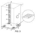
- the arrays are on an electrically insulating mat 18, typically mounted on the internal base 3 of the casing 1 of the SCM and extending up a side wall of the SCM.
- each array is printed in copper on to a flexible printed wiring board and then gold plated for protection against corrosion, the board being mounted on a frame.
- the mat is divided into four sections, a lower section with a first electrode array 19, including a horizontal portion 19a on an electrically insulating mat on the base 3 at or near a corner of the casing 1, and a vertical portion, with the latter rising to a quarter of the height of the SCM.
- the other three sections have respective electrode arrays 20, 21 and 22 and cover half, three quarters and the top quarter of the height of the SCM, resulting in four vertical detection zones.
- Three other small horizontal gold plated electrode arrays with interleaved electrode pairs in the form of arrays 23, 24 and 25 are also mounted on the SCM base 3 on electrically insulating mats, at or near each of the other three corners respectively.
- the electrode pairs of each of the detection zones and the three corner mats are connected to conditioning and detection circuitry housed in the SEM within the SCM.
- the vertical arrays 19 to 22 provide a measure of the quantity of ingress of undesirable fluid into the SCM, i.e. up to a quarter, half, three quarters and full displacement of the original insulating oil by sea-water or hydraulic fluid or both.
- the electrode array 19 by virtue of portion 19a, and the electrode arrays 19, 23, 24 and 25 provide early detection of small quantities of sea-water and/or hydraulic fluid ingress even when the installation of the SCM is not truly vertical and are typically connected in parallel to the conditioning and detection circuitry and treated as one array.
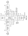
- Fig. 4 shows a block diagram of the conditioning and detection circuitry for the detection of fluid ingress using changes of resistance between the electrodes of the arrays.
- Ingress of sea water will also be detected by the system as only a small amount of ingress will cover at least one of the arrays of the mats on the SCM base and reduce the resistance between the electrodes of the array to only a few tens of ohms.
- the electrode pair on each mat for example that of array 19, is fed from a low voltage DC source 26, typically 2 volts, via a current measuring resistor 27 and isolator switches 28 and 29.
- the current flow through the electrode pair produces a voltage fed to a differential amplifier 30, which produces an analogue output, converted to a digital message that is added to the well monitoring telemetry, fed topside, via the well umbilical.
- the other arrays 20-25 are selected in turn by isolator switches similar to 29 of Fig. 4 .
- the connection of the low voltage source 26 to the arrays is controlled by the isolator switch 28, which is operated by a digital control system also located typically in the SEM.
- the isolator switch 26 is closed only for a brief period, just long enough for the conditioning and detection circuitry to make a measurement, and repeated infrequently. Since the ingress of fluid is typically a slow process, measurement cycle time to measurement execution time ratios in excess of 10,000 to 1 are adequate. This reduces the corrosion of the electrode pairs on a mat due to electrolytic action to a negligible level.
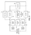
- Fig. 5 shows a block diagram of alternative conditioning and detection circuitry for the detection of fluid ingress utilising the change of capacitance between the electrode pair on any of the mats.
- This method can also be employed as an addition to the resistance measuring method, to provide greater confidence to the well operator that the detection of hydraulic fluid ingress, in particular, is accurate.
- a low voltage AC source is connected across two of the arms of a bridge circuit comprising three capacitors 35, 36 and 37 and the electrode pair of array 19, with two isolator switches 38 and 39. The other two arms of the bridge are connected to AC amplification and detection circuitry 40, to produce a DC output which is fed to the telemetry system of the well.
- the values of the capacitors 35, 36 and 37 are chosen to match the capacitance between the electrode pair of array 19 when immersed in the oil within the SCM, so that the bridge circuit is balanced and there is no output to the circuitry 40. Ingress of hydraulic fluid into the SCM results in a change of capacitance between the electrode pair of array 19 and thus an AC output from the bridge and into the amplification and detection circuitry 40, which in turn produces an output to the well telemetry system.
- a variation of this method is to electronically adjust the value of the capacitor 36, to maintain the balance of the bridge, i.e. zero output from the amplification and detection circuitry 40, and use a measure of the bridge balancing capacitance as the source to the well telemetry system.
- the arrays 19, 23, 24 and 25 are typically connected in parallel to the conditioning and detection circuitry and treated as one array and monitoring of other zones achieved by selecting the arrays 20, 21 and 22 by additional isolator switches.
- Fig. 6 shows a block diagram of an alternative method of detecting a change of capacitance due to undesirable fluid ingress.
- This method utilises the change of capacitance between the electrodes of array 19, resulting from the change of dielectric constant of the fluid it is immersed in, when there is ingress of sea-water and /or hydraulic fluid.
- the change of capacitance results in a change of frequency of an oscillator 41 which can be measured and translated into a DC output using a frequency measuring circuit 42, such as a discriminator and detector, as an output to the well telemetry system.
- the array 19 is selected by isolator switches 38 and 39 and different zones can be monitored by further isolator switches selecting the arrays.
- the arrays 19, 23, 24 and 25 are typically connected in parallel to the conditioning and detection circuitry and treated as one array, and monitoring of other zones achieved by selecting the arrays 20, 21 and 22 by additional isolator switches.
- Leakage of hydraulic fluid in the SCM results in an increase in pressure within the outer casing 1.
- This can be monitored, typically, by a diaphragm type pressure sensor 43, mounted on the wall of the SCM outer casing 1, and connected to the SEM within the SCM and its output also fed into the well monitoring telemetry system.
- the detection of hydraulic fluid ingress by the methods described above can thus be supported by a change of pressure, giving greater confidence of the detection process to the well operator.
- An alternative or additional method of monitoring leakage of hydraulic fluid into the SCM, to provide even greater corroboration of the electrical detection method, is to fit a differential pressure release valve and a flowmeter to the SCM casing as illustrated in Fig. 7 .
- the pressure release valve 44 is set, typically, to open when the pressure in the SCM exceeds the external environmental pressure by 5 psi, resulting from a hydraulic fluid leak.
- the valve 44 opens the flow of liquid from the SCM to the environment is detected by the flowmeter 45, whose electrical output is connected to the well monitoring telemetry system, thus advising the well operator to a fluid leak.
- the key advantage is that the invention permits detection of hydraulic fluid leakage within the SCM in the absence of sea water ingress, and provides an indication of the degree of leakage, neither of which are possible with existing SCM ingress fluid ingress detection systems. Furthermore the system detects the ingress of sea water as well. Corrosion of the detection electrodes is also virtually eliminated.
Landscapes
- Life Sciences & Earth Sciences (AREA)
- Engineering & Computer Science (AREA)
- Geology (AREA)
- Mining & Mineral Resources (AREA)
- Physics & Mathematics (AREA)
- General Life Sciences & Earth Sciences (AREA)
- Environmental & Geological Engineering (AREA)
- Fluid Mechanics (AREA)
- Geochemistry & Mineralogy (AREA)
- Geophysics (AREA)
- Remote Sensing (AREA)
- General Physics & Mathematics (AREA)
- Investigating Or Analyzing Materials By The Use Of Electric Means (AREA)
- Fluid-Pressure Circuits (AREA)
- Examining Or Testing Airtightness (AREA)
Abstract
Description
- The present invention relates to monitoring of undesirable fluid ingress into subsea control modules.
- The hydraulic and electronic components of a subsea well, such as a hydrocarbon extraction well, are typically housed in a sealed vessel termed a subsea control module (SCM), located on a Christmas tree which is mounted on the sea bed above the well bore. An SCM is, typically filled with electrically insulating oil, to alleviate the need to design it to withstand high pressures and provide a first line of defence for the control system against the sea water environment. Typically, an SCM houses hydraulic manifolds, directional control valves and a subsea electronics module (SEM) which is itself a sealed unit. Thus, ingress of sea water resulting from a leak in the SCM housing, or ingress of hydraulic fluid from a small leak in the hydraulic system, will not in itself cause a malfunction of the control system. However, well operators, historically, have needed to know if there is a sea water leak since this will result in corrosion of the components in the SCM and possible failure of the system earlier than expected.
- Existing arrangements consist of sets of metal electrode pairs mounted on an insulating panel or a metal frame with insulating inserts within the SCM, typically four, at equal intervals between the bottom and the top, each connected to an operational amplifier via a low voltage source and a series resistor, thus enabling the detection of the presence of the ingress of electrically conductive sea water, and, in a crude manner, the degree of displacement of the original oil filling. A typical application of the technique is illustrated diagrammatically in
Fig. 1 in which acasing 1 of an SCM is shown as a transparent outline to show an electrically insulatingpanel 2, mounted on thebase 3 of the SCM, withpairs 4 of electrodes mounted on it.Fig. 2 showscircuitry 5 around anoperational amplifier 6, typically housed in the SEM within the SCM, to which the electrode pairs, are connected. Since the resistance across a pair of electrodes when in contact with sea water is very low, i.e. effectively a short circuit, they are shown in ablock 7 assimple switch contacts circuit 5 is the ratio of the resistance of afeedback resistor 12 acrossamplifier 6 and the effective resistance provided byinput resistors electrode pairs 4 and an input ofamplifier 6. Each of the input resistors is chosen to be of a resistance which is one quarter of that of thefeedback resistor 12. Thus, if there is water ingress into thecasing 1 to the level of the lowest electrode pair, then thecontacts 8 of theblock 7 are effectively closed and theoutput 17 of theoperational amplifier 6 will rise to ¼ of V. Likewise, further ingress of sea water reaching the remaining electrode pairs will result in theoutput 17 rising to ½ V, ¾ V and V respectively as thecontacts output 17 of thecircuit 5 and transmitting the information topside, as a digitised version of the analogue signal, to the well operator, typically via the well umbilical, as part of the well housekeeping/ diagnostic telemetry. - A problem with the existing technique is that it is unable to detect the ingress of hydraulic fluid into the SCM resulting from a leak in the hydraulic system in the SCM. Currently, a well operator has relied on hydraulic fluid leak detectors at the fluid source but these cannot confirm whether the leak is actually within the SCM. A further problem is that current flow through the electrode pairs results in their corrosion.
- This invention enables the detection of both the ingress of sea water and hydraulic fluid in the SCM and provides a better indication of the degree of ingress, and reduces corrosion of the sensing electrodes.
- Recent measurements have been made in the laboratory of the change in conductivity of the insulating oil in an SCM with contamination by the hydraulic fluid used for the well control system, which is a glycol based trans-aqua fluid. Results show that the conductivity of the contaminate in the oil is much less than that due to sea water and thus the existing contamination detection technique described before was not sensitive enough to be able to detect the ingress of trans-aqua fluids. Measurements have also shown that sea-water and trans-aqua hydraulic fluid (glycol) in insulating oil result in an immiscible fluid with both contaminants having a greater density than the oil. Thus, ingress of these contaminants displaces the transformer oil from the base of the SCM upwards. This invention provides an improved method for the monitoring of undesirable fluid ingress into an SCM to enable detection of the ingress of trans-aqua hydraulic fluid as well as sea water, whilst still providing a zoned measure of the degree of ingress and using a variety of methods of measurement which also reduces, substantially, corrosion of sensing electrode pairs.
- According to the present invention from one aspect, there is provided a subsea control module having a casing inside which there is at least one pair of electrodes, there being electronic means connected with the electrodes of the or each pair for monitoring at least one electrical characteristic between the electrodes as a result of a fluid to which the electrodes are exposed, wherein the or each pair of electrodes comprises an array in which each electrode of the pair has finger portions interleaved with finger portions of the other electrode.
- There could be at least one such array on a base of the casing. Preferably, there is a plurality of such arrays on the base of the casing, each of which, for example, is at or near a respective corner of the casing.
- Preferably, there is such an array disposed on a side wall of the casing and covering a zone of the side wall. In this case, said array disposed on a side wall could cover a lower zone of the side wall, which array, for example, also covers a portion of the base of the casing. Said portion of the base of the casing could be at or near a corner of the casing.
- Preferably, there is at least one further such array after said array disposed on a side wall of the casing, the or each further such array covering a respective zone up the side wall of the casing.
- Said at least one electrical characteristic could comprise at least one of resistance and capacitance.
- Preferably, the or each array is disposed on a mat of electrically insulating material.
- Preferably, said electronic means is provided by a subsea electronics module of the control module.
- According to the present invention from another aspect, there is provided a subsea control module having a casing inside which there are a plurality of electrode pairs, there being electronic means connected with the electrodes of each pair for monitoring at least one electrical characteristic between the electrodes of the pair as a result of a fluid to which the electrodes are exposed, wherein said electrode pairs are disposed on a base of the casing.
- Preferably, there are also a plurality of further electrode pairs, each of which covers a respective zone up a side wall of the casing, said electronic control means being connected with the electrodes of each of the further electrode pairs.
- Preferably, for both aspects of the invention, the electronic means applies a signal between the electrodes of the or each pair of electrodes for selected periods of time at selected intervals.
- A module according to the invention could include pressure sensing means for sensing the pressure of fluid in the casing for use in providing an indication of an increase in pressure due to fluid leakage within the casing.
- A module according to the invention could include release means for releasing fluid from the casing in response to an increase in fluid pressure within the casing above a threshold.
- There could be a flowmeter coupled with said release means for providing an indication of the release of fluid.
- According to the present invention from a further aspect, there is provided a subsea control module having a casing inside which there is at least one electrode pair, there being electronic means connected with the electrodes of the or each pair for monitoring at least one electrical characteristic between the electrodes of the pair as a result of a fluid to which the electrodes are exposed, wherein said electronic means applies a signal between the electrodes of the or each pair of electrodes for selected periods of time at selected intervals.
- According to the present invention from yet a further aspect, there is provided a subsea control module including pressure sensing means for sensing the pressure of fluid in a casing of the module for use in providing an indication of an increase in pressure due to fluid leakage within the casing.
- According to the present invention from yet a further aspect, there is provided a subsea control module including release means for releasing fluid from a casing of the module in response to an increase in fluid pressure within the casing above a threshold.
-
-
Fig. 1 illustrates a prior art system; -
Fig. 2 illustrates circuitry for use with the system ofFig. 1 ; -
Fig. 3 illustrates a system according to an embodiment of the invention; -
Figs. 4 ,5 and6 illustrate forms of circuitry for use with the system ofFig. 3 ; and -
Fig. 7 shows how pressure release means can be provided. - Referring to
Fig. 3 , the individual electrode pairs of the system ofFig. 1 are replaced with electrode pairs, in each of which each electrode of the pair has finger portions interleaved or interlaced with finger portions of the other electrode to form an electrode array. The arrays are on an electrically insulatingmat 18, typically mounted on theinternal base 3 of thecasing 1 of the SCM and extending up a side wall of the SCM. Typically, each array is printed in copper on to a flexible printed wiring board and then gold plated for protection against corrosion, the board being mounted on a frame. The mat is divided into four sections, a lower section with afirst electrode array 19, including ahorizontal portion 19a on an electrically insulating mat on thebase 3 at or near a corner of thecasing 1, and a vertical portion, with the latter rising to a quarter of the height of the SCM. The other three sections haverespective electrode arrays arrays SCM base 3 on electrically insulating mats, at or near each of the other three corners respectively. The electrode pairs of each of the detection zones and the three corner mats are connected to conditioning and detection circuitry housed in the SEM within the SCM. Thevertical arrays 19 to 22 provide a measure of the quantity of ingress of undesirable fluid into the SCM, i.e. up to a quarter, half, three quarters and full displacement of the original insulating oil by sea-water or hydraulic fluid or both. Theelectrode array 19 by virtue ofportion 19a, and theelectrode arrays -
Fig. 4 shows a block diagram of the conditioning and detection circuitry for the detection of fluid ingress using changes of resistance between the electrodes of the arrays. With the SCM filled with clean, uncontaminated oil, the resistance between the terminals of any of theelectrode array 19 to 25 is very high, typically tens of megohms. With a small ingress of trans-aqua fluid, e.g. enough to cover arrays on the mats mounted on the SCM housing base, the resistance will fall typically to a few hundred kilohms. Ingress of sea water will also be detected by the system as only a small amount of ingress will cover at least one of the arrays of the mats on the SCM base and reduce the resistance between the electrodes of the array to only a few tens of ohms. The electrode pair on each mat, for example that ofarray 19, is fed from a lowvoltage DC source 26, typically 2 volts, via acurrent measuring resistor 27 and isolator switches 28 and 29. The current flow through the electrode pair produces a voltage fed to adifferential amplifier 30, which produces an analogue output, converted to a digital message that is added to the well monitoring telemetry, fed topside, via the well umbilical. Although only one electrode array (19) is shown inFig. 4 , the other arrays 20-25 are selected in turn by isolator switches similar to 29 ofFig. 4 . The connection of thelow voltage source 26 to the arrays is controlled by theisolator switch 28, which is operated by a digital control system also located typically in the SEM. Theisolator switch 26 is closed only for a brief period, just long enough for the conditioning and detection circuitry to make a measurement, and repeated infrequently. Since the ingress of fluid is typically a slow process, measurement cycle time to measurement execution time ratios in excess of 10,000 to 1 are adequate. This reduces the corrosion of the electrode pairs on a mat due to electrolytic action to a negligible level. The process described above is repeated for the detection of sea-water ingress, by the samelow voltage source 26, connected to the arrays via acurrent measuring resistor 31 and anisolator switch 32, producing an output to the well telemetry system from adifferential amplifier 33. Since the resistance between the electrode pairs on mats resulting from hydraulic fluid ingress is much greater (kilohms) than that resulting from sea water ingress (tens of ohms), the value of the measuringresistor 27 is much greater than theresistor 31 to produce a greater detection circuitry gain. Although the ingress of sea-water will swamp the hydraulic fluid ingress detection circuitry, this is of little concern since the detection of sea water ingress is itself sufficiently serious to warrant corrective action by the well operator. -
Fig. 5 shows a block diagram of alternative conditioning and detection circuitry for the detection of fluid ingress utilising the change of capacitance between the electrode pair on any of the mats. This method can also be employed as an addition to the resistance measuring method, to provide greater confidence to the well operator that the detection of hydraulic fluid ingress, in particular, is accurate. A low voltage AC source is connected across two of the arms of a bridge circuit comprising threecapacitors array 19, with twoisolator switches detection circuitry 40, to produce a DC output which is fed to the telemetry system of the well. The values of thecapacitors array 19 when immersed in the oil within the SCM, so that the bridge circuit is balanced and there is no output to thecircuitry 40. Ingress of hydraulic fluid into the SCM results in a change of capacitance between the electrode pair ofarray 19 and thus an AC output from the bridge and into the amplification anddetection circuitry 40, which in turn produces an output to the well telemetry system. A variation of this method is to electronically adjust the value of thecapacitor 36, to maintain the balance of the bridge, i.e. zero output from the amplification anddetection circuitry 40, and use a measure of the bridge balancing capacitance as the source to the well telemetry system. Again, thearrays arrays -
Fig. 6 shows a block diagram of an alternative method of detecting a change of capacitance due to undesirable fluid ingress. This method utilises the change of capacitance between the electrodes ofarray 19, resulting from the change of dielectric constant of the fluid it is immersed in, when there is ingress of sea-water and /or hydraulic fluid. The change of capacitance results in a change of frequency of anoscillator 41 which can be measured and translated into a DC output using afrequency measuring circuit 42, such as a discriminator and detector, as an output to the well telemetry system. Thearray 19 is selected byisolator switches arrays arrays - Leakage of hydraulic fluid in the SCM results in an increase in pressure within the
outer casing 1. This can be monitored, typically, by a diaphragmtype pressure sensor 43, mounted on the wall of the SCMouter casing 1, and connected to the SEM within the SCM and its output also fed into the well monitoring telemetry system. The detection of hydraulic fluid ingress by the methods described above can thus be supported by a change of pressure, giving greater confidence of the detection process to the well operator. - An alternative or additional method of monitoring leakage of hydraulic fluid into the SCM, to provide even greater corroboration of the electrical detection method, is to fit a differential pressure release valve and a flowmeter to the SCM casing as illustrated in
Fig. 7 . Thepressure release valve 44, is set, typically, to open when the pressure in the SCM exceeds the external environmental pressure by 5 psi, resulting from a hydraulic fluid leak. When thevalve 44 opens the flow of liquid from the SCM to the environment is detected by theflowmeter 45, whose electrical output is connected to the well monitoring telemetry system, thus advising the well operator to a fluid leak. - The key advantage is that the invention permits detection of hydraulic fluid leakage within the SCM in the absence of sea water ingress, and provides an indication of the degree of leakage, neither of which are possible with existing SCM ingress fluid ingress detection systems. Furthermore the system detects the ingress of sea water as well. Corrosion of the detection electrodes is also virtually eliminated.
Claims (18)
- A subsea control module having a casing inside which there is at least one pair of electrodes, there being electronic means connected with the electrodes of the or each pair for monitoring at least one electrical characteristic between the electrodes as a result of a fluid to which the electrodes are exposed, wherein the or each pair of electrodes comprises an array in which each electrode of the pair has finger portions interleaved with finger portions of the other electrode.
- A control module according to claim 1, wherein there is at least one such array on a base of the casing.
- A control module according to claim 2, wherein there is a plurality of such arrays on the base of the casing.
- A control module according to claim 3, wherein each of said plurality of such arrays is at or near a respective corner of the casing.
- A control module according to any preceding claim, wherein there is such an array disposed on a side wall of the casing and covering a zone of the side wall.
- A control module according to claim 5, wherein said array disposed on a side wall covers a lower zone of the side wall.
- A control module according to claim 6, wherein said array disposed on a side wall also covers a portion of the base of the casing.
- A control module according to claim 7, wherein said portion of the base of the casing is at or near a corner of the casing.
- A control module according to any of claims 5 to 8, wherein there is at least one further such array after said array disposed on a side wall of the casing, the or each further such array covering a respective zone up the side wall of the casing.
- A subsea control module having a casing inside which there are a plurality of electrode pairs, there being electronic means connected with the electrodes of each pair for monitoring at least one electrical characteristic between the electrodes of the pair as a result of a fluid to which the electrodes are exposed, wherein said electrode pairs are disposed on a base of the casing.
- A control module according to claim 10, wherein there are a plurality of further electrode pairs, each of which covers a respective zone up a side wall of the casing, said electronic control means being connected with the electrodes of each of the further electrode pairs.
- A control module according to any preceding claim, wherein said at least one electrical characteristic comprises at least one of resistance and capacitance.
- A control module according to any preceding claim, wherein the or each array is disposed on a mat of electrically insulating material.
- A control module according to any preceding claim, wherein said electronic means is provided by a subsea electronics module of the control module.
- A control module according to any preceding claim, wherein said electronic means applies a signal between the electrodes of the or each pair of electrodes for selected periods of time at selected intervals.
- A control module according to any preceding claim, including pressure sensing means for sensing the pressure of fluid in the casing for use in providing an indication of an increase in pressure due to fluid leakage within the casing.
- A control module according to any preceding claim, including release means for releasing fluid from the casing in response to an increase in fluid pressure within the casing above a threshold.
- A control module according to claim 17, including a flowmeter coupled with said release means for providing an indication of the release of fluid.
Applications Claiming Priority (1)
| Application Number | Priority Date | Filing Date | Title |
|---|---|---|---|
| GB0910426.6A GB2471108B (en) | 2009-06-17 | 2009-06-17 | Monitoring of undesirable fluid ingress into subsea control modules |
Publications (3)
| Publication Number | Publication Date |
|---|---|
| EP2278121A2 true EP2278121A2 (en) | 2011-01-26 |
| EP2278121A3 EP2278121A3 (en) | 2016-11-09 |
| EP2278121B1 EP2278121B1 (en) | 2019-11-27 |
Family
ID=40940950
Family Applications (1)
| Application Number | Title | Priority Date | Filing Date |
|---|---|---|---|
| EP10161144.0A Active EP2278121B1 (en) | 2009-06-17 | 2010-04-27 | Monitoring of undesirable fluid ingress into subsea control modules |
Country Status (7)
| Country | Link |
|---|---|
| US (2) | US8427336B2 (en) |
| EP (1) | EP2278121B1 (en) |
| CN (1) | CN101929912B (en) |
| BR (1) | BRPI1001627B1 (en) |
| GB (2) | GB2478232B (en) |
| MY (1) | MY155099A (en) |
| SG (1) | SG186626A1 (en) |
Families Citing this family (12)
| Publication number | Priority date | Publication date | Assignee | Title |
|---|---|---|---|---|
| GB2478232B (en) | 2009-06-17 | 2011-12-07 | Vetco Gray Controls Ltd | Monitoring of undesirable fluid ingress into subsea control modules |
| EP2513614A1 (en) * | 2009-12-17 | 2012-10-24 | BAE Systems Plc. | Sensors |
| US9108423B2 (en) * | 2011-05-31 | 2015-08-18 | Funai Electric Co., Ltd. | Consumable supply item with fluid sensing for micro-fluid applications |
| CN104236812B (en) * | 2013-06-09 | 2017-02-22 | 同济大学 | A method and device for detecting water seepage in tunnels based on electrical conductivity |
| WO2015082007A1 (en) | 2013-12-05 | 2015-06-11 | Abb Technology Ltd | Measurements in a subsea installation |
| US9970833B2 (en) * | 2014-04-23 | 2018-05-15 | The Boeing Company | Witness material and method for monitoring the environmental history of an object |
| CN104949805B (en) * | 2014-12-03 | 2018-11-23 | 佛山市云米电器科技有限公司 | leakage detection method and device |
| GB2552004A (en) * | 2016-07-06 | 2018-01-10 | The Magstim Company Ltd | Magnetic stimulation coil arrangment including coolant leak detector |
| CN110006596B (en) * | 2019-04-20 | 2021-04-06 | 清华大学 | A static seal leak detection device |
| CN110243550B (en) * | 2019-06-11 | 2024-08-02 | 中国地质大学(武汉) | Cavity seepage monitoring device |
| CN111060258A (en) * | 2019-12-04 | 2020-04-24 | 大连融科储能装备有限公司 | Liquid receiving tank for leakage detection in flow battery system, leakage detection system and early warning and mounting method |
| KR102635185B1 (en) * | 2023-09-19 | 2024-02-08 | 주식회사 이도 | Earth surface water level measuring device |
Family Cites Families (25)
| Publication number | Priority date | Publication date | Assignee | Title |
|---|---|---|---|---|
| US2668202A (en) * | 1952-08-02 | 1954-02-02 | Benjamin D Kaplan | Moisture responsive signaling device |
| US2919579A (en) * | 1955-07-26 | 1960-01-05 | Liquidometer Corp | Electrically-conductive liquid level measuring system |
| US3703207A (en) * | 1970-07-29 | 1972-11-21 | Deep Oil Technology Inc | Subsea bunker construction |
| US4230187A (en) * | 1979-06-19 | 1980-10-28 | Trw Inc. | Methods and apparatus for sensing wellhead pressure |
| JPS60169719A (en) * | 1984-02-14 | 1985-09-03 | Nippon Soken Inc | Physical quantity detecting apparatus |
| GB8626884D0 (en) * | 1986-11-11 | 1986-12-10 | Myrmidon Subsea Controls Ltd | Subsea systems & devices |
| GB2246866A (en) * | 1990-08-06 | 1992-02-12 | Texaco Development Corp | Borehole water content logging system and method |
| US5050431A (en) * | 1990-09-12 | 1991-09-24 | Robertshaw Controls Company | Liquid level sensing device and methods of making an operating the same |
| GB2285819B (en) * | 1994-01-25 | 1997-07-16 | Brisco Eng Ltd | A manifold arrangement |
| US6335690B1 (en) * | 1997-01-15 | 2002-01-01 | Algonquin Scientific, Llc | Fluid sensing system |
| JP2000517061A (en) * | 1997-06-12 | 2000-12-19 | マチュレック,アンドリュウ,エム. | Liquid level indicator |
| GB9721929D0 (en) * | 1997-10-17 | 1997-12-17 | Overfield Timothy M | Novel control system |
| US6679332B2 (en) * | 2000-01-24 | 2004-01-20 | Shell Oil Company | Petroleum well having downhole sensors, communication and power |
| CN1387035A (en) * | 2001-05-18 | 2002-12-25 | 张钢柱 | Method and device for testing quality of oil liquid |
| US6640900B2 (en) * | 2001-07-12 | 2003-11-04 | Sensor Highway Limited | Method and apparatus to monitor, control and log subsea oil and gas wells |
| US7373817B2 (en) * | 2004-07-09 | 2008-05-20 | Touchsensor Technologies, Llc | Solid state fluid level sensor |
| US7216714B2 (en) * | 2004-08-20 | 2007-05-15 | Oceaneering International, Inc. | Modular, distributed, ROV retrievable subsea control system, associated deepwater subsea blowout preventer stack configuration, and methods of use |
| US7255004B2 (en) * | 2004-09-13 | 2007-08-14 | United States Of America As Represented By The Administrator Of The National Aeronautics And Space Administration | Wireless fluid level measuring system |
| GB2428436A (en) * | 2005-07-15 | 2007-01-31 | Vetco Gray Controls Ltd | Underwater module with conformal waterproof coating |
| US7506541B2 (en) * | 2006-01-09 | 2009-03-24 | The United States Of America As Represented By The National Aeronautics And Space Administration | System and method for wirelessly determining fluid volume |
| US7918126B2 (en) * | 2007-09-26 | 2011-04-05 | Fmc Technologies, Inc. | Intelligent underwater leak detection system |
| CN101206154A (en) * | 2007-12-12 | 2008-06-25 | 浙江理工大学 | Leak detection method of oil-immersed submersible pump seal cavity |
| US7845404B2 (en) * | 2008-09-04 | 2010-12-07 | Fmc Technologies, Inc. | Optical sensing system for wellhead equipment |
| CN101571234B (en) * | 2009-06-16 | 2012-05-30 | 北京埃德尔黛威新技术有限公司 | Liquid pressure conduit leak detection device |
| GB2478232B (en) | 2009-06-17 | 2011-12-07 | Vetco Gray Controls Ltd | Monitoring of undesirable fluid ingress into subsea control modules |
-
2009
- 2009-06-17 GB GB1109611A patent/GB2478232B/en not_active Expired - Fee Related
- 2009-06-17 GB GB0910426.6A patent/GB2471108B/en not_active Expired - Fee Related
-
2010
- 2010-04-27 EP EP10161144.0A patent/EP2278121B1/en active Active
- 2010-04-30 SG SG2012089603A patent/SG186626A1/en unknown
- 2010-05-31 BR BRPI1001627A patent/BRPI1001627B1/en not_active IP Right Cessation
- 2010-06-07 MY MYPI2010002611A patent/MY155099A/en unknown
- 2010-06-16 US US12/816,734 patent/US8427336B2/en not_active Expired - Fee Related
- 2010-06-17 CN CN201010203650.8A patent/CN101929912B/en not_active Expired - Fee Related
-
2013
- 2013-03-20 US US13/847,510 patent/US8711002B2/en not_active Expired - Fee Related
Non-Patent Citations (1)
| Title |
|---|
| None |
Also Published As
| Publication number | Publication date |
|---|---|
| US8427336B2 (en) | 2013-04-23 |
| BRPI1001627A8 (en) | 2016-04-12 |
| EP2278121B1 (en) | 2019-11-27 |
| GB201109611D0 (en) | 2011-07-20 |
| GB0910426D0 (en) | 2009-07-29 |
| US8711002B2 (en) | 2014-04-29 |
| GB2471108A (en) | 2010-12-22 |
| US20110018733A1 (en) | 2011-01-27 |
| EP2278121A3 (en) | 2016-11-09 |
| GB2478232A (en) | 2011-08-31 |
| AU2010202483A1 (en) | 2011-01-13 |
| BRPI1001627B1 (en) | 2019-08-13 |
| SG186626A1 (en) | 2013-01-30 |
| US20130214933A1 (en) | 2013-08-22 |
| MY155099A (en) | 2015-09-15 |
| GB2478232B (en) | 2011-12-07 |
| GB2471108B (en) | 2013-08-07 |
| BRPI1001627A2 (en) | 2011-07-26 |
| CN101929912B (en) | 2015-02-25 |
| CN101929912A (en) | 2010-12-29 |
Similar Documents
| Publication | Publication Date | Title |
|---|---|---|
| EP2278121B1 (en) | Monitoring of undesirable fluid ingress into subsea control modules | |
| US4446730A (en) | Specific gravity independent gauging of liquid filled tanks | |
| US9869600B2 (en) | Pressure sensor | |
| US20100295565A1 (en) | Automated phase separation and fuel quality sensor | |
| EP2663843A1 (en) | Device for measuring fluid level in a container | |
| CN105026899A (en) | Method and apparatus for monitoring a predefined filling level of a medium in a container | |
| CA1229501A (en) | Level gauge | |
| CN102288651A (en) | Capacitance sensor for detecting moisture content of static crude oil | |
| US5860316A (en) | Capacitance probe | |
| WO2000043735A2 (en) | Method and apparatus for measuring fluid levels in vessels | |
| US10732065B2 (en) | Apparatus and method of detecting breaches in pipelines | |
| KR20200105708A (en) | Device for capacitive measurements in multiphase media | |
| RU2695588C1 (en) | Method of measuring liquid level and device for its implementation (versions) | |
| JPH06137982A (en) | Pressure transmitter | |
| RU2834510C1 (en) | Device and method for automated measurement of drilling mud parameters | |
| CN203053914U (en) | Gas sensor | |
| Tiwari et al. | Implementation of capacitive fluid level sensor | |
| KR200340501Y1 (en) | Fluid Detector Sensor Unit and Fluid Detector Sensor | |
| CN120427085A (en) | Liquid level measuring device and liquid level measuring sensor | |
| RU64360U1 (en) | DEVICE FOR MEASURING THE LEVELS OF THE BOUNDARIES OF THE SECTION OF THE MEDIUM | |
| GB2055475A (en) | Electronic sight glass gauging | |
| CS203582B1 (en) | Device for indication of the oily substances on the surface of fluids | |
| EP3077835A1 (en) | Measurements in a subsea installation |
Legal Events
| Date | Code | Title | Description |
|---|---|---|---|
| PUAI | Public reference made under article 153(3) epc to a published international application that has entered the european phase |
Free format text: ORIGINAL CODE: 0009012 |
|
| AK | Designated contracting states |
Kind code of ref document: A2 Designated state(s): AT BE BG CH CY CZ DE DK EE ES FI FR GB GR HR HU IE IS IT LI LT LU LV MC MK MT NL NO PL PT RO SE SI SK SM TR |
|
| AX | Request for extension of the european patent |
Extension state: AL BA ME RS |
|
| RAP1 | Party data changed (applicant data changed or rights of an application transferred) |
Owner name: GE OIL & GAS UK LIMITED |
|
| PUAL | Search report despatched |
Free format text: ORIGINAL CODE: 0009013 |
|
| AK | Designated contracting states |
Kind code of ref document: A3 Designated state(s): AT BE BG CH CY CZ DE DK EE ES FI FR GB GR HR HU IE IS IT LI LT LU LV MC MK MT NL NO PL PT RO SE SI SK SM TR |
|
| AX | Request for extension of the european patent |
Extension state: AL BA ME RS |
|
| RIC1 | Information provided on ipc code assigned before grant |
Ipc: E21B 47/00 20120101AFI20161005BHEP Ipc: E21B 33/035 20060101ALI20161005BHEP Ipc: E21B 47/10 20120101ALI20161005BHEP |
|
| STAA | Information on the status of an ep patent application or granted ep patent |
Free format text: STATUS: REQUEST FOR EXAMINATION WAS MADE |
|
| 17P | Request for examination filed |
Effective date: 20170509 |
|
| RBV | Designated contracting states (corrected) |
Designated state(s): AT BE BG CH CY CZ DE DK EE ES FI FR GB GR HR HU IE IS IT LI LT LU LV MC MK MT NL NO PL PT RO SE SI SK SM TR |
|
| STAA | Information on the status of an ep patent application or granted ep patent |
Free format text: STATUS: EXAMINATION IS IN PROGRESS |
|
| 17Q | First examination report despatched |
Effective date: 20170925 |
|
| GRAP | Despatch of communication of intention to grant a patent |
Free format text: ORIGINAL CODE: EPIDOSNIGR1 |
|
| STAA | Information on the status of an ep patent application or granted ep patent |
Free format text: STATUS: GRANT OF PATENT IS INTENDED |
|
| INTG | Intention to grant announced |
Effective date: 20190318 |
|
| RIN1 | Information on inventor provided before grant (corrected) |
Inventor name: GILL, SIMON DAVID Inventor name: DAVIS, JULIAN R. Inventor name: DERRICK, ADRIAN JOHN |
|
| GRAS | Grant fee paid |
Free format text: ORIGINAL CODE: EPIDOSNIGR3 |
|
| GRAA | (expected) grant |
Free format text: ORIGINAL CODE: 0009210 |
|
| STAA | Information on the status of an ep patent application or granted ep patent |
Free format text: STATUS: THE PATENT HAS BEEN GRANTED |
|
| AK | Designated contracting states |
Kind code of ref document: B1 Designated state(s): AT BE BG CH CY CZ DE DK EE ES FI FR GB GR HR HU IE IS IT LI LT LU LV MC MK MT NL NO PL PT RO SE SI SK SM TR |
|
| REG | Reference to a national code |
Ref country code: GB Ref legal event code: FG4D |
|
| REG | Reference to a national code |
Ref country code: CH Ref legal event code: EP |
|
| REG | Reference to a national code |
Ref country code: AT Ref legal event code: REF Ref document number: 1206854 Country of ref document: AT Kind code of ref document: T Effective date: 20191215 |
|
| REG | Reference to a national code |
Ref country code: DE Ref legal event code: R096 Ref document number: 602010062107 Country of ref document: DE |
|
| REG | Reference to a national code |
Ref country code: IE Ref legal event code: FG4D |
|
| REG | Reference to a national code |
Ref country code: NO Ref legal event code: T2 Effective date: 20191127 |
|
| REG | Reference to a national code |
Ref country code: NL Ref legal event code: MP Effective date: 20191127 |
|
| REG | Reference to a national code |
Ref country code: LT Ref legal event code: MG4D |
|
| PG25 | Lapsed in a contracting state [announced via postgrant information from national office to epo] |
Ref country code: LV Free format text: LAPSE BECAUSE OF FAILURE TO SUBMIT A TRANSLATION OF THE DESCRIPTION OR TO PAY THE FEE WITHIN THE PRESCRIBED TIME-LIMIT Effective date: 20191127 Ref country code: ES Free format text: LAPSE BECAUSE OF FAILURE TO SUBMIT A TRANSLATION OF THE DESCRIPTION OR TO PAY THE FEE WITHIN THE PRESCRIBED TIME-LIMIT Effective date: 20191127 Ref country code: GR Free format text: LAPSE BECAUSE OF FAILURE TO SUBMIT A TRANSLATION OF THE DESCRIPTION OR TO PAY THE FEE WITHIN THE PRESCRIBED TIME-LIMIT Effective date: 20200228 Ref country code: LT Free format text: LAPSE BECAUSE OF FAILURE TO SUBMIT A TRANSLATION OF THE DESCRIPTION OR TO PAY THE FEE WITHIN THE PRESCRIBED TIME-LIMIT Effective date: 20191127 Ref country code: BG Free format text: LAPSE BECAUSE OF FAILURE TO SUBMIT A TRANSLATION OF THE DESCRIPTION OR TO PAY THE FEE WITHIN THE PRESCRIBED TIME-LIMIT Effective date: 20200227 Ref country code: NL Free format text: LAPSE BECAUSE OF FAILURE TO SUBMIT A TRANSLATION OF THE DESCRIPTION OR TO PAY THE FEE WITHIN THE PRESCRIBED TIME-LIMIT Effective date: 20191127 Ref country code: SE Free format text: LAPSE BECAUSE OF FAILURE TO SUBMIT A TRANSLATION OF THE DESCRIPTION OR TO PAY THE FEE WITHIN THE PRESCRIBED TIME-LIMIT Effective date: 20191127 Ref country code: FI Free format text: LAPSE BECAUSE OF FAILURE TO SUBMIT A TRANSLATION OF THE DESCRIPTION OR TO PAY THE FEE WITHIN THE PRESCRIBED TIME-LIMIT Effective date: 20191127 |
|
| PGFP | Annual fee paid to national office [announced via postgrant information from national office to epo] |
Ref country code: NO Payment date: 20200320 Year of fee payment: 11 Ref country code: GB Payment date: 20200323 Year of fee payment: 11 |
|
| PG25 | Lapsed in a contracting state [announced via postgrant information from national office to epo] |
Ref country code: HR Free format text: LAPSE BECAUSE OF FAILURE TO SUBMIT A TRANSLATION OF THE DESCRIPTION OR TO PAY THE FEE WITHIN THE PRESCRIBED TIME-LIMIT Effective date: 20191127 Ref country code: IS Free format text: LAPSE BECAUSE OF FAILURE TO SUBMIT A TRANSLATION OF THE DESCRIPTION OR TO PAY THE FEE WITHIN THE PRESCRIBED TIME-LIMIT Effective date: 20200327 |
|
| PGFP | Annual fee paid to national office [announced via postgrant information from national office to epo] |
Ref country code: FR Payment date: 20200319 Year of fee payment: 11 |
|
| PG25 | Lapsed in a contracting state [announced via postgrant information from national office to epo] |
Ref country code: EE Free format text: LAPSE BECAUSE OF FAILURE TO SUBMIT A TRANSLATION OF THE DESCRIPTION OR TO PAY THE FEE WITHIN THE PRESCRIBED TIME-LIMIT Effective date: 20191127 Ref country code: PT Free format text: LAPSE BECAUSE OF FAILURE TO SUBMIT A TRANSLATION OF THE DESCRIPTION OR TO PAY THE FEE WITHIN THE PRESCRIBED TIME-LIMIT Effective date: 20200419 Ref country code: DK Free format text: LAPSE BECAUSE OF FAILURE TO SUBMIT A TRANSLATION OF THE DESCRIPTION OR TO PAY THE FEE WITHIN THE PRESCRIBED TIME-LIMIT Effective date: 20191127 Ref country code: CZ Free format text: LAPSE BECAUSE OF FAILURE TO SUBMIT A TRANSLATION OF THE DESCRIPTION OR TO PAY THE FEE WITHIN THE PRESCRIBED TIME-LIMIT Effective date: 20191127 Ref country code: RO Free format text: LAPSE BECAUSE OF FAILURE TO SUBMIT A TRANSLATION OF THE DESCRIPTION OR TO PAY THE FEE WITHIN THE PRESCRIBED TIME-LIMIT Effective date: 20191127 |
|
| PGFP | Annual fee paid to national office [announced via postgrant information from national office to epo] |
Ref country code: DE Payment date: 20200319 Year of fee payment: 11 |
|
| REG | Reference to a national code |
Ref country code: DE Ref legal event code: R097 Ref document number: 602010062107 Country of ref document: DE |
|
| PG25 | Lapsed in a contracting state [announced via postgrant information from national office to epo] |
Ref country code: SM Free format text: LAPSE BECAUSE OF FAILURE TO SUBMIT A TRANSLATION OF THE DESCRIPTION OR TO PAY THE FEE WITHIN THE PRESCRIBED TIME-LIMIT Effective date: 20191127 Ref country code: SK Free format text: LAPSE BECAUSE OF FAILURE TO SUBMIT A TRANSLATION OF THE DESCRIPTION OR TO PAY THE FEE WITHIN THE PRESCRIBED TIME-LIMIT Effective date: 20191127 |
|
| REG | Reference to a national code |
Ref country code: AT Ref legal event code: MK05 Ref document number: 1206854 Country of ref document: AT Kind code of ref document: T Effective date: 20191127 |
|
| PLBE | No opposition filed within time limit |
Free format text: ORIGINAL CODE: 0009261 |
|
| STAA | Information on the status of an ep patent application or granted ep patent |
Free format text: STATUS: NO OPPOSITION FILED WITHIN TIME LIMIT |
|
| 26N | No opposition filed |
Effective date: 20200828 |
|
| PG25 | Lapsed in a contracting state [announced via postgrant information from national office to epo] |
Ref country code: SI Free format text: LAPSE BECAUSE OF FAILURE TO SUBMIT A TRANSLATION OF THE DESCRIPTION OR TO PAY THE FEE WITHIN THE PRESCRIBED TIME-LIMIT Effective date: 20191127 Ref country code: MC Free format text: LAPSE BECAUSE OF FAILURE TO SUBMIT A TRANSLATION OF THE DESCRIPTION OR TO PAY THE FEE WITHIN THE PRESCRIBED TIME-LIMIT Effective date: 20191127 Ref country code: AT Free format text: LAPSE BECAUSE OF FAILURE TO SUBMIT A TRANSLATION OF THE DESCRIPTION OR TO PAY THE FEE WITHIN THE PRESCRIBED TIME-LIMIT Effective date: 20191127 Ref country code: PL Free format text: LAPSE BECAUSE OF FAILURE TO SUBMIT A TRANSLATION OF THE DESCRIPTION OR TO PAY THE FEE WITHIN THE PRESCRIBED TIME-LIMIT Effective date: 20191127 |
|
| REG | Reference to a national code |
Ref country code: CH Ref legal event code: PL |
|
| PG25 | Lapsed in a contracting state [announced via postgrant information from national office to epo] |
Ref country code: CH Free format text: LAPSE BECAUSE OF NON-PAYMENT OF DUE FEES Effective date: 20200430 Ref country code: IT Free format text: LAPSE BECAUSE OF FAILURE TO SUBMIT A TRANSLATION OF THE DESCRIPTION OR TO PAY THE FEE WITHIN THE PRESCRIBED TIME-LIMIT Effective date: 20191127 Ref country code: LU Free format text: LAPSE BECAUSE OF NON-PAYMENT OF DUE FEES Effective date: 20200427 Ref country code: LI Free format text: LAPSE BECAUSE OF NON-PAYMENT OF DUE FEES Effective date: 20200430 |
|
| REG | Reference to a national code |
Ref country code: BE Ref legal event code: MM Effective date: 20200430 |
|
| PG25 | Lapsed in a contracting state [announced via postgrant information from national office to epo] |
Ref country code: BE Free format text: LAPSE BECAUSE OF NON-PAYMENT OF DUE FEES Effective date: 20200430 |
|
| PG25 | Lapsed in a contracting state [announced via postgrant information from national office to epo] |
Ref country code: IE Free format text: LAPSE BECAUSE OF NON-PAYMENT OF DUE FEES Effective date: 20200427 |
|
| REG | Reference to a national code |
Ref country code: DE Ref legal event code: R119 Ref document number: 602010062107 Country of ref document: DE |
|
| REG | Reference to a national code |
Ref country code: NO Ref legal event code: MMEP |
|
| GBPC | Gb: european patent ceased through non-payment of renewal fee |
Effective date: 20210427 |
|
| PG25 | Lapsed in a contracting state [announced via postgrant information from national office to epo] |
Ref country code: NO Free format text: LAPSE BECAUSE OF NON-PAYMENT OF DUE FEES Effective date: 20210430 Ref country code: FR Free format text: LAPSE BECAUSE OF NON-PAYMENT OF DUE FEES Effective date: 20210430 Ref country code: GB Free format text: LAPSE BECAUSE OF NON-PAYMENT OF DUE FEES Effective date: 20210427 Ref country code: DE Free format text: LAPSE BECAUSE OF NON-PAYMENT OF DUE FEES Effective date: 20211103 |
|
| PG25 | Lapsed in a contracting state [announced via postgrant information from national office to epo] |
Ref country code: TR Free format text: LAPSE BECAUSE OF FAILURE TO SUBMIT A TRANSLATION OF THE DESCRIPTION OR TO PAY THE FEE WITHIN THE PRESCRIBED TIME-LIMIT Effective date: 20191127 Ref country code: MT Free format text: LAPSE BECAUSE OF FAILURE TO SUBMIT A TRANSLATION OF THE DESCRIPTION OR TO PAY THE FEE WITHIN THE PRESCRIBED TIME-LIMIT Effective date: 20191127 Ref country code: CY Free format text: LAPSE BECAUSE OF FAILURE TO SUBMIT A TRANSLATION OF THE DESCRIPTION OR TO PAY THE FEE WITHIN THE PRESCRIBED TIME-LIMIT Effective date: 20191127 |
|
| PG25 | Lapsed in a contracting state [announced via postgrant information from national office to epo] |
Ref country code: MK Free format text: LAPSE BECAUSE OF FAILURE TO SUBMIT A TRANSLATION OF THE DESCRIPTION OR TO PAY THE FEE WITHIN THE PRESCRIBED TIME-LIMIT Effective date: 20191127 |