EP2278057A1 - Household appliance for laundry drying - Google Patents
Household appliance for laundry drying Download PDFInfo
- Publication number
- EP2278057A1 EP2278057A1 EP09009216A EP09009216A EP2278057A1 EP 2278057 A1 EP2278057 A1 EP 2278057A1 EP 09009216 A EP09009216 A EP 09009216A EP 09009216 A EP09009216 A EP 09009216A EP 2278057 A1 EP2278057 A1 EP 2278057A1
- Authority
- EP
- European Patent Office
- Prior art keywords
- door
- casing
- front face
- locking member
- groove
- Prior art date
- Legal status (The legal status is an assumption and is not a legal conclusion. Google has not performed a legal analysis and makes no representation as to the accuracy of the status listed.)
- Granted
Links
- 238000001035 drying Methods 0.000 title abstract description 6
- 230000000284 resting effect Effects 0.000 claims abstract description 16
- 230000002093 peripheral effect Effects 0.000 claims description 5
- 230000000295 complement effect Effects 0.000 claims description 2
- 230000003134 recirculating effect Effects 0.000 description 12
- 238000010438 heat treatment Methods 0.000 description 4
- 238000009833 condensation Methods 0.000 description 3
- 230000005494 condensation Effects 0.000 description 3
- 238000006073 displacement reaction Methods 0.000 description 3
- 241000894006 Bacteria Species 0.000 description 1
- 230000015572 biosynthetic process Effects 0.000 description 1
- 238000004140 cleaning Methods 0.000 description 1
- 238000001816 cooling Methods 0.000 description 1
- 230000001419 dependent effect Effects 0.000 description 1
- 230000001771 impaired effect Effects 0.000 description 1
- 238000002156 mixing Methods 0.000 description 1
- 239000002245 particle Substances 0.000 description 1
Images

Classifications
-
- D—TEXTILES; PAPER
- D06—TREATMENT OF TEXTILES OR THE LIKE; LAUNDERING; FLEXIBLE MATERIALS NOT OTHERWISE PROVIDED FOR
- D06F—LAUNDERING, DRYING, IRONING, PRESSING OR FOLDING TEXTILE ARTICLES
- D06F37/00—Details specific to washing machines covered by groups D06F21/00 - D06F25/00
- D06F37/26—Casings; Tubs
- D06F37/28—Doors; Security means therefor
Definitions
- the present invention relates to a household appliance for laundry drying.
- the present invention relates to a front-loading rotary-drum home laundry drier, to which the following description refers purely by way of example.
- present front-loading rotary-drum home laundry driers generally comprise a substantially parallelepiped-shaped outer box casing; a cylindrical bell-shaped drum for housing the laundry to be dried, and which is housed in axially rotating manner inside the casing to rotate about its horizontally oriented longitudinal axis, directly facing a laundry loading/ unloading opening formed in the front face of the casing; a porthole door hinged to the front face of the casing to rotate about a vertical axis to and from a closing position in which the porthole door rests completely against the casing to close the opening in the front face of the casing and seal the revolving drum; and an electric motor assembly for rotating the drum about its longitudinal axis inside the casing.
- Front-loading rotary-drum home laundry driers of the above type also comprise a closed-circuit, hot-air generator designed to circulate inside the revolving drum a stream of hot air with a low moisture content, and which flows through the revolving drum and over the laundry inside the drum to rapidly dry the laundry.
- the closed-circuit, hot-air generator comprises an air recirculating conduit having its two ends connected to the revolving drum, on opposite sides of the latter; an electric centrifugal fan or similar air pump which is located along the recirculating conduit so to produce, inside the recirculating conduit, an airflow which flows through the air recirculating conduit and the revolving drum; an air/air heat exchanger located along the air recirculating conduit and designed for rapidly cooling the airflow arriving from the revolving drum to condense the surplus moisture in the airflow; and finally an electric heater located along the air recirculating conduit, downstream of the air/air heat exchanger, for rapidly heating the airflow arriving from the heat exchanger and directed back to the revolving drum, so that the air directed into the drum is rapidly heated to a temperature higher than or equal to that of the same air flowing out of the revolving drum.
- the closed-circuit, hot-air generator of the above type finally comprises an electric fan which is located into the dryer casing, next to the air/air heat exchanger, for generating, on command, an airflow of external cold air which flows through the air/air heat exchanger so to absorb heat from the hot and moist airflow arriving from the revolving drum, thus causing condensation of the surplus moisture in said airflow.
- the air/air heat exchanger is inserted in drawer like manner into a seat accessible from a second opening formed in the front face of the casing, immediately beneath the laundry loading/unloading opening.
- This second opening is closed by an auxiliary door which, likewise the porthole door, is hinged to the front face of the casing to rotate about a vertical axis to and from a closing position in which the auxiliary door rests completely against the casing to cover the entrance of the heat-exchanger seat.
- rotary-drum home laundry driers of the above type are also provided with a manually-operated door lock device which is structured to firmly lock the auxiliary door to the casing so as to selectively prevent displacement of the auxiliary door from the corresponding closing position.
- the manually-operated door-lock device comprises a latchlock assembly attached to the rear face of the auxiliary door, and a push button which is located on the annular frame surrounding the laundry loading/unloading opening formed in the front face of the casing, immediately above the opening of the heat-exchanger seat and the corresponging auxiliary door.
- This button is movable on the casing up and down in a vertical direction, and is provided with a vertical pin or rod which protrudes downwards from the button main body, is rigidly fixed to the button main body so to be axially displaceable with the latter, and has the distal end shaped so as to reach and lift/open the latchlock assembly on the auxiliary door when the button is pushed downwards by the user.
- Aim of the present invention is therefore to provide a manually-operated door lock device for keeping in the closing position the door of the heat-exchanger seat, which is less bulky and complicated in structure than that of today's front-loading rotary-drum home laundry driers.
- a household appliance for laundry drying as claimed in Claim 1 and preferably, though not necessarily, in any one of the dependent Claims.
- number 1 indicates as a whole a household appliance for laundry drying, namely a front-loading rotary-drum home laundry drier, which comprises: a preferably, though not necessarily, parallelepiped-shaped outer box casing 2; a preferably, though not necessarily, cylindrical, bell-shaped revolving drum 3 for housing the laundry to be dried, and which is fixed in axially rotating manner inside casing 2, directly facing a laundry loading/ unloading opening 2a formed in the front face of casing 2; and a porthole door 4 hinged to the front face of casing 2 to rotate to and from a closing position in which porthole door 4 rests against casing 2 to close opening 2a and seal the revolving drum 3.
- revolving drum 3 rests horizontally inside casing 2 and is able to freely rotate about its longitudinal axis L; whereas the laundry loading/unloading opening 2a is preferably, though not necessarily, substantially circular in shape, and is preferably, though not necessarily, realized on the bottom of a preferably, though not necessarily, substantially circular-shaped recessed seat 5 formed on the front face of casing 2.
- the porthole door 4 is complementary in shape to the recessed seat 5, i.e. substantially circular-shaped, and is hinged to the front face of casing 2, close to the peripheral edge of the laundry loading/unloading opening 2a and preferably, though not necessarily, on the bottom of recessed seat 5, so as to freely rotate about a preferably, though not necessarily, vertical reference axis A, to and from the closing position in which the whole peripheral edge of the porthole door 4 rests against the bottom of recessed seat 5 so to airtight seal the laundry loading/unloading opening 2a.
- the porthole door 4 is also provided with a first manually-operated door-lock device (not shown) which is structured for selectively lock the porthole door 4 to the machine casing 2 when the porthole door 4 is located in the closing position so to selectively prevent the movement of porthole door 4 away from the closing position.
- a first manually-operated door-lock device (not shown) which is structured for selectively lock the porthole door 4 to the machine casing 2 when the porthole door 4 is located in the closing position so to selectively prevent the movement of porthole door 4 away from the closing position.
- Household appliance 1 also comprises a motor assembly for rotating, on command, revolving drum 3 about its longitudinal axis L inside casing 2; and a closed-circuit, hot-air generator which is completely housed inside casing 2 and is structured to circulate through revolving drum 3 a stream of hot air having a low moisture level, and which flows over and rapidly dries the laundry inside drum 3.
- the closed-circuit, hot-air generator provides for gradually drawing moist air from revolving drum 3; extracting surplus moisture from the hot air drawn from revolving drum 3; heating the dehumidified air to a predetermined temperature, normally higher than the temperature of the air from revolving drum 3; and feeding the heated, dehumidified air back into revolving drum 3, where it flows over, to rapidly dry, the laundry inside the drum.
- the hot-air generator provides for continually dehumidifying and heating the air circulating inside revolving drum 3 to rapidly dry the laundry inside the latter, and substantially comprises:
- the hot-air generator of household appliance 1 is also provided with a second electric fan (not shown) which is located into casing 2, next to the air/air heat exchanger, so to produce, on command, the airflow of external cold air which flows through the air/air heat exchanger together with the moist airflow arriving from revolving drum 3, and which has a temperature lower than that of the moist airflow arriving from revolving drum 3, so to absorb heat from the moist airflow arriving from revolving drum 3 and cause the condensation of the surplus moisture inside the latter.
- a second electric fan (not shown) which is located into casing 2, next to the air/air heat exchanger, so to produce, on command, the airflow of external cold air which flows through the air/air heat exchanger together with the moist airflow arriving from revolving drum 3, and which has a temperature lower than that of the moist airflow arriving from revolving drum 3, so to absorb heat from the moist airflow arriving from revolving drum 3 and cause the condensation of the surplus moisture inside the latter.
- the air/air heat exchanger (not shown) is housed in stable, but easy removable, manner into a boxlike container 6 which is located inside casing 2, below revolving drum 3 and along the air recirculating conduit, and is accessible from the outside via a second opening 2b formed in the front face of casing 2, immediately beneath the recessed seat 5 having at centre the laundry loading/unloading opening 2a; and the household appliance 1 is provided with a second door 7 which, likewise porthole door 4, is hinged to the front face of casing 2 to rotate to and from a closing position in which door 7 rests against the front face of casing 2 to shut opening 2b and impair the removal of the air/air heat exchanger from the boxlike container 6.
- the heat exchanger is structured for being inserted in drawer-like and airtight manner into the boxlike container 6, through opening 2b; whereas opening 2b is preferably, though not necessarily, substantially rectangular in shaped, and is realized on the front face of casing 2, next to the bottom of the latter.
- door 7, in turn, is preferably, though not necessarily, substantially flat and rectangular in shape; lies on a reference laying plane P which is locally substantially tangent and parallel to the reference laying plane of the front face of casing 2 when door 7 rests in the closing position; is dimensioned for completely cover opening 2b when laying on the front face of casing 2; and is hinged in flag-type manner to the front face of casing 2, close to the peripheral edge of opening 2b, so to freely rotate about a preferably, though not necessarily, vertical reference axis B, to and from the above cited closing position in which door 7 rests against the front face of casing 2 to completely cover opening 2b and impair the removal of the exchanger from the boxlike container 6.
- household appliance 1 finally comprises a second manually-operated door lock device 8 which is structured to firmly lock door 7 to the front face of casing 2 when door 7 rests against the front face of casing 2 in the closing position, so to selectively prevent the movement of door 7 away from the closing position; and preferably, though not necessarily, also an elastic member (not shown), namely a torsion bar or a spiral spring, which is structured for pushing door 7 away from its closing position.
- a second manually-operated door lock device 8 which is structured to firmly lock door 7 to the front face of casing 2 when door 7 rests against the front face of casing 2 in the closing position, so to selectively prevent the movement of door 7 away from the closing position
- an elastic member not shown
- namely a torsion bar or a spiral spring which is structured for pushing door 7 away from its closing position.
- manually-operated door lock device 8 impairs the accidental opening of door 7.
- the manually-operated door-lock device 8 is located on the front face of casing 2, immediately above opening 2b, and comprises:
- sliding element 10 and locking member 11 are coupled to one another so that transversal locking member 11 is movable, with respect to casing 2 and together with sliding element 10, exclusively on a drifting plane D which is locally substantially parallel to the travelling direction d 1 of sliding element 10 and to the reference laying plane of the front face of casing 2, i.e. locally substantially parallel to groove 9 of door 7 when door 7 rests on the front face of casing 2 in the closing position.
- the drifting plane D of locking member 11 is preferably, though not necessarily, coincident with the reference laying plane P of the door 7 resting in the closing position.
- the transversal locking member 11 Since displacement of door 7 away from the closing position - i.e. a rotation of door 7 about axis B - implies the groove 9 to move, with respect to locking member 11, in a travelling direction do locally substantially perpendicular to the drifting plane D of locking member 11 (and of the reference laying plane P of the door 7 resting in the closing position), the transversal locking member 11 is structured to impair door 7 from moving away from its closing position when the distal end 11a of locking member 11 engages into groove 9.
- the travelling direction of locking member 11 with respect to groove 9 is locally substantially perpendicular to the reference lying plane P of door 7, but the lateral banks of groove 9 impairs any movement of the distal end 11a of locking member 11 in a direction locally perpendicular to the reference lying plane P of door 7.
- a first end of groove 9 is located approximately in the middle of the upper lateral side 7a of door 7, so to impair any movement of the distal end 11a of locking member 11 out of groove 9; and a second end of groove 9 communicates with the outside of the upper lateral side 7a of door 7, so to allow the disengagement/coming out of the distal end 11a of locking member 11 from groove 9.
- transversal locking member 11 is able to impair door 7 from moving away from the closing position only when the distal end 11a of locking member 11 engages into groove 9, and does not occupy the second end of groove 9.
- the second end of groove 9 communicates with the outside of the upper lateral side of door 7 preferably, thought not necessarily, via an transversal channel 13 which comes out of the lateral side 7a of door 7 on the rear face of the latter, which directly faces opening 2b when door 7 rests on the front face of casing 2 in the closing position.
- the transversal channel 13 is dimensioned for being engaged in sliding manner by the distal end 11a of locking member 11 so to allow the distal end 11a of locking member 11 to come out of the groove 9 on the upper lateral side 7a of door 7, and the door 7 to freely rotated about axis B for moving away from the closing position.
- the transversal channel 13 extends on the upper lateral side 7a of door 7 preferably, thought not necessarily, substantially perpendicular to groove 9, i.e. to the reference laying plane P of door 7, so to be locally aligned to the travelling direction do of the groove 9 when door 7 rotates about axis B for moving away from its closing position.
- the manually-operated door-lock device 8 preferably, thought not necessarily, also comprises an elastic member 12 which is interposed between casing 2 and sliding element 10, and is structured to push and hold the sliding element 10 and the locking member 11 in a resting position, in which the distal end 11a of locking member 11, if door 7 is resting on the front face of casing 2 in the closing position, engages groove 9 and is located approximately into the first end of groove 9 (see Figure 5 ), so that locking member 11 can impair the door 7 from moving away from the closing position.
- an elastic member 12 which is interposed between casing 2 and sliding element 10, and is structured to push and hold the sliding element 10 and the locking member 11 in a resting position, in which the distal end 11a of locking member 11, if door 7 is resting on the front face of casing 2 in the closing position, engages groove 9 and is located approximately into the first end of groove 9 (see Figure 5 ), so that locking member 11 can impair the door 7 from moving away from the closing position.
- the upper lateral side 7a of door 7 and the groove 9 are substantially horizontal, thus the sliding element 10 is movable on the front face of casing 2 in a travelling direction d 1 which is locally substantially horizontal and tangent to the front face of casing 2.
- the sliding element 10 is preferably, though not necessarily, located on the lateral fall of the circular-shaped recessed seat 5, immediately above the upper lateral side 7a of door 7, so to be completely covered by the porthole door 4 when fitted into the recessed seat 5 in the closing position.
- the user can reach and move the sliding element 10 in direction d 1 only when the porthole door 4 is completely opened and the internal safety system of the household appliance 1 has completely deactivated the household appliance 1, or at least switched off the motor assembly which rotates the revolving drum 3.
- the internal safety system is a commonly known part of today's front-loading rotary-drum home laundry driers, and therefore won't be described in detail.
- the sliding element 10 is inserted in sliding manner into the elongated central slot 14a of a supporting base 14 structured for being stably recessed into a specific through opening realized in the substantially cylindrical lateral fall of recessed seat 5 (i.e. the annular frame which surrounds the laundry loading/unloading opening realized on the front face of the casing of a front-loading rotary-drum home laundry drier), and which is vertically aligned to the groove 9 on the upper lateral side 7a of door 7 when door 7 is laying on the front face of casing 2 in the closing position.
- recessed seat 5 i.e. the annular frame which surrounds the laundry loading/unloading opening realized on the front face of the casing of a front-loading rotary-drum home laundry drier
- the cylindrical lateral fall of recessed seat 5 therefore defines an annular edge adapted to receive the corresponding annular edge of the porthole door 4 so as to properly close loading/unloading opening 2a.
- the sliding element 10 is movable along the annular edge in a direction d 1 which is substantially tangent to the profile of the annular edge of the recessed seat 5, so that sliding element 10 is adapted to slide, under the action of the user, along an horizontal direction path between a first position in which the locking member 11 engages the first door 7 thereby preventing the latter from opening and a second position in which the locking member 11 releases the first door (7) which is free to open.
- edge of the recessed seat 5 and the corresponding edge of the porthole door 4 can be square-shaped or similar instead of annular-shaped.
- transversal locking member 11 comprises a straight locking pin or rod 15 which is fitted in axially sliding manner into the body of sliding element 10, and extends trough the central slot 14a of supporting base 14 towards door 7, remaining substantially coaxial to a reference axis C which lays on the drifting plane D and is substantially perpendicular to the travelling direction d 1 of the sliding element 10 on casing 2; and an elastic element 16 which is structured for springy holding the locking pin or rod 15 in an extracted position, in which the distal end of locking pin or rod 14 sticks out from supporting base 14 and from casing 2, just ahead opening 2b, and can fit into the longitudinal groove 9 realized on the upper lateral side 7a of door 7.
- locking pin or rod 15 is freely movable, with respect to the body of sliding element 10, back and forth towards the upper lateral side 7a of the door 7 resting on the front face of casing 2; and the elastic element 16, namely a coil spring, is interposed between the locking pin or rod 15 and the sliding element 10, and is structured for axially pushing the locking pin or rod 11 downward, towards the upper lateral side 7a of door 7, so to hold the locking pin or rod 15 in an extracted position, in which the distal end of locking pin or rod 15, corresponding to distal end 11a of transversal locking member 11, sticks out from supporting base 15 and from casing 2, just in front of opening 2b, and fits into the longitudinal groove 9 on door 7.
- the elastic element 16 namely a coil spring
- axis C lies on drifting plane D, is preferably, though non necessarily, parallel to rotation axis B and is vertically oriented.
- the distal end 11a of locking pin or rod 15 is preferably, though non necessarily, shaped so to have a flat sloping profile which forces the whole locking pin or rod 15 to move upwards, i.e. away from the extracted position, when the distal end 11a of locking pin or rod 15 comes in abutment against the lateral edge of door 7 defining the border between the rear face of door 7 and the upper lateral side 7a of door 7.
- a ramp 17 which is tilted towards the rear face of door 7, is realized on the upper lateral side 7a of door 7, close to the first end of groove 9, so to ease the jump of the distal end 11a of locking pin or rod 15 directly into the first end of groove 9 while sliding element 10 remains in the resting position together with the whole transversal locking member 11.
- manually-operated door-lock device 8 is much more compact than that used in today's front-loading rotary-drum home laundry driers, allowing the housing of the manually-operated door-lock device 8 also inside the annular frame surrounding the laundry loading/unloading opening of a casing having a very huge laundry loading/unloading opening.
- the manually-operated door-lock device 8 does not require a latchlock assembly attached to the rear face of door 7, thus allowing a significant reduction of the overall thickness of door 7.
- the manually-operated door-lock device 8 has a simplified structure which renders the manually-operated door-lock device 8 less expensive to produce than the manually-operated door-lock device of today's front-loading rotary-drum home laundry driers.
- the longitudinal groove 9 may be replaced by a longitudinal projecting rib extending on the upper lateral side 7a of door 7 so to be locally substantially parallel to the reference laying plane P of door 7.
- the distal end 11a of locking member 11 engages the longitudinal projecting rib, and the movement of the distal end 11a of locking member 11, onto the upper lateral side 7a of door 7 and in a direction locally perpendicular to the reference lying plane P of door 7, is impaired by the lateral bank of the longitudinal projecting rib to which the distal end 11a of locking member 11 abuts when door 7 rests on the front face of casing 2 in the closing position.
- the manually-operated door-lock device 8 may be located next to the vertical edge of door 7, opposite to the door hinge.
- groove 9 extends on the vertical lateral side of door 7 locally substantially parallel to the reference laying plane P of the door 7, while remaining always substantially parallel to the reference laying plane of the front face of casing 2 when door 7 is resting on the front face of casing 2 in the closing position.
- the sliding element 10 is located on the front face of casing 2, immediately sideways of opening 2b, so to face groove 9, and is fitted in sliding manner on the front face of casing 2 so to be manually movable on surface of casing 2 in a vertical direction.
- porthole door 4 and recessed seat 5 may be substantially rectangular in shape.
- the transversal channel 13 connecting the second end of groove 9 to the rear face of boor 7 could have a flat bottom surface tilted towards the rear face of door 7, so that the locking pin or rod 15, when having a distal end 11a with a flat sloping profile, would push the upper lateral side 7a of door 7 away from the front face of casing 2, when the distal end 11a of locking pin or rod 15 arrives in the second end of groove 9 and enters in transversal channel 13.
- the optional elastic member structured for pushing door 7 away from its closing position is no more necessary and its function is performed by the elastic element 16 of transversal locking member 11.
Landscapes
- Engineering & Computer Science (AREA)
- Textile Engineering (AREA)
- Main Body Construction Of Washing Machines And Laundry Dryers (AREA)
- Detail Structures Of Washing Machines And Dryers (AREA)
Abstract
- a longitudinal groove (9) extending on a lateral side (7a) of the door (7) so to be locally substantially parallel to the reference laying plane (P) of the door (7), and to be locally substantially parallel to the reference laying plane of the front face of the casing (2) when the first door (7) is resting in the closing position;
- a sliding element (10) located on the front face of the casing (2), immediately sideways of the opening (2b), and which is fitted in sliding manner on the front face of the casing (2) so to be manually movable on the casing (2) in a direction (d1) which is locally substantially tangent to the front face of the casing (2), and locally substantially parallel to the groove (9) realized on the lateral side (7a) of the door (7); and
- a transversal locking member (11) which protrudes from the sliding element (10) towards the door (7) remaining locally substantially parallel to the reference laying plane of the front face of the casing (2), so that the distal end (11a) of said locking member (11) can fit into the groove (9) realized on the lateral side (7a) of the door (7);
the transversal locking member (11) being structured to impair the door (7) from moving away from the closing position when the distal end (11a) of the locking member (11) engages into the groove (9).
Description
- The present invention relates to a household appliance for laundry drying.
- More specifically, the present invention relates to a front-loading rotary-drum home laundry drier, to which the following description refers purely by way of example.
- As is known, present front-loading rotary-drum home laundry driers generally comprise a substantially parallelepiped-shaped outer box casing; a cylindrical bell-shaped drum for housing the laundry to be dried, and which is housed in axially rotating manner inside the casing to rotate about its horizontally oriented longitudinal axis, directly facing a laundry loading/ unloading opening formed in the front face of the casing; a porthole door hinged to the front face of the casing to rotate about a vertical axis to and from a closing position in which the porthole door rests completely against the casing to close the opening in the front face of the casing and seal the revolving drum; and an electric motor assembly for rotating the drum about its longitudinal axis inside the casing.
- Front-loading rotary-drum home laundry driers of the above type also comprise a closed-circuit, hot-air generator designed to circulate inside the revolving drum a stream of hot air with a low moisture content, and which flows through the revolving drum and over the laundry inside the drum to rapidly dry the laundry.
- In the most widely marketed driers, the closed-circuit, hot-air generator comprises an air recirculating conduit having its two ends connected to the revolving drum, on opposite sides of the latter; an electric centrifugal fan or similar air pump which is located along the recirculating conduit so to produce, inside the recirculating conduit, an airflow which flows through the air recirculating conduit and the revolving drum; an air/air heat exchanger located along the air recirculating conduit and designed for rapidly cooling the airflow arriving from the revolving drum to condense the surplus moisture in the airflow; and finally an electric heater located along the air recirculating conduit, downstream of the air/air heat exchanger, for rapidly heating the airflow arriving from the heat exchanger and directed back to the revolving drum, so that the air directed into the drum is rapidly heated to a temperature higher than or equal to that of the same air flowing out of the revolving drum.
- In addition to the above, the closed-circuit, hot-air generator of the above type finally comprises an electric fan which is located into the dryer casing, next to the air/air heat exchanger, for generating, on command, an airflow of external cold air which flows through the air/air heat exchanger so to absorb heat from the hot and moist airflow arriving from the revolving drum, thus causing condensation of the surplus moisture in said airflow.
- Since during normal use fluff and/or lint particles tends to accumulate into the air/air heat exchanger jeopardizing its efficiency, the user is expected to remove and clean the air/air heat exchanger at given times to avoid clogging and uncontrolled formation of mould and bacteria.
- To make cleaning of the heat exchanger the easiest possible to the user, in currently marketed laundry driers the air/air heat exchanger is inserted in drawer like manner into a seat accessible from a second opening formed in the front face of the casing, immediately beneath the laundry loading/unloading opening. This second opening is closed by an auxiliary door which, likewise the porthole door, is hinged to the front face of the casing to rotate about a vertical axis to and from a closing position in which the auxiliary door rests completely against the casing to cover the entrance of the heat-exchanger seat.
- To avoid accidental opening of the door of the heat-exchanger seat, rotary-drum home laundry driers of the above type are also provided with a manually-operated door lock device which is structured to firmly lock the auxiliary door to the casing so as to selectively prevent displacement of the auxiliary door from the corresponding closing position.
- In currently marketed laundry driers the manually-operated door-lock device comprises a latchlock assembly attached to the rear face of the auxiliary door, and a push button which is located on the annular frame surrounding the laundry loading/unloading opening formed in the front face of the casing, immediately above the opening of the heat-exchanger seat and the corresponging auxiliary door. This button is movable on the casing up and down in a vertical direction, and is provided with a vertical pin or rod which protrudes downwards from the button main body, is rigidly fixed to the button main body so to be axially displaceable with the latter, and has the distal end shaped so as to reach and lift/open the latchlock assembly on the auxiliary door when the button is pushed downwards by the user.
- Unfortunately the manually-operated door lock device referred above is rather bulky, and is therefore extremely difficult to be housed in the casing of today's front-loading rotary-drum home laundry driers having a huge laundry loading/unloading opening. The width of the annular frame surrounding the laundry loading/unloading opening, in fact, is too small to completely house both the push button and its vertical pin.
- Aim of the present invention is therefore to provide a manually-operated door lock device for keeping in the closing position the door of the heat-exchanger seat, which is less bulky and complicated in structure than that of today's front-loading rotary-drum home laundry driers.
- According to the present invention, there is provided a household appliance for laundry drying as claimed in
Claim 1 and preferably, though not necessarily, in any one of the dependent Claims. - A non-limiting embodiment of the present invention will now be described by way of example with reference to the accompanying drawings, in which :
-
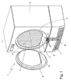
Figure 1 is an isometric view, with parts removed for clarity, of a front-loading rotary-drum home laundry drier realized in accordance with the teachings of the present invention; -
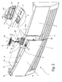
Figure 2 is a partly-exploded isometric view, with parts in section and parts removed for clarity, of the bottom portion of theFigure 1 home laundry drier; -
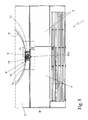
Figure 3 is a front view, with parts in section and parts removed for clarity, of the bottom portion of theFigure 1 home laundry drier; -
Figure 4 is a side view, with parts in section and parts removed for clarity, of the bottom portion of theFigure 1 home laundry drier; and -
Figure 5 is a top view, with parts in section and parts removed for clarity, of the bottom portion of theFigure 1 home laundry drier. - With reference to
Figures 1 ,2 and3 ,number 1 indicates as a whole a household appliance for laundry drying, namely a front-loading rotary-drum home laundry drier, which comprises: a preferably, though not necessarily, parallelepiped-shapedouter box casing 2; a preferably, though not necessarily, cylindrical, bell-shaped revolvingdrum 3 for housing the laundry to be dried, and which is fixed in axially rotating manner insidecasing 2, directly facing a laundry loading/ unloadingopening 2a formed in the front face ofcasing 2; and aporthole door 4 hinged to the front face ofcasing 2 to rotate to and from a closing position in whichporthole door 4 rests againstcasing 2 to close opening 2a and seal the revolvingdrum 3. - More specifically, in the example shown revolving
drum 3 rests horizontally insidecasing 2 and is able to freely rotate about its longitudinal axis L; whereas the laundry loading/unloadingopening 2a is preferably, though not necessarily, substantially circular in shape, and is preferably, though not necessarily, realized on the bottom of a preferably, though not necessarily, substantially circular-shapedrecessed seat 5 formed on the front face ofcasing 2. - The
porthole door 4, in turn, is complementary in shape to therecessed seat 5, i.e. substantially circular-shaped, and is hinged to the front face ofcasing 2, close to the peripheral edge of the laundry loading/unloading opening 2a and preferably, though not necessarily, on the bottom ofrecessed seat 5, so as to freely rotate about a preferably, though not necessarily, vertical reference axis A, to and from the closing position in which the whole peripheral edge of theporthole door 4 rests against the bottom of recessedseat 5 so to airtight seal the laundry loading/unloadingopening 2a. - Preferably, though not necessarily, the
porthole door 4 is also provided with a first manually-operated door-lock device (not shown) which is structured for selectively lock theporthole door 4 to themachine casing 2 when theporthole door 4 is located in the closing position so to selectively prevent the movement ofporthole door 4 away from the closing position. -
Casing 2, revolvingdrum 3 andporthole door 4 are commonly known parts in the industry, and therefore not described in detail. -
Household appliance 1 also comprises a motor assembly for rotating, on command, revolvingdrum 3 about its longitudinal axis L insidecasing 2; and a closed-circuit, hot-air generator which is completely housed insidecasing 2 and is structured to circulate through revolving drum 3 a stream of hot air having a low moisture level, and which flows over and rapidly dries the laundry insidedrum 3. - More specifically, the closed-circuit, hot-air generator provides for gradually drawing moist air from revolving
drum 3; extracting surplus moisture from the hot air drawn from revolvingdrum 3; heating the dehumidified air to a predetermined temperature, normally higher than the temperature of the air from revolvingdrum 3; and feeding the heated, dehumidified air back into revolvingdrum 3, where it flows over, to rapidly dry, the laundry inside the drum. - In other words, the hot-air generator provides for continually dehumidifying and heating the air circulating inside revolving
drum 3 to rapidly dry the laundry inside the latter, and substantially comprises: - an air recirculating conduit (not shown), the two ends of which are connected to revolving
drum 3 preferably, though not necessarily, on opposite sides of the latter; - an electric fan (not shown) or other type of air circulating pump, namely an electric centrifugal fan, which is located along the air recirculating conduit to produce, inside the air recirculating conduit, an airflow which flows through revolving drum and over the laundry inside the
drum 3; - an air/air heat exchanger (not shown) which is located along the air recirculating conduit preferably, thought not necessarily, downstream of the centrifugal fan, and is structured so that the moist airflow arriving from revolving
drum 3 and a cold airflow arriving fromoutside casing 2 can flow through it simultaneously without mixing one another, allowing at the same time the cold airflow arriving from outsidecasing 2 to rapidly cool the moist airflow arriving from revolvingdrum 3 so to cause condensation of the surplus moisture inside the moist airflow; - an electric heater (not shown), namely a resistor, which is located along the air recirculating conduit,
- Preferably, thought not necessarily, the hot-air generator of
household appliance 1 is also provided with a second electric fan (not shown) which is located intocasing 2, next to the air/air heat exchanger, so to produce, on command, the airflow of external cold air which flows through the air/air heat exchanger together with the moist airflow arriving from revolvingdrum 3, and which has a temperature lower than that of the moist airflow arriving from revolvingdrum 3, so to absorb heat from the moist airflow arriving from revolvingdrum 3 and cause the condensation of the surplus moisture inside the latter. - With reference to
Figures 1 and2 , in particular, the air/air heat exchanger (not shown) is housed in stable, but easy removable, manner into aboxlike container 6 which is located insidecasing 2, below revolvingdrum 3 and along the air recirculating conduit, and is accessible from the outside via a second opening 2b formed in the front face ofcasing 2, immediately beneath therecessed seat 5 having at centre the laundry loading/unloadingopening 2a; and thehousehold appliance 1 is provided with asecond door 7 which, likewiseporthole door 4, is hinged to the front face ofcasing 2 to rotate to and from a closing position in whichdoor 7 rests against the front face ofcasing 2 to shut opening 2b and impair the removal of the air/air heat exchanger from theboxlike container 6. - More specifically, in the example shown the heat exchanger is structured for being inserted in drawer-like and airtight manner into the
boxlike container 6, through opening 2b; whereas opening 2b is preferably, though not necessarily, substantially rectangular in shaped, and is realized on the front face ofcasing 2, next to the bottom of the latter. - With reference to
Figures 1 ,2 and3 ,door 7, in turn, is preferably, though not necessarily, substantially flat and rectangular in shape; lies on a reference laying plane P which is locally substantially tangent and parallel to the reference laying plane of the front face ofcasing 2 whendoor 7 rests in the closing position; is dimensioned for completely cover opening 2b when laying on the front face ofcasing 2; and is hinged in flag-type manner to the front face ofcasing 2, close to the peripheral edge of opening 2b, so to freely rotate about a preferably, though not necessarily, vertical reference axis B, to and from the above cited closing position in whichdoor 7 rests against the front face ofcasing 2 to completely cover opening 2b and impair the removal of the exchanger from theboxlike container 6. - With reference to
Figures 1 to 5 ,household appliance 1 finally comprises a second manually-operateddoor lock device 8 which is structured to firmly lockdoor 7 to the front face ofcasing 2 whendoor 7 rests against the front face ofcasing 2 in the closing position, so to selectively prevent the movement ofdoor 7 away from the closing position; and preferably, though not necessarily, also an elastic member (not shown), namely a torsion bar or a spiral spring, which is structured for pushingdoor 7 away from its closing position. - In other words, manually-operated
door lock device 8 impairs the accidental opening ofdoor 7. - With reference to
Figures 2 to 5 , the manually-operated door-lock device 8 is located on the front face ofcasing 2, immediately above opening 2b, and comprises: - a
longitudinal groove 9 extending on the upperlateral side 7a ofdoor 7 locally substantially parallel to the reference laying plane P of thedoor 7, so to be oriented locally substantially parallel to the reference laying plane of the front face ofcasing 2 whendoor 7 is resting on the front face ofcasing 2 in the closing position; - a sliding
element 10 located on the front face ofcasing 2, immediately above opening 2b anddoor 7 resting in the closing position, and which is fitted in sliding manner on the front face ofcasing 2 so to be manually movable on surface ofcasing 2 in a direction d1 which is locally substantially tangent to the surface of the front face ofcasing 2, and locally substantially parallel to thegroove 9 realized on the upperlateral side 7a of thedoor 7 resting on the front face ofcasing 2 in the closing position; and - a
transversal locking member 11 which protrudes from slidingelement 10 towards theunderneath door 7, remaining locally substantially parallel to the reference laying plane of the front face ofcasing 2 and of thedoor 7 in the closing position, so that thedistal end 11a oflocking member 11 can stick out in front of opening 2b, and fits into therecessed groove 9 realized on the upperlateral side 7a ofdoor 7. - More specifically, sliding
element 10 andlocking member 11 are coupled to one another so thattransversal locking member 11 is movable, with respect tocasing 2 and together with slidingelement 10, exclusively on a drifting plane D which is locally substantially parallel to the travelling direction d1 of slidingelement 10 and to the reference laying plane of the front face ofcasing 2, i.e. locally substantially parallel to groove 9 ofdoor 7 whendoor 7 rests on the front face ofcasing 2 in the closing position. - In particular, with reference to
Figures 4 and 5 , in the example shown the drifting plane D oflocking member 11 is preferably, though not necessarily, coincident with the reference laying plane P of thedoor 7 resting in the closing position. - Since displacement of
door 7 away from the closing position - i.e. a rotation ofdoor 7 about axis B - implies thegroove 9 to move, with respect to lockingmember 11, in a travelling direction do locally substantially perpendicular to the drifting plane D of locking member 11 (and of the reference laying plane P of thedoor 7 resting in the closing position), thetransversal locking member 11 is structured to impairdoor 7 from moving away from its closing position when thedistal end 11a of lockingmember 11 engages intogroove 9. More specifically, on opening ofdoor 7, the travelling direction oflocking member 11 with respect togroove 9 is locally substantially perpendicular to the reference lying plane P ofdoor 7, but the lateral banks ofgroove 9 impairs any movement of thedistal end 11a oflocking member 11 in a direction locally perpendicular to the reference lying plane P ofdoor 7. - In addition to the above, with reference to
Figures 2 and5 , a first end ofgroove 9 is located approximately in the middle of the upperlateral side 7a ofdoor 7, so to impair any movement of thedistal end 11a oflocking member 11 out ofgroove 9; and a second end ofgroove 9 communicates with the outside of the upperlateral side 7a ofdoor 7, so to allow the disengagement/coming out of thedistal end 11a oflocking member 11 fromgroove 9. Thustransversal locking member 11 is able to impairdoor 7 from moving away from the closing position only when thedistal end 11a of lockingmember 11 engages intogroove 9, and does not occupy the second end ofgroove 9. - In particular, in the example shown the second end of
groove 9 communicates with the outside of the upper lateral side ofdoor 7 preferably, thought not necessarily, via antransversal channel 13 which comes out of thelateral side 7a ofdoor 7 on the rear face of the latter, which directly faces opening 2b whendoor 7 rests on the front face ofcasing 2 in the closing position. Thetransversal channel 13 is dimensioned for being engaged in sliding manner by thedistal end 11a oflocking member 11 so to allow thedistal end 11a oflocking member 11 to come out of thegroove 9 on the upperlateral side 7a ofdoor 7, and thedoor 7 to freely rotated about axis B for moving away from the closing position. - More specifically, in the example shown the
transversal channel 13 extends on the upperlateral side 7a ofdoor 7 preferably, thought not necessarily, substantially perpendicular to groove 9, i.e. to the reference laying plane P ofdoor 7, so to be locally aligned to the travelling direction do of thegroove 9 whendoor 7 rotates about axis B for moving away from its closing position. - With reference to
Figure 2 , the manually-operated door-lock device 8 preferably, thought not necessarily, also comprises anelastic member 12 which is interposed betweencasing 2 and slidingelement 10, and is structured to push and hold thesliding element 10 and thelocking member 11 in a resting position, in which thedistal end 11a oflocking member 11, ifdoor 7 is resting on the front face ofcasing 2 in the closing position, engagesgroove 9 and is located approximately into the first end of groove 9 (seeFigure 5 ), so thatlocking member 11 can impair thedoor 7 from moving away from the closing position. - With reference to
Figures 1 ,2 and3 , in a preferred embodiment, the upperlateral side 7a ofdoor 7 and thegroove 9 are substantially horizontal, thus thesliding element 10 is movable on the front face ofcasing 2 in a travelling direction d1 which is locally substantially horizontal and tangent to the front face ofcasing 2. - In addition to the above, in this preferred embodiment the
sliding element 10 is preferably, though not necessarily, located on the lateral fall of the circular-shapedrecessed seat 5, immediately above the upperlateral side 7a ofdoor 7, so to be completely covered by theporthole door 4 when fitted into the recessedseat 5 in the closing position. Thus the user can reach and move thesliding element 10 in direction d1 only when theporthole door 4 is completely opened and the internal safety system of thehousehold appliance 1 has completely deactivated thehousehold appliance 1, or at least switched off the motor assembly which rotates the revolvingdrum 3. - The internal safety system is a commonly known part of today's front-loading rotary-drum home laundry driers, and therefore won't be described in detail.
- More specifically, with reference to
Figures 2 ,3 and4 , in the example shown thesliding element 10 is inserted in sliding manner into the elongatedcentral slot 14a of a supportingbase 14 structured for being stably recessed into a specific through opening realized in the substantially cylindrical lateral fall of recessed seat 5 (i.e. the annular frame which surrounds the laundry loading/unloading opening realized on the front face of the casing of a front-loading rotary-drum home laundry drier), and which is vertically aligned to thegroove 9 on the upperlateral side 7a ofdoor 7 whendoor 7 is laying on the front face ofcasing 2 in the closing position. - In the example shown, the cylindrical lateral fall of
recessed seat 5 therefore defines an annular edge adapted to receive the corresponding annular edge of theporthole door 4 so as to properly close loading/unloadingopening 2a. The slidingelement 10 is movable along the annular edge in a direction d1 which is substantially tangent to the profile of the annular edge of therecessed seat 5, so that slidingelement 10 is adapted to slide, under the action of the user, along an horizontal direction path between a first position in which thelocking member 11 engages thefirst door 7 thereby preventing the latter from opening and a second position in which thelocking member 11 releases the first door (7) which is free to open. - It is to be noted that, in response to the displacement of the sliding
member 10, also thelocking member 11 moves/slides along a horizontal direction path between the first and second position above-mentioned. - It is evident that in an alternative embodiment, the edge of the
recessed seat 5 and the corresponding edge of theporthole door 4 can be square-shaped or similar instead of annular-shaped. - With reference to
Figures 2 ,3 and4 ,transversal locking member 11, in turn, comprises a straight locking pin orrod 15 which is fitted in axially sliding manner into the body of slidingelement 10, and extends trough thecentral slot 14a of supportingbase 14 towardsdoor 7, remaining substantially coaxial to a reference axis C which lays on the drifting plane D and is substantially perpendicular to the travelling direction d1 of thesliding element 10 oncasing 2; and anelastic element 16 which is structured for springy holding the locking pin orrod 15 in an extracted position, in which the distal end of locking pin orrod 14 sticks out from supportingbase 14 and fromcasing 2, just ahead opening 2b, and can fit into thelongitudinal groove 9 realized on the upperlateral side 7a ofdoor 7. - More specifically, locking pin or
rod 15 is freely movable, with respect to the body of slidingelement 10, back and forth towards the upperlateral side 7a of thedoor 7 resting on the front face ofcasing 2; and theelastic element 16, namely a coil spring, is interposed between the locking pin orrod 15 and the slidingelement 10, and is structured for axially pushing the locking pin orrod 11 downward, towards the upperlateral side 7a ofdoor 7, so to hold the locking pin orrod 15 in an extracted position, in which the distal end of locking pin orrod 15, corresponding todistal end 11a of transversal lockingmember 11, sticks out from supportingbase 15 and fromcasing 2, just in front ofopening 2b, and fits into thelongitudinal groove 9 ondoor 7. - In the example shown, in particular, axis C lies on drifting plane D, is preferably, though non necessarily, parallel to rotation axis B and is vertically oriented.
- Moreover, with reference to
Figure 4 , thedistal end 11a of locking pin orrod 15 is preferably, though non necessarily, shaped so to have a flat sloping profile which forces the whole locking pin orrod 15 to move upwards, i.e. away from the extracted position, when thedistal end 11a of locking pin orrod 15 comes in abutment against the lateral edge ofdoor 7 defining the border between the rear face ofdoor 7 and the upperlateral side 7a ofdoor 7. - In addition to the above, with reference to
Figures 2 and5 , to improve the lifting action of thedistal end 11a of locking pin orrod 15, aramp 17 which is tilted towards the rear face ofdoor 7, is realized on the upperlateral side 7a ofdoor 7, close to the first end ofgroove 9, so to ease the jump of thedistal end 11a of locking pin orrod 15 directly into the first end ofgroove 9 while slidingelement 10 remains in the resting position together with the wholetransversal locking member 11. - General operation of
household appliance 1 for laundry drying is clearly inferable from the above description, with no further explanation required. - The advantages connected to the particular structure of manually-operated door-
lock device 8 are considerable and large in number. First of all, manually-operated door-lock device 8 is much more compact than that used in today's front-loading rotary-drum home laundry driers, allowing the housing of the manually-operated door-lock device 8 also inside the annular frame surrounding the laundry loading/unloading opening of a casing having a very huge laundry loading/unloading opening. - Moreover the manually-operated door-
lock device 8 does not require a latchlock assembly attached to the rear face ofdoor 7, thus allowing a significant reduction of the overall thickness ofdoor 7. - Finally, the manually-operated door-
lock device 8 has a simplified structure which renders the manually-operated door-lock device 8 less expensive to produce than the manually-operated door-lock device of today's front-loading rotary-drum home laundry driers. - Clearly, changes may be made to
household appliance 1 and/or manually-operated door-lock device 8 as described herein without, however, departing from the scope of the present invention. - For example, the
longitudinal groove 9 may be replaced by a longitudinal projecting rib extending on the upperlateral side 7a ofdoor 7 so to be locally substantially parallel to the reference laying plane P ofdoor 7. In which case, thedistal end 11a of lockingmember 11 engages the longitudinal projecting rib, and the movement of thedistal end 11a of lockingmember 11, onto the upperlateral side 7a ofdoor 7 and in a direction locally perpendicular to the reference lying plane P ofdoor 7, is impaired by the lateral bank of the longitudinal projecting rib to which thedistal end 11a of lockingmember 11 abuts whendoor 7 rests on the front face ofcasing 2 in the closing position. - Furthermore, according to a second embodiment, the manually-operated door-
lock device 8 may be located next to the vertical edge ofdoor 7, opposite to the door hinge. In which case,groove 9 extends on the vertical lateral side ofdoor 7 locally substantially parallel to the reference laying plane P of thedoor 7, while remaining always substantially parallel to the reference laying plane of the front face ofcasing 2 whendoor 7 is resting on the front face ofcasing 2 in the closing position. The slidingelement 10 is located on the front face ofcasing 2, immediately sideways ofopening 2b, so to facegroove 9, and is fitted in sliding manner on the front face ofcasing 2 so to be manually movable on surface ofcasing 2 in a vertical direction. - According to a third embodiment,
porthole door 4 and recessedseat 5 may be substantially rectangular in shape. - Moreover according to a first variation of the door-
lock device 8, thetransversal channel 13 connecting the second end ofgroove 9 to the rear face ofboor 7 could have a flat bottom surface tilted towards the rear face ofdoor 7, so that the locking pin orrod 15, when having adistal end 11a with a flat sloping profile, would push the upperlateral side 7a ofdoor 7 away from the front face ofcasing 2, when thedistal end 11a of locking pin orrod 15 arrives in the second end ofgroove 9 and enters intransversal channel 13. - In which case, the optional elastic member structured for pushing
door 7 away from its closing position is no more necessary and its function is performed by theelastic element 16 of transversal lockingmember 11. - Finally according to a simplified variation of the door-
lock device 8,elastic element 16 is missing and the straight locking pin orrod 15 is rigidly fixed to the body of slidingelement 10.
Claims (15)
- Household appliance (1) comprising an outer box casing (3) which is provided with a first opening (2b) in its front face, a first door (7) which is hinged to the front face of the casing (2) to rotate to and from a closing position in which said first door (7) rests against the front face of the casing (2) to close said first opening (2b), and a manually-operated door lock device (8) which is structured to selectively lock the first door (7) to the front face of the casing (2) when the first door (7) is placed in the closing position; the household appliance (1) being characterized in that said manually-operated door lock device (8) comprises:- a longitudinal groove (9) extending on a lateral side (7a) of the first door (7) so to be locally substantially parallel to the reference laying plane (P) of the door (7), and to be locally substantially parallel to the reference laying plane of the front face of the casing (2) when the first door (7) is resting in the closing position;- a sliding element (10) located on the front face of the casing (2), immediately sideways of the first opening (2b), and which is fitted in sliding manner on the front face of the casing (2) so to be manually movable on the casing (2) in a direction (d1) which is locally substantially tangent to the front face of the casing (2), and locally substantially parallel to the groove (9) realized on the lateral side (7a) of the first door (7); and- a transversal locking member (11) which protrudes from the sliding element (10) towards the first door (7) remaining locally substantially parallel to the reference laying plane of the front face of the casing (2), so that the distal end (11a) of said locking member (11) can fit into the groove (9) realized on the lateral side (7a) of the first door (7) ;the transversal locking member (11) being structured to impair the first door (7) from moving away from the closing position when the distal end (11a) of the locking member (11) engages into the groove (9).
- A household appliance according to Claim 1, characterized in that the sliding element (10) and the transversal locking member (11) are coupled to one another so that the locking member (11) is movable, with respect to the casing (2) and together with the sliding element (10), on a drifting plane (D) which is locally substantially parallel to the groove (9) and to the reference laying plane of the front face of the casing (2).
- A household appliance according to Claim 2, characterized in that a first end of the groove (9) is located approximately in the middle of the lateral side (7a) of the first door (7), so to impair any movement of the distal end (11a) of the locking member (11) out of the groove (9); and that a second end of the groove (9) communicates with the outside of the lateral side (7a) of the first door (7), so to allow the disengagement/coming out of the distal end (11a) of the locking member (11) from the groove (9); the transversal locking member (11) being able to impair the first door (7) from moving away from the closing position only when the distal end (11a) of the locking member (11) engages into the groove (9), and does not occupy the second end of the groove (9).
- A household appliance according to Claim 3, characterized in that the second end of the groove (9) communicates with the outside of the door lateral side (7a) via an transversal channel (13) which comes out of the door lateral side (7a) on the rear face of the first door (7), which directly faces the first opening (2b) when the first door (7) rests on the front face of casing (2) in the closing position; the transversal channel (13) being dimensioned for being engaged in sliding manner by the distal end (11a) of the locking member (11).
- A household appliance according to Claim 3 or 4, characterized in that the said manually-operated door lock device (8) also comprises elastic means (12) which are structured so to push and hold the sliding element (10) and the transversal locking member (11) in a resting position, in which the distal end (11a) of the locking member (11), when the first door (7) is resting in the closing position, engages the groove (9) and is located approximately into the first end of groove (9), so that the locking member (11) can impair the first door (7) from moving away from the closing position.
- A household appliance according to any one of the preceding claims, characterized in that the transversal locking member (11) comprises a straight locking pin (15) which extends from the body of the sliding element (10) and towards the first door (7), remaining substantially coaxial to a first axis (C) which substantially lays on the drifting plane (D) and is substantially perpendicular to the travelling direction (d1) of the sliding element (10) on the casing (2).
- A household appliance according to claims 6, characterized in that the straight locking pin (15) is fitted in axially sliding manner into the body of the sliding element (10), so to move back and forth towards the lateral side 7a of the first door 7 when resting on the front face of the casing 2; the said manually-operated door lock device (8) also comprising an elastic element (16) which is structured for springy holding the locking pin (15) in an extracted position, in which the distal end (11a) of the locking pin (14) can fit into the groove (9) realized on the lateral side (7a) of the first door (7).
- A household appliance according to any of the preceding claims, characterized in that the sliding element (10) is inserted in sliding manner into the elongated central slot (14a) of a supporting base (14) structured for being stably recessed into a specific through opening realized in the front face of the casing (2); the transversal locking member (11) extending trough the central slot (14a) of the supporting base (14) towards the first door (7).
- A household appliance according to any of the preceding claims, characterized by also comprising, inside the casing (2),- a substantially bell-shaped revolving drum (3) for housing the laundry to be dried, and which is fixed in axially rotating manner inside the casing (2), directly facing a laundry loading/unloading opening (2a) formed in the front face of the casing (2); and- a second door (4) hinged to the front face of the casing (2) to rotate to and from a closing position in which the second door (5) rests completely against the casing (2) to close the laundry loading/unloading opening (2a) and seal the revolving drum (3);the laundry loading/unloading opening (2a) being realized on the front face of the casing (2), sideways of the first opening (2a).
- A household appliance according to Claim 9, characterized in that the laundry loading/unloading opening (2a) is realized on the front face of the casing (2) above the first opening (2a).
- A household appliance according to Claim 10, characterized in that the first door (7) and the second door (4) are hinged to the front face of the casing (2), so to freely rotate about a respective reference axis (A; B) substantially vertically oriented.
- A household appliance according to Claim 9 or 11, characterized in that the laundry loading/unloading opening (2a) is realized on the bottom of a recessed seat (5) formed on the front face of the casing (2), and the sliding element (10) is located on the lateral fall of the recessed seat (5), immediately above the lateral side (7a) of the first door (7).
- A household appliance according to Claim 12, characterized in that the second door (4) is complementary in shape to the recessed seat (5), and is hinged to the front face of the casing (2), close to the peripheral edge of the laundry loading/unloading opening (2a), so to freely rotate about a reference axis (A) to and from a closing position in which the whole peripheral edge of the second door (4) rests against the bottom of the recessed seat (5) so to close the laundry loading/unloading opening (2a); the sliding element (10) being completely covered by the second door (4) when the second door (4) is fitted into the recessed seat (5) in the closing position.
- A household appliance according to any one of Claims 9 to 13, characterized by comprising a closed-circuit, hot-air generator which is housed inside the casing (2) and is structured to circulate through revolving drum (3) a stream of hot air having a low moisture level, and which flows over and rapidly dries the laundry inside drum (3).
- A household appliance according to Claim 13, characterized in that said closed-circuit, hot-air generator comprises a removable heat exchanger which is housed in a stable, but easy removable, manner into a container (6) located inside casing (2), and which is accessible from the outside via the first opening (2b) formed in the front face of casing (2); when resting on front face of the casing (2) in the closing position, the first door (7) being able to impair the removal of the heat exchanger from the container (6).
Priority Applications (2)
| Application Number | Priority Date | Filing Date | Title |
|---|---|---|---|
| PL09009216T PL2278057T3 (en) | 2009-07-15 | 2009-07-15 | Household appliance for laundry drying |
| EP09009216.4A EP2278057B1 (en) | 2009-07-15 | 2009-07-15 | Household appliance for laundry drying |
Applications Claiming Priority (1)
| Application Number | Priority Date | Filing Date | Title |
|---|---|---|---|
| EP09009216.4A EP2278057B1 (en) | 2009-07-15 | 2009-07-15 | Household appliance for laundry drying |
Publications (2)
| Publication Number | Publication Date |
|---|---|
| EP2278057A1 true EP2278057A1 (en) | 2011-01-26 |
| EP2278057B1 EP2278057B1 (en) | 2016-10-26 |
Family
ID=41210798
Family Applications (1)
| Application Number | Title | Priority Date | Filing Date |
|---|---|---|---|
| EP09009216.4A Not-in-force EP2278057B1 (en) | 2009-07-15 | 2009-07-15 | Household appliance for laundry drying |
Country Status (2)
| Country | Link |
|---|---|
| EP (1) | EP2278057B1 (en) |
| PL (1) | PL2278057T3 (en) |
Cited By (1)
| Publication number | Priority date | Publication date | Assignee | Title |
|---|---|---|---|---|
| JP2015054003A (en) * | 2013-09-11 | 2015-03-23 | パナソニックIpマネジメント株式会社 | Drum washing machine |
Citations (3)
| Publication number | Priority date | Publication date | Assignee | Title |
|---|---|---|---|---|
| GB1117044A (en) * | 1966-03-16 | 1968-06-12 | Ft Products Ltd | An improved socket for a releasable catch |
| US4510776A (en) * | 1983-12-27 | 1985-04-16 | The Maytag Company | Sliding access door for washing machine |
| EP1972714A1 (en) * | 2007-03-19 | 2008-09-24 | BITRON S.p.A. | A door-locking device with emergency release, particularly for domestic appliances |
-
2009
- 2009-07-15 EP EP09009216.4A patent/EP2278057B1/en not_active Not-in-force
- 2009-07-15 PL PL09009216T patent/PL2278057T3/en unknown
Patent Citations (3)
| Publication number | Priority date | Publication date | Assignee | Title |
|---|---|---|---|---|
| GB1117044A (en) * | 1966-03-16 | 1968-06-12 | Ft Products Ltd | An improved socket for a releasable catch |
| US4510776A (en) * | 1983-12-27 | 1985-04-16 | The Maytag Company | Sliding access door for washing machine |
| EP1972714A1 (en) * | 2007-03-19 | 2008-09-24 | BITRON S.p.A. | A door-locking device with emergency release, particularly for domestic appliances |
Cited By (1)
| Publication number | Priority date | Publication date | Assignee | Title |
|---|---|---|---|---|
| JP2015054003A (en) * | 2013-09-11 | 2015-03-23 | パナソニックIpマネジメント株式会社 | Drum washing machine |
Also Published As
| Publication number | Publication date |
|---|---|
| PL2278057T3 (en) | 2017-06-30 |
| EP2278057B1 (en) | 2016-10-26 |
Similar Documents
| Publication | Publication Date | Title |
|---|---|---|
| EP2870283B1 (en) | Laundry dryer | |
| EP2870284B1 (en) | Laundry dryer | |
| EP2867401B1 (en) | Laundry dryer | |
| EP3309291B1 (en) | Clothes dryer | |
| AU2012265068B2 (en) | Rotary-drum laundry dryer | |
| US20130145648A1 (en) | Filter guide having latch device of filter cover and clothes-drying machine using the same | |
| US11154910B2 (en) | Laundry dryer comprising a filter assembly and a method to clean a filter assembly | |
| KR20150009326A (en) | Laundry drying Apparatus | |
| AU2011335159B2 (en) | Laundry dryer | |
| JP6660079B2 (en) | Washing and drying machine | |
| EP2843114A1 (en) | Rotary-drum laundry dryer | |
| EP2708638A1 (en) | Rotary-drum laundry dryer | |
| EP2527523B1 (en) | Rotary-drum laundry dryer | |
| EP2278057B1 (en) | Household appliance for laundry drying | |
| EP2843112B1 (en) | Rotary-drum laundry dryer | |
| KR102284362B1 (en) | Laundry drying Apparatus | |
| CN110114529B (en) | Laundry dryer including filter assembly and method of cleaning filter assembly | |
| KR100641418B1 (en) | Temperature sensor mounting structure of clothes dryer | |
| EP2527524A1 (en) | Rotary-drum laundry dryer | |
| JP2024003277A (en) | clothing processing equipment | |
| KR101246375B1 (en) | Dryer having lack for holding footwear | |
| EP3124683A1 (en) | Laundry dryer | |
| KR101527021B1 (en) | Dryer | |
| KR20080040384A (en) | Dryer with slip resistant belt |
Legal Events
| Date | Code | Title | Description |
|---|---|---|---|
| PUAI | Public reference made under article 153(3) epc to a published international application that has entered the european phase |
Free format text: ORIGINAL CODE: 0009012 |
|
| AK | Designated contracting states |
Kind code of ref document: A1 Designated state(s): AT BE BG CH CY CZ DE DK EE ES FI FR GB GR HR HU IE IS IT LI LT LU LV MC MK MT NL NO PL PT RO SE SI SK SM TR |
|
| AX | Request for extension of the european patent |
Extension state: AL BA RS |
|
| RAP1 | Party data changed (applicant data changed or rights of an application transferred) |
Owner name: ELECTROLUX HOME PRODUCTS CORPORATION N.V. |
|
| RAP1 | Party data changed (applicant data changed or rights of an application transferred) |
Owner name: ELECTROLUX HOME PRODUCTS CORPORATION N.V. |
|
| 17P | Request for examination filed |
Effective date: 20110726 |
|
| 17Q | First examination report despatched |
Effective date: 20110811 |
|
| GRAP | Despatch of communication of intention to grant a patent |
Free format text: ORIGINAL CODE: EPIDOSNIGR1 |
|
| INTG | Intention to grant announced |
Effective date: 20160426 |
|
| GRAS | Grant fee paid |
Free format text: ORIGINAL CODE: EPIDOSNIGR3 |
|
| GRAA | (expected) grant |
Free format text: ORIGINAL CODE: 0009210 |
|
| AK | Designated contracting states |
Kind code of ref document: B1 Designated state(s): AT BE BG CH CY CZ DE DK EE ES FI FR GB GR HR HU IE IS IT LI LT LU LV MC MK MT NL NO PL PT RO SE SI SK SM TR |
|
| REG | Reference to a national code |
Ref country code: GB Ref legal event code: FG4D |
|
| REG | Reference to a national code |
Ref country code: CH Ref legal event code: EP |
|
| REG | Reference to a national code |
Ref country code: AT Ref legal event code: REF Ref document number: 840120 Country of ref document: AT Kind code of ref document: T Effective date: 20161115 |
|
| REG | Reference to a national code |
Ref country code: IE Ref legal event code: FG4D |
|
| REG | Reference to a national code |
Ref country code: DE Ref legal event code: R096 Ref document number: 602009041907 Country of ref document: DE |
|
| REG | Reference to a national code |
Ref country code: LT Ref legal event code: MG4D |
|
| PG25 | Lapsed in a contracting state [announced via postgrant information from national office to epo] |
Ref country code: LV Free format text: LAPSE BECAUSE OF FAILURE TO SUBMIT A TRANSLATION OF THE DESCRIPTION OR TO PAY THE FEE WITHIN THE PRESCRIBED TIME-LIMIT Effective date: 20161026 |
|
| REG | Reference to a national code |
Ref country code: NL Ref legal event code: MP Effective date: 20161026 |
|
| REG | Reference to a national code |
Ref country code: AT Ref legal event code: MK05 Ref document number: 840120 Country of ref document: AT Kind code of ref document: T Effective date: 20161026 |
|
| PG25 | Lapsed in a contracting state [announced via postgrant information from national office to epo] |
Ref country code: LT Free format text: LAPSE BECAUSE OF FAILURE TO SUBMIT A TRANSLATION OF THE DESCRIPTION OR TO PAY THE FEE WITHIN THE PRESCRIBED TIME-LIMIT Effective date: 20161026 Ref country code: NO Free format text: LAPSE BECAUSE OF FAILURE TO SUBMIT A TRANSLATION OF THE DESCRIPTION OR TO PAY THE FEE WITHIN THE PRESCRIBED TIME-LIMIT Effective date: 20170126 Ref country code: SE Free format text: LAPSE BECAUSE OF FAILURE TO SUBMIT A TRANSLATION OF THE DESCRIPTION OR TO PAY THE FEE WITHIN THE PRESCRIBED TIME-LIMIT Effective date: 20161026 Ref country code: GR Free format text: LAPSE BECAUSE OF FAILURE TO SUBMIT A TRANSLATION OF THE DESCRIPTION OR TO PAY THE FEE WITHIN THE PRESCRIBED TIME-LIMIT Effective date: 20170127 |
|
| PG25 | Lapsed in a contracting state [announced via postgrant information from national office to epo] |
Ref country code: IS Free format text: LAPSE BECAUSE OF FAILURE TO SUBMIT A TRANSLATION OF THE DESCRIPTION OR TO PAY THE FEE WITHIN THE PRESCRIBED TIME-LIMIT Effective date: 20170226 Ref country code: ES Free format text: LAPSE BECAUSE OF FAILURE TO SUBMIT A TRANSLATION OF THE DESCRIPTION OR TO PAY THE FEE WITHIN THE PRESCRIBED TIME-LIMIT Effective date: 20161026 Ref country code: BE Free format text: LAPSE BECAUSE OF FAILURE TO SUBMIT A TRANSLATION OF THE DESCRIPTION OR TO PAY THE FEE WITHIN THE PRESCRIBED TIME-LIMIT Effective date: 20161026 Ref country code: HR Free format text: LAPSE BECAUSE OF FAILURE TO SUBMIT A TRANSLATION OF THE DESCRIPTION OR TO PAY THE FEE WITHIN THE PRESCRIBED TIME-LIMIT Effective date: 20161026 Ref country code: FI Free format text: LAPSE BECAUSE OF FAILURE TO SUBMIT A TRANSLATION OF THE DESCRIPTION OR TO PAY THE FEE WITHIN THE PRESCRIBED TIME-LIMIT Effective date: 20161026 Ref country code: PT Free format text: LAPSE BECAUSE OF FAILURE TO SUBMIT A TRANSLATION OF THE DESCRIPTION OR TO PAY THE FEE WITHIN THE PRESCRIBED TIME-LIMIT Effective date: 20170227 Ref country code: AT Free format text: LAPSE BECAUSE OF FAILURE TO SUBMIT A TRANSLATION OF THE DESCRIPTION OR TO PAY THE FEE WITHIN THE PRESCRIBED TIME-LIMIT Effective date: 20161026 Ref country code: NL Free format text: LAPSE BECAUSE OF FAILURE TO SUBMIT A TRANSLATION OF THE DESCRIPTION OR TO PAY THE FEE WITHIN THE PRESCRIBED TIME-LIMIT Effective date: 20161026 |
|
| REG | Reference to a national code |
Ref country code: DE Ref legal event code: R097 Ref document number: 602009041907 Country of ref document: DE |
|
| PG25 | Lapsed in a contracting state [announced via postgrant information from national office to epo] |
Ref country code: SK Free format text: LAPSE BECAUSE OF FAILURE TO SUBMIT A TRANSLATION OF THE DESCRIPTION OR TO PAY THE FEE WITHIN THE PRESCRIBED TIME-LIMIT Effective date: 20161026 Ref country code: EE Free format text: LAPSE BECAUSE OF FAILURE TO SUBMIT A TRANSLATION OF THE DESCRIPTION OR TO PAY THE FEE WITHIN THE PRESCRIBED TIME-LIMIT Effective date: 20161026 Ref country code: CZ Free format text: LAPSE BECAUSE OF FAILURE TO SUBMIT A TRANSLATION OF THE DESCRIPTION OR TO PAY THE FEE WITHIN THE PRESCRIBED TIME-LIMIT Effective date: 20161026 Ref country code: DK Free format text: LAPSE BECAUSE OF FAILURE TO SUBMIT A TRANSLATION OF THE DESCRIPTION OR TO PAY THE FEE WITHIN THE PRESCRIBED TIME-LIMIT Effective date: 20161026 Ref country code: RO Free format text: LAPSE BECAUSE OF FAILURE TO SUBMIT A TRANSLATION OF THE DESCRIPTION OR TO PAY THE FEE WITHIN THE PRESCRIBED TIME-LIMIT Effective date: 20161026 |
|
| PG25 | Lapsed in a contracting state [announced via postgrant information from national office to epo] |
Ref country code: BG Free format text: LAPSE BECAUSE OF FAILURE TO SUBMIT A TRANSLATION OF THE DESCRIPTION OR TO PAY THE FEE WITHIN THE PRESCRIBED TIME-LIMIT Effective date: 20170126 Ref country code: SM Free format text: LAPSE BECAUSE OF FAILURE TO SUBMIT A TRANSLATION OF THE DESCRIPTION OR TO PAY THE FEE WITHIN THE PRESCRIBED TIME-LIMIT Effective date: 20161026 |
|
| PLBE | No opposition filed within time limit |
Free format text: ORIGINAL CODE: 0009261 |
|
| STAA | Information on the status of an ep patent application or granted ep patent |
Free format text: STATUS: NO OPPOSITION FILED WITHIN TIME LIMIT |
|
| 26N | No opposition filed |
Effective date: 20170727 |
|
| PG25 | Lapsed in a contracting state [announced via postgrant information from national office to epo] |
Ref country code: SI Free format text: LAPSE BECAUSE OF FAILURE TO SUBMIT A TRANSLATION OF THE DESCRIPTION OR TO PAY THE FEE WITHIN THE PRESCRIBED TIME-LIMIT Effective date: 20161026 |
|
| REG | Reference to a national code |
Ref country code: CH Ref legal event code: PL |
|
| GBPC | Gb: european patent ceased through non-payment of renewal fee |
Effective date: 20170715 |
|
| REG | Reference to a national code |
Ref country code: IE Ref legal event code: MM4A |
|
| REG | Reference to a national code |
Ref country code: FR Ref legal event code: ST Effective date: 20180330 |
|
| PG25 | Lapsed in a contracting state [announced via postgrant information from national office to epo] |
Ref country code: LI Free format text: LAPSE BECAUSE OF NON-PAYMENT OF DUE FEES Effective date: 20170731 Ref country code: CH Free format text: LAPSE BECAUSE OF NON-PAYMENT OF DUE FEES Effective date: 20170731 Ref country code: GB Free format text: LAPSE BECAUSE OF NON-PAYMENT OF DUE FEES Effective date: 20170715 Ref country code: IE Free format text: LAPSE BECAUSE OF NON-PAYMENT OF DUE FEES Effective date: 20170715 |
|
| PG25 | Lapsed in a contracting state [announced via postgrant information from national office to epo] |
Ref country code: FR Free format text: LAPSE BECAUSE OF NON-PAYMENT OF DUE FEES Effective date: 20170731 |
|
| PG25 | Lapsed in a contracting state [announced via postgrant information from national office to epo] |
Ref country code: LU Free format text: LAPSE BECAUSE OF NON-PAYMENT OF DUE FEES Effective date: 20170715 |
|
| PG25 | Lapsed in a contracting state [announced via postgrant information from national office to epo] |
Ref country code: MT Free format text: LAPSE BECAUSE OF NON-PAYMENT OF DUE FEES Effective date: 20170715 |
|
| PG25 | Lapsed in a contracting state [announced via postgrant information from national office to epo] |
Ref country code: MC Free format text: LAPSE BECAUSE OF FAILURE TO SUBMIT A TRANSLATION OF THE DESCRIPTION OR TO PAY THE FEE WITHIN THE PRESCRIBED TIME-LIMIT Effective date: 20161026 Ref country code: HU Free format text: LAPSE BECAUSE OF FAILURE TO SUBMIT A TRANSLATION OF THE DESCRIPTION OR TO PAY THE FEE WITHIN THE PRESCRIBED TIME-LIMIT; INVALID AB INITIO Effective date: 20090715 |
|
| PG25 | Lapsed in a contracting state [announced via postgrant information from national office to epo] |
Ref country code: CY Free format text: LAPSE BECAUSE OF NON-PAYMENT OF DUE FEES Effective date: 20161026 |
|
| PG25 | Lapsed in a contracting state [announced via postgrant information from national office to epo] |
Ref country code: MK Free format text: LAPSE BECAUSE OF FAILURE TO SUBMIT A TRANSLATION OF THE DESCRIPTION OR TO PAY THE FEE WITHIN THE PRESCRIBED TIME-LIMIT Effective date: 20161026 |
|
| PG25 | Lapsed in a contracting state [announced via postgrant information from national office to epo] |
Ref country code: TR Free format text: LAPSE BECAUSE OF FAILURE TO SUBMIT A TRANSLATION OF THE DESCRIPTION OR TO PAY THE FEE WITHIN THE PRESCRIBED TIME-LIMIT Effective date: 20161026 |
|
| PGFP | Annual fee paid to national office [announced via postgrant information from national office to epo] |
Ref country code: IT Payment date: 20220726 Year of fee payment: 14 Ref country code: DE Payment date: 20220720 Year of fee payment: 14 |
|
| PGFP | Annual fee paid to national office [announced via postgrant information from national office to epo] |
Ref country code: PL Payment date: 20220711 Year of fee payment: 14 |
|
| P01 | Opt-out of the competence of the unified patent court (upc) registered |
Effective date: 20230625 |
|
| REG | Reference to a national code |
Ref country code: DE Ref legal event code: R119 Ref document number: 602009041907 Country of ref document: DE |
|
| PG25 | Lapsed in a contracting state [announced via postgrant information from national office to epo] |
Ref country code: DE Free format text: LAPSE BECAUSE OF NON-PAYMENT OF DUE FEES Effective date: 20240201 |
|
| PG25 | Lapsed in a contracting state [announced via postgrant information from national office to epo] |
Ref country code: IT Free format text: LAPSE BECAUSE OF NON-PAYMENT OF DUE FEES Effective date: 20230715 |
|
| PG25 | Lapsed in a contracting state [announced via postgrant information from national office to epo] |
Ref country code: PL Free format text: LAPSE BECAUSE OF NON-PAYMENT OF DUE FEES Effective date: 20230715 |
|
| PG25 | Lapsed in a contracting state [announced via postgrant information from national office to epo] |
Ref country code: PL Free format text: LAPSE BECAUSE OF NON-PAYMENT OF DUE FEES Effective date: 20230715 |