EP2277718A1 - Pneumatic tire - Google Patents
Pneumatic tire Download PDFInfo
- Publication number
- EP2277718A1 EP2277718A1 EP09738829A EP09738829A EP2277718A1 EP 2277718 A1 EP2277718 A1 EP 2277718A1 EP 09738829 A EP09738829 A EP 09738829A EP 09738829 A EP09738829 A EP 09738829A EP 2277718 A1 EP2277718 A1 EP 2277718A1
- Authority
- EP
- European Patent Office
- Prior art keywords
- tire
- radial
- protrusion
- width
- protrusions
- Prior art date
- Legal status (The legal status is an assumption and is not a legal conclusion. Google has not performed a legal analysis and makes no representation as to the accuracy of the status listed.)
- Granted
Links
Images


Classifications
-
- B—PERFORMING OPERATIONS; TRANSPORTING
- B60—VEHICLES IN GENERAL
- B60C—VEHICLE TYRES; TYRE INFLATION; TYRE CHANGING; CONNECTING VALVES TO INFLATABLE ELASTIC BODIES IN GENERAL; DEVICES OR ARRANGEMENTS RELATED TO TYRES
- B60C13/00—Tyre sidewalls; Protecting, decorating, marking, or the like, thereof
- B60C13/02—Arrangement of grooves or ribs
-
- B—PERFORMING OPERATIONS; TRANSPORTING
- B60—VEHICLES IN GENERAL
- B60C—VEHICLE TYRES; TYRE INFLATION; TYRE CHANGING; CONNECTING VALVES TO INFLATABLE ELASTIC BODIES IN GENERAL; DEVICES OR ARRANGEMENTS RELATED TO TYRES
- B60C15/00—Tyre beads, e.g. ply turn-up or overlap
- B60C15/02—Seating or securing beads on rims
- B60C15/024—Bead contour, e.g. lips, grooves, or ribs
- B60C15/0242—Bead contour, e.g. lips, grooves, or ribs with bead extensions located radially outside the rim flange position, e.g. rim flange protectors
-
- B—PERFORMING OPERATIONS; TRANSPORTING
- B60—VEHICLES IN GENERAL
- B60C—VEHICLE TYRES; TYRE INFLATION; TYRE CHANGING; CONNECTING VALVES TO INFLATABLE ELASTIC BODIES IN GENERAL; DEVICES OR ARRANGEMENTS RELATED TO TYRES
- B60C17/00—Tyres characterised by means enabling restricted operation in damaged or deflated condition; Accessories therefor
- B60C17/0009—Tyres characterised by means enabling restricted operation in damaged or deflated condition; Accessories therefor comprising sidewall rubber inserts, e.g. crescent shaped inserts
-
- B—PERFORMING OPERATIONS; TRANSPORTING
- B60—VEHICLES IN GENERAL
- B60C—VEHICLE TYRES; TYRE INFLATION; TYRE CHANGING; CONNECTING VALVES TO INFLATABLE ELASTIC BODIES IN GENERAL; DEVICES OR ARRANGEMENTS RELATED TO TYRES
- B60C3/00—Tyres characterised by the transverse section
- B60C3/04—Tyres characterised by the transverse section characterised by the relative dimensions of the section, e.g. low profile
Definitions
- the present invention relates to a pneumatic tire provided with multiple radial protrusions extending in a tire radial direction on a tire surface thereof.
- a rise in the temperature of a pneumatic tire promotes a time-dependent change in a material constituting the pneumatic tire.
- An example of the time-dependent change in the material is a change in properties.
- the temperature rise in the pneumatic tire can also cause damage in a tread portion at high-speed driving. For those reasons, the temperature rise in the pneumatic tire is not desirable in terms of the durability of the pneumatic tire.
- An improvement in the durability is important particularly for an off-the-road radial tire (ORR) and a truck and bus radial tire (TBR) that receive a heavy load, as well as a run-flat tire running flat (running with a tire internal pressure of 0 kPa). Accordingly, it is important for these pneumatic tires to have a reduced temperature rise.
- ORR off-the-road radial tire
- TBR truck and bus radial tire
- the run-flat tire is provided with sidewall reinforcing layers for reinforcing tire side portions.
- the sidewall reinforcing layers each have a crescent shape in a cross section taken in a tire width direction.
- deformation in a tire radial direction concentrates on the sidewall reinforcing layers.
- the sidewall reinforcing layers have an increased temperature, consequently deteriorating the durability of the run-flat tire.
- Patent Literature 1 Japanese Patent Application Publication No. 2006-76431
- a load applied to the pneumatic tire might lead to a separation of the reinforcing members.
- the reinforcing member might be a factor for other damage.
- the reinforcing members provided to the tire side portions improve the rigidity of the tire side portions, and therefore make the pneumatic tire more bouncy. This consequently might degrade the steering stability, ride quality, and the like.
- the run-flat tire in particular, has high rigidity in the tire side portions; therefore, the ride quality and the like might be degraded.
- the intention of the second technique described above is to improve the radiation performance by increasing the surface area of the pneumatic tire.
- the outer surface of the pneumatic tire is preferably made of a rubber material having low heat conductivity such as to prevent conduction of friction heat generated between the pneumatic tire and the road surface. Accordingly, the temperature rise in the tire side portions cannot be sufficiently suppressed by simply increasing the surface area of the pneumatic tire.
- the present invention has been made to solve the above problems, and has an objective of providing a pneumatic tire capable of sufficiently suppressing the temperature rise in the tire side portions.
- the first aspect of the present invention is summarized as a pneumatic tire comprising a plurality of radial protrusions (radial protrusions 60) each extending in a tire radial direction on a tire surface (tire surface 31) and having a shape protruding from the tire surface outward in a tire width direction, wherein the plurality of radial protrusions are provided radially with a tire rotation axis as a center, the plurality of radial protrusions each have an outer end portion (outer end portion 62) being an end portion located on an outer side in the tire radial direction, and the outer end portion is provided to the tire surface in a tire maximum width portion (maximum width portion T) in the tire width direction.
- the pneumatic tire has the multiple radial protrusions protruding from the tire surface outward in the tire width direction. Accordingly, airflow flowing on the tire side portion (the tire surface) crosses over the radial protrusion. Then, the airflow flows toward the tire surface in the direction substantially perpendicular thereto at a position behind the radial protrusion in the tire rotation direction, and then collides heavily with the tire surface. Consequently, the airflow and the tire surface actively exchange heat with each other, sufficiently suppressing the temperature rise in the tire side portion (tire surface). This, as a result, improves the durability of the tire.
- the outer end portions of the radial protrusions are provided outside the maximum width portion in the tire radial direction.
- the radial protrusions come in contact with the road surface.
- the radial protrusions suffer from friction heat, increasing the temperature in the tire side portion.
- friction between the radial protrusions and the road surface might chip or remove the radial protrusions. This consequently lowers the visibility for the pneumatic tire.
- the outer end portions are provided in the maximum width portion. Accordingly, even if the tire side portions are deformed when the pneumatic tire runs flat (runs with a tire internal pressure of 0 kPa), the radial protrusions do not come in contact with the road surface. As a result, the radial protrusions do not suffer from friction heat, sufficiently suppressing the temperature rise in the tire side portion (the tire surface). In addition, since the radial protrusions are not chipped or removed, the visibility for the pneumatic tire 1 is not lowered.
- a width of the tire maximum width portion measured in the tire radial direction is within a range of 10 mm on each of outer and inner sides, in the tire radial direction, of a tire maximum width point.
- the other aspect is summarized as further comprising a circular circumferential protrusion extending along a circumference which has the tire rotation axis as a center and having a shape protruding outward in the tire width direction, wherein the circular circumferential protrusion is provided in the tire maximum width portion.
- a height of the circular circumferential protrusion measured in the tire width direction is 0.2 times to 1.5 times, both inclusive, of a maximum height of each of the plurality of radial protrusions measured in the tire width direction.
- a width of the circular circumferential protrusion measured in the tire radial direction is 2 mm to 22 mm, both inclusive.
- the outer end portion has an end face on the outer side in the tire radial direction, and the end face forms an angle larger than 0° but not exceeding 90° with respect to the tire surface.
- a height of the outer end portion measured in the tire width direction decreases toward the outer side in the tire radial direction.
- the plurality of radial protrusions have a relation of 1.0 ⁇ p/h ⁇ 50. 0 and 1.0 ⁇ (p-w) /w ⁇ 100.0, where "h” is a maximum height of each radial protrusion measured in the tire width direction, “w” is a width of each radial protrusion measured in a direction perpendicular to the tire radial direction, and “p” is a pitch between the adjacent radial protrusions.
- the present invention can provide a pneumatic tire capable of sufficiently suppressing the temperature rise in the tire side portions.
- drawings are schematic and ratios of dimensions and the like are different from actual ones. Therefore, specific dimensions and the like should be determined in consideration of the following description. Moreover, the drawings also include portions having different dimensional relationships and ratios from each other.
- Fig. 1 is a side view of the pneumatic tire according to the first embodiment.
- Fig. 2 is a partial cross-sectional perspective view of the pneumatic tire according to the first embodiment.
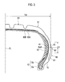
- Fig. 3 is a cross-sectional view, taken in a tire width direction, of the pneumatic tire according to the first embodiment.
- a pneumatic tire 1 includes paired bead portions 10 and a carcass layer 20.
- the paired bead portions 10 each include at least a bead core 10a and a bead filler 10b.
- the carcass layer 20 is provided between the paired bead cores 10a to make a toroidal shape and is folded from an inner side, in the tire width direction, of each bead core 10a to an outer side, in the tire width direction, of the bead core 10a along the outer circumference of the bead core 10a.
- crescent-shaped side reinforcing layers 40 are provided on an inner side of the carcass layer 20 to reinforce tire side portions 30, respectively.
- each tire side portion 30 is provided between one of edge portions, namely tread shoulders 81, of a tread portion 80 to be described later and the corresponding bead portion 10.
- An inner liner 50 is provided on an inner side, in the tire width direction, of the side reinforcing layers 40.
- the inner liner 50 is a rubber layer corresponding to a tube and having high airtightness.
- Radial protrusions 60 extending straight in a tire radial direction are provided on an outer side, in the tire width direction, of each of the carcass layer 20, namely, on a surface of each of the tire side portions 30 (called a tire surface 31 hereinbelow).
- the radial protrusions 60 each have a shape protruding from the tire surface 31 outward in the tire width direction.
- the multiple radial protrusions 60 are provided radially with a tire rotation axis S as the center. Note that details of the radial protrusions 60 will be described later.
- a rim guard 70 is provided on an outer side, in the tire width direction, of the carcass layer 20 near the corresponding bead portion 10.
- the rim guard 70 has a shape protruding from the tire surface 31 outward in the tire width direction.
- the tread portion 80 to be in contact with a road surface is provided on an outer side, in the tire radial direction, of the carcass layer 20.
- a first belt layer 90A and a second belt layer 90B are provided on an inner side in the tire radial direction and on an outer side in the tire radial direction, respectively.
- Fig. 4 is a perspective view of the radial protrusions according to the first embodiment.
- Fig. 5 shows the radial protrusion according to the first embodiment.
- Part (a) of Fig. 5 is a diagram, viewed in the direction of Arrow A in Fig. 4 , showing the radial protrusion according to the first embodiment.
- Part (b) of Fig. 5 is a diagram, viewed in the direction of Arrow B in Fig. 4 , showing the radial protrusion according to the first embodiment.
- each of the multiple radial protrusions 60 is formed to be substantially rectangular in a cross section taken in a direction substantially perpendicular to the tire radial direction (i.e., to the extending direction of the protrusion).
- the multiple radial protrusions 60 each have an inner end portion 61 being an end portion located at an inner side thereof in the tire radial direction and an outer end portion 62 being an end portion located at an outer side thereof in the tire radial direction.
- the inner end portion 61 continues smoothly into the surface of the rim guard 70.
- the outer end portion 62 inclines to smoothly continue into the tire surface 31.
- the outer end portion 62 is provided in a portion corresponding to a tire maximum width TW (called a maximum width portion T hereinbelow) in the tire surface 31.
- the maximum width portion T refers to an area extending from a point 10 mm away from a point TWP corresponding to the tire maximum width TW toward an inner side in the tire radial direction to a point 10 mm away from the point TWP toward an outer side in the tire radial direction (see Fig. 3 ). Since the outer end portions 62 are provided in this area, even if the tire side portions 30 are deformed when the pneumatic tire 1 runs flat (runs with a tire internal pressure of 0 kPa), the radial protrusions 60 do not come in contact with the road surface. As a result, the radial protrusions 60 do not suffer from friction heat, and therefore the temperature rise in the tire side portions 30 can be suppressed.
- the outer end portion 62 has an end face 62A at an outer side in the tire radial direction.
- the end face 62A inclines ( ⁇ ) with respect to the tire surface 31. Specifically, the height of the outer end portion measured in the tire width direction decreases toward an outer side in the tire radial direction. In other words, the angle formed between the end face 62A and the tire surface 31 is constant.
- the maximum height of each radial protrusion 60 measured in the tire width direction (called a radial-protrusion height h hereinbelow) is preferably 0.5 mm to 7 mm, both inclusive.
- the radial-protrusion height h When the radial-protrusion height h is 0.5 mm or larger, airflow crosses over the radial protrusion 60 and flows toward the tire surface 31 in a direction substantially perpendicular thereto. Such airflow flowing toward the tire surface 31 in the direction substantially perpendicular thereto (so-called downflow) collides heavily with the tire surface 31 at a position between the radial protrusions 60, allowing the airflow and the tire surface 31 to actively exchange heat with each other. Thereby, the temperature rise in the tire side portion 30 can be efficiently suppressed.
- the radial-protrusion height h when the radial-protrusion height h is 7 mm or smaller, the radial protrusions 60 can be provided with enough rigidity. This can further improve the durability of the radial protrusions 60.
- each radial protrusion 60 measured in a direction substantially perpendicular to the tire radial direction (to the extending direction of the protrusion) (called a radial-protrusion width w) is constant in the tire radial direction.
- the radial-protrusion width w is preferably 0.3 mm to 4 mm, both inclusive.
- the radial-protrusions 60 can be provided with enough rigidity. Thereby, the durability of the radial protrusions 60 can be further improved.
- the radial-protrusion width w is 4 mm or smaller, the internal temperature of (the temperature of heat accumulated in) the radial protrusions 60 can be decreased. Thereby, the temperature rise in the tire side portion 30 can be efficiently suppressed.
- Fig. 6 is an enlarged side view of the radial protrusion according to the first embodiment.
- an angle between the tire radial direction and the direction in which the radial protrusion 60 extends is preferably set within a range of -70° ⁇ ⁇ ⁇ 70°.
- Fig. 7 is a partial perspective view of the radial protrusions according to the first embodiment.
- Fig. 8 is a cross-sectional view of the radial protrusions according to the first embodiment (taken in the C-C line in Fig. 7 ).
- the radial protrusions 60 preferably have a relation of 1.0 ⁇ p/h ⁇ 50.0 and 1.0 ⁇ (p-w) /w ⁇ 100.0, where "h” is the radial protrusion height, "w” is the radial-protrusion width, and “p” is the pitch between the radial protrusions 60 adjacent to each other.
- the pitch p indicates a distance between the center of the radial-protrusion width w of one radial protrusion 60 and the center of the radial-protrusion width w of an adjacent radial protrusion 60, the distance being measured at their outer end portions 62 (end faces 62A).
- the radial protrusions 60 have a relation of 2. 0 ⁇ p/h ⁇ 24. 0 and 4. 0 ⁇ (p-w) /w ⁇ 39. 0. It is even more preferably that the radial protrusions 60 have a relation of 10.0 ⁇ p/h ⁇ 20.0 and 4.0 ⁇ (p-w)/w ⁇ 39.0.
- the radio of a difference between the pitch p and the radial-protrusion width w to the radial-protrusion width w ((p-w)/w) is larger than 1.0
- the radiation area is larger than the surface areas (top faces 60A) of the radial protrusions 60.
- the temperature rise in the tire side portion 30 is suppressed.
- FIG. 9 is a diagram illustrating flow of air crossing over the radial protrusions 60 according to the first embodiment.
- FIG. 9 shows, airflow flowing on the tire side portion 30 (the tire surface 31) crosses over multiple radial protrusions 60.
- airflow S1 generated by the rotation of the pneumatic tire 1 is separated from the tire surface 31 by the radial protrusions 60.
- the airflow S1 separated from the tire surface 31 crosses over an edge portion E of the radial protrusion 60 located on a front side of the radial protrusion 60 in the tire rotation direction.
- the airflow S1 having crossed over the radial protrusion 60 flows toward the tire surface 31 in the direction substantially perpendicular thereto at a position behind the radial protrusion 60 in the tire rotation direction (i.e., becomes so-called downflow).
- the airflow S1 collides heavily with the tire surface 31, and travels toward the adjacent radial protrusion 60.
- fluid S2 staying behind the radial protrusion 60 in the tire rotation direction draws heat staying there and joins the airflow S1.
- fluid S3 staying before the adjacent radial protrusions 60 in the tire rotation direction draws heat staying there and joins the airflow S1, as well.
- the airflow S1 flows toward the tire surface 31 in the direction substantially perpendicular thereto at a position behind the radial protrusion 60 in the tire rotation direction, and then collides heavily with the tire surface 31. Further, the fluid S2 and the fluid S3 having drawn heat join the airflow S1. Accordingly, the airflow S1 and the tire surface 31 actively exchange heat with each other, decreasing the temperature rise in the tire side portions 30 in a large area.
- the pneumatic tire 1 includes the multiple radial protrusions 60 protruding from the tire surface 31 outward in the tire width direction.
- the airflow S1 flowing on the tire side portion 30 (the tire surface 31) crosses over the radial protrusion 60.
- the airflow S1 then flows toward the tire surface 31 in the direction substantially perpendicular thereto at a position behind the radial protrusion 60 in the tire rotation direction, and collides heavily with the tire surface 31. Consequently, the airflow S1 and the tire surface 31 actively exchange heat with each other, sufficiently suppressing the temperature rise in the tire side portion 30 (the tire surface 31).
- the durability of the tire improves.
- the outer end portions 62 are provided in the maximum width portion T. Accordingly, even if the tire side portions 30 are deformed when the pneumatic tire 1 runs flat (runs with a tire internal pressure of 0 kPa), the radial protrusions 60 do not come in contact with the road surface. As a result, the radial protrusions 60 do not suffer from friction heat, sufficiently suppressing the temperature rise in the tire side portion 30 (the tire surface 31). In addition, since the radial protrusions 60 are not chipped or removed, the visibility for the pneumatic tire 1 is not lowered.
- the radial-protrusion height h is 0.5 mm to 7 mm, both inclusive
- the radial-protrusion width w is 0.3 mm to 4 mm, both inclusive. Accordingly, the airflow S1 flowing toward the tire surface 31 in the direction substantially perpendicular thereto (downflow) collides heavily with the tire surface 31 at a position behind the radial protrusion 60 in the tire rotation direction. Accordingly, the airflow S1 and the tire surface 31 actively exchange heat with each other to further suppress the temperature rise in the tire side portions 30.
- the extending-direction angle ( ⁇ ) is set within the range of -70° ⁇ ⁇ ⁇ 70°. Accordingly, the airflow S1 flows easily over the multiple radial protrusions 60. Consequently, the airflow S1 and the tire surface 31 actively exchange heat with each other, further suppressing the temperature rise in the tire side portion 30.
- the radial protrusions 60 are set to have a relation of 1.0 ⁇ p/h ⁇ 50. 0 and 1.0 ⁇ (p-w)/w ⁇ 100.0. This allows the airflow S1 and the tire surface 31 to actively exchange heat with each other, decreasing the temperature rise in the tire side portion 30 in a large area.
- the end face 62A according to the first embodiment has a constant angle with respect to the tire surface 31.
- the following modification may be made.
- the same portions as those of the pneumatic tire 1 according to the first embodiment are denoted by the same reference signs. Different portions are mainly described.
- Fig. 11 is an enlarged side view of a radial protrusion according to Modification 1.
- the outer end portion 62 has an end face 62A at an outer side thereof in the tire radial direction.
- This end face 62A has a varying angle ( ⁇ ) with respect to the tire surface 31.
- the height of the outer end portion measured in the tire width direction only needs to decrease toward an outer side in the tire radial direction.
- the end face 62A according to the first embodiment inclines with respect to the tire surface 31.
- the following modification may be made.
- the same portions as those of the pneumatic tire 1 according to the first embodiment are denoted by the same reference signs. Different portions are mainly described.
- Fig. 12 is an enlarged side view of a radial protrusion according to Modification 2.
- the outer end portion 62 has an end face 62A at an outer side thereof in the tire radial direction.
- This end face 62A has an angle of 90° with respect to the tire surface 31.
- the end face 62A only needs to form an angle larger than 0° but not exceeding 90°.
- the radial-protrusion width w according to the first embodiment is constant in the tire radial direction.
- the following modification may be made.
- the same portions as those of the pneumatic tire 1 according to the first embodiment are denoted by the same reference signs. Different portions are mainly described.
- Fig. 13 is a side view of a pneumatic tire according to Modification 3. As Fig. 13 shows, the radial-protrusion width w is not constant in the tire radial direction.
- the width of the inner end portion 61 measured in the direction substantially perpendicular to the tire radial direction (to the extending direction of the protrusion) is larger than the radial-protrusion width w of the radial protrusion 60 measured at its center portion in the tire radial direction.
- the width of the outer end portion 62 measured in the direction substantially perpendicular to the tire radial direction (to the extending direction of the protrusion) is larger than the radial-protrusion width w of the radial protrusion 60 measured at its center portion in the tire radial direction.
- the radial-protrusions 60 according to the first embodiment extend straight in the tire radial direction.
- the following modification may be made.
- the same portions as those of the pneumatic tire 1 according to the first embodiment are denoted by the same reference signs. Different portions are mainly described.
- Fig. 14 is a side view of a pneumatic tire according to Modification 4.
- the radial protrusions 60 each curve with respect to the tire radial direction.
- the extending-direction angle ( ⁇ ) largely changes from an inner side, in the tire radial direction, of the protrusion 60 to an outer side, in the tire radial direction, of the protrusion 60.
- the extending-direction angle ( ⁇ ) does not necessarily have to largely change from the inner side in the tire radial direction to the outer side in the tire radial direction.
- the extending-direction angle ( ⁇ ) may slightly change from the inner side in the tire radial direction to the outer side in the tire radial direction.
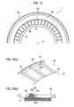
- Fig. 15 is a side view showing part of the pneumatic tire according to the second embodiment.
- Fig. 16 shows diagrams of radial protrusions according to the second embodiment.
- the same portions as those of the pneumatic tire 1 according to the first embodiment described above are denoted by the same reference signs. Different portions are mainly described.
- the configurations of the radial protrusions 60 are the same as that of the first embodiment.
- the pneumatic tire 1 includes not only the radial protrusions 60, but also a circular circumferential protrusion 100.
- the circular circumferential protrusion 100 extends along the circumference of a circle having the tire rotation axis S as the center, and has a shape protruding from the tire surface 31 outward in the tire width direction.
- the circular circumferential protrusion 100 is provided in the maximum width portion T.
- the circular circumferential protrusion 100 is formed to be substantially trapezoidal in a cross section taken in a direction substantially perpendicular to the tire circumferential direction (i.e., to the extending direction of the protrusion).
- the circular circumferential protrusion 100 has an inner face 101 located at its inner side in the tire radial direction and an outer face 102 located at its outer side in the tire radial direction.
- the inner face 101 inclines ( ⁇ ) with respect to the tire surface 31.
- the end face 62A of the outer end portion 62 forms an angle ( ⁇ ) larger than 90° with respect to the tire surface 31. Accordingly, the end face 62A is continuous with the inner face 101 which inclines with respect to the tire surface 31.
- the outer end portions 62 are each located at an outermost position in the tire radial direction. In other words, it should be noted that the outer end portions 62 only need to be provided in the maximum width portion T.
- the end face 62A of the outer end portion 62 may form an angle ( ⁇ ) larger than 90° with respect to the tire surface 31.
- the outer face 102 inclines ( ⁇ ) with respect to the tire surface 31.
- the outer face 102 does not necessarily have to incline with respect to the tire surface 31.
- the outer face 102 may form an angle of 90° with respect to the tire surface 31.
- the outer face 102 preferably forms an angle ( ⁇ ) equal to or larger than 90° but not exceeding 180° with respect to the tire surface 31.
- the height of the circular circumferential protrusion 100 measured in the tire width direction (called a circumferential-protrusion height hs) is preferably 0.2 times to 1.5 times, both inclusive, of the maximum height of each of the multiple radial protrusions measured in the tire width direction (i.e., the radial protrusion height h).
- the circumferential-protrusion height hs is 0.2 times or more of the radial-protrusion height h, airflow flowing on the maximum width portion T is prevented from being separated from the tire surface 31. Thereby, the temperature rise in the tire side portion 30 is sufficiently suppressed.
- the circumferential protrusion height hs is 1.5 times or less of the radial-protrusion height h, the circular circumferential protrusion 100 can be provided with enough rigidity. This further improves the durability of the circular circumferential protrusion 100.
- the width of the circular circumferential protrusion 100 measured in the tire radial direction (called a circumferential-protrusion width B) is preferably 2 mm to 22 mm.
- This circumferential protrusion width B does not necessarily have to be constant in the tire circumferential direction.
- the circumferential protrusion width B does not have to be constant in the tire circumferential direction.
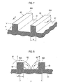
- Fig. 18 is a diagram illustrating flow of air crossing over the radial protrusions and a circular circumferential protrusion according to the second embodiment.
- Fig. 18 shows, in the tire side portion 30, the circumference is longer on an outer side in the tire radial direction than on an inner side in the tire radial direction. Accordingly, airflow flowing on an inner side, in the tire radial direction, of the point TWP corresponding to the tire maximum width TW (inner airflow) travels slower than air flowing on an outer side, in the tire radial direction, of the point TWP corresponding to the tire maximum width TW (outer air).
- the inner airflow is pulled by the outer airflow and is directed outward in the tire radial direction by the centrifugal force.
- the closer to the tire rotation axis S the larger an inclination angle ⁇ of airflow with respect to the tangent to the tire circumference.
- the inner airflow has a larger radial component directed in the tire radial direction and a smaller circumferential component directed in the tire circumferential direction than the outer airflow does.
- the pneumatic tire 1 has a shape with a curvature in a cross section taken in the tire width direction. Accordingly, the inner airflow having a large radial component is easily separated from the tire surface 31 (or easily moves away from the tire surface 31) in the tire radial direction.
- the pneumatic tire 1 further includes the circular circumferential protrusion 100. Accordingly, the inner airflow having a large radial component crosses over the circular circumferential protrusion 100 and is caught on the tire surface 31.
- airflow having crossed over the circular circumferential protrusion 100 flows toward the tire surface 31 in the direction substantially perpendicular thereto at a position outside of the circular circumferential protrusion 100 in the tire radial direction (i.e., outside of the point TWP corresponding to the tire maximum width TW in the tire radial direction) (i.e., becomes so-called downflow).
- the inner airflow having a large radial component is not easily separated from the tire surface 31.
- airflow flowing on the maximum width portion T is easily attached to the tire surface 31 at a position near the tire maximum width TW.
- airflow having a circumferential component flows toward the tire surface 31 in the direction substantially perpendicular thereto at a position behind the radial protrusions 60 in the tire rotation direction, and collides heavily with the tire surface 31 (see Fig. 8 ).
- the fluid S2 and the fluid S3 each having drawn heat join the airflow S1. This causes the airflow S1 and the tire surface 31 to actively exchange heat with each other, decreasing the temperature rise in the tire side portion 30 in a large area.
- the pneumatic tire 1 further includes the circular circumferential protrusion 100 extending in the circumferential direction. Accordingly, the inner airflow having a large radial component crosses over the circular circumferential protrusion 100 and is caught on the tire surface 31. Specifically, the airflow having crossed over the circular circumferential protrusion 100 flows toward the tire surface 31 in the direction substantially perpendicular thereto at a position outside of the circular circumferential protrusion 100 in the tire radial direction (i.e., become so-called downflow).
- the inner airflow having a large radial component i.e., airflow flowing on the maximum width portion T
- the airflow flowing on the maximum width portion T is easily attached to the tire surface 31 at a position near the tire maximum width TW. Since the airflow flowing on the maximum width portion T is retained on the tire surface 31, the airflow S1 and the tire surface 31 can actively exchange heat with each other.
- the inner face 101 according to the second embodiment inclines with respect to the tire surface 31.
- the following modification may be made.
- the same portions as those of the pneumatic tire 1 according to the second embodiment are denoted by the same reference signs. Different portions are mainly described.
- Fig. 19 is an enlarged side view of a radial protrusion according to Modification 1.
- the inner face 101 curves with respect to the tire surface 31.
- the end face 62A of the outer end portion 62 curves with respect to the tire surface 31.
- the end face 62A is continuous with the curving inner face 101. Accordingly, it should be noted that the inner face 101 does not necessarily have to have a constant angle ( ⁇ ) with respect to the tire surface 31.
- the outer face 102 inclines ( ⁇ ) with respect to the tire surface 31.
- the outer face 102 does not necessarily have to incline with respect to the tire surface 31, and may have, for example, an angle ( ⁇ ) of 90° with respect to the tire surface 31, as shown in part (b) of Fig. 19 .
- the outer face 102 preferably forms an angle ( ⁇ ) equal to or larger than 90 ° but not exceeding 180° with respect to the tire surface 31.
- the circular circumferential protrusion 100 according to the second embodiment is formed to be substantially trapezoidal in a cross section taken in the direction substantially perpendicular to the tire circumferential direction (i.e., to the extending direction of the protrusion).
- the following modification may be made.
- the same portions as those of the pneumatic tire 1 according to the second embodiment are denoted by the same reference signs. Different portions are mainly described.
- Fig. 20 shows enlarged side views of a radial protrusion according to Modification 2.
- the circular circumferential protrusion 100 is formed to be substantially quadrangular in a cross section taken in the direction substantially perpendicular to the tire circumferential direction (i.e., to the extending direction of the protrusion).
- the circular circumferential protrusion 100 has the inner face 101 located on its inner side in the tire radial direction and an outer face 102 located on its outer side in the tire radial direction.
- the inner face 101 forms an angle ( ⁇ ) of 90° with respect to the tire surface 31.
- the end face 62A of the outer end portion 62 forms an angle ( ⁇ ) of 90° with respect to the tire surface 31.
- the end face 62A is continuous with the inner face 101 forming an angle ( ⁇ ) of 90° with respect to the tire surface 31.
- the inner face 101 preferably forms an angle ( ⁇ ) equal to or larger than 90° but not exceeding 180° with respect to the tire surface 31.
- the outer face 102 forms an angle ( ⁇ ) of 90° with respect to the tire surface 31.
- the outer face 102 does not necessarily have to form an angle of 90° with respect to the tire surface 31, and, for example, may incline with respect to the tire surface 31, as shown in part (b) of Fig. 20 .
- the outer face 102 preferably forms an angle ( ⁇ ) equal to or larger than 90° but not exceeding 180° with respect to the tire surface 31.
- the radial-protrusion width w according to the second embodiment is constant in the tire radial direction.
- the following modification may be made.
- the same portions as those of the pneumatic tire 1 according to the second embodiment are denoted by the same reference signs. Different portions are mainly described.
- Fig. 21 is a side view of a pneumatic tire according to Modification 3. As Fig. 21 shows, the radial-protrusion width w is not constant in the tire radial direction.
- the width of the inner end portion 61 measured in the direction substantially perpendicular to the tire radial direction (to the extending direction of the protrusion) is larger than the radial-protrusion width w of the radial protrusion 60 measured at its center portion in the tire radial direction.
- the inner end portion 61 continues into the rim guard 70 by a large width.
- the width of the outer end portion 62 measured in a direction substantially perpendicular to the tire radial direction (to the extending direction of the protrusion) is larger than the radial-protrusion width w of the radial protrusion 60 measured at its center portion in the tire radial direction. In other words, the outer end portion 62 continues into the circular circumferential protrusion 100 by a large width.
- the radial-protrusions 60 according to the second embodiment extend straight in the tire radial direction.
- the following modification may be made.
- the same portions as those of the pneumatic tire 1 according to the first embodiment are denoted by the same reference signs. Different portions are mainly described.
- Fig. 22 is a side view of a pneumatic tire according to Modification 4.
- the radial protrusions 60 each curve with respect to the tire radial direction.
- the extending-direction angle ( ⁇ ) largely changes from an inner side, in the tire radial direction, of the protrusion 60 to an outer side, in the tire radial direction, of the protrusion 60.
- the extending-direction angle ( ⁇ ) does not necessarily have to largely change from the inner side in the tire radial direction to the outer side in the tire radial direction.
- the extending-direction angle ( ⁇ ) may slightly change from the inner side in the tire radial direction to the outer side in the tire radial direction.
- the inner end portions 61 of the multiple radial protrusions 60 smoothly continue into the rim guard 70.
- the present invention is not limited to such a case.
- the inner end portions 61 of the multiple radial protrusions 60 may be separated from the rim guard 70.
- the rim guard 70 does not necessarily have to be provided on the tire surface 31.
- the multiple radial protrusions 60 are each formed to be substantially quadrangular in a cross section taken in the direction substantially perpendicular to the tire radial direction (to the extending direction of the protrusions).
- the present invention is not limited to such a case.
- the multiple radial protrusions 60 may be formed to be substantially triangular or substantially trapezoidal.
- the height of the radial protrusions 60 (the radial-protrusion height h) and the height of the circular circumferential protrusion 100 (the circumferential protrusion height hs) do not necessarily have to be constant.
- Corner portions of each radial protrusion 60 may be round.
- a border between the top face and the end face 62A of each radial protrusion 60 may be round.
- the pneumatic tire 1 has the side reinforcing layers 40 (namely, is a run-flat tire).
- the present invention is not limited to such a case.
- the pneumatic tire 1 does not have to have the side reinforcing layers 40.
- Example 1 Example 2
- Example 3 Example 4
- Example 5 Example 6 (type of tire) only with radial protrusions (radial pattern) radial protrusions (provided inside of maximum width in tire radial direction) ⁇ radial protrusions + circumferential protrusion ⁇ ⁇ radial protrusions + circumferential protrusion p/h 15 ⁇ ⁇ ⁇ ⁇ 15 (p-w)/w 29 ⁇ ⁇ ⁇ ⁇ 29 w (mm) 2 ⁇ ⁇ ⁇ ⁇ 2 h (mm) 2 ⁇ ⁇ ⁇ ⁇ 2 circumferential protrusion portion absent absent present ⁇ ⁇ ⁇ height hs (mm) - - 1.2 0.4 2.4 3.0 3.2 hs/h (index) - - 0.6 0.2 1.2 1.5 1.6 width B (mm) -
- the pneumatic tire according to Comparative Example 1 does not include protrusions (the radial protrusions 60 and the circular circumferential protrusion 100) on the tire surface.
- the outer end portions 62 of the radial protrusions 60 are provided outside of the maximum width portion T in the tire radial direction.
- the pneumatic tire according to Example 1 includes the radial protrusions 60 described in the first embodiment. Accordingly, in the pneumatic tire according to Example 1, the outer end portions 62 of the radial protrusions 60 are provided in the maximum width portion T. As Figs. 2 and 3 show, the pneumatic tires according to Examples 2 to 10 each include the radial protrusions 60 described in the first embodiment and the circular circumferential protrusion 100 described in the second embodiment.
- Each pneumatic tire was mounted on a test drum and was run until the pneumatic tire broke (e.g., until a separation occurred near the side reinforcing layers). The durability distance is thus measured and then expressed as an index number. Using the durability of the pneumatic tire according to Comparative Example 2 as the reference of 100, the durability of each of the other pneumatic tires was evaluated. The larger the numeric value, the better the durability.
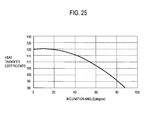
- Figs. 23 to 25 show results of durability tests conducted while changing p/h, (p-w)/w, and the extending-direction angle ( ⁇ ) of the turbulence generating protrusions.
- the vertical axis of the graph in each of Figs. 23 to 25 indicates a heat transfer coefficient.
- the heat transfer coefficient was obtained by: applying a constant voltage to a heater to generate a certain amount of heat; blowing the heat with a blower, and measuring the temperature of the tire surface and the amount of air blown. Accordingly, the larger the heat transfer coefficient, the higher the radiation effect of the tire side portion, namely, the better the durability.
- the heat transfer coefficient of the pneumatic tire which is not provided with either the radial protrusions 60 or the circular circumferential protrusion 100 is set to "100".
- the heat transfer coefficient measuring tests were conducted under the following conditions.
- the heat transfer coefficient is high when the ratio of the pitch P of the radial protrusions to the radial-protrusion height h (p/h) is 1.0 to 50.0.
- p/h is 2.0 to 24.0, the heat transfer coefficient is even higher.
- the graph shows that it is particularly preferable to provide the radial protrusions with a relation of 2.0 ⁇ p/h ⁇ 24.0, or even more preferably, with a relation of 10.0 ⁇ p/h ⁇ 20.0.
- Fig. 24 shows that, based on the relation between (p-w) /w and the heat transfer coefficient (measured in the same manner as that for the above heat transfer coefficient), the radial protrusions should be provided with a relation of 1.0 ⁇ (p-w) /w ⁇ 100.0.
- the graph shows that it is particularly preferable to provide the radial protrusions with a relation of 4.0 ⁇ (p-w)/w ⁇ 39.0.
- Fig. 25 shows that it is preferable to provide the radial protrusions so that the extending direction angle ( ⁇ ) may be within a range of 0 to 70°. Note that similar heat transfer coefficient should be obtained even when the extending direction angle ( ⁇ ) is set within a range of 0 to -70°.
- the pneumatic tire according to the present invention can sufficiently suppress the temperature rise in the tire side potions, and is therefore useful in a technique for manufacturing pneumatic tires, and the like.
- 1 ⁇ pneumatic tire 10 ⁇ bead portion, 10a ⁇ bead core, 10b ⁇ bead filler, 20 ⁇ carcass layer, 30 ⁇ tire side portion, 31 ⁇ tire surface, 40 ⁇ side reinforcing layer, 50 ⁇ inner liner, 60 ⁇ radial protrusion, 60A ⁇ top face, 61 ⁇ inner end portion, 62 ⁇ outer end portion, 62A ⁇ end face, 70 ⁇ rim guard, 80 ⁇ tread portion, 81 ⁇ tread shoulder, 90A ⁇ first belt layer, 90B ⁇ second belt layer, 100 ⁇ circular circumferential protrusion, 101 ⁇ inner face, 102 ⁇ outer face
Abstract
Description
- The present invention relates to a pneumatic tire provided with multiple radial protrusions extending in a tire radial direction on a tire surface thereof.
- Generally, a rise in the temperature of a pneumatic tire promotes a time-dependent change in a material constituting the pneumatic tire. An example of the time-dependent change in the material is a change in properties. The temperature rise in the pneumatic tire can also cause damage in a tread portion at high-speed driving. For those reasons, the temperature rise in the pneumatic tire is not desirable in terms of the durability of the pneumatic tire.
- An improvement in the durability is important particularly for an off-the-road radial tire (ORR) and a truck and bus radial tire (TBR) that receive a heavy load, as well as a run-flat tire running flat (running with a tire internal pressure of 0 kPa). Accordingly, it is important for these pneumatic tires to have a reduced temperature rise.
- For example, the run-flat tire is provided with sidewall reinforcing layers for reinforcing tire side portions. The sidewall reinforcing layers each have a crescent shape in a cross section taken in a tire width direction. When the run-flat tire runs flat, deformation in a tire radial direction concentrates on the sidewall reinforcing layers. Thereby, the sidewall reinforcing layers have an increased temperature, consequently deteriorating the durability of the run-flat tire.
- On the other hand, there has been proposed a technique in which reinforcing members for suppressing deformation of the pneumatic tire are provided to a carcass layer and bead portions (called a first technique below) (e.g., Patent Literature 1). In the first technique, the reinforcing members for suppressing deformation in side portions are provided particularly to the carcass layer and the bead portions that constitute the tire side portions. Thereby, the temperature rise in the pneumatic tire, or particularly, the temperature rise in the tire side portions can be suppressed.
- There is known a technique in which a rim guard having many ridges is provided outside, in the tire width direction, of each bead portion adjacent to a rim (called a second technique below). The surface area of the pneumatic tire is increased by the many ridges provided to the rum guard, improving the radiation performance of heat generated in the pneumatic tire.
- Patent Literature 1: Japanese Patent Application Publication No.
2006-76431 - In the first technique described above, a load applied to the pneumatic tire might lead to a separation of the reinforcing members. In other words, the reinforcing member might be a factor for other damage.
- Moreover, the reinforcing members provided to the tire side portions improve the rigidity of the tire side portions, and therefore make the pneumatic tire more bouncy. This consequently might degrade the steering stability, ride quality, and the like. The run-flat tire, in particular, has high rigidity in the tire side portions; therefore, the ride quality and the like might be degraded.
- As described, the intention of the second technique described above is to improve the radiation performance by increasing the surface area of the pneumatic tire. Meanwhile, the outer surface of the pneumatic tire is preferably made of a rubber material having low heat conductivity such as to prevent conduction of friction heat generated between the pneumatic tire and the road surface. Accordingly, the temperature rise in the tire side portions cannot be sufficiently suppressed by simply increasing the surface area of the pneumatic tire.
- The present invention has been made to solve the above problems, and has an objective of providing a pneumatic tire capable of sufficiently suppressing the temperature rise in the tire side portions.
- To solve the above problems, the present invention has the following aspects. The first aspect of the present invention is summarized as a pneumatic tire comprising a plurality of radial protrusions (radial protrusions 60) each extending in a tire radial direction on a tire surface (tire surface 31) and having a shape protruding from the tire surface outward in a tire width direction, wherein the plurality of radial protrusions are provided radially with a tire rotation axis as a center, the plurality of radial protrusions each have an outer end portion (outer end portion 62) being an end portion located on an outer side in the tire radial direction, and the outer end portion is provided to the tire surface in a tire maximum width portion (maximum width portion T) in the tire width direction.
- According to the above aspect, the pneumatic tire has the multiple radial protrusions protruding from the tire surface outward in the tire width direction. Accordingly, airflow flowing on the tire side portion (the tire surface) crosses over the radial protrusion. Then, the airflow flows toward the tire surface in the direction substantially perpendicular thereto at a position behind the radial protrusion in the tire rotation direction, and then collides heavily with the tire surface. Consequently, the airflow and the tire surface actively exchange heat with each other, sufficiently suppressing the temperature rise in the tire side portion (tire surface). This, as a result, improves the durability of the tire.
- Here, assume that the outer end portions of the radial protrusions are provided outside the maximum width portion in the tire radial direction. In this case, if the tire side portions are deformed when the pneumatic tire runs flat (runs with a tire internal pressure of 0 kPa), the radial protrusions come in contact with the road surface. As a result, the radial protrusions suffer from friction heat, increasing the temperature in the tire side portion. Moreover, friction between the radial protrusions and the road surface might chip or remove the radial protrusions. This consequently lowers the visibility for the pneumatic tire.
- With this taken into consideration, the outer end portions are provided in the maximum width portion. Accordingly, even if the tire side portions are deformed when the pneumatic tire runs flat (runs with a tire internal pressure of 0 kPa), the radial protrusions do not come in contact with the road surface. As a result, the radial protrusions do not suffer from friction heat, sufficiently suppressing the temperature rise in the tire side portion (the tire surface). In addition, since the radial protrusions are not chipped or removed, the visibility for the
pneumatic tire 1 is not lowered. - The other aspect is summarized that a width of the tire maximum width portion measured in the tire radial direction is within a range of 10 mm on each of outer and inner sides, in the tire radial direction, of a tire maximum width point.
- The other aspect is summarized as further comprising a circular circumferential protrusion extending along a circumference which has the tire rotation axis as a center and having a shape protruding outward in the tire width direction, wherein the circular circumferential protrusion is provided in the tire maximum width portion.
- The other aspect is summarized that a height of the circular circumferential protrusion measured in the tire width direction is 0.2 times to 1.5 times, both inclusive, of a maximum height of each of the plurality of radial protrusions measured in the tire width direction.
- The other aspect is summarized that a width of the circular circumferential protrusion measured in the tire radial direction is 2 mm to 22 mm, both inclusive.
- The other aspect is summarized that the outer end portion has an end face on the outer side in the tire radial direction, and the end face forms an angle larger than 0° but not exceeding 90° with respect to the tire surface.
- The other aspect is summarized that a height of the outer end portion measured in the tire width direction decreases toward the outer side in the tire radial direction.
- The other aspect is summarized that the plurality of radial protrusions have a relation of 1.0 ≤ p/h ≤ 50. 0 and 1.0 ≤ (p-w) /w ≤ 100.0, where "h" is a maximum height of each radial protrusion measured in the tire width direction, "w" is a width of each radial protrusion measured in a direction perpendicular to the tire radial direction, and "p" is a pitch between the adjacent radial protrusions.
- The present invention can provide a pneumatic tire capable of sufficiently suppressing the temperature rise in the tire side portions.
-
- [
Fig. 1] Fig. 1 is a side view of a pneumatic tire according to a first embodiment. - [
Fig. 2] Fig. 2 is a partial cross-sectional perspective view of the pneumatic tire according to the first embodiment. - [
Fig. 3] Fig. 3 is a cross-sectional view of the pneumatic tire according to the first embodiment, taken in a tire width direction. - [
Fig. 4] Fig. 4 is a perspective view of radial protrusions according to the first embodiment. - [
Fig. 5] Fig. 5 is a diagram of radial protrusions according to the first embodiment. - [
Fig. 6] Fig. 6 is an enlarged side view of the radial protrusion according to the first embodiment. - [
Fig. 7] Fig. 7 is a partial perspective view of the radial protrusions according to the first embodiment. - [
Fig. 8] Fig. 8 is a cross-sectional view of the radial protrusions according to the first embodiment (taken along a C-C line inFig. 7 ). - [
Fig. 9] Fig. 9 is a diagram illustrating flow of air crossing over the radial protrusions according to the first embodiment. - [
Fig. 10] Fig. 10 shows diagrams illustrating advantageous effects of the radial protrusions according to the first embodiment. - [
Fig. 11] Fig. 11 is an enlarged side view of a radial protrusion according toModification 1 of the first embodiment. - [
Fig. 12] Fig. 12 is an enlarged side view of a radial protrusion according toModification 2 of the first embodiment. - [
Fig. 13] Fig. 13 is a side view of a pneumatic tire according to Modification 3 of the first embodiment. - [
Fig. 14] Fig. 14 is a side view of a pneumatic tire according to Modification 4 of the first embodiment. - [
Fig. 15] Fig. 15 is a side view showing part of a pneumatic tire according to a second embodiment. - [
Fig. 16] Fig. 16 shows diagrams of radial protrusions according to the second embodiment. - [
Fig. 17] Fig. 17 is an enlarged side view of the radial protrusion according to the second embodiment. - [
Fig. 18] Fig. 18 shows diagrams illustrating flow of air crossing over the radial protrusions and a circular circumferential protrusion according to the second embodiment. - [
Fig. 19] Fig. 19 shows enlarged side views of a radial protrusion according toModification 1 of the second embodiment. - [
Fig. 20] Fig. 20 shows enlarged side views of a radial protrusion according toModification 2 of the second embodiment. - [
Fig. 21] Fig. 21 is a side view of a pneumatic tire according to Modification 3 of the second embodiment. - [
Fig. 22] Fig. 22 is a side view of a pneumatic tire according to Modification 4 of the second embodiment. - [
Fig. 23] Fig. 23 is a graph showing heat transfer coefficients of a pneumatic tire of Example (part 1). - [
Fig. 24] Fig. 24 is a graph showing heat transfer coefficients of a pneumatic tire of Example (part 2). - [
Fig. 25] Fig. 25 is a graph showing heat transfer coefficients of a pneumatic tire of Example (part 3). - Examples of a pneumatic tire according to the present invention will be described with reference to the drawings. Note that, in the following description of the drawings, same or similar reference signs denote same or similar elements and portions.
- In addition, it should be noted that the drawings are schematic and ratios of dimensions and the like are different from actual ones. Therefore, specific dimensions and the like should be determined in consideration of the following description. Moreover, the drawings also include portions having different dimensional relationships and ratios from each other.
- First, the configuration of a pneumatic tire according to a first embodiment is described with reference to the drawings.
Fig. 1 is a side view of the pneumatic tire according to the first embodiment.Fig. 2 is a partial cross-sectional perspective view of the pneumatic tire according to the first embodiment.Fig. 3 is a cross-sectional view, taken in a tire width direction, of the pneumatic tire according to the first embodiment. - As
Figs. 1 to 3 show, apneumatic tire 1 includes pairedbead portions 10 and acarcass layer 20. The pairedbead portions 10 each include at least abead core 10a and abead filler 10b. In the tire width direction, thecarcass layer 20 is provided between the pairedbead cores 10a to make a toroidal shape and is folded from an inner side, in the tire width direction, of eachbead core 10a to an outer side, in the tire width direction, of thebead core 10a along the outer circumference of thebead core 10a. - In a cross section taken in the tire width direction, crescent-shaped
side reinforcing layers 40, made of rubber stock, are provided on an inner side of thecarcass layer 20 to reinforcetire side portions 30, respectively. Note that eachtire side portion 30 is provided between one of edge portions, namely treadshoulders 81, of atread portion 80 to be described later and thecorresponding bead portion 10. - An
inner liner 50 is provided on an inner side, in the tire width direction, of the side reinforcing layers 40. Theinner liner 50 is a rubber layer corresponding to a tube and having high airtightness.Radial protrusions 60 extending straight in a tire radial direction are provided on an outer side, in the tire width direction, of each of thecarcass layer 20, namely, on a surface of each of the tire side portions 30 (called atire surface 31 hereinbelow). Theradial protrusions 60 each have a shape protruding from thetire surface 31 outward in the tire width direction. The multipleradial protrusions 60 are provided radially with a tire rotation axis S as the center. Note that details of theradial protrusions 60 will be described later. - A
rim guard 70 is provided on an outer side, in the tire width direction, of thecarcass layer 20 near the correspondingbead portion 10. Therim guard 70 has a shape protruding from thetire surface 31 outward in the tire width direction. - The
tread portion 80 to be in contact with a road surface is provided on an outer side, in the tire radial direction, of thecarcass layer 20. Between thecarcass layer 20 and thetread portion 80, afirst belt layer 90A and asecond belt layer 90B are provided on an inner side in the tire radial direction and on an outer side in the tire radial direction, respectively. - Next, the configuration of the
radial protrusions 60 described above is described with reference to the drawings.
Fig. 4 is a perspective view of the radial protrusions according to the first embodiment.Fig. 5 shows the radial protrusion according to the first embodiment. - Part (a) of
Fig. 5 is a diagram, viewed in the direction of Arrow A inFig. 4 , showing the radial protrusion according to the first embodiment. Part (b) ofFig. 5 is a diagram, viewed in the direction of Arrow B inFig. 4 , showing the radial protrusion according to the first embodiment. - As
Figs. 4 and 5 show, each of the multipleradial protrusions 60 is formed to be substantially rectangular in a cross section taken in a direction substantially perpendicular to the tire radial direction (i.e., to the extending direction of the protrusion). The multipleradial protrusions 60 each have aninner end portion 61 being an end portion located at an inner side thereof in the tire radial direction and anouter end portion 62 being an end portion located at an outer side thereof in the tire radial direction. - The
inner end portion 61 continues smoothly into the surface of therim guard 70. Theouter end portion 62, on the other hand, inclines to smoothly continue into thetire surface 31. Theouter end portion 62 is provided in a portion corresponding to a tire maximum width TW (called a maximum width portion T hereinbelow) in thetire surface 31. - The maximum width portion T refers to an area extending from a
point 10 mm away from a point TWP corresponding to the tire maximum width TW toward an inner side in the tire radial direction to apoint 10 mm away from the point TWP toward an outer side in the tire radial direction (seeFig. 3 ). Since theouter end portions 62 are provided in this area, even if thetire side portions 30 are deformed when thepneumatic tire 1 runs flat (runs with a tire internal pressure of 0 kPa), theradial protrusions 60 do not come in contact with the road surface. As a result, theradial protrusions 60 do not suffer from friction heat, and therefore the temperature rise in thetire side portions 30 can be suppressed. - The
outer end portion 62 has anend face 62A at an outer side in the tire radial direction. The end face 62A inclines (α) with respect to thetire surface 31. Specifically, the height of the outer end portion measured in the tire width direction decreases toward an outer side in the tire radial direction. In other words, the angle formed between the end face 62A and thetire surface 31 is constant. - The maximum height of each
radial protrusion 60 measured in the tire width direction (called a radial-protrusion height h hereinbelow) is preferably 0.5 mm to 7 mm, both inclusive. - When the radial-protrusion height h is 0.5 mm or larger, airflow crosses over the
radial protrusion 60 and flows toward thetire surface 31 in a direction substantially perpendicular thereto. Such airflow flowing toward thetire surface 31 in the direction substantially perpendicular thereto (so-called downflow) collides heavily with thetire surface 31 at a position between theradial protrusions 60, allowing the airflow and thetire surface 31 to actively exchange heat with each other. Thereby, the temperature rise in thetire side portion 30 can be efficiently suppressed. On the other hand, when the radial-protrusion height h is 7 mm or smaller, theradial protrusions 60 can be provided with enough rigidity. This can further improve the durability of theradial protrusions 60. - The width of each
radial protrusion 60 measured in a direction substantially perpendicular to the tire radial direction (to the extending direction of the protrusion) (called a radial-protrusion width w) is constant in the tire radial direction. The radial-protrusion width w is preferably 0.3 mm to 4 mm, both inclusive. - When the radial-protrusion width w is 0.3 mm or larger, the
radial protrusions 60 can be provided with enough rigidity. Thereby, the durability of theradial protrusions 60 can be further improved. On the other hand, when the radial-protrusion width w is 4 mm or smaller, the internal temperature of (the temperature of heat accumulated in) theradial protrusions 60 can be decreased. Thereby, the temperature rise in thetire side portion 30 can be efficiently suppressed. - Next, with reference to a drawing, the extending direction of the
radial protrusions 60 is described.Fig. 6 is an enlarged side view of the radial protrusion according to the first embodiment. - As
Fig. 6 shows, an angle between the tire radial direction and the direction in which theradial protrusion 60 extends (an extending-direction angle θ) is preferably set within a range of -70° ≤ θ ≤ 70°. - When the extending-direction angle (θ) is set within the above range, airflow flowing toward the
tire surface 31 in the direction substantially perpendicular thereto (so-called downflow) is generated at a position behind (downstream of) theradial protrusion 60 in a tire rotation direction. As a result, the temperature rise in thetire side portion 30 can be efficiently suppressed. - Next, a relation between the
radial protrusions 60 adjacent to each other in a tire circumferential direction is described with reference to the drawings.Fig. 7 is a partial perspective view of the radial protrusions according to the first embodiment.Fig. 8 is a cross-sectional view of the radial protrusions according to the first embodiment (taken in the C-C line inFig. 7 ). - As
Figs. 7 and 8 show, theradial protrusions 60 preferably have a relation of 1.0 ≤ p/h ≤ 50.0 and 1.0 ≤ (p-w) /w ≤ 100.0, where "h" is the radial protrusion height, "w" is the radial-protrusion width, and "p" is the pitch between theradial protrusions 60 adjacent to each other. The pitch p indicates a distance between the center of the radial-protrusion width w of oneradial protrusion 60 and the center of the radial-protrusion width w of an adjacentradial protrusion 60, the distance being measured at their outer end portions 62 (end faces 62A). - It is particularly preferable that the
radial protrusions 60 have a relation of 2. 0 ≤ p/h ≤ 24. 0 and 4. 0 ≤ (p-w) /w ≤ 39. 0. It is even more preferably that theradial protrusions 60 have a relation of 10.0 ≤ p/h ≤ 20.0 and 4.0 ≤ (p-w)/w ≤ 39.0. - When the ratio of the pitch p to the radial-protrusion height h (p/h) is larger than 1.0, air crossing over the
radial protrusion 60 and then flowing toward thetire surface 31 in the direction substantially perpendicular thereto (so-called downflow) heavily collides with thetire surface 31 easily at a position between theradial protrusions 60. Consequently, the temperature rise in thetire side portion 30 is further suppressed. On the other hand, when the ratio of the pitch p to the radial-protrusion height h (p/h) is smaller than 20.0, air crossing over theradial protrusion 60 and then flowing toward thetire surface 31 in the direction substantially perpendicular thereto (so-called downflow) is generated more with respect to the radiation area. As a result, the temperature rise in thetire side portion 30 is further suppressed. - When the radio of a difference between the pitch p and the radial-protrusion width w to the radial-protrusion width w ((p-w)/w) is larger than 1.0, the radiation area is larger than the surface areas (top faces 60A) of the
radial protrusions 60. As a result, the temperature rise in thetire side portion 30 is suppressed. On the other hand, when the ratio of the difference between the pitch p and the radial-protrusion width w to the radial-protrusion width w ((p-w)/w) is smaller than 100.0, air crossing over theradial protrusion 60 and then flowing toward thetire surface 31 in the direction substantially perpendicular thereto (so-called downflow) is generated more than in a case where ((p-w)/w) is larger than 100.0. As a result, the temperature rise in thetire side portion 30 is further suppressed. - Next, flow of air crossing over the
radial protrusions 60 according to the first embodiment is described with reference to a drawing.Fig. 9 is a diagram illustrating flow of air crossing over theradial protrusions 60 according to the first embodiment. - As
Fig. 9 shows, airflow flowing on the tire side portion 30 (the tire surface 31) crosses over multipleradial protrusions 60. Specifically, asFig. 8 shows, airflow S1 generated by the rotation of thepneumatic tire 1 is separated from thetire surface 31 by theradial protrusions 60. The airflow S1 separated from thetire surface 31 crosses over an edge portion E of theradial protrusion 60 located on a front side of theradial protrusion 60 in the tire rotation direction. The airflow S1 having crossed over theradial protrusion 60 flows toward thetire surface 31 in the direction substantially perpendicular thereto at a position behind theradial protrusion 60 in the tire rotation direction (i.e., becomes so-called downflow). Then, the airflow S1 collides heavily with thetire surface 31, and travels toward the adjacentradial protrusion 60. - In this event, fluid S2 staying behind the
radial protrusion 60 in the tire rotation direction draws heat staying there and joins the airflow S1. On the other hand, fluid S3 staying before the adjacentradial protrusions 60 in the tire rotation direction draws heat staying there and joins the airflow S1, as well. - As described, the airflow S1 flows toward the
tire surface 31 in the direction substantially perpendicular thereto at a position behind theradial protrusion 60 in the tire rotation direction, and then collides heavily with thetire surface 31. Further, the fluid S2 and the fluid S3 having drawn heat join the airflow S1. Accordingly, the airflow S1 and thetire surface 31 actively exchange heat with each other, decreasing the temperature rise in thetire side portions 30 in a large area. - In the first embodiment, the
pneumatic tire 1 includes the multipleradial protrusions 60 protruding from thetire surface 31 outward in the tire width direction. The airflow S1 flowing on the tire side portion 30 (the tire surface 31) crosses over theradial protrusion 60. The airflow S1 then flows toward thetire surface 31 in the direction substantially perpendicular thereto at a position behind theradial protrusion 60 in the tire rotation direction, and collides heavily with thetire surface 31. Consequently, the airflow S1 and thetire surface 31 actively exchange heat with each other, sufficiently suppressing the temperature rise in the tire side portion 30 (the tire surface 31). Thus, the durability of the tire improves. - Here, a description is given of a case where the
outer end portions 62 of theradial protrusions 60 are provided outside the maximum width portion T in the tire radial direction. As shown inFig. 10 , if thetire side portions 30 are deformed when thepneumatic tire 1 runs flat (runs with a tire internal pressure of 0 kPa), theradial protrusions 60 come in contact with the road surface. As a result, theradial protrusions 60 suffer from friction heat, increasing the temperature in thetire side portions 30. Moreover, friction between theradial protrusions 60 and the road surface might chip or remove theradial protrusions 60. This consequently lowers the visibility for thepneumatic tire 1. - With this taken into consideration, in the first embodiment, the
outer end portions 62 are provided in the maximum width portion T. Accordingly, even if thetire side portions 30 are deformed when thepneumatic tire 1 runs flat (runs with a tire internal pressure of 0 kPa), theradial protrusions 60 do not come in contact with the road surface. As a result, theradial protrusions 60 do not suffer from friction heat, sufficiently suppressing the temperature rise in the tire side portion 30 (the tire surface 31). In addition, since theradial protrusions 60 are not chipped or removed, the visibility for thepneumatic tire 1 is not lowered. - In the first embodiment, the radial-protrusion height h is 0.5 mm to 7 mm, both inclusive, and the radial-protrusion width w is 0.3 mm to 4 mm, both inclusive. Accordingly, the airflow S1 flowing toward the
tire surface 31 in the direction substantially perpendicular thereto (downflow) collides heavily with thetire surface 31 at a position behind theradial protrusion 60 in the tire rotation direction. Accordingly, the airflow S1 and thetire surface 31 actively exchange heat with each other to further suppress the temperature rise in thetire side portions 30. - In the first embodiment, the extending-direction angle (θ) is set within the range of -70° ≤ θ ≤ 70°. Accordingly, the airflow S1 flows easily over the multiple
radial protrusions 60. Consequently, the airflow S1 and thetire surface 31 actively exchange heat with each other, further suppressing the temperature rise in thetire side portion 30. - In the first embodiment, the
radial protrusions 60 are set to have a relation of 1.0 ≤ p/h ≤ 50. 0 and 1.0 ≤ (p-w)/w ≤ 100.0. This allows the airflow S1 and thetire surface 31 to actively exchange heat with each other, decreasing the temperature rise in thetire side portion 30 in a large area. - In the above description, the
end face 62A according to the first embodiment has a constant angle with respect to thetire surface 31. However, the following modification may be made. The same portions as those of thepneumatic tire 1 according to the first embodiment are denoted by the same reference signs. Different portions are mainly described. -
Fig. 11 is an enlarged side view of a radial protrusion according toModification 1. AsFig. 11 shows, theouter end portion 62 has anend face 62A at an outer side thereof in the tire radial direction. This end face 62A has a varying angle (α) with respect to thetire surface 31. The height of the outer end portion measured in the tire width direction only needs to decrease toward an outer side in the tire radial direction. - In the above description, the
end face 62A according to the first embodiment inclines with respect to thetire surface 31. However, the following modification may be made. The same portions as those of thepneumatic tire 1 according to the first embodiment are denoted by the same reference signs. Different portions are mainly described. -
Fig. 12 is an enlarged side view of a radial protrusion according toModification 2. AsFig. 12 shows, theouter end portion 62 has anend face 62A at an outer side thereof in the tire radial direction. This end face 62A has an angle of 90° with respect to thetire surface 31. The end face 62A only needs to form an angle larger than 0° but not exceeding 90°. - In the above description, the radial-protrusion width w according to the first embodiment is constant in the tire radial direction. However, the following modification may be made. The same portions as those of the
pneumatic tire 1 according to the first embodiment are denoted by the same reference signs. Different portions are mainly described. -
Fig. 13 is a side view of a pneumatic tire according to Modification 3. AsFig. 13 shows, the radial-protrusion width w is not constant in the tire radial direction. - Specifically, the width of the
inner end portion 61 measured in the direction substantially perpendicular to the tire radial direction (to the extending direction of the protrusion) is larger than the radial-protrusion width w of theradial protrusion 60 measured at its center portion in the tire radial direction. The width of theouter end portion 62 measured in the direction substantially perpendicular to the tire radial direction (to the extending direction of the protrusion) is larger than the radial-protrusion width w of theradial protrusion 60 measured at its center portion in the tire radial direction. - In the above description, the radial-
protrusions 60 according to the first embodiment extend straight in the tire radial direction. However, the following modification may be made. The same portions as those of thepneumatic tire 1 according to the first embodiment are denoted by the same reference signs. Different portions are mainly described. -
Fig. 14 is a side view of a pneumatic tire according to Modification 4. AsFig. 14 shows, theradial protrusions 60 each curve with respect to the tire radial direction. In other words, the extending-direction angle (θ) largely changes from an inner side, in the tire radial direction, of theprotrusion 60 to an outer side, in the tire radial direction, of theprotrusion 60. - The extending-direction angle (θ) does not necessarily have to largely change from the inner side in the tire radial direction to the outer side in the tire radial direction. The extending-direction angle (θ) may slightly change from the inner side in the tire radial direction to the outer side in the tire radial direction.
- Hereinafter, the configuration of a pneumatic tire according to a second embodiment is described with reference to the drawings.
Fig. 15 is a side view showing part of the pneumatic tire according to the second embodiment.Fig. 16 shows diagrams of radial protrusions according to the second embodiment. The same portions as those of thepneumatic tire 1 according to the first embodiment described above are denoted by the same reference signs. Different portions are mainly described. The configurations of theradial protrusions 60 are the same as that of the first embodiment. - As
Figs. 15 and 16 show, thepneumatic tire 1 includes not only theradial protrusions 60, but also a circularcircumferential protrusion 100. The circularcircumferential protrusion 100 extends along the circumference of a circle having the tire rotation axis S as the center, and has a shape protruding from thetire surface 31 outward in the tire width direction. The circularcircumferential protrusion 100 is provided in the maximum width portion T. - As part (b) of
Fig. 16 shows, the circularcircumferential protrusion 100 is formed to be substantially trapezoidal in a cross section taken in a direction substantially perpendicular to the tire circumferential direction (i.e., to the extending direction of the protrusion). Specifically, the circularcircumferential protrusion 100 has aninner face 101 located at its inner side in the tire radial direction and anouter face 102 located at its outer side in the tire radial direction. - The
inner face 101 inclines (α) with respect to thetire surface 31. In other words, theend face 62A of theouter end portion 62 forms an angle (α) larger than 90° with respect to thetire surface 31. Accordingly, the end face 62A is continuous with theinner face 101 which inclines with respect to thetire surface 31. - When the circular
circumferential protrusion 100 is provided, theouter end portions 62 are each located at an outermost position in the tire radial direction. In other words, it should be noted that theouter end portions 62 only need to be provided in the maximum width portion T. - As described above, when the circular
circumferential protrusion 100 is provided, theend face 62A of theouter end portion 62 may form an angle (α) larger than 90° with respect to thetire surface 31. - The
outer face 102 inclines (β) with respect to thetire surface 31. Theouter face 102 does not necessarily have to incline with respect to thetire surface 31. For example, as shown inFig. 17 , theouter face 102 may form an angle of 90° with respect to thetire surface 31. Theouter face 102 preferably forms an angle (β) equal to or larger than 90° but not exceeding 180° with respect to thetire surface 31. - The height of the circular
circumferential protrusion 100 measured in the tire width direction (called a circumferential-protrusion height hs) is preferably 0.2 times to 1.5 times, both inclusive, of the maximum height of each of the multiple radial protrusions measured in the tire width direction (i.e., the radial protrusion height h). - When the circumferential-protrusion height hs is 0.2 times or more of the radial-protrusion height h, airflow flowing on the maximum width portion T is prevented from being separated from the
tire surface 31. Thereby, the temperature rise in thetire side portion 30 is sufficiently suppressed. On the other hand, when the circumferential protrusion height hs is 1.5 times or less of the radial-protrusion height h, the circularcircumferential protrusion 100 can be provided with enough rigidity. This further improves the durability of the circularcircumferential protrusion 100. - The width of the circular
circumferential protrusion 100 measured in the tire radial direction (called a circumferential-protrusion width B) is preferably 2 mm to 22 mm. This circumferential protrusion width B does not necessarily have to be constant in the tire circumferential direction. The circumferential protrusion width B does not have to be constant in the tire circumferential direction. - When the circumferential protrusion width B is 2 mm or larger, airflow flowing toward the
tire surface 31 in the direction substantially perpendicular thereto (so-called downflow) is generated at a position outside (downstream), in the tire radial direction, of the circularcircumferential protrusion 100. This sufficiently suppresses the temperature rise in the tire side portion 30 (the tire surface 31). On the other hand, when the circumferential protrusion width B is 22 mm or smaller, airflow flowing on the maximum width portion T is prevented from being separated from thetire surface 31. This sufficiently suppresses the temperature rise in thetire side portion 30. - Next, flow of air crossing over the
radial protrusions 60 according to the second embodiment is described with reference to a drawing.Fig. 18 is a diagram illustrating flow of air crossing over the radial protrusions and a circular circumferential protrusion according to the second embodiment. - As part (a) of
Fig. 18 shows, in thetire side portion 30, the circumference is longer on an outer side in the tire radial direction than on an inner side in the tire radial direction. Accordingly, airflow flowing on an inner side, in the tire radial direction, of the point TWP corresponding to the tire maximum width TW (inner airflow) travels slower than air flowing on an outer side, in the tire radial direction, of the point TWP corresponding to the tire maximum width TW (outer air). - Accordingly, as part (b) of
Fig. 18 shows, the inner airflow is pulled by the outer airflow and is directed outward in the tire radial direction by the centrifugal force. Specifically, the closer to the tire rotation axis S, the larger an inclination angle θ of airflow with respect to the tangent to the tire circumference. In other words, the inner airflow has a larger radial component directed in the tire radial direction and a smaller circumferential component directed in the tire circumferential direction than the outer airflow does. - As part (c) of
Fig. 18 shows, thepneumatic tire 1 has a shape with a curvature in a cross section taken in the tire width direction. Accordingly, the inner airflow having a large radial component is easily separated from the tire surface 31 (or easily moves away from the tire surface 31) in the tire radial direction. - With this taken into consideration, the
pneumatic tire 1 further includes the circularcircumferential protrusion 100. Accordingly, the inner airflow having a large radial component crosses over the circularcircumferential protrusion 100 and is caught on thetire surface 31. To be more specific, airflow having crossed over the circularcircumferential protrusion 100 flows toward thetire surface 31 in the direction substantially perpendicular thereto at a position outside of the circularcircumferential protrusion 100 in the tire radial direction (i.e., outside of the point TWP corresponding to the tire maximum width TW in the tire radial direction) (i.e., becomes so-called downflow). - Accordingly, the inner airflow having a large radial component is not easily separated from the
tire surface 31. In other words, airflow flowing on the maximum width portion T is easily attached to thetire surface 31 at a position near the tire maximum width TW. - On the other hand, as in the first embodiment, airflow having a circumferential component (the airflow S1) flows toward the
tire surface 31 in the direction substantially perpendicular thereto at a position behind theradial protrusions 60 in the tire rotation direction, and collides heavily with the tire surface 31 (seeFig. 8 ).. Further, the fluid S2 and the fluid S3 each having drawn heat join the airflow S1. This causes the airflow S1 and thetire surface 31 to actively exchange heat with each other, decreasing the temperature rise in thetire side portion 30 in a large area. - In the second embodiment, the
pneumatic tire 1 further includes the circularcircumferential protrusion 100 extending in the circumferential direction. Accordingly, the inner airflow having a large radial component crosses over the circularcircumferential protrusion 100 and is caught on thetire surface 31. Specifically, the airflow having crossed over the circularcircumferential protrusion 100 flows toward thetire surface 31 in the direction substantially perpendicular thereto at a position outside of the circularcircumferential protrusion 100 in the tire radial direction (i.e., become so-called downflow). - Consequently, the inner airflow having a large radial component (i.e., airflow flowing on the maximum width portion T) is not easily separated from the
tire surface 31. In other words, the airflow flowing on the maximum width portion T is easily attached to thetire surface 31 at a position near the tire maximum width TW. Since the airflow flowing on the maximum width portion T is retained on thetire surface 31, the airflow S1 and thetire surface 31 can actively exchange heat with each other. - In the above description, the
inner face 101 according to the second embodiment inclines with respect to thetire surface 31. However, the following modification may be made. The same portions as those of thepneumatic tire 1 according to the second embodiment are denoted by the same reference signs. Different portions are mainly described. -
Fig. 19 is an enlarged side view of a radial protrusion according toModification 1. As part (a) ofFig. 19 shows, theinner face 101 curves with respect to thetire surface 31. In other words, theend face 62A of theouter end portion 62 curves with respect to thetire surface 31. The end face 62A is continuous with the curvinginner face 101. Accordingly, it should be noted that theinner face 101 does not necessarily have to have a constant angle (α) with respect to thetire surface 31. - The
outer face 102 inclines (β) with respect to thetire surface 31. Note that theouter face 102 does not necessarily have to incline with respect to thetire surface 31, and may have, for example, an angle (β) of 90° with respect to thetire surface 31, as shown in part (b) ofFig. 19 . Theouter face 102 preferably forms an angle (β) equal to or larger than 90 ° but not exceeding 180° with respect to thetire surface 31. - In the above description, the circular
circumferential protrusion 100 according to the second embodiment is formed to be substantially trapezoidal in a cross section taken in the direction substantially perpendicular to the tire circumferential direction (i.e., to the extending direction of the protrusion). However, the following modification may be made. The same portions as those of thepneumatic tire 1 according to the second embodiment are denoted by the same reference signs. Different portions are mainly described. -
Fig. 20 shows enlarged side views of a radial protrusion according toModification 2. As part (a) ofFig. 20 shows, the circularcircumferential protrusion 100 is formed to be substantially quadrangular in a cross section taken in the direction substantially perpendicular to the tire circumferential direction (i.e., to the extending direction of the protrusion). Specifically, the circularcircumferential protrusion 100 has theinner face 101 located on its inner side in the tire radial direction and anouter face 102 located on its outer side in the tire radial direction. - The
inner face 101 forms an angle (α) of 90° with respect to thetire surface 31. In other words, theend face 62A of theouter end portion 62 forms an angle (α) of 90° with respect to thetire surface 31. The end face 62A is continuous with theinner face 101 forming an angle (α) of 90° with respect to thetire surface 31. Theinner face 101 preferably forms an angle (α) equal to or larger than 90° but not exceeding 180° with respect to thetire surface 31. - The
outer face 102 forms an angle (β) of 90° with respect to thetire surface 31. Theouter face 102 does not necessarily have to form an angle of 90° with respect to thetire surface 31, and, for example, may incline with respect to thetire surface 31, as shown in part (b) ofFig. 20 . Theouter face 102 preferably forms an angle (β) equal to or larger than 90° but not exceeding 180° with respect to thetire surface 31. - In the above description, the radial-protrusion width w according to the second embodiment is constant in the tire radial direction. However, the following modification may be made. The same portions as those of the
pneumatic tire 1 according to the second embodiment are denoted by the same reference signs. Different portions are mainly described. -
Fig. 21 is a side view of a pneumatic tire according to Modification 3. AsFig. 21 shows, the radial-protrusion width w is not constant in the tire radial direction. - Specifically, the width of the
inner end portion 61 measured in the direction substantially perpendicular to the tire radial direction (to the extending direction of the protrusion) is larger than the radial-protrusion width w of theradial protrusion 60 measured at its center portion in the tire radial direction. In other words, theinner end portion 61 continues into therim guard 70 by a large width. - The width of the
outer end portion 62 measured in a direction substantially perpendicular to the tire radial direction (to the extending direction of the protrusion) is larger than the radial-protrusion width w of theradial protrusion 60 measured at its center portion in the tire radial direction. In other words, theouter end portion 62 continues into the circularcircumferential protrusion 100 by a large width. - In the above description, the radial-
protrusions 60 according to the second embodiment extend straight in the tire radial direction. However, the following modification may be made. The same portions as those of thepneumatic tire 1 according to the first embodiment are denoted by the same reference signs. Different portions are mainly described. -
Fig. 22 is a side view of a pneumatic tire according to Modification 4. AsFig. 22 shows, theradial protrusions 60 each curve with respect to the tire radial direction. In other words, the extending-direction angle (θ) largely changes from an inner side, in the tire radial direction, of theprotrusion 60 to an outer side, in the tire radial direction, of theprotrusion 60. - The extending-direction angle (θ) does not necessarily have to largely change from the inner side in the tire radial direction to the outer side in the tire radial direction. The extending-direction angle (θ) may slightly change from the inner side in the tire radial direction to the outer side in the tire radial direction.
- As described above, the details of the present invention have been disclosed by using the embodiments of the present invention. However, it should not be understood that the description and drawings which constitute part of this disclosure limit the present invention.
- Specifically, in the above description, the
inner end portions 61 of the multipleradial protrusions 60 smoothly continue into therim guard 70. However, the present invention is not limited to such a case. Theinner end portions 61 of the multipleradial protrusions 60 may be separated from therim guard 70. In other words, therim guard 70 does not necessarily have to be provided on thetire surface 31. - In the above description, the multiple
radial protrusions 60 are each formed to be substantially quadrangular in a cross section taken in the direction substantially perpendicular to the tire radial direction (to the extending direction of the protrusions). However, the present invention is not limited to such a case. For example, the multipleradial protrusions 60 may be formed to be substantially triangular or substantially trapezoidal. - The height of the radial protrusions 60 (the radial-protrusion height h) and the height of the circular circumferential protrusion 100 (the circumferential protrusion height hs) do not necessarily have to be constant. For example, the heights h and hs each may be different on the inner side in the tire radial direction (the
inner end portion 61 and the inner face 101) and on the outer side in the tire radial direction (theouter end portion 62 and the outer face 102). - Corner portions of each
radial protrusion 60 may be round. For example, a border between the top face and theend face 62A of eachradial protrusion 60 may be round. - In the above description, the
pneumatic tire 1 has the side reinforcing layers 40 (namely, is a run-flat tire). However, the present invention is not limited to such a case. Thepneumatic tire 1 does not have to have the side reinforcing layers 40. - From this disclosure, various alternative embodiments, examples, and operation techniques will be easily found by those skilled in the art. Accordingly, the technical scope of the present invention should be determined only by the matters to define the invention in the scope of claims regarded as appropriate based on the description.
- Next, to further clarify the effects of the present invention, results of tests conducted using pneumatic tires according to Comparative Examples and Examples below are described. The present invention is not limited whatsoever by these examples. Data on each pneumatic tire are measured under the following conditions.
-
- Tire Size: 285/50R20
- Wheel Size: 8JJ × 20
- Internal Pressure Condition: 0 kPa (flat)
- Load Condition: 9.8 kN
- Speed Condition: 90 km/h
- The configuration and a test result (durability) of each pneumatic tire are described with reference to Tables 1 to 3.

[Table 2] parameter Comparative Example 2 Example 1 Example 2 Example 3 Example 4 Example 5 Example 6 (type of tire) only with radial protrusions (radial pattern) radial protrusions (provided inside of maximum width in tire radial direction) ← radial protrusions + circumferential protrusion ← ← radial protrusions + circumferential protrusion p/h 15 ← ← ← ← ← 15 (p-w)/w 29 ← ← ← ← ← 29 w (mm) 2 ← ← ← ← ← 2 h (mm) 2 ← ← ← ← 2 circumferential protrusion portion absent absent present ← ← ← ← height hs (mm) - - 1.2 0.4 2.4 3.0 3.2 hs/h (index) - - 0.6 0.2 1.2 1.5 1.6 width B (mm) - - ← 8 ← ← 8 durability (index) 100 102 111 103 114 108 103 [Table 3] parameter Example 7 Example 8 Example 5 Example 9 Example 10 (type of tire) radial protrusions + circumferential protrusion ← ← ← ← p/h 15 ← ← ← ← (p-w)/w 29 ← ← ← ← w(mm) 2 ← ← ← ← h (mm) 2 ← ← ← ← circumferential protrusion portion present ← ← ← ← height hs (mm) 3.0 ← ← ← ← hs/h (index) 1.5 ← ← ← ← width B (mm) 2 3 8 20 22 durability (index) 103 105 108 104 102 - As Table 1 shows, the pneumatic tire according to Comparative Example 1 does not include protrusions (the
radial protrusions 60 and the circular circumferential protrusion 100) on the tire surface. In the pneumatic tire according to Comparative Example 2, theouter end portions 62 of theradial protrusions 60 are provided outside of the maximum width portion T in the tire radial direction. - The pneumatic tire according to Example 1 includes the
radial protrusions 60 described in the first embodiment. Accordingly, in the pneumatic tire according to Example 1, theouter end portions 62 of theradial protrusions 60 are provided in the maximum width portion T. AsFigs. 2 and3 show, the pneumatic tires according to Examples 2 to 10 each include theradial protrusions 60 described in the first embodiment and the circularcircumferential protrusion 100 described in the second embodiment. - Each pneumatic tire was mounted on a test drum and was run until the pneumatic tire broke (e.g., until a separation occurred near the side reinforcing layers). The durability distance is thus measured and then expressed as an index number. Using the durability of the pneumatic tire according to Comparative Example 2 as the reference of 100, the durability of each of the other pneumatic tires was evaluated. The larger the numeric value, the better the durability.
- The results show that the pneumatic tires according to Examples 1 to 10 have a higher effect of radiating the heat of the tire side portions and therefore have better durability than the pneumatic tires according to Comparative Examples 1 and 2.
- In the pneumatic tires according to Examples 1 to 10, since the
outer end portions 62 of theradial protrusions 60 are not provided outside of the maximum width portion T, theradial protrusions 60 were not chipped or removed. Thus, it has been found that the visibility for thepneumatic tire 1 is not lowered. - Next,
Figs. 23 to 25 show results of durability tests conducted while changing p/h, (p-w)/w, and the extending-direction angle (θ) of the turbulence generating protrusions. The vertical axis of the graph in each ofFigs. 23 to 25 indicates a heat transfer coefficient. Here, the heat transfer coefficient was obtained by: applying a constant voltage to a heater to generate a certain amount of heat; blowing the heat with a blower, and measuring the temperature of the tire surface and the amount of air blown. Accordingly, the larger the heat transfer coefficient, the higher the radiation effect of the tire side portion, namely, the better the durability. Here, the heat transfer coefficient of the pneumatic tire which is not provided with either theradial protrusions 60 or the circular circumferential protrusion 100 (Comparative Example 1 described above) is set to "100". The heat transfer coefficient measuring tests were conducted under the following conditions. -
- Tire Size: 285/50R20
- Wheel Size: 8JJ x 20
- Internal Pressure Condition: 0 kPa (flat)
- Load Condition: 0.5 kN
- Speed Condition: 90 km/h
- As
Fig. 23 shows, the heat transfer coefficient is high when the ratio of the pitch P of the radial protrusions to the radial-protrusion height h (p/h) is 1.0 to 50.0. When p/h is 2.0 to 24.0, the heat transfer coefficient is even higher. This shows that the radial protrusions should be provided with a relation of 1.0 ≤ p/h ≤ 50.0. The graph shows that it is particularly preferable to provide the radial protrusions with a relation of 2.0 ≤ p/h ≤ 24.0, or even more preferably, with a relation of 10.0 ≤ p/h ≤ 20.0. -
Fig. 24 shows that, based on the relation between (p-w) /w and the heat transfer coefficient (measured in the same manner as that for the above heat transfer coefficient), the radial protrusions should be provided with a relation of 1.0 ≤ (p-w) /w ≤ 100.0. The graph shows that it is particularly preferable to provide the radial protrusions with a relation of 4.0 ≤ (p-w)/w ≤ 39.0. -
Fig. 25 shows that it is preferable to provide the radial protrusions so that the extending direction angle (θ) may be within a range of 0 to 70°. Note that similar heat transfer coefficient should be obtained even when the extending direction angle (θ) is set within a range of 0 to -70°. - Note that the entire content of Japanese Patent Application No.
2008-120787 (filed on May 2, 2008 - As described above, the pneumatic tire according to the present invention can sufficiently suppress the temperature rise in the tire side potions, and is therefore useful in a technique for manufacturing pneumatic tires, and the like.
- 1···pneumatic tire , 10···bead portion, 10a···bead core, 10b···bead filler, 20···carcass layer, 30···tire side portion, 31···tire surface, 40···side reinforcing layer, 50···inner liner, 60···radial protrusion, 60A···top face, 61···inner end portion, 62···outer end portion, 62A···end face, 70···rim guard, 80···tread portion, 81···tread shoulder, 90A···first belt layer, 90B···second belt layer, 100···circular circumferential protrusion, 101···inner face, 102···outer face
Claims (8)
- A pneumatic tire comprising a plurality of radial protrusions each extending in a tire radial direction on a tire surface and having a shape protruding from the tire surface outward in a tire width direction, wherein
the plurality of radial protrusions are provided radially with a tire rotation axis as a center,
the plurality of radial protrusions each have an outer end portion being an end portion located on an outer side in the tire radial direction, and
the outer end portion is provided to the tire surface in a tire maximum width portion in the tire width direction. - The pneumatic tire according to claim 1, wherein a width of the tire maximum width portion measured in the tire radial direction is within a range of 10 mm on each of outer and inner sides, in the tire radial direction, of a tire maximum width point.
- The pneumatic tire according to claim 1, further comprising a circular circumferential protrusion extending along a circumference which has the tire rotation axis as a center and having a shape protruding outward in the tire width direction, wherein
the circular circumferential protrusion is provided in the tire maximum width portion. - The pneumatic tire according to claim 3, wherein a height of the circular circumferential protrusion measured in the tire width direction is 0.2 times to 1.5 times, both inclusive, of a maximum height of each of the plurality of radial protrusions measured in the tire width direction.
- The pneumatic tire according to claim 3, wherein a width of the circular circumferential protrusion measured in the tire radial direction is 2 mm to 22 mm, both inclusive.
- The pneumatic tire according to claim 1, wherein
the outer end portion has an end face on the outer side in the tire radial direction, and
the end face forms an angle larger than 0° but not exceeding 90° with respect to the tire surface. - The pneumatic tire according to claim 1, wherein a height of the outer end portion measured in the tire width direction decreases toward the outer side in the tire radial direction.
- The pneumatic tire according to claim 1, wherein the plurality of radial protrusions have a relation of 1.0 ≤ p/h
≤ 50. 0 and 1.0 ≤ (p-w) /w ≤ 100. 0, where "h" is a maximum height of each radial protrusion measured in the tire width direction, "w" is a width of each radial protrusion measured in a direction perpendicular to the tire radial direction, and "p" is a pitch between the adjacent radial protrusions.
Applications Claiming Priority (2)
| Application Number | Priority Date | Filing Date | Title |
|---|---|---|---|
| JP2008120787 | 2008-05-02 | ||
| PCT/JP2009/058363 WO2009133892A1 (en) | 2008-05-02 | 2009-04-28 | Pneumatic tire |
Publications (3)
| Publication Number | Publication Date |
|---|---|
| EP2277718A1 true EP2277718A1 (en) | 2011-01-26 |
| EP2277718A4 EP2277718A4 (en) | 2011-05-25 |
| EP2277718B1 EP2277718B1 (en) | 2012-08-01 |
Family
ID=41255108
Family Applications (1)
| Application Number | Title | Priority Date | Filing Date |
|---|---|---|---|
| EP09738829A Not-in-force EP2277718B1 (en) | 2008-05-02 | 2009-04-28 | Pneumatic tire |
Country Status (6)
| Country | Link |
|---|---|
| US (1) | US9221307B2 (en) |
| EP (1) | EP2277718B1 (en) |
| JP (1) | JP5437999B2 (en) |
| KR (1) | KR20100126591A (en) |
| CN (1) | CN102015332B (en) |
| WO (1) | WO2009133892A1 (en) |
Cited By (3)
| Publication number | Priority date | Publication date | Assignee | Title |
|---|---|---|---|---|
| WO2015004223A1 (en) * | 2013-07-12 | 2015-01-15 | Compagnie Generale Des Etablissements Michelin | Bicycle air tyre |
| CN110001302A (en) * | 2017-12-26 | 2019-07-12 | 东洋橡胶工业株式会社 | Pneumatic tire |
| DE102012217837B4 (en) | 2011-09-28 | 2022-11-03 | The Yokohama Rubber Co., Ltd. | tire |
Families Citing this family (20)
| Publication number | Priority date | Publication date | Assignee | Title |
|---|---|---|---|---|
| JP5478294B2 (en) * | 2010-02-19 | 2014-04-23 | 株式会社ブリヂストン | Heavy duty tire |
| CN103118883B (en) * | 2010-08-05 | 2016-06-15 | 株式会社普利司通 | Tire |
| JP5066240B2 (en) * | 2010-09-24 | 2012-11-07 | 住友ゴム工業株式会社 | Pneumatic tire |
| JP2012197045A (en) * | 2011-03-22 | 2012-10-18 | Bridgestone Corp | Tire |
| JP5727875B2 (en) * | 2011-06-10 | 2015-06-03 | 株式会社ブリヂストン | tire |
| JP5890113B2 (en) * | 2011-06-10 | 2016-03-22 | 株式会社ブリヂストン | tire |
| JP5589015B2 (en) * | 2012-02-27 | 2014-09-10 | 住友ゴム工業株式会社 | Pneumatic tire |
| DE112013002573B4 (en) * | 2012-08-07 | 2022-07-14 | The Yokohama Rubber Co., Ltd. | tire |
| US11155123B2 (en) * | 2015-04-09 | 2021-10-26 | The Yokohama Rubber Co., Ltd. | Pneumatic tire |
| JP6724911B2 (en) * | 2015-05-14 | 2020-07-15 | 横浜ゴム株式会社 | Pneumatic tire |
| US10850572B2 (en) | 2015-05-14 | 2020-12-01 | Bridgestone Corporation | Tire |
| CN107531109B (en) * | 2015-05-14 | 2020-01-14 | 株式会社普利司通 | Tyre for vehicle wheels |
| JP2017024662A (en) * | 2015-07-27 | 2017-02-02 | 横浜ゴム株式会社 | Pneumatic tire |
| JP6597142B2 (en) | 2015-10-01 | 2019-10-30 | 横浜ゴム株式会社 | Pneumatic tire |
| FR3044970A1 (en) * | 2015-12-10 | 2017-06-16 | Michelin & Cie | CONTINUOUS DEVICE FOR PROTECTING A TIRE SHEET. |
| JP6730041B2 (en) * | 2016-02-15 | 2020-07-29 | Toyo Tire株式会社 | Pneumatic tire |
| TWI631025B (en) * | 2017-03-06 | 2018-08-01 | 特耐橡膠工業有限公司 | Strengthening structure for sidewall of tire |
| JP7115074B2 (en) * | 2018-07-02 | 2022-08-09 | 横浜ゴム株式会社 | pneumatic tire |
| JP7348498B2 (en) | 2019-09-26 | 2023-09-21 | 横浜ゴム株式会社 | pneumatic tires |
| JP7315839B2 (en) | 2019-09-26 | 2023-07-27 | 横浜ゴム株式会社 | pneumatic tire |
Citations (2)
| Publication number | Priority date | Publication date | Assignee | Title |
|---|---|---|---|---|
| US3372726A (en) * | 1966-04-01 | 1968-03-12 | Goodrich Co B F | Expansible pneumatic tire with improved run-flat operational characteristics |
| EP2055507A1 (en) * | 2007-11-03 | 2009-05-06 | Continental Aktiengesellschaft | Pneumatic tire |
Family Cites Families (13)
| Publication number | Priority date | Publication date | Assignee | Title |
|---|---|---|---|---|
| FR1327812A (en) * | 1962-04-09 | 1963-05-24 | Fr Du Pneu Englebert Soc | Advanced vehicle tire |
| JPH03125612A (en) * | 1989-10-11 | 1991-05-29 | Yokohama Rubber Co Ltd:The | Pneumatic tire for passenger car |
| JP4007717B2 (en) | 1999-04-28 | 2007-11-14 | 横浜ゴム株式会社 | Pneumatic tires for competition |
| JP2006076431A (en) | 2004-09-09 | 2006-03-23 | Toyo Tire & Rubber Co Ltd | Run-flat tire |
| DE102005018155A1 (en) * | 2005-04-20 | 2006-10-26 | Continental Aktiengesellschaft | Vehicle pneumatic tire, has heat bridge with material strip and arranged between rim strip and lower area of side wall in base area of tire, where heat conductivity of heat bridge is higher than rubber material |
| US8522844B2 (en) * | 2005-09-13 | 2013-09-03 | Bridgestone Corporation | Pneumatic tire with heat dissipating side portion |
| JP4036269B2 (en) * | 2006-05-24 | 2008-01-23 | 横浜ゴム株式会社 | Pneumatic tire |
| US8256479B2 (en) * | 2006-05-24 | 2012-09-04 | The Yokohama Rubber Co., Ltd. | Pneumatic tire |
| JP4862684B2 (en) * | 2006-05-30 | 2012-01-25 | 横浜ゴム株式会社 | Molding mold for tire vulcanization |
| JP5170999B2 (en) | 2006-09-13 | 2013-03-27 | 株式会社ブリヂストン | Pneumatic tire |
| JP5339323B2 (en) | 2006-10-19 | 2013-11-13 | 独立行政法人物質・材料研究機構 | Porous material and method for producing the same |
| JP5081476B2 (en) * | 2007-03-12 | 2012-11-28 | 株式会社ブリヂストン | Pneumatic tire |
| ATE543666T1 (en) * | 2007-07-30 | 2012-02-15 | Bridgestone Corp | TIRE |
-
2009
- 2009-04-28 EP EP09738829A patent/EP2277718B1/en not_active Not-in-force
- 2009-04-28 JP JP2010510141A patent/JP5437999B2/en not_active Expired - Fee Related
- 2009-04-28 KR KR1020107024505A patent/KR20100126591A/en not_active Application Discontinuation
- 2009-04-28 US US12/990,549 patent/US9221307B2/en not_active Expired - Fee Related
- 2009-04-28 CN CN200980115849.0A patent/CN102015332B/en not_active Expired - Fee Related
- 2009-04-28 WO PCT/JP2009/058363 patent/WO2009133892A1/en active Application Filing
Patent Citations (2)
| Publication number | Priority date | Publication date | Assignee | Title |
|---|---|---|---|---|
| US3372726A (en) * | 1966-04-01 | 1968-03-12 | Goodrich Co B F | Expansible pneumatic tire with improved run-flat operational characteristics |
| EP2055507A1 (en) * | 2007-11-03 | 2009-05-06 | Continental Aktiengesellschaft | Pneumatic tire |
Non-Patent Citations (1)
| Title |
|---|
| See also references of WO2009133892A1 * |
Cited By (7)
| Publication number | Priority date | Publication date | Assignee | Title |
|---|---|---|---|---|
| DE102012217837B4 (en) | 2011-09-28 | 2022-11-03 | The Yokohama Rubber Co., Ltd. | tire |
| WO2015004223A1 (en) * | 2013-07-12 | 2015-01-15 | Compagnie Generale Des Etablissements Michelin | Bicycle air tyre |
| FR3008353A1 (en) * | 2013-07-12 | 2015-01-16 | Michelin & Cie | PNEUMATIC FOR BIKE |
| CN105358344A (en) * | 2013-07-12 | 2016-02-24 | 米其林集团总公司 | Bicycle air tyre |
| CN105358344B (en) * | 2013-07-12 | 2018-01-26 | 米其林集团总公司 | Bicycle pneumatic tire |
| CN110001302A (en) * | 2017-12-26 | 2019-07-12 | 东洋橡胶工业株式会社 | Pneumatic tire |
| CN110001302B (en) * | 2017-12-26 | 2021-02-02 | 东洋橡胶工业株式会社 | Pneumatic tire |
Also Published As
| Publication number | Publication date |
|---|---|
| JP5437999B2 (en) | 2014-03-12 |
| US9221307B2 (en) | 2015-12-29 |
| JPWO2009133892A1 (en) | 2011-09-01 |
| KR20100126591A (en) | 2010-12-01 |
| CN102015332B (en) | 2014-01-08 |
| US20110094646A1 (en) | 2011-04-28 |
| CN102015332A (en) | 2011-04-13 |
| EP2277718B1 (en) | 2012-08-01 |
| WO2009133892A1 (en) | 2009-11-05 |
| EP2277718A4 (en) | 2011-05-25 |
Similar Documents
| Publication | Publication Date | Title |
|---|---|---|
| EP2277718B1 (en) | Pneumatic tire | |
| EP2287017B1 (en) | Pneumatic tire | |
| EP2644409B1 (en) | Pneumatic tire | |
| JP6412461B2 (en) | Run flat tire | |
| EP2952364B1 (en) | Pneumatic tire | |
| US8448681B2 (en) | Pneumatic tire | |
| WO2013018644A1 (en) | Pneumatic tyre | |
| CN108136843B (en) | Pneumatic tire | |
| JP2015067256A (en) | Pneumatic tire | |
| EP2730435B1 (en) | Pneumatic tire | |
| AU2016334774A1 (en) | Pneumatic tire | |
| CA3001112C (en) | Heavy duty pneumatic tire | |
| AU2016336312B2 (en) | Pneumatic tire | |
| EP2130689B1 (en) | Pneumatic tire | |
| JP6121285B2 (en) | Pneumatic tire | |
| JP4843661B2 (en) | Heavy duty tire | |
| JP4915069B2 (en) | Pneumatic tire | |
| JP3864085B2 (en) | Pneumatic radial tire | |
| JP4364557B2 (en) | Pneumatic tire for passenger car and wheel assembly, and pneumatic tire for passenger car | |
| JP6728795B2 (en) | Pneumatic tire | |
| JP5130003B2 (en) | Pneumatic tire | |
| JP6077736B2 (en) | Pneumatic tire | |
| US20190118585A1 (en) | Tire | |
| EP4249292A1 (en) | Pneumatic tire | |
| JP4453689B2 (en) | Pneumatic radial tire |
Legal Events
| Date | Code | Title | Description |
|---|---|---|---|
| PUAI | Public reference made under article 153(3) epc to a published international application that has entered the european phase |
Free format text: ORIGINAL CODE: 0009012 |
|
| 17P | Request for examination filed |
Effective date: 20101105 |
|
| AK | Designated contracting states |
Kind code of ref document: A1 Designated state(s): AT BE BG CH CY CZ DE DK EE ES FI FR GB GR HR HU IE IS IT LI LT LU LV MC MK MT NL NO PL PT RO SE SI SK TR |
|
| AX | Request for extension of the european patent |
Extension state: AL BA RS |
|
| A4 | Supplementary search report drawn up and despatched |
Effective date: 20110427 |
|
| DAX | Request for extension of the european patent (deleted) | ||
| GRAP | Despatch of communication of intention to grant a patent |
Free format text: ORIGINAL CODE: EPIDOSNIGR1 |
|
| GRAS | Grant fee paid |
Free format text: ORIGINAL CODE: EPIDOSNIGR3 |
|
| GRAA | (expected) grant |
Free format text: ORIGINAL CODE: 0009210 |
|
| AK | Designated contracting states |
Kind code of ref document: B1 Designated state(s): AT BE BG CH CY CZ DE DK EE ES FI FR GB GR HR HU IE IS IT LI LT LU LV MC MK MT NL NO PL PT RO SE SI SK TR |
|
| REG | Reference to a national code |
Ref country code: GB Ref legal event code: FG4D |
|
| RIN1 | Information on inventor provided before grant (corrected) |
Inventor name: WATANABE, TAKESHI C/O BRIDGESTONE CORPORATION |
|
| REG | Reference to a national code |
Ref country code: CH Ref legal event code: EP Ref country code: AT Ref legal event code: REF Ref document number: 568464 Country of ref document: AT Kind code of ref document: T Effective date: 20120815 |
|
| REG | Reference to a national code |
Ref country code: IE Ref legal event code: FG4D |
|
| REG | Reference to a national code |
Ref country code: DE Ref legal event code: R096 Ref document number: 602009008693 Country of ref document: DE Effective date: 20120920 |
|
| REG | Reference to a national code |
Ref country code: NL Ref legal event code: VDEP Effective date: 20120801 |
|
| REG | Reference to a national code |
Ref country code: AT Ref legal event code: MK05 Ref document number: 568464 Country of ref document: AT Kind code of ref document: T Effective date: 20120801 |
|
| REG | Reference to a national code |
Ref country code: LT Ref legal event code: MG4D Effective date: 20120801 |
|
| PG25 | Lapsed in a contracting state [announced via postgrant information from national office to epo] |
Ref country code: IS Free format text: LAPSE BECAUSE OF FAILURE TO SUBMIT A TRANSLATION OF THE DESCRIPTION OR TO PAY THE FEE WITHIN THE PRESCRIBED TIME-LIMIT Effective date: 20121201 Ref country code: CY Free format text: LAPSE BECAUSE OF FAILURE TO SUBMIT A TRANSLATION OF THE DESCRIPTION OR TO PAY THE FEE WITHIN THE PRESCRIBED TIME-LIMIT Effective date: 20120801 Ref country code: AT Free format text: LAPSE BECAUSE OF FAILURE TO SUBMIT A TRANSLATION OF THE DESCRIPTION OR TO PAY THE FEE WITHIN THE PRESCRIBED TIME-LIMIT Effective date: 20120801 Ref country code: HR Free format text: LAPSE BECAUSE OF FAILURE TO SUBMIT A TRANSLATION OF THE DESCRIPTION OR TO PAY THE FEE WITHIN THE PRESCRIBED TIME-LIMIT Effective date: 20120801 Ref country code: LT Free format text: LAPSE BECAUSE OF FAILURE TO SUBMIT A TRANSLATION OF THE DESCRIPTION OR TO PAY THE FEE WITHIN THE PRESCRIBED TIME-LIMIT Effective date: 20120801 Ref country code: NO Free format text: LAPSE BECAUSE OF FAILURE TO SUBMIT A TRANSLATION OF THE DESCRIPTION OR TO PAY THE FEE WITHIN THE PRESCRIBED TIME-LIMIT Effective date: 20121101 Ref country code: FI Free format text: LAPSE BECAUSE OF FAILURE TO SUBMIT A TRANSLATION OF THE DESCRIPTION OR TO PAY THE FEE WITHIN THE PRESCRIBED TIME-LIMIT Effective date: 20120801 |
|
| PG25 | Lapsed in a contracting state [announced via postgrant information from national office to epo] |
Ref country code: SE Free format text: LAPSE BECAUSE OF FAILURE TO SUBMIT A TRANSLATION OF THE DESCRIPTION OR TO PAY THE FEE WITHIN THE PRESCRIBED TIME-LIMIT Effective date: 20120801 Ref country code: PT Free format text: LAPSE BECAUSE OF FAILURE TO SUBMIT A TRANSLATION OF THE DESCRIPTION OR TO PAY THE FEE WITHIN THE PRESCRIBED TIME-LIMIT Effective date: 20121203 Ref country code: BE Free format text: LAPSE BECAUSE OF FAILURE TO SUBMIT A TRANSLATION OF THE DESCRIPTION OR TO PAY THE FEE WITHIN THE PRESCRIBED TIME-LIMIT Effective date: 20120801 Ref country code: GR Free format text: LAPSE BECAUSE OF FAILURE TO SUBMIT A TRANSLATION OF THE DESCRIPTION OR TO PAY THE FEE WITHIN THE PRESCRIBED TIME-LIMIT Effective date: 20121102 Ref country code: PL Free format text: LAPSE BECAUSE OF FAILURE TO SUBMIT A TRANSLATION OF THE DESCRIPTION OR TO PAY THE FEE WITHIN THE PRESCRIBED TIME-LIMIT Effective date: 20120801 Ref country code: SI Free format text: LAPSE BECAUSE OF FAILURE TO SUBMIT A TRANSLATION OF THE DESCRIPTION OR TO PAY THE FEE WITHIN THE PRESCRIBED TIME-LIMIT Effective date: 20120801 Ref country code: LV Free format text: LAPSE BECAUSE OF FAILURE TO SUBMIT A TRANSLATION OF THE DESCRIPTION OR TO PAY THE FEE WITHIN THE PRESCRIBED TIME-LIMIT Effective date: 20120801 |
|
| PG25 | Lapsed in a contracting state [announced via postgrant information from national office to epo] |
Ref country code: NL Free format text: LAPSE BECAUSE OF FAILURE TO SUBMIT A TRANSLATION OF THE DESCRIPTION OR TO PAY THE FEE WITHIN THE PRESCRIBED TIME-LIMIT Effective date: 20120801 |
|
| PG25 | Lapsed in a contracting state [announced via postgrant information from national office to epo] |
Ref country code: EE Free format text: LAPSE BECAUSE OF FAILURE TO SUBMIT A TRANSLATION OF THE DESCRIPTION OR TO PAY THE FEE WITHIN THE PRESCRIBED TIME-LIMIT Effective date: 20120801 Ref country code: RO Free format text: LAPSE BECAUSE OF FAILURE TO SUBMIT A TRANSLATION OF THE DESCRIPTION OR TO PAY THE FEE WITHIN THE PRESCRIBED TIME-LIMIT Effective date: 20120801 Ref country code: ES Free format text: LAPSE BECAUSE OF FAILURE TO SUBMIT A TRANSLATION OF THE DESCRIPTION OR TO PAY THE FEE WITHIN THE PRESCRIBED TIME-LIMIT Effective date: 20121112 Ref country code: CZ Free format text: LAPSE BECAUSE OF FAILURE TO SUBMIT A TRANSLATION OF THE DESCRIPTION OR TO PAY THE FEE WITHIN THE PRESCRIBED TIME-LIMIT Effective date: 20120801 Ref country code: DK Free format text: LAPSE BECAUSE OF FAILURE TO SUBMIT A TRANSLATION OF THE DESCRIPTION OR TO PAY THE FEE WITHIN THE PRESCRIBED TIME-LIMIT Effective date: 20120801 |
|
| PG25 | Lapsed in a contracting state [announced via postgrant information from national office to epo] |
Ref country code: SK Free format text: LAPSE BECAUSE OF FAILURE TO SUBMIT A TRANSLATION OF THE DESCRIPTION OR TO PAY THE FEE WITHIN THE PRESCRIBED TIME-LIMIT Effective date: 20120801 |
|
| PLBE | No opposition filed within time limit |
Free format text: ORIGINAL CODE: 0009261 |
|
| STAA | Information on the status of an ep patent application or granted ep patent |
Free format text: STATUS: NO OPPOSITION FILED WITHIN TIME LIMIT |
|
| 26N | No opposition filed |
Effective date: 20130503 |
|
| PG25 | Lapsed in a contracting state [announced via postgrant information from national office to epo] |
Ref country code: BG Free format text: LAPSE BECAUSE OF FAILURE TO SUBMIT A TRANSLATION OF THE DESCRIPTION OR TO PAY THE FEE WITHIN THE PRESCRIBED TIME-LIMIT Effective date: 20121101 |
|
| REG | Reference to a national code |
Ref country code: DE Ref legal event code: R097 Ref document number: 602009008693 Country of ref document: DE Effective date: 20130503 |
|
| PG25 | Lapsed in a contracting state [announced via postgrant information from national office to epo] |
Ref country code: MC Free format text: LAPSE BECAUSE OF FAILURE TO SUBMIT A TRANSLATION OF THE DESCRIPTION OR TO PAY THE FEE WITHIN THE PRESCRIBED TIME-LIMIT Effective date: 20120801 |
|
| REG | Reference to a national code |
Ref country code: CH Ref legal event code: PL |
|
| GBPC | Gb: european patent ceased through non-payment of renewal fee |
Effective date: 20130428 |
|
| REG | Reference to a national code |
Ref country code: IE Ref legal event code: MM4A |
|
| PG25 | Lapsed in a contracting state [announced via postgrant information from national office to epo] |
Ref country code: LI Free format text: LAPSE BECAUSE OF NON-PAYMENT OF DUE FEES Effective date: 20130430 Ref country code: CH Free format text: LAPSE BECAUSE OF NON-PAYMENT OF DUE FEES Effective date: 20130430 Ref country code: GB Free format text: LAPSE BECAUSE OF NON-PAYMENT OF DUE FEES Effective date: 20130428 |
|
| PG25 | Lapsed in a contracting state [announced via postgrant information from national office to epo] |
Ref country code: IT Free format text: LAPSE BECAUSE OF NON-PAYMENT OF DUE FEES Effective date: 20130428 |
|
| PG25 | Lapsed in a contracting state [announced via postgrant information from national office to epo] |
Ref country code: IE Free format text: LAPSE BECAUSE OF NON-PAYMENT OF DUE FEES Effective date: 20130428 |
|
| REG | Reference to a national code |
Ref country code: DE Ref legal event code: R082 Ref document number: 602009008693 Country of ref document: DE Representative=s name: MARKS & CLERK (LUXEMBOURG) LLP, LU |
|
| REG | Reference to a national code |
Ref country code: FR Ref legal event code: CA Effective date: 20140812 |
|
| REG | Reference to a national code |
Ref country code: DE Ref legal event code: R081 Ref document number: 602009008693 Country of ref document: DE Owner name: BRIDGESTONE CORPORATION, JP Free format text: FORMER OWNER: BRIDGESTONE CORP., TOKIO/TOKYO, JP Effective date: 20140828 Ref country code: DE Ref legal event code: R082 Ref document number: 602009008693 Country of ref document: DE Representative=s name: MARKS & CLERK (LUXEMBOURG) LLP, LU Effective date: 20140828 |
|
| PG25 | Lapsed in a contracting state [announced via postgrant information from national office to epo] |
Ref country code: MT Free format text: LAPSE BECAUSE OF FAILURE TO SUBMIT A TRANSLATION OF THE DESCRIPTION OR TO PAY THE FEE WITHIN THE PRESCRIBED TIME-LIMIT Effective date: 20120801 |
|
| PG25 | Lapsed in a contracting state [announced via postgrant information from national office to epo] |
Ref country code: TR Free format text: LAPSE BECAUSE OF FAILURE TO SUBMIT A TRANSLATION OF THE DESCRIPTION OR TO PAY THE FEE WITHIN THE PRESCRIBED TIME-LIMIT Effective date: 20120801 |
|
| PG25 | Lapsed in a contracting state [announced via postgrant information from national office to epo] |
Ref country code: MK Free format text: LAPSE BECAUSE OF FAILURE TO SUBMIT A TRANSLATION OF THE DESCRIPTION OR TO PAY THE FEE WITHIN THE PRESCRIBED TIME-LIMIT Effective date: 20120801 Ref country code: LU Free format text: LAPSE BECAUSE OF NON-PAYMENT OF DUE FEES Effective date: 20130428 Ref country code: HU Free format text: LAPSE BECAUSE OF FAILURE TO SUBMIT A TRANSLATION OF THE DESCRIPTION OR TO PAY THE FEE WITHIN THE PRESCRIBED TIME-LIMIT; INVALID AB INITIO Effective date: 20090428 |
|
| REG | Reference to a national code |
Ref country code: FR Ref legal event code: PLFP Year of fee payment: 8 |
|
| REG | Reference to a national code |
Ref country code: FR Ref legal event code: PLFP Year of fee payment: 9 |
|
| REG | Reference to a national code |
Ref country code: FR Ref legal event code: PLFP Year of fee payment: 10 |
|
| PGFP | Annual fee paid to national office [announced via postgrant information from national office to epo] |
Ref country code: FR Payment date: 20200420 Year of fee payment: 12 Ref country code: DE Payment date: 20200420 Year of fee payment: 12 |
|
| REG | Reference to a national code |
Ref country code: DE Ref legal event code: R119 Ref document number: 602009008693 Country of ref document: DE |
|
| PG25 | Lapsed in a contracting state [announced via postgrant information from national office to epo] |
Ref country code: FR Free format text: LAPSE BECAUSE OF NON-PAYMENT OF DUE FEES Effective date: 20210430 Ref country code: DE Free format text: LAPSE BECAUSE OF NON-PAYMENT OF DUE FEES Effective date: 20211103 |