EP2277301B1 - An improved headset - Google Patents
An improved headset Download PDFInfo
- Publication number
- EP2277301B1 EP2277301B1 EP09739742.6A EP09739742A EP2277301B1 EP 2277301 B1 EP2277301 B1 EP 2277301B1 EP 09739742 A EP09739742 A EP 09739742A EP 2277301 B1 EP2277301 B1 EP 2277301B1
- Authority
- EP
- European Patent Office
- Prior art keywords
- headset
- command
- user
- worn
- motion
- Prior art date
- Legal status (The legal status is an assumption and is not a legal conclusion. Google has not performed a legal analysis and makes no representation as to the accuracy of the status listed.)
- Active
Links
- 238000000034 method Methods 0.000 claims description 100
- 230000033001 locomotion Effects 0.000 claims description 53
- 230000009471 action Effects 0.000 claims description 14
- 240000008005 Crotalaria incana Species 0.000 claims description 8
- 239000011521 glass Substances 0.000 claims description 2
- 230000008569 process Effects 0.000 description 90
- 238000004891 communication Methods 0.000 description 19
- 230000008859 change Effects 0.000 description 17
- 238000012544 monitoring process Methods 0.000 description 10
- 230000001133 acceleration Effects 0.000 description 9
- 210000003128 head Anatomy 0.000 description 9
- 230000004044 response Effects 0.000 description 9
- 238000003860 storage Methods 0.000 description 7
- 230000000694 effects Effects 0.000 description 6
- 230000007246 mechanism Effects 0.000 description 6
- 210000000988 bone and bone Anatomy 0.000 description 5
- 230000005484 gravity Effects 0.000 description 5
- 238000005070 sampling Methods 0.000 description 5
- 238000010586 diagram Methods 0.000 description 4
- 230000036760 body temperature Effects 0.000 description 3
- 238000013500 data storage Methods 0.000 description 3
- 230000003247 decreasing effect Effects 0.000 description 3
- 230000003287 optical effect Effects 0.000 description 3
- 238000005096 rolling process Methods 0.000 description 3
- 238000012549 training Methods 0.000 description 3
- 230000005856 abnormality Effects 0.000 description 2
- 230000005540 biological transmission Effects 0.000 description 2
- 238000004364 calculation method Methods 0.000 description 2
- 238000012937 correction Methods 0.000 description 2
- 230000006870 function Effects 0.000 description 2
- 238000012545 processing Methods 0.000 description 2
- 230000003068 static effect Effects 0.000 description 2
- 210000004243 sweat Anatomy 0.000 description 2
- 206010044565 Tremor Diseases 0.000 description 1
- 230000004913 activation Effects 0.000 description 1
- 238000001994 activation Methods 0.000 description 1
- 230000009118 appropriate response Effects 0.000 description 1
- 230000009194 climbing Effects 0.000 description 1
- 230000008878 coupling Effects 0.000 description 1
- 238000010168 coupling process Methods 0.000 description 1
- 238000005859 coupling reaction Methods 0.000 description 1
- 238000001514 detection method Methods 0.000 description 1
- 210000000624 ear auricle Anatomy 0.000 description 1
- 210000003027 ear inner Anatomy 0.000 description 1
- 210000005069 ears Anatomy 0.000 description 1
- 238000011156 evaluation Methods 0.000 description 1
- 230000001747 exhibiting effect Effects 0.000 description 1
- 230000008713 feedback mechanism Effects 0.000 description 1
- 230000036541 health Effects 0.000 description 1
- 230000005802 health problem Effects 0.000 description 1
- 230000002452 interceptive effect Effects 0.000 description 1
- 238000002826 magnetic-activated cell sorting Methods 0.000 description 1
- 238000004519 manufacturing process Methods 0.000 description 1
- 238000013507 mapping Methods 0.000 description 1
- 238000005259 measurement Methods 0.000 description 1
- 238000012986 modification Methods 0.000 description 1
- 230000004048 modification Effects 0.000 description 1
- 238000012806 monitoring device Methods 0.000 description 1
- 210000000537 nasal bone Anatomy 0.000 description 1
- 230000006855 networking Effects 0.000 description 1
- 230000002093 peripheral effect Effects 0.000 description 1
- 230000002062 proliferating effect Effects 0.000 description 1
- 230000000644 propagated effect Effects 0.000 description 1
- 238000010079 rubber tapping Methods 0.000 description 1
- 210000003625 skull Anatomy 0.000 description 1
- 230000000007 visual effect Effects 0.000 description 1
Images


Classifications
-
- H—ELECTRICITY
- H04—ELECTRIC COMMUNICATION TECHNIQUE
- H04M—TELEPHONIC COMMUNICATION
- H04M1/00—Substation equipment, e.g. for use by subscribers
- H04M1/60—Substation equipment, e.g. for use by subscribers including speech amplifiers
- H04M1/6033—Substation equipment, e.g. for use by subscribers including speech amplifiers for providing handsfree use or a loudspeaker mode in telephone sets
- H04M1/6041—Portable telephones adapted for handsfree use
- H04M1/6058—Portable telephones adapted for handsfree use involving the use of a headset accessory device connected to the portable telephone
- H04M1/6066—Portable telephones adapted for handsfree use involving the use of a headset accessory device connected to the portable telephone including a wireless connection
-
- H—ELECTRICITY
- H04—ELECTRIC COMMUNICATION TECHNIQUE
- H04M—TELEPHONIC COMMUNICATION
- H04M2250/00—Details of telephonic subscriber devices
- H04M2250/12—Details of telephonic subscriber devices including a sensor for measuring a physical value, e.g. temperature or motion
Definitions
- the present invention relates to headsets, and more particularly to headsets using one or more sensors within the headset for improved operation.
- Headsets include the Bluetooth headsets or plug-in headsets often used with mobile phones, headphones used with music players or other listening devices. Headsets may also be used with stationary devices such as landline telephones, computers, stereos, etc.
- headsets that have wireless connectivity are battery powered. Some wired headsets also are powered to provide noise cancellation or other features.
- a communication accessory that includes at least a first sensor that indicates whether the communication accessory is being worn by a user.
- the communication accessory also can include a communications adapter that communicates a signal which indicates to a communication device whether the communication accessory is being worn.
- the communication accessory further can include a controller that processes at least one signal generated by the first sensor to determine whether the communication accessory is being worn by the user.
- the controller can enter the communication accessory into a standby state in response to the first sensor indicating that the communication accessory is not being worn.
- the controller can take the communication accessory out of the standby state in response to the first sensor indicating that the communication accessory is being worn.
- the inputs from the user may be head gestures and/or speech of the user.
- the head gestures refer to movements of the head of the user.
- the apparatus includes an accelerometer for receiving inputs from the user.
- the inputs are in form of nasal bone vibrations of the user, which are caused by the head gestures and/or speech of the user.
- the accelerometer further generates signals corresponding to the inputs received from the user.
- the headset includes at least one sensor.
- the sensor is used in the headset to improve function.
- the method and apparatus described is a headset including at least one sensor.
- the headset in one embodiment, includes a motion sensor to detect the motion and orientation of the headset. If the headset is in the orientation indicating that it is being worn by a user and exhibiting a motion signature indicative that it is being worn by a user, then certain configurations may be enabled, and the headset may be utilized in certain ways.
- an accelerometer may be used to detect position.
- an accelerometer may be used to detect minor motions characteristic of being positioned on a user's ear or head, indicating that the headset is being worn.
- a temperature, heart rate, or other sensor may be integrated into the headset.
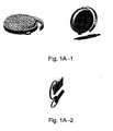
- FIGS 1A-1D are exemplary drawings of various headsets. Such headsets may be designed to be used with a handheld device such as a mobile phone, MP3 player, or other music player or device. In one embodiment, the headset is designed such that the positions that the headset may rest on a level surface, such as a table, is different from the orientation of the headset when worn by a user. As can be seen on Figure 1A , the headset would have to rest on a sharp edge in order to be in the same position as on a user's head.
- Figure 1B illustrates one embodiment of a headset configuration which is an in-ear device that may be used to ensure that the orientation when worn is not duplicated when the headset is stored or carried.
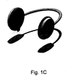
- Figure 1C illustrates one embodiment of a headset which is a headphone having a similar quality.
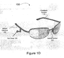
- Figure 1D illustrates one embodiment of a headset which is a pair of glasses incorporating an audio output.
- headset for the purposes of this patent encompasses all devices designed to be worn on the user's head, and designed to transmit sound to the user whether through an in-ear speaker, bone conduction, or any other means of audio output.
- a simple gravity sensor may be used to detect orientation (e.g. a suspended weight, which has the weight touching a contact, when the headset is in a particular orientation).
- an accelerometer may be used to determine orientation. The orientation may be determined based upon the rolling averages of accelerations.
- a dominant axis is assigned based upon the orientation. Determining an orientation of the electronic device may include identifying a gravitational influence. The axis with the largest absolute rolling average may be the axis most influenced by gravity, which may change over time (e.g. as the electronic device is rotated). Therefore, a new dominant axis may be assigned when the orientation of the electronic device and/or the inertial sensor(s) attached to or embedded in the electronic device changes.
- the actual axis with the largest absolute rolling average over the sample period is assigned as the dominant axis.
- the dominant axis does not correspond to one of the actual axes of the inertial sensor(s) in a current orientation, but rather to an axis that is defined as approximately aligned to gravity.
- the dominant axis corresponds to a virtual axis that is a component of a virtual coordinate system.
- a true gravity assessment such as by doing trigonometric calculations on the actual axes based on the gravitational influence is performed to determine orientation.
- FIG. 2 is a block diagram of one embodiment of a headset control system. Note that the other aspects of the headset, e.g. transmission, voice control, any other features are not shown in this figure for simplicity.
- the system 200 includes sensor logic 210.
- the sensor logic 210 includes an orientation sensor 215.
- the orientation sensor 215 determines the orientation of the headset in space. In one embodiment, this is used for headsets configured to ensure that the "worn" orientation is not reproduced in other locations.
- the sensor logic 210 includes an accelerometer 220.
- the accelerometer 220 determines orientation by detecting gravity, as noted above.
- the accelerometer 220 determines whether a headset is being worn based on a motion signature. Generally speaking, people do not hold their heads perfectly steady. Even while standing still, minute motions are made naturally. The accelerometer 220 in the headset can detect these motions, and utilize that data to determine that the headset is being worn. There are motion signatures 225 stored, to which the motions detected by the accelerometer are compared. For example, the motion signature of placing the headset on the ear and removing the headset from the ear is utilized to detect when the headset is being worn. If it has been placed on the ear, but not removed, the headset is almost certainly being worn.
- the accelerometer 220 is also used to detect commands indicated by motions such as taps and shakes.
- command mapper 230 may be used to identify commands based on accelerometer data.
- accelerometer 220 includes a buffer (not shown), to buffer the accelerometer data temporarily.
- a temperature sensor 235 may be used to detect that the headset is being worn. The temperature sensor 235 would detect the user's body temperature, which is unlikely to be achieved in other environments, e.g. on a desk, in a purse, etc. In one embodiment, the output temperature sensor 235 may also be used for detecting health issues. In one embodiment, the temperature sensor 235 may also be used to provide a temperature-based adjustment to a step counter 240. In one embodiment, the temperature sensor 235 may include two sensors, an ambient sensor (e.g. external to the user) and a body sensor (e.g. the user's body temperature). With two sensors, the system can distinguish between being in a hot car and being worn, based on a difference in ambient and body temperatures. In one embodiment, the temperature difference may also be used to adjust other measurements, as will be described below.
- a heart rate sensor 245 may be included in the system as well.
- the heart rate sensor 245 may be incorporated into an ear clip which is part of the headset.
- the signal from an infrared light transmitted through earlobe would then be used to detect the heart rate in one embodiment.
- reflected infrared light somewhere else on the head where there is a high density of capillaries may be used.
- the heart rate detection may be used to determine whether the headset is being worn.
- the heart rate data may also be used to provide an exertion based adjustment to the sports solution 240.
- one or more of the sensors 210 may be present in a headset, and the sensors can be used to determine with some certainty whether a headset is being worn by a user.
- the system includes a sports solution 240.
- the sports solution 240 is used to calculate activity information which may include speed, distance, cadence, steps and data via the headset. In one embodiment, temperature or heart rate data may also be provided to the sports solution 240.
- the sports solution 240 can adjust the calories burned, or the cadences, based on such data, as appropriate.
- a step counting algorithm that may be used by the system is described in U.S. Patent Publication No. US 2009-0043531 entitled "HUMAN ACTIVITY MONITORING DEVICE WITH DISTANCE CALCULATION.”
- the output of sports solution 240 may be provided to the user directly via audio feedback using training logic 290.
- the sports solution's data may be made available to the user via alternative connections, e.g. a web page or a home computer.
- the Sports solution tracks the user's steps taken throughout the day.
- This activity data and other sensor data may be sent to a remote server. It may be sent via SMS message through a wirelessly tethered mobile phone, or by alternative means.
- the collected data received from the headset may be stored in a central location, and made available to the user.
- U.S. Patent Publication No. US 2007-0024441 entitled "MONITOR, CONTROL, AND SHARE (MACS) SYSTEM".
- the headset further includes a button interface 295.
- Button interface along with speaker system enables a single button to provide control over the sports solution, and provide audio feedback to the user.
- Figure 6 is a flowchart of one embodiment of using the single button navigation structure.
- Figure 7 is an exemplary table that describes one embodiment of the command loops which can be used.
- the button interface provides the ability to utilize a looping menu system, enabling the user to perform complex selections with the single button.
- the system further includes configuration logic 250.
- Configuration logic 250 enables the system to change the settings/profiles based on detected information.
- configuration logic 250 enables the headset to change the headset configuration.
- configuration logic 250 enables the headset to send commands to a mobile device which is coupled to the headset, and change the configuration of the mobile device as well.
- configuration logic 250 includes a power logic 260.
- Power logic 260 enables the headset to be powered down, when the headset is not being worn, and automatically turned on when the headset is worn.
- headsets such as Bluetooth headsets are powered by batteries. The user is supposed to manually turn them off when he or she takes them off. This often does not happen, draining the batteries. Therefore, the power logic 260 powers down the transmission and other high powered elements of the headset when the headset is not being worn. Simply by monitoring the sensors 210, which require little power compared to maintaining a Bluetooth or similar network, the headset can be powered down and up, based on actual use.
- the power logic 260 gradually scales down sampling of the sensors, as time lapses.
- accelerometer data may be sampled every 10 milliseconds.
- the sampling rate may be decreased to every 40 milliseconds, and as time lapses the sampling rate may be decreased - gradually, stepwise, or in one step - to the lowest sampling rate.
- the lowest sampling rate is one sample per second.
- configuration logic 250 further includes profile adjustor 270.
- Profile adjustor 270 adjusts the headset and/or the related mobile device to a different profile.
- Device profiles include the format of how notifications are displayed (e.g. ringing on the headset, ringing a mobile device, ringing both, vibration, etc.)
- the profile adjustor 270 can adjust the notification profile to ring only in the headset (and not the phone), and vice versa if the phone is not being worn.
- Other profile adjustments may be implemented by the profile adjustor 270 in response to sensor input.
- the system further includes command logic 280.
- Command logic 280 utilizes data from the sensors 210 to execute commands.
- command logic 280 utilizes data from the accelerometer 220.
- command logic 280 interfaces with command store 285, which stores motion signatures for various commands.
- Such commands may include, for example "answer phone in response to detecting a tap-tap command if headset is on-ear,” "answer phone in response to detecting a shake-shake command if the headset is not on-ear” or activate headset when detecting that headset is picked up and placed on ear,” etc.
- the system further includes a user interface 290, which enables a user to adjust the settings.
- the user may adjust the profile options, commands, and mappings through user interface 290.
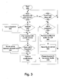
- FIG. 3 is a flowchart of one embodiment of the system.
- the process in one embodiment, is active whenever the handset is powered.
- the process determines whether the headset has been placed into the "worn" position.
- the worn position corresponds to whatever position the headset inhabits when it is in use. If the process determines that the headset has been placed in the worn position, the process continues to block 315.
- the process determines whether the headset is currently off. If so, at block 320, the headset is turned on In one embodiment, turning on the headset includes enabling any wireless communications, speakers, microphones and other aspects of a headset which would be utilized when the headset is in use. The process then continues to block 325. If the headset was not off, the process continues directly to block 325.
- the headset is paired to a mobile device, if this is appropriate. This is applicable only to wirelessly coupled headsets, as wired headsets need not be paired. If the headset is wireless, at block 325, whatever configurations need to be adjusted to couple the headset to the mobile device is performed. In one embodiment, the pairing may be done by utilizing a motion command.
- One embodiment of pairing in this manner is described in U.S. Patent No. 7,907,901 entitled “METHOD AND APPARATUS TO ENABLE PAIRING OF DEVICES".
- the process determines whether there is a call in progress on the mobile device. If so, at block 340, the call is routed to the headset, and answered. This enables a user to pick up a call on a headset simply by placing the headset on the ear. In one embodiment, this feature may be enabled and disabled by the user. The process then continues to block 345. If there is no call in progress, the process continues directly to block 345.
- the process performs any other configuration steps.
- the configuration may include setting the ringer to ring via the headset only, etc.
- the process then returns to block 310, to continue monitoring the status of the headset.
- the process determines whether the headset has been taken off. If so, the process continues to block 355. Otherwise, the process returns to block 310 to continue monitoring the status of the headset.
- the process determines whether there is a call in progress, if the mobile device is a telephone. If there is a call in progress, at block 360, the call is placed on hold, as a result of the headset being taken off. In another embodiment, the call may be routed to a speaker phone. In another embodiment, the call may be routed to a speaker phone, and the microphone may be muted. In one embodiment, the user may configure which of these options occurs. In one embodiment, the user may, while removing the headset, perform a motion command to select an option. In one embodiment, nothing further happens until the call is terminated. The device remains in this state, in one embodiment until the user performs another action. Therefore, the process returns to block 310, to monitor the headset. If there was no call in progress, as determined at block 360, the process continues to block 365.
- the process re-configures the device as if the headset were not connected. For example, it ensures that any notifications happen through the mobile device, not the headset.
- the headset is placed in suspend or low-power mode. In this mode, there is sufficient power maintained to monitor at least one sensor. However, other elements such as Bluetooth or other wireless connections are turned off. This extends the battery life of the device. The process then returns to block 310, to monitor for motion.
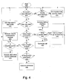
- Figure 4 is a flowchart of one embodiment of using command data for a headset.
- accelerometer data is continuously received in a buffer, and evaluated.
- the process starts at block 410.
- the process determines whether the data in the buffer corresponds to relevant accelerometer data, e.g. sufficient data for evaluation.
- Relevant accelerometer data is accelerometer data which may correspond to a command, step, or other monitored unit. If no accelerometer data was received, the process continues to block 415.
- the process determines whether a sufficient period of no motion has occurred. Humans are always moving, at least minor muscle tremors occur even while holding "perfectly still.” Therefore, a complete lack of motion indicates that the device is not being worn by a user. If a sufficient period of motionlessness has occurred - in one embodiment 5 seconds - the headset is turned off/put on standby. The process then ends at block 420. Note that the headset, in one embodiment, continues to monitor for accelerations, even while in standby mode.
- the process determines that the period of non-motion is below the threshold, the process returns to block 410, to continue monitoring the acceleration data.
- the process determines whether the accelerometer data corresponds to a step.
- a step is a unit of movement which is used to monitor a user's activity level. If so, at block 430, the step is added to the step buffer. The data corresponding to the step is then removed from the accelerometer buffer. The process then returns to block 410, to continue monitoring the accelerometer data.
- one phone command is a shake shake (e.g. a particular identified motion).
- shake shake in this case corresponds to sharp changes in direction (e.g. rapidly moving the device up-down-up-down).
- a shake is defined by an acceleration, a sharp change in direction, and another acceleration, for example rapidly moving the device up and then down.
- the shake shake command may be available when the headset is not worn.
- a phone command may be a tap-tap (e.g. two taps on the headset itself).
- any other defined set of motions may be substituted for the purposes of this discussion.
- the process determines whether there is an incoming call, a call in progress, or neither. If there is an incoming call, at block 445, the phone command picks up the call. In one embodiment, the phone command further routes the call to the headset. Since the user is utilizing the headset accelerometer command to pick up the call, it is assumed that the user will wish to utilize the headset for the call. In one embodiment, the user may choose to route the call to voicemail, instead of answering the call, by utilizing a different command. For example, tapping the device three times may be the "send to voicemail command.” For another example, taking the headset off may be a command to send the incoming call to voicemail.
- the phone command is used to terminate the call. If neither was true, in one embodiment the headset instructs the mobile device to display an interface at block 453.
- the interface may be a dialing interface. In one embodiment, the interface may be a speech recognition menu. The process then returns to block 410, to continue monitoring the accelerometer data. If the data was not a phone command, the process continues to block 455.
- the process determines whether the acceleration data corresponds to volume control.
- Controlling volume in one embodiment, is based on a motion signature.
- the user may define an appropriate motion signature.
- volume control in one embodiment may comprise a tap-tap (e.g. two short taps on the headset while it is worn.) If the acceleration data was a volume control, the process continues to block 460.
- the process determines whether the headset is being properly worn. In one embodiment, "properly worn" indicates that the headset is worn in a way that the user can utilize the speaker in the headset if one is present. If the headset is properly worn, then the volume control is adjusted in response to the volume control command, at block 465.
- the volume control is a cycle (e.g. each tap-tap command increases the volume until a maximum volume is reached, and subsequent tap-taps decrease the volume).
- Alternative methods of volume control may be used. For example, a tap-tap on one side of the device may indicate that the volume should be increased, while a tap on the other side of the device may indicate that the volume should be decreased. If the headset is not worn, an alternative volume command is executed, at block 470.
- the process determines whether the accelerometer data corresponds to any other command that is recognized. If so, that command is executed, at block 485.
- the command execution may vary by the position of the headset. In one embodiment, a different command may be associated with the same accelerometer data when the headset is worn v. when the headset is in a rest position. The process then returns to block 410, to continue monitoring the accelerometer data.
- Figure 5 is a flowchart of one embodiment of using other sensor data with a headset.
- the headset can be used as a step counter. Step counting is useful for determining a user's activity level.
- the step counting mechanism is independent of the headset's location, e.g. it works whether the headset is worn, or carried in a pocket, bag, backpack, purse, or elsewhere on the user.
- the process accumulates accelerometer data.
- the process determines whether a potential step has been detected. In one embodiment, if a potential step is detected, the process continues to block 525. Otherwise, the process returns to block 510, to continue accumulating accelerometer data.
- the process determines whether there is an established cadence for the steps.
- people walk at a particular cadence, and their cadence does not change unless circumstances change, e.g. the terrain, environment, or goals change.
- the process determines whether the potential steps fit within the cadence. If so, at block 535, they are added to the step buffer. The process then continues to block 540.
- the audio output is adapted - if it is not already so -- to the user's cadence/steps. That is, based on the cadence, the system estimates a noise level, and adjusts audio output. Generally, when a user is running the ambient noise level is quite a lot higher than during a stroll. Therefore, in one embodiment, the audio output - whether of a mobile telephone, a mobile music player, or another device - is adjusted based on the user's cadence.
- the system may further include a training aspect.
- the training aspect provides audio feedback to the user.
- the cadence-adjustment for the audio feedback ensures that the feedback is appropriate to the cadence.
- a user running at a steady high cadence, as exercise, is likely interested in different data than a user who is taking a leisurely stroll.
- the headset measures that the user is walking, it provides walking related feedback focused on number of steps, aerobic steps, distance and calories.
- feedback is on running parameters such as distance covered, pace, and speed.
- the feedback itself, and the particular types of feedback at various cadences are configurable by the user.
- the process determines whether there are other sensors whose data should be integrated with the accelerometer data. If so, the process continues to block 550. Otherwise, the process returns to block 510, to continue monitoring the accelerometer data.
- the process compares sensor data with expected data.
- the expected data is based on immediate past data - e.g. the last set of readings for this user. In one embodiment, expected data may also utilize statistical data regarding this user, or equivalent users.
- the process determines whether the difference is an actual difference or a glitch or spike that should be ignored, or a potential problem.
- the ambient lighting and user's sweat may affect the readings from the sensor.
- the accelerometer data can adjust for such. For example, if a user is running along at a constant cadence and relatively constant heart rate, if there is a sudden spike in the heart rate, there should be a corresponding change in cadence to reflect this change in heart rate. If cadence has not changed in either direction, then this anomaly in the heart rate can be removed.
- one of the sensors can be used to measure changes in elevation. Knowing elevation changes can be again used to correct the sensor data. For example, if heart rate increases, and the pressure sensor shows that the user is climbing in elevation, and cadence changes slightly, then the system can determine that the user is running up a hill. If cadence is unchanged, elevation is unchanged, but heart rate spikes up or down, again this can be corrected, if it is the result of interfering factors such as user's sweat or changes in ambient lighting effecting the reading of an ear clip heart rate monitor.
- the process determines that the change is a glitch and is not a real change in the parameter being measured, the data is corrected at block 565.
- the data is stored. In one embodiment, the full data is stored, but the glitch is labeled. In one embodiment, by making this correction, the user is reassured that the sensor error is not an indicator of a health problem. In another embodiment, the glitch is not displayed. In one embodiment, the glitch data may be displayed upon specific request. In one embodiment, the glitch data may be collected for the purposes of evaluating sensor quality, accuracy, or usefulness. In another embodiment, the glitch data is not stored at all. The process then returns to block 510, to continue collecting data.
- the process utilizes the sensor data to determine whether there are any abnormalities in the accelerometer readings. This parallels the discussion about correcting sensor glitches based on accelerometer data. If no corrections are needed, at block 580, the process starts a new step buffer. This new step buffer will be maintained until a new cadence is established. If there are abnormalities, at block 575, the process adjusts the cadence data based on the sensor information at block 585. The process then returns to block 530, and the step data is then either added to the existing step count, or to the new step buffer, depending on whether the adjusted cadence is still different from a current cadence.
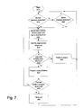
- Figure 7 is a flowchart of one embodiment of using a single button interface.
- the process starts at block 610. In one embodiment, the process starts when the device is active, but no buttons have been pressed.
- the process determines whether any buttons presses have been detected.
- multiple button presses in rapid sequence may comprise a single command. Therefore, prior to evaluating the button press data the device ensures that the button presses are finished. If so, the process continues to block 620. Otherwise, the process continues to block 660.
- the process determines the current state of the device, and the current location in the menu tree.
- the appropriate response is identified.
- the appropriate action may be a change in state (e.g. turning on or off some feature), a change in feature (e.g. turn up or down the volume), or presenting another menu option.
- the process determines whether the menu choice is an action, or the presentation of additional menu choices. If the response was to perform an action, at block 650 the action is performed. The process then returns to block 615 to monitor for further button presses.
- menu choices are presented by verbally listing the options to the user.
- the process continues to block 670, to detect a subsequent button presses. At block 670, a subsequent button press is detected. The process then continues to block 620, to act on the subsequent button press.
- the process times out after a while, at block 680. After the process times out, it returns to block 615, to determine whether any button presses have been detected.
- the process determines whether there has been any state change detected that may trigger an action in the menu. For example, in one embodiment, a user beginning or ending a workout may trigger an action. In one embodiment, the sensor data is used to detect the state changes.
- the process returns to block 615, to continue monitoring for button selections. If a state change is detected, the process continues to block 620, to detect the new state of the device, and the current location in the menu tree. In this way, the user can control the device utilizing only a single button.
- the headset may include a sports/lifestyle button.
- Figure 6 is a table of one embodiment of using this feature.
- the sports/lifestyle button provides a single button user interface. In one embodiment, this works for a single ear solution as well as a stereo headset.
- the button enables a user to navigate through various options, without having to take off the headset, and without requiring a visual feedback mechanism (e.g. a screen).
- a visual feedback mechanism e.g. a screen.
- the user need not grope for the correct button, and the interface can be easily implemented on a device with extremely limited real-estate such as a headset.
- Figure 6 illustrates an exemplary navigation using a single button, for a lifestyle/sports application. As can be seen, depending on the starting condition, the result of each button press differs.
- audio feedback may be used, to indicate what command was received.
- the feedback may be via vibration, or audio data provided via bone conduction rather than a speaker.
- the user can start, pause, and stop a workout program.
- a musical accompaniment may play.
- Figure 6 shows an exemplary table of actions in response to various types of activations of a single button.
- One of skill in the art would understand that this would apply to other types of applications, for example to navigation with a music player, a mobile phone application, etc.
- Figure 8 is a flowchart of one embodiment of accelerometer based commands, and appropriate feedback.
- the process starts at block 810.
- the system continuously monitors for motion commands.
- a motion command in one embodiment may be a shake shake command.
- a shake shake command is a rapid up-down-up-down movement of a device. Of course, this command can only be received when the device is not being born.
- the motion command may be a tap tap command.
- a tap tap command is two taps in rapid sequence on the device itself. This command can be most easily received when the device is worn.
- the associated action is identified if possible. If the associated action cannot be identified, at block 840, the process informs the user of this failure, at block 850. If the action is successfully identified, at block 860 the action is taken.
- the associated action depends on a state of the device. For example, if the device is a music player that also has a mobile phone aspect, a tap tap command may mean "answer the phone" if there is a call in progress, or "advance to the next song" if there is no call, and the music is playing.
- the user may program the commands available for each type of motion command. In one embodiment, a set of default commands may be pre-programmed.
- the process determines whether feedback should be provided for the command. If feedback should be provided, the process provides the appropriate feedback at block 880.
- Feedback for the command may include spoken audio feedback (e.g. "exercise program initiated"), tone audio feedback (e.g. a beep), or feedback provided through bone conduction for a headset that is being worn. Bone conduction is the conduction of sound to the inner ear through the bones of the skull. The process then returns to block 810 to continue monitoring for commands.
- FIG. 9 illustrates a block diagram of one embodiment of a computer system which may be used with the present invention. It will be apparent to those of ordinary skill in the art, however that other alternative systems of various system architectures may also be used.
- the computer system may include a bus or other internal communication means 915 for communicating information, and a processor 910 coupled to the bus 915 for processing information.
- the system further comprises a random access memory (RAM) or other volatile storage device 950 (referred to as memory), coupled to bus 915 for storing information and instructions to be executed by processor 910.
- Main memory 950 also may be used for storing temporary variables or other intermediate information during execution of instructions by processor 910.
- the system also comprises a read only memory (ROM) and/or static storage device 920 coupled to bus 915 for storing static information and instructions for processor 910, and a data storage device 925 such as a flash memory, magnetic disk, optical disk and its corresponding disk drive.
- ROM read only memory
- data storage device 925 such as a flash memory, magnetic disk, optical disk and its corresponding disk drive.
- Data storage device 925 is coupled to bus 915 for storing information and instructions.
- the system may include various input/output devices, such as a screen, audio output, keyboard, button, mouse, etc. These I/O devices may also be coupled to bus 915 through bus 965 for communicating information and command selections to processor 910.
- Another device which may optionally be coupled to computer system 900, is a communication device 990 for accessing other nodes of a distributed system via a network.
- the communication device 990 may include any of a number of commercially available networking peripheral devices such as those used for coupling to an Ethernet, token ring, Internet, or wide area network.
- the communication device 990 may further be a null-modem connection, a wireless connection mechanism, or any other mechanism that provides connectivity between the computer system 900 and the outside world.
- control logic or software implementing the present invention can be stored in main memory 950, mass storage device 925, or other storage medium locally or remotely accessible to processor 910.
- the present invention may also be embodied in a handheld or portable device containing a subset of the computer hardware components described above.
- the handheld device may be configured to contain only the bus 915, the processor 910, and memory 950 and/or 925.
- the present invention may also be embodied in a special purpose appliance including a subset of the computer hardware components described above.
- the appliance may include a processor 910, a data storage device 925, a bus 915, and memory 950, and only rudimentary communications mechanisms, such as a small touch-screen that permits the user to communicate in a basic manner with the device.
- the more special-purpose the device is the fewer of the elements need be present for the device to function.
- communications with the user may be through a touch-based screen, or similar mechanism.
- a machine-readable medium includes any mechanism for storing or transmitting information in a form readable by a machine (e.g. a computer).
- a machine readable medium includes read-only memory (ROM), random access memory (RAM), magnetic disk storage media, optical storage media, flash memory devices, electrical, optical, acoustical or other forms of propagated signals (e.g. carrier waves, infrared signals, digital signals, etc.).
Description
- The present invention relates to headsets, and more particularly to headsets using one or more sensors within the headset for improved operation.
- As portable devices are becoming more common, headsets are proliferating. Headsets include the Bluetooth headsets or plug-in headsets often used with mobile phones, headphones used with music players or other listening devices. Headsets may also be used with stationary devices such as landline telephones, computers, stereos, etc.
- While many older headsets are unpowered devices, simply using wires to lead the sound to the user's ears, newer headsets are powered, and often include some processing power. In particular, headsets that have wireless connectivity are battery powered. Some wired headsets also are powered to provide noise cancellation or other features.
- In
US 2007/0281762 there is described a communication accessory that includes at least a first sensor that indicates whether the communication accessory is being worn by a user. The communication accessory also can include a communications adapter that communicates a signal which indicates to a communication device whether the communication accessory is being worn. The communication accessory further can include a controller that processes at least one signal generated by the first sensor to determine whether the communication accessory is being worn by the user. The controller can enter the communication accessory into a standby state in response to the first sensor indicating that the communication accessory is not being worn. The controller can take the communication accessory out of the standby state in response to the first sensor indicating that the communication accessory is being worn. - By contrast, in
US 2006/0140422 there is described an apparatus and method for receiving inputs from a user. The inputs from the user may be head gestures and/or speech of the user. The head gestures refer to movements of the head of the user. The apparatus includes an accelerometer for receiving inputs from the user. The inputs are in form of nasal bone vibrations of the user, which are caused by the head gestures and/or speech of the user. The accelerometer further generates signals corresponding to the inputs received from the user. - According to the present invention there is provided a headset having the features of
claim 1. - The headset includes at least one sensor. The sensor is used in the headset to improve function.
- The present invention is illustrated by way of example, and not by way of limitation, in the figures of the accompanying drawings and in which like reference numerals refer to similar elements and in which:
-
Figures 1 A-D are exemplary forms of headsets. -
Figure 2 is a block diagram of one embodiment of a headset. -
Figure 3 is a flowchart of one embodiment of utilizing sensor data with a headset. -
Figure 4 is a flowchart of one embodiment of using command data for a headset. -
Figure 5 is a flowchart of one embodiment of using other sensor data with a headset. -
Figure 6 is a table of one example of using a sports/lifestyle application with a single button user interface. -
Figure 7 is a flowchart of one embodiment of using a single button user interface. -
Figure 8 is a flowchart of one embodiment of using accelerometer based commands. -
Figure 9 is a block diagram of one embodiment of a computer system which may be used with the present invention. - The method and apparatus described is a headset including at least one sensor. The headset, in one embodiment, includes a motion sensor to detect the motion and orientation of the headset. If the headset is in the orientation indicating that it is being worn by a user and exhibiting a motion signature indicative that it is being worn by a user, then certain configurations may be enabled, and the headset may be utilized in certain ways. In one embodiment, an accelerometer may be used to detect position. In one embodiment, an accelerometer may be used to detect minor motions characteristic of being positioned on a user's ear or head, indicating that the headset is being worn. In one embodiment, a temperature, heart rate, or other sensor may be integrated into the headset.
- The following detailed description of embodiments of the invention makes reference to the accompanying drawings in which like references indicate similar elements, showing by way of illustration specific embodiments of practicing the invention. Description of these embodiments is in sufficient detail to enable those skilled in the art to practice the invention. One skilled in the art understands that other embodiments may be utilized and that logical, mechanical, electrical, functional and other changes may be made without departing from the scope of the present invention. The following detailed description is, therefore, not to be taken in a limiting sense, and the scope of the present invention is defined only by the appended claims.
-
Figures 1A-1D are exemplary drawings of various headsets. Such headsets may be designed to be used with a handheld device such as a mobile phone, MP3 player, or other music player or device. In one embodiment, the headset is designed such that the positions that the headset may rest on a level surface, such as a table, is different from the orientation of the headset when worn by a user. As can be seen onFigure 1A , the headset would have to rest on a sharp edge in order to be in the same position as on a user's head. Similarly,Figure 1B illustrates one embodiment of a headset configuration which is an in-ear device that may be used to ensure that the orientation when worn is not duplicated when the headset is stored or carried.Figure 1C illustrates one embodiment of a headset which is a headphone having a similar quality.Figure 1D illustrates one embodiment of a headset which is a pair of glasses incorporating an audio output. - Note that the term headset for the purposes of this patent encompasses all devices designed to be worn on the user's head, and designed to transmit sound to the user whether through an in-ear speaker, bone conduction, or any other means of audio output.
- In one embodiment, a simple gravity sensor may be used to detect orientation (e.g. a suspended weight, which has the weight touching a contact, when the headset is in a particular orientation). In one embodiment, an accelerometer may be used to determine orientation. The orientation may be determined based upon the rolling averages of accelerations. In one embodiment, once the orientation is determined, a dominant axis is assigned based upon the orientation. Determining an orientation of the electronic device may include identifying a gravitational influence. The axis with the largest absolute rolling average may be the axis most influenced by gravity, which may change over time (e.g. as the electronic device is rotated). Therefore, a new dominant axis may be assigned when the orientation of the electronic device and/or the inertial sensor(s) attached to or embedded in the electronic device changes.
- In one embodiment, the actual axis with the largest absolute rolling average over the sample period is assigned as the dominant axis. In alternative embodiments, the dominant axis does not correspond to one of the actual axes of the inertial sensor(s) in a current orientation, but rather to an axis that is defined as approximately aligned to gravity. In one embodiment, the dominant axis corresponds to a virtual axis that is a component of a virtual coordinate system. In one embodiment, a true gravity assessment, such as by doing trigonometric calculations on the actual axes based on the gravitational influence is performed to determine orientation.
- By ensuring that the "worn" orientation is not likely when the device is elsewhere, a simple identification of the worn orientation is sufficient to identify that the headset is being worn.
-
Figure 2 is a block diagram of one embodiment of a headset control system. Note that the other aspects of the headset, e.g. transmission, voice control, any other features are not shown in this figure for simplicity. - The
system 200 includes sensor logic 210. In one embodiment, the sensor logic 210 includes anorientation sensor 215. Theorientation sensor 215 determines the orientation of the headset in space. In one embodiment, this is used for headsets configured to ensure that the "worn" orientation is not reproduced in other locations. - In one embodiment, the sensor logic 210 includes an
accelerometer 220. Theaccelerometer 220 in one embodiment, determines orientation by detecting gravity, as noted above. In one embodiment, theaccelerometer 220 determines whether a headset is being worn based on a motion signature. Generally speaking, people do not hold their heads perfectly steady. Even while standing still, minute motions are made naturally. Theaccelerometer 220 in the headset can detect these motions, and utilize that data to determine that the headset is being worn. There aremotion signatures 225 stored, to which the motions detected by the accelerometer are compared. For example, the motion signature of placing the headset on the ear and removing the headset from the ear is utilized to detect when the headset is being worn. If it has been placed on the ear, but not removed, the headset is almost certainly being worn. - In one embodiment, the
accelerometer 220 is also used to detect commands indicated by motions such as taps and shakes. In one embodiment,command mapper 230 may be used to identify commands based on accelerometer data. In one embodiment,accelerometer 220 includes a buffer (not shown), to buffer the accelerometer data temporarily. - In one embodiment, a
temperature sensor 235 may be used to detect that the headset is being worn. Thetemperature sensor 235 would detect the user's body temperature, which is unlikely to be achieved in other environments, e.g. on a desk, in a purse, etc. In one embodiment, theoutput temperature sensor 235 may also be used for detecting health issues. In one embodiment, thetemperature sensor 235 may also be used to provide a temperature-based adjustment to astep counter 240. In one embodiment, thetemperature sensor 235 may include two sensors, an ambient sensor (e.g. external to the user) and a body sensor (e.g. the user's body temperature). With two sensors, the system can distinguish between being in a hot car and being worn, based on a difference in ambient and body temperatures. In one embodiment, the temperature difference may also be used to adjust other measurements, as will be described below. - In one embodiment, a
heart rate sensor 245 may be included in the system as well. In one embodiment theheart rate sensor 245 may be incorporated into an ear clip which is part of the headset. The signal from an infrared light transmitted through earlobe would then be used to detect the heart rate in one embodiment. In another embodiment, reflected infrared light somewhere else on the head where there is a high density of capillaries may be used. The heart rate detection may be used to determine whether the headset is being worn. In one embodiment, the heart rate data may also be used to provide an exertion based adjustment to thesports solution 240. - In one embodiment, one or more of the sensors 210 may be present in a headset, and the sensors can be used to determine with some certainty whether a headset is being worn by a user.
- In one embodiment, as noted above, the system includes a
sports solution 240. Thesports solution 240 is used to calculate activity information which may include speed, distance, cadence, steps and data via the headset. In one embodiment, temperature or heart rate data may also be provided to thesports solution 240. Thesports solution 240 can adjust the calories burned, or the cadences, based on such data, as appropriate. One embodiment of a step counting algorithm that may be used by the system is described in U.S. Patent Publication No.US 2009-0043531 entitled "HUMAN ACTIVITY MONITORING DEVICE WITH DISTANCE CALCULATION." In one embodiment, the output ofsports solution 240 may be provided to the user directly via audio feedback usingtraining logic 290. In one embodiment, the sports solution's data may be made available to the user via alternative connections, e.g. a web page or a home computer. In one embodiment, the Sports solution tracks the user's steps taken throughout the day. This activity data and other sensor data may be sent to a remote server. It may be sent via SMS message through a wirelessly tethered mobile phone, or by alternative means. In one embodiment, the collected data received from the headset may be stored in a central location, and made available to the user. One example of such a system is described in U.S. Patent Publication No.US 2007-0024441 , entitled "MONITOR, CONTROL, AND SHARE (MACS) SYSTEM". - In one embodiment, the headset further includes a
button interface 295. Button interface along with speaker system enables a single button to provide control over the sports solution, and provide audio feedback to the user.Figure 6 is a flowchart of one embodiment of using the single button navigation structure.Figure 7 is an exemplary table that describes one embodiment of the command loops which can be used. - In one embodiment, the button interface provides the ability to utilize a looping menu system, enabling the user to perform complex selections with the single button.
- In one embodiment, the system further includes configuration logic 250. Configuration logic 250 enables the system to change the settings/profiles based on detected information. In one embodiment, configuration logic 250 enables the headset to change the headset configuration. In one embodiment, configuration logic 250 enables the headset to send commands to a mobile device which is coupled to the headset, and change the configuration of the mobile device as well.
- In one embodiment, configuration logic 250 includes a
power logic 260.Power logic 260 enables the headset to be powered down, when the headset is not being worn, and automatically turned on when the headset is worn. Generally speaking headsets such as Bluetooth headsets are powered by batteries. The user is supposed to manually turn them off when he or she takes them off. This often does not happen, draining the batteries. Therefore, thepower logic 260 powers down the transmission and other high powered elements of the headset when the headset is not being worn. Simply by monitoring the sensors 210, which require little power compared to maintaining a Bluetooth or similar network, the headset can be powered down and up, based on actual use. In one embodiment, thepower logic 260 gradually scales down sampling of the sensors, as time lapses. For example, while in use accelerometer data may be sampled every 10 milliseconds. When lack of activity is initially detected, the sampling rate may be decreased to every 40 milliseconds, and as time lapses the sampling rate may be decreased - gradually, stepwise, or in one step - to the lowest sampling rate. In one embodiment, the lowest sampling rate is one sample per second. - In one embodiment, configuration logic 250 further includes
profile adjustor 270.Profile adjustor 270 adjusts the headset and/or the related mobile device to a different profile. Device profiles include the format of how notifications are displayed (e.g. ringing on the headset, ringing a mobile device, ringing both, vibration, etc.) When the system detects that the headset is worn, theprofile adjustor 270 can adjust the notification profile to ring only in the headset (and not the phone), and vice versa if the phone is not being worn. Other profile adjustments may be implemented by theprofile adjustor 270 in response to sensor input. - In one embodiment, the system further includes
command logic 280.Command logic 280 utilizes data from the sensors 210 to execute commands. In one embodiment,command logic 280 utilizes data from theaccelerometer 220. In one embodiment,command logic 280 interfaces withcommand store 285, which stores motion signatures for various commands. Such commands may include, for example "answer phone in response to detecting a tap-tap command if headset is on-ear," "answer phone in response to detecting a shake-shake command if the headset is not on-ear" or activate headset when detecting that headset is picked up and placed on ear," etc. - In one embodiment, the system further includes a
user interface 290, which enables a user to adjust the settings. In one embodiment, the user may adjust the profile options, commands, and mappings throughuser interface 290. -
Figure 3 is a flowchart of one embodiment of the system. The process, in one embodiment, is active whenever the handset is powered. - At block 310, the process determines whether the headset has been placed into the "worn" position. The worn position corresponds to whatever position the headset inhabits when it is in use. If the process determines that the headset has been placed in the worn position, the process continues to block 315.
- At
block 315, the process determines whether the headset is currently off. If so, atblock 320, the headset is turned on In one embodiment, turning on the headset includes enabling any wireless communications, speakers, microphones and other aspects of a headset which would be utilized when the headset is in use. The process then continues to block 325. If the headset was not off, the process continues directly to block 325. - At
block 325, the headset is paired to a mobile device, if this is appropriate. This is applicable only to wirelessly coupled headsets, as wired headsets need not be paired. If the headset is wireless, atblock 325, whatever configurations need to be adjusted to couple the headset to the mobile device is performed. In one embodiment, the pairing may be done by utilizing a motion command. One embodiment of pairing in this manner is described inU.S. Patent No. 7,907,901 entitled "METHOD AND APPARATUS TO ENABLE PAIRING OF DEVICES". - At
block 335, the process determines whether there is a call in progress on the mobile device. If so, atblock 340, the call is routed to the headset, and answered. This enables a user to pick up a call on a headset simply by placing the headset on the ear. In one embodiment, this feature may be enabled and disabled by the user. The process then continues to block 345. If there is no call in progress, the process continues directly to block 345. - At block 345, the process performs any other configuration steps. For example, in a mobile device such as a mobile phone, the configuration may include setting the ringer to ring via the headset only, etc.
- The process then returns to block 310, to continue monitoring the status of the headset.
- If at block 310 the process determined that the headset had not been put on, the process continues to block 350.
- At block 350, the process determines whether the headset has been taken off. If so, the process continues to block 355. Otherwise, the process returns to block 310 to continue monitoring the status of the headset.
- At
block 355, the process determines whether there is a call in progress, if the mobile device is a telephone. If there is a call in progress, at block 360, the call is placed on hold, as a result of the headset being taken off. In another embodiment, the call may be routed to a speaker phone. In another embodiment, the call may be routed to a speaker phone, and the microphone may be muted. In one embodiment, the user may configure which of these options occurs. In one embodiment, the user may, while removing the headset, perform a motion command to select an option. In one embodiment, nothing further happens until the call is terminated. The device remains in this state, in one embodiment until the user performs another action. Therefore, the process returns to block 310, to monitor the headset. If there was no call in progress, as determined at block 360, the process continues to block 365. - At block 365, the process re-configures the device as if the headset were not connected. For example, it ensures that any notifications happen through the mobile device, not the headset.
- At
block 370, the headset is placed in suspend or low-power mode. In this mode, there is sufficient power maintained to monitor at least one sensor. However, other elements such as Bluetooth or other wireless connections are turned off. This extends the battery life of the device. The process then returns to block 310, to monitor for motion. -
Figure 4 is a flowchart of one embodiment of using command data for a headset. In one embodiment, accelerometer data is continuously received in a buffer, and evaluated. - The process starts at
block 410. Atblock 410, the process determines whether the data in the buffer corresponds to relevant accelerometer data, e.g. sufficient data for evaluation. Relevant accelerometer data is accelerometer data which may correspond to a command, step, or other monitored unit. If no accelerometer data was received, the process continues to block 415. Atblock 415, the process determines whether a sufficient period of no motion has occurred. Humans are always moving, at least minor muscle tremors occur even while holding "perfectly still." Therefore, a complete lack of motion indicates that the device is not being worn by a user. If a sufficient period of motionlessness has occurred - in oneembodiment 5 seconds - the headset is turned off/put on standby. The process then ends at block 420. Note that the headset, in one embodiment, continues to monitor for accelerations, even while in standby mode. - If, at
block 415, the process determines that the period of non-motion is below the threshold, the process returns to block 410, to continue monitoring the acceleration data. - If, at
block 410, the process determined that relevant accelerometer data had been received, the process continues to block 425. - At
block 425, the process determines whether the accelerometer data corresponds to a step. A step is a unit of movement which is used to monitor a user's activity level. If so, atblock 430, the step is added to the step buffer. The data corresponding to the step is then removed from the accelerometer buffer. The process then returns to block 410, to continue monitoring the accelerometer data. - If, at
block 425, it was determined that the data did not correspond to a step, the process continues to block 435. - At
block 435, the process determines whether the acceleration was a phone command. In one embodiment, one phone command is a shake shake (e.g. a particular identified motion). Note that shake shake in this case corresponds to sharp changes in direction (e.g. rapidly moving the device up-down-up-down). In one embodiment, a shake is defined by an acceleration, a sharp change in direction, and another acceleration, for example rapidly moving the device up and then down. Note that while shake shake is the motion command described, alternative commands may be defined as well. In one embodiment, the shake shake command may be available when the headset is not worn. In one embodiment, when the headset is worn, a phone command may be a tap-tap (e.g. two taps on the headset itself). However, any other defined set of motions may be substituted for the purposes of this discussion. - If the acceleration was identified as a phone command, at
block 440, the process determines whether there is an incoming call, a call in progress, or neither. If there is an incoming call, atblock 445, the phone command picks up the call. In one embodiment, the phone command further routes the call to the headset. Since the user is utilizing the headset accelerometer command to pick up the call, it is assumed that the user will wish to utilize the headset for the call. In one embodiment, the user may choose to route the call to voicemail, instead of answering the call, by utilizing a different command. For example, tapping the device three times may be the "send to voicemail command." For another example, taking the headset off may be a command to send the incoming call to voicemail. - If there was a call in progress, at
block 450, in one embodiment the phone command is used to terminate the call. If neither was true, in one embodiment the headset instructs the mobile device to display an interface atblock 453. In one embodiment, the interface may be a dialing interface. In one embodiment, the interface may be a speech recognition menu. The process then returns to block 410, to continue monitoring the accelerometer data. If the data was not a phone command, the process continues to block 455. - At
block 455, the process determines whether the acceleration data corresponds to volume control. Controlling volume, in one embodiment, is based on a motion signature. In one embodiment, the user may define an appropriate motion signature. For example, volume control in one embodiment may comprise a tap-tap (e.g. two short taps on the headset while it is worn.) If the acceleration data was a volume control, the process continues to block 460. Atblock 460, the process determines whether the headset is being properly worn. In one embodiment, "properly worn" indicates that the headset is worn in a way that the user can utilize the speaker in the headset if one is present. If the headset is properly worn, then the volume control is adjusted in response to the volume control command, atblock 465. In one embodiment, the volume control is a cycle (e.g. each tap-tap command increases the volume until a maximum volume is reached, and subsequent tap-taps decrease the volume). Alternative methods of volume control may be used. For example, a tap-tap on one side of the device may indicate that the volume should be increased, while a tap on the other side of the device may indicate that the volume should be decreased. If the headset is not worn, an alternative volume command is executed, atblock 470. - At
block 480, the process determines whether the accelerometer data corresponds to any other command that is recognized. If so, that command is executed, atblock 485. The command execution may vary by the position of the headset. In one embodiment, a different command may be associated with the same accelerometer data when the headset is worn v. when the headset is in a rest position. The process then returns to block 410, to continue monitoring the accelerometer data. -
Figure 5 is a flowchart of one embodiment of using other sensor data with a headset. In one embodiment, the headset can be used as a step counter. Step counting is useful for determining a user's activity level. In one embodiment, the step counting mechanism is independent of the headset's location, e.g. it works whether the headset is worn, or carried in a pocket, bag, backpack, purse, or elsewhere on the user. - At
block 510, the process accumulates accelerometer data. At block 520, the process determines whether a potential step has been detected. In one embodiment, if a potential step is detected, the process continues to block 525. Otherwise, the process returns to block 510, to continue accumulating accelerometer data. - At
block 525, the process determines whether there is an established cadence for the steps. Generally speaking, people walk at a particular cadence, and their cadence does not change unless circumstances change, e.g. the terrain, environment, or goals change. - If there is an established cadence, at
block 530, the process determines whether the potential steps fit within the cadence. If so, atblock 535, they are added to the step buffer. The process then continues to block 540. - At
block 540, the audio output is adapted - if it is not already so -- to the user's cadence/steps. That is, based on the cadence, the system estimates a noise level, and adjusts audio output. Generally, when a user is running the ambient noise level is quite a lot higher than during a stroll. Therefore, in one embodiment, the audio output - whether of a mobile telephone, a mobile music player, or another device - is adjusted based on the user's cadence. - In one embodiment, the system may further include a training aspect. The training aspect provides audio feedback to the user. The cadence-adjustment for the audio feedback ensures that the feedback is appropriate to the cadence. A user running at a steady high cadence, as exercise, is likely interested in different data than a user who is taking a leisurely stroll. In one embodiment, if the headset measures that the user is walking, it provides walking related feedback focused on number of steps, aerobic steps, distance and calories. In one embodiment, if the headset detects a run, then feedback is on running parameters such as distance covered, pace, and speed. In one embodiment, the feedback itself, and the particular types of feedback at various cadences, are configurable by the user.
- At
block 545, the process determines whether there are other sensors whose data should be integrated with the accelerometer data. If so, the process continues to block 550. Otherwise, the process returns to block 510, to continue monitoring the accelerometer data. - At
block 550, the process compares sensor data with expected data. The expected data is based on immediate past data - e.g. the last set of readings for this user. In one embodiment, expected data may also utilize statistical data regarding this user, or equivalent users. - If there is a difference between the expected data and the actual sensor data, at block 560, the process determines whether the difference is an actual difference or a glitch or spike that should be ignored, or a potential problem.
- For example, when measuring heart rate through an earclip, the ambient lighting and user's sweat may affect the readings from the sensor. Using the accelerometer data can adjust for such. For example, if a user is running along at a constant cadence and relatively constant heart rate, if there is a sudden spike in the heart rate, there should be a corresponding change in cadence to reflect this change in heart rate. If cadence has not changed in either direction, then this anomaly in the heart rate can be removed.
- In another example, if one of the sensors is a pressure sensor, it can be used to measure changes in elevation. Knowing elevation changes can be again used to correct the sensor data. For example, if heart rate increases, and the pressure sensor shows that the user is climbing in elevation, and cadence changes slightly, then the system can determine that the user is running up a hill. If cadence is unchanged, elevation is unchanged, but heart rate spikes up or down, again this can be corrected, if it is the result of interfering factors such as user's sweat or changes in ambient lighting effecting the reading of an ear clip heart rate monitor.
- If, at block 560, the process determines that the change is a glitch and is not a real change in the parameter being measured, the data is corrected at block 565. At
block 570, the data is stored. In one embodiment, the full data is stored, but the glitch is labeled. In one embodiment, by making this correction, the user is reassured that the sensor error is not an indicator of a health problem. In another embodiment, the glitch is not displayed. In one embodiment, the glitch data may be displayed upon specific request. In one embodiment, the glitch data may be collected for the purposes of evaluating sensor quality, accuracy, or usefulness. In another embodiment, the glitch data is not stored at all. The process then returns to block 510, to continue collecting data. - If at
block 530, the process determined that the current steps were not within the cadence, the process continues to block 575. - At block 575, the process utilizes the sensor data to determine whether there are any abnormalities in the accelerometer readings. This parallels the discussion about correcting sensor glitches based on accelerometer data. If no corrections are needed, at
block 580, the process starts a new step buffer. This new step buffer will be maintained until a new cadence is established. If there are abnormalities, at block 575, the process adjusts the cadence data based on the sensor information at block 585. The process then returns to block 530, and the step data is then either added to the existing step count, or to the new step buffer, depending on whether the adjusted cadence is still different from a current cadence. - If at
block 525, no cadence was detected, the process continues to block 527. At block 527, a new cadence is established based on the new potential step data, and a new step buffer is initialized. The process then continues to block 535, where the potential step is added to the new step buffer. -
Figure 7 is a flowchart of one embodiment of using a single button interface. The process starts at block 610. In one embodiment, the process starts when the device is active, but no buttons have been pressed. - At
block 615, the process determines whether any buttons presses have been detected. In one embodiment, multiple button presses in rapid sequence may comprise a single command. Therefore, prior to evaluating the button press data the device ensures that the button presses are finished. If so, the process continues to block 620. Otherwise, the process continues to block 660. - At block 620, the process determines the current state of the device, and the current location in the menu tree. At
block 630, the appropriate response is identified. The appropriate action may be a change in state (e.g. turning on or off some feature), a change in feature (e.g. turn up or down the volume), or presenting another menu option. Atblock 640, the process determines whether the menu choice is an action, or the presentation of additional menu choices. If the response was to perform an action, atblock 650 the action is performed. The process then returns to block 615 to monitor for further button presses. - If the response is the presentation of further menu choices, the process continues to block 660. At
block 660, in one embodiment, menu choices are presented by verbally listing the options to the user. - If so, the process continues to block 670, to detect a subsequent button presses. At
block 670, a subsequent button press is detected. The process then continues to block 620, to act on the subsequent button press. - If there is no subsequent selection at
block 670, the process times out after a while, atblock 680. After the process times out, it returns to block 615, to determine whether any button presses have been detected. - If, at
block 615, no button presses are detected, the process continues to block 690. Atblock 690, the process determines whether there has been any state change detected that may trigger an action in the menu. For example, in one embodiment, a user beginning or ending a workout may trigger an action. In one embodiment, the sensor data is used to detect the state changes. - If no state change is detected, the process returns to block 615, to continue monitoring for button selections. If a state change is detected, the process continues to block 620, to detect the new state of the device, and the current location in the menu tree. In this way, the user can control the device utilizing only a single button.
- In one embodiment, the headset may include a sports/lifestyle button.
Figure 6 is a table of one embodiment of using this feature. - The sports/lifestyle button provides a single button user interface. In one embodiment, this works for a single ear solution as well as a stereo headset. The button enables a user to navigate through various options, without having to take off the headset, and without requiring a visual feedback mechanism (e.g. a screen). Furthermore, by only using a single button as the interface, the user need not grope for the correct button, and the interface can be easily implemented on a device with extremely limited real-estate such as a headset.
-
Figure 6 illustrates an exemplary navigation using a single button, for a lifestyle/sports application. As can be seen, depending on the starting condition, the result of each button press differs. In one embodiment, audio feedback may be used, to indicate what command was received. In another embodiment, the feedback may be via vibration, or audio data provided via bone conduction rather than a speaker. - In the table shown in
Figure 6 the user can start, pause, and stop a workout program. In one embodiment, while the workout program is active, a musical accompaniment may play. -
Figure 6 shows an exemplary table of actions in response to various types of activations of a single button. One of skill in the art would understand that this would apply to other types of applications, for example to navigation with a music player, a mobile phone application, etc. - In one embodiment, the user may utilize motions to communicate commands, instead of or in addition to using a button interface.
Figure 8 is a flowchart of one embodiment of accelerometer based commands, and appropriate feedback. - The process starts at
block 810. In one embodiment, the system continuously monitors for motion commands. - At block 820, the process determines whether a motion command has been received. A motion command, in one embodiment may be a shake shake command. A shake shake command is a rapid up-down-up-down movement of a device. Of course, this command can only be received when the device is not being born. In one embodiment, the motion command may be a tap tap command. A tap tap command is two taps in rapid sequence on the device itself. This command can be most easily received when the device is worn.
- If a motion command was received, at
block 830, the associated action is identified if possible. If the associated action cannot be identified, atblock 840, the process informs the user of this failure, atblock 850. If the action is successfully identified, atblock 860 the action is taken. In one embodiment, the associated action depends on a state of the device. For example, if the device is a music player that also has a mobile phone aspect, a tap tap command may mean "answer the phone" if there is a call in progress, or "advance to the next song" if there is no call, and the music is playing. In one embodiment, the user may program the commands available for each type of motion command. In one embodiment, a set of default commands may be pre-programmed. - At
block 870, the process determines whether feedback should be provided for the command. If feedback should be provided, the process provides the appropriate feedback atblock 880. Feedback for the command may include spoken audio feedback (e.g. "exercise program initiated"), tone audio feedback (e.g. a beep), or feedback provided through bone conduction for a headset that is being worn. Bone conduction is the conduction of sound to the inner ear through the bones of the skull. The process then returns to block 810 to continue monitoring for commands. -
Figure 9 illustrates a block diagram of one embodiment of a computer system which may be used with the present invention. It will be apparent to those of ordinary skill in the art, however that other alternative systems of various system architectures may also be used. The computer system may include a bus or other internal communication means 915 for communicating information, and aprocessor 910 coupled to thebus 915 for processing information. The system further comprises a random access memory (RAM) or other volatile storage device 950 (referred to as memory), coupled tobus 915 for storing information and instructions to be executed byprocessor 910.Main memory 950 also may be used for storing temporary variables or other intermediate information during execution of instructions byprocessor 910. In one embodiment, the system also comprises a read only memory (ROM) and/orstatic storage device 920 coupled tobus 915 for storing static information and instructions forprocessor 910, and adata storage device 925 such as a flash memory, magnetic disk, optical disk and its corresponding disk drive.Data storage device 925 is coupled tobus 915 for storing information and instructions. - The system may include various input/output devices, such as a screen, audio output, keyboard, button, mouse, etc. These I/O devices may also be coupled to
bus 915 throughbus 965 for communicating information and command selections toprocessor 910. Another device, which may optionally be coupled tocomputer system 900, is acommunication device 990 for accessing other nodes of a distributed system via a network. Thecommunication device 990 may include any of a number of commercially available networking peripheral devices such as those used for coupling to an Ethernet, token ring, Internet, or wide area network. Thecommunication device 990 may further be a null-modem connection, a wireless connection mechanism, or any other mechanism that provides connectivity between thecomputer system 900 and the outside world. Note that any or all of the components of this system and associated hardware may be used in various embodiments of the present invention. It will be appreciated by those of ordinary skill in the art that any configuration of the system may be used for various purposes according to the particular implementation. The control logic or software implementing the present invention can be stored inmain memory 950,mass storage device 925, or other storage medium locally or remotely accessible toprocessor 910. - It will be apparent to those of ordinary skill in the art that the system, method, and process described herein can be implemented as software stored in
main memory 950 or readonly memory 920 and executed byprocessor 910. This control logic or software may also be resident on an article of manufacture comprising a computer readable medium having computer readable program code embodied therein and being readable by themass storage device 925 and for causing theprocessor 910 to operate in accordance with the methods and teachings herein. - The present invention may also be embodied in a handheld or portable device containing a subset of the computer hardware components described above. For example, the handheld device may be configured to contain only the
bus 915, theprocessor 910, andmemory 950 and/or 925. The present invention may also be embodied in a special purpose appliance including a subset of the computer hardware components described above. For example, the appliance may include aprocessor 910, adata storage device 925, abus 915, andmemory 950, and only rudimentary communications mechanisms, such as a small touch-screen that permits the user to communicate in a basic manner with the device. In general, the more special-purpose the device is, the fewer of the elements need be present for the device to function. In some devices, communications with the user may be through a touch-based screen, or similar mechanism. - It will be appreciated by those of ordinary skill in the art that any configuration of the system may be used for various purposes according to the particular implementation. The control logic or software implementing the present invention can be stored on any machine-readable medium locally or remotely accessible to
processor 910. A machine-readable medium includes any mechanism for storing or transmitting information in a form readable by a machine (e.g. a computer). For example, a machine readable medium includes read-only memory (ROM), random access memory (RAM), magnetic disk storage media, optical storage media, flash memory devices, electrical, optical, acoustical or other forms of propagated signals (e.g. carrier waves, infrared signals, digital signals, etc.). - In the foregoing specification, the invention has been described with reference to specific exemplary embodiments thereof. It will, however, be evident that various modifications and changes may be made thereto without departing from the scope of the invention as set forth in the appended claims. The specification and drawings are, accordingly, to be regarded in an illustrative rather than a restrictive sense.
Claims (16)
- A headset comprising:a sensor (215,220) to obtain sensor data, the sensor data comprising a motion signature and orientation data, the orientation data being indicative of the orientation of the headset in space;a store (225) of motion signatures that includes a motion signature indicative of placement of the headset on the ear of a user and a motion signature indicative of removing the headset from the ear of a user, to which the motion signature obtained by the sensor (215,220) is compared to determine whether the headset is being worn by a user based on the obtained motion signature and orientation data; anda configuration logic (250) to configure the headset based on the sensor data and the determination of whether the headset is being worn.
- The headset of claim 1 further comprising a headset shape configured to define a first orientation associated with the headset being worn and a different orientation when the headset is placed somewhere else.
- The headset of claim 1 or claim 2, wherein the headset comprises a headset shape configured such that the positions in which the headset may rest on a level surface are different from the orientation of the headset when worn by a user.
- The headset of claim 1, wherein the headset comprises one of the following: an earbud, a headphone, a headset including a microphone and a speaker, and glasses (150) incorporating a speaker.
- The headset of claim 1, wherein the sensor (215,220) comprises an accelerometer (220) to determine a location of the headset, the location indicating whether the headset is being worn.
- The headset of claim 1, wherein the sensor (215,220) comprises an accelerometer (220) to detect a motion command, the motion command comprising a defined set of motions associated with a particular action, the headset further comprising a command store (285) which stores motion signatures for a plurality of commands, a command logic (280) that interfaces with the command store (285), and a command mapper (230) to identify a command associated with the motion command.
- The headset of claim 6, wherein the motion command comprises one or more of the following: a shake shake command when the headset is not being worn, a tap tap command when the headset is being worn, and a gesture comprising placing the headset on a user's head or removing the headset from the user's head.
- The headset of claim 6, further comprising:a feedback logic to provide feedback to the user regarding the identified command.
- The headset of claim 6 further comprising:a power logic (260) to automatically place the headset into stand-by mode when the headset is not moving, indicating that the headset is not being worn by a user.
- The headset of claim 1, further comprising:a profile adjustor (270) to adjust settings of the headset based on the sensor data.
- The headset of claim 10, wherein the profile adjustor (270) is adapted to adjust a setting of a mobile device linked to the headset based on the sensor data.
- The headset of claim 1, further comprising:a button logic (295) to enable control of a function of the headset utilizing a single button and audio feedback.
- A method comprising:obtaining sensor data from a headset sensor (215,220);determining a motion signature and an orientation of the headset in space based on the sensor data;comparing the motion signature with a store (225) of motion signatures that includes a motion signature indicative of placement of the headset on the ear of a user and a motion signature indicative of removing the headset from the ear of a user to determine whether the headset is being worn by a user based on the motion signature and the orientation of the headset; andconfiguring the headset based on the sensor data and whether the headset is being worn by a user.
- The method of claim 13, further comprising:identifying a motion command based on data from an accelerometer (220);identifying a command associated with the motion command; andexecuting the command.
- The method of claim 14, wherein the command comprises one or more of the following: altering a configuration of the headset, altering a configuration of a device coupled to the headset, altering an output characteristic of the headset, altering an output characteristic of the device coupled to the headset.
- The method of claim 13, further comprising:providing a single button interface (295) to enable a user to navigate through a set of menus utilizing a single button and audio feedback.
Applications Claiming Priority (2)
| Application Number | Priority Date | Filing Date | Title |
|---|---|---|---|
| US12/113,110 US8320578B2 (en) | 2008-04-30 | 2008-04-30 | Headset |
| PCT/US2009/042183 WO2009134940A1 (en) | 2008-04-30 | 2009-04-29 | An improved headset |
Publications (3)
| Publication Number | Publication Date |
|---|---|
| EP2277301A1 EP2277301A1 (en) | 2011-01-26 |
| EP2277301A4 EP2277301A4 (en) | 2013-01-02 |
| EP2277301B1 true EP2277301B1 (en) | 2015-09-09 |
Family
ID=41255404
Family Applications (1)
| Application Number | Title | Priority Date | Filing Date |
|---|---|---|---|
| EP09739742.6A Active EP2277301B1 (en) | 2008-04-30 | 2009-04-29 | An improved headset |
Country Status (4)
| Country | Link |
|---|---|
| US (1) | US8320578B2 (en) |
| EP (1) | EP2277301B1 (en) |
| JP (1) | JP5438759B2 (en) |
| WO (1) | WO2009134940A1 (en) |
Families Citing this family (115)
| Publication number | Priority date | Publication date | Assignee | Title |
|---|---|---|---|---|
| US7841967B1 (en) | 2006-04-26 | 2010-11-30 | Dp Technologies, Inc. | Method and apparatus for providing fitness coaching using a mobile device |
| US8902154B1 (en) | 2006-07-11 | 2014-12-02 | Dp Technologies, Inc. | Method and apparatus for utilizing motion user interface |
| US8620353B1 (en) | 2007-01-26 | 2013-12-31 | Dp Technologies, Inc. | Automatic sharing and publication of multimedia from a mobile device |
| US8949070B1 (en) | 2007-02-08 | 2015-02-03 | Dp Technologies, Inc. | Human activity monitoring device with activity identification |
| US8555282B1 (en) | 2007-07-27 | 2013-10-08 | Dp Technologies, Inc. | Optimizing preemptive operating system with motion sensing |
| US8320578B2 (en) | 2008-04-30 | 2012-11-27 | Dp Technologies, Inc. | Headset |
| US8315876B2 (en) * | 2008-05-09 | 2012-11-20 | Plantronics, Inc. | Headset wearer identity authentication with voice print or speech recognition |
| US8285344B2 (en) | 2008-05-21 | 2012-10-09 | DP Technlogies, Inc. | Method and apparatus for adjusting audio for a user environment |
| US8996332B2 (en) | 2008-06-24 | 2015-03-31 | Dp Technologies, Inc. | Program setting adjustments based on activity identification |
| US8872646B2 (en) | 2008-10-08 | 2014-10-28 | Dp Technologies, Inc. | Method and system for waking up a device due to motion |
| US9529437B2 (en) * | 2009-05-26 | 2016-12-27 | Dp Technologies, Inc. | Method and apparatus for a motion state aware device |
| US8495312B2 (en) * | 2010-01-25 | 2013-07-23 | Sepaton, Inc. | System and method for identifying locations within data |
| US9599981B2 (en) | 2010-02-04 | 2017-03-21 | Echostar Uk Holdings Limited | Electronic appliance status notification via a home entertainment system |
| US20110206215A1 (en) * | 2010-02-21 | 2011-08-25 | Sony Ericsson Mobile Communications Ab | Personal listening device having input applied to the housing to provide a desired function and method |
| GB2483493B (en) * | 2010-09-10 | 2018-07-18 | Qualcomm Technologies Int Ltd | Headset ear detection |
| US8688651B2 (en) | 2011-01-25 | 2014-04-01 | Sepaton, Inc. | Dynamic deduplication |
| US20120243723A1 (en) * | 2011-03-25 | 2012-09-27 | Savox Communications Oy Ab (Ltd) | Earphone with a support element |
| US20120244812A1 (en) * | 2011-03-27 | 2012-09-27 | Plantronics, Inc. | Automatic Sensory Data Routing Based On Worn State |
| CN103765919A (en) * | 2011-04-01 | 2014-04-30 | 博恩托恩通信有限公司 | System and apparatus for controlling user interface with bone conduction transducer |
| KR101859101B1 (en) * | 2011-09-09 | 2018-05-17 | 엘지전자 주식회사 | Biometrics information measuring apparatus using headset and method therefor |
| JP5352634B2 (en) * | 2011-07-11 | 2013-11-27 | 株式会社エヌ・ティ・ティ・ドコモ | Input device |
| US8805452B2 (en) * | 2012-01-25 | 2014-08-12 | Plantronics, Inc. | Conductive ear flange for extending the range of a sensor in a communications device |
| US20130303144A1 (en) * | 2012-05-03 | 2013-11-14 | Uri Yehuday | System and Apparatus for Controlling a Device with a Bone Conduction Transducer |
| US20130339859A1 (en) * | 2012-06-15 | 2013-12-19 | Muzik LLC | Interactive networked headphones |
| KR101498087B1 (en) * | 2013-02-21 | 2015-03-03 | 엘지전자 주식회사 | Bluetooth headset |
| US9254409B2 (en) | 2013-03-14 | 2016-02-09 | Icon Health & Fitness, Inc. | Strength training apparatus with flywheel and related methods |
| US9766832B2 (en) | 2013-03-15 | 2017-09-19 | Hitachi Data Systems Corporation | Systems and methods of locating redundant data using patterns of matching fingerprints |
| US10129649B2 (en) * | 2013-04-30 | 2018-11-13 | Douglas Kihm | User-programmable, head-supportable listening device with WiFi media player |
| EP3030952B1 (en) * | 2013-08-07 | 2021-03-10 | NIKE Innovate C.V. | Wrist-worn athletic device with gesture recognition and power management |
| DE102013217235A1 (en) * | 2013-08-29 | 2015-03-05 | Sennheiser Electronic Gmbh & Co. Kg | Handset and headset |
| US9900177B2 (en) | 2013-12-11 | 2018-02-20 | Echostar Technologies International Corporation | Maintaining up-to-date home automation models |
| US20150163411A1 (en) | 2013-12-11 | 2015-06-11 | Echostar Technologies, Llc | Home Monitoring and Control |
| US9769522B2 (en) | 2013-12-16 | 2017-09-19 | Echostar Technologies L.L.C. | Methods and systems for location specific operations |
| WO2015100429A1 (en) | 2013-12-26 | 2015-07-02 | Icon Health & Fitness, Inc. | Magnetic resistance mechanism in a cable machine |
| WO2015138339A1 (en) | 2014-03-10 | 2015-09-17 | Icon Health & Fitness, Inc. | Pressure sensor to quantify work |
| US9723393B2 (en) * | 2014-03-28 | 2017-08-01 | Echostar Technologies L.L.C. | Methods to conserve remote batteries |
| KR102329420B1 (en) | 2014-05-23 | 2021-11-22 | 엘지전자 주식회사 | Mobile terminal and method for controlling the same |
| US10426989B2 (en) | 2014-06-09 | 2019-10-01 | Icon Health & Fitness, Inc. | Cable system incorporated into a treadmill |
| CN105430203A (en) * | 2014-08-19 | 2016-03-23 | 中兴通讯股份有限公司 | Method and device for making Bluetooth earphone redial last code, and terminal comprising the device |
| US9621959B2 (en) | 2014-08-27 | 2017-04-11 | Echostar Uk Holdings Limited | In-residence track and alert |
| EP3186974B1 (en) * | 2014-08-29 | 2020-04-15 | Harman International Industries, Inc. | Wireless speaker system |
| US9824578B2 (en) | 2014-09-03 | 2017-11-21 | Echostar Technologies International Corporation | Home automation control using context sensitive menus |
| US9989507B2 (en) | 2014-09-25 | 2018-06-05 | Echostar Technologies International Corporation | Detection and prevention of toxic gas |
| CN107210950A (en) | 2014-10-10 | 2017-09-26 | 沐择歌有限责任公司 | Equipment for sharing user mutual |
| US9983011B2 (en) | 2014-10-30 | 2018-05-29 | Echostar Technologies International Corporation | Mapping and facilitating evacuation routes in emergency situations |
| US9511259B2 (en) | 2014-10-30 | 2016-12-06 | Echostar Uk Holdings Limited | Fitness overlay and incorporation for home automation system |
| US9967614B2 (en) | 2014-12-29 | 2018-05-08 | Echostar Technologies International Corporation | Alert suspension for home automation system |
| US10258828B2 (en) | 2015-01-16 | 2019-04-16 | Icon Health & Fitness, Inc. | Controls for an exercise device |
| CN104811841A (en) * | 2015-03-05 | 2015-07-29 | 弘欣益科技(深圳)有限公司 | Bluetooth headset system with automatic sensing and control functions and control method |
| US9706288B2 (en) | 2015-03-12 | 2017-07-11 | Apple Inc. | Apparatus and method of active noise cancellation in a personal listening device |
| US9729989B2 (en) | 2015-03-27 | 2017-08-08 | Echostar Technologies L.L.C. | Home automation sound detection and positioning |
| CN104837093A (en) * | 2015-04-24 | 2015-08-12 | 成都迈奥信息技术有限公司 | Bluetooth earphone hitched to glasses |
| US9946857B2 (en) | 2015-05-12 | 2018-04-17 | Echostar Technologies International Corporation | Restricted access for home automation system |
| US9948477B2 (en) | 2015-05-12 | 2018-04-17 | Echostar Technologies International Corporation | Home automation weather detection |
| US9632746B2 (en) | 2015-05-18 | 2017-04-25 | Echostar Technologies L.L.C. | Automatic muting |
| AU2015397085B2 (en) * | 2015-06-03 | 2018-08-09 | Razer (Asia Pacific) Pte. Ltd. | Headset devices and methods for controlling a headset device |
| US10219062B2 (en) | 2015-06-05 | 2019-02-26 | Apple Inc. | Wireless audio output devices |
| US9960980B2 (en) | 2015-08-21 | 2018-05-01 | Echostar Technologies International Corporation | Location monitor and device cloning |
| US10953305B2 (en) | 2015-08-26 | 2021-03-23 | Icon Health & Fitness, Inc. | Strength exercise mechanisms |
| GB201516978D0 (en) * | 2015-09-25 | 2015-11-11 | Mclaren Applied Technologies Ltd | Device control |
| DK3151582T3 (en) | 2015-09-30 | 2020-10-12 | Apple Inc | HEADPHONE WITH CHARGING SYSTEM CASE |
| US9996066B2 (en) | 2015-11-25 | 2018-06-12 | Echostar Technologies International Corporation | System and method for HVAC health monitoring using a television receiver |
| US10101717B2 (en) | 2015-12-15 | 2018-10-16 | Echostar Technologies International Corporation | Home automation data storage system and methods |
| US9743170B2 (en) | 2015-12-18 | 2017-08-22 | Bose Corporation | Acoustic noise reduction audio system having tap control |
| US9930440B2 (en) | 2015-12-18 | 2018-03-27 | Bose Corporation | Acoustic noise reduction audio system having tap control |
| US10091573B2 (en) | 2015-12-18 | 2018-10-02 | Bose Corporation | Method of controlling an acoustic noise reduction audio system by user taps |
| US10110987B2 (en) * | 2015-12-18 | 2018-10-23 | Bose Corporation | Method of controlling an acoustic noise reduction audio system by user taps |
| US9798309B2 (en) | 2015-12-18 | 2017-10-24 | Echostar Technologies International Corporation | Home automation control based on individual profiling using audio sensor data |
| US10091017B2 (en) | 2015-12-30 | 2018-10-02 | Echostar Technologies International Corporation | Personalized home automation control based on individualized profiling |
| US10073428B2 (en) | 2015-12-31 | 2018-09-11 | Echostar Technologies International Corporation | Methods and systems for control of home automation activity based on user characteristics |
| US10060644B2 (en) | 2015-12-31 | 2018-08-28 | Echostar Technologies International Corporation | Methods and systems for control of home automation activity based on user preferences |
| JP2017147652A (en) * | 2016-02-18 | 2017-08-24 | ソニーモバイルコミュニケーションズ株式会社 | Information processing apparatus |
| US9628286B1 (en) | 2016-02-23 | 2017-04-18 | Echostar Technologies L.L.C. | Television receiver and home automation system and methods to associate data with nearby people |
| US10561894B2 (en) | 2016-03-18 | 2020-02-18 | Icon Health & Fitness, Inc. | Treadmill with removable supports |
| US10272317B2 (en) | 2016-03-18 | 2019-04-30 | Icon Health & Fitness, Inc. | Lighted pace feature in a treadmill |
| US10293211B2 (en) | 2016-03-18 | 2019-05-21 | Icon Health & Fitness, Inc. | Coordinated weight selection |
| US10493349B2 (en) | 2016-03-18 | 2019-12-03 | Icon Health & Fitness, Inc. | Display on exercise device |
| US10625137B2 (en) | 2016-03-18 | 2020-04-21 | Icon Health & Fitness, Inc. | Coordinated displays in an exercise device |
| US10252109B2 (en) | 2016-05-13 | 2019-04-09 | Icon Health & Fitness, Inc. | Weight platform treadmill |
| US9882736B2 (en) | 2016-06-09 | 2018-01-30 | Echostar Technologies International Corporation | Remote sound generation for a home automation system |
| WO2017223459A1 (en) * | 2016-06-23 | 2017-12-28 | 3M Innovative Properties Company | Welding shield with exposure detection for proactive welding hazard avoidance |
| US10610708B2 (en) | 2016-06-23 | 2020-04-07 | 3M Innovative Properties Company | Indicating hazardous exposure in a supplied air respirator system |
| US11023818B2 (en) | 2016-06-23 | 2021-06-01 | 3M Innovative Properties Company | Personal protective equipment system having analytics engine with integrated monitoring, alerting, and predictive safety event avoidance |
| US10441844B2 (en) | 2016-07-01 | 2019-10-15 | Icon Health & Fitness, Inc. | Cooling systems and methods for exercise equipment |
| US10471299B2 (en) | 2016-07-01 | 2019-11-12 | Icon Health & Fitness, Inc. | Systems and methods for cooling internal exercise equipment components |
| US10294600B2 (en) | 2016-08-05 | 2019-05-21 | Echostar Technologies International Corporation | Remote detection of washer/dryer operation/fault condition |
| US10049515B2 (en) | 2016-08-24 | 2018-08-14 | Echostar Technologies International Corporation | Trusted user identification and management for home automation systems |
| US10303436B2 (en) | 2016-09-19 | 2019-05-28 | Apple Inc. | Assistive apparatus having accelerometer-based accessibility |
| US10500473B2 (en) | 2016-10-10 | 2019-12-10 | Icon Health & Fitness, Inc. | Console positioning |
| US10376736B2 (en) | 2016-10-12 | 2019-08-13 | Icon Health & Fitness, Inc. | Cooling an exercise device during a dive motor runway condition |
| US10661114B2 (en) | 2016-11-01 | 2020-05-26 | Icon Health & Fitness, Inc. | Body weight lift mechanism on treadmill |
| TWI646997B (en) | 2016-11-01 | 2019-01-11 | 美商愛康運動與健康公司 | Distance sensor for console positioning |
| US10625114B2 (en) | 2016-11-01 | 2020-04-21 | Icon Health & Fitness, Inc. | Elliptical and stationary bicycle apparatus including row functionality |
| KR102534724B1 (en) * | 2016-11-10 | 2023-05-22 | 삼성전자주식회사 | Electronic apparatus and operating method thereof |
| TWI680782B (en) | 2016-12-05 | 2020-01-01 | 美商愛康運動與健康公司 | Offsetting treadmill deck weight during operation |
| US10313782B2 (en) | 2017-05-04 | 2019-06-04 | Apple Inc. | Automatic speech recognition triggering system |
| CN107404682B (en) * | 2017-08-10 | 2019-11-05 | 京东方科技集团股份有限公司 | A kind of intelligent earphone |
| TWI722450B (en) | 2017-08-16 | 2021-03-21 | 美商愛康運動與健康公司 | System for opposing axial impact loading in a motor |
| US10729965B2 (en) | 2017-12-22 | 2020-08-04 | Icon Health & Fitness, Inc. | Audible belt guide in a treadmill |
| JP6989974B2 (en) * | 2018-02-05 | 2022-01-12 | 株式会社あおごち | Controller and headset |
| US10354641B1 (en) | 2018-02-13 | 2019-07-16 | Bose Corporation | Acoustic noise reduction audio system having tap control |
| US10820086B2 (en) * | 2018-05-30 | 2020-10-27 | Bose Corporation | Audio eyeglasses with gesture control |
| EP3759938A4 (en) | 2018-08-30 | 2022-01-26 | Hewlett-Packard Development Company, L.P. | Head mounted temperature controlled units |
| US11184700B2 (en) | 2018-08-30 | 2021-11-23 | Hewlett-Packard Development Company, L.P. | Condensation control headsets |
| US10419838B1 (en) * | 2018-09-07 | 2019-09-17 | Plantronics, Inc. | Headset with proximity user interface |
| US10623845B1 (en) | 2018-12-17 | 2020-04-14 | Qualcomm Incorporated | Acoustic gesture detection for control of a hearable device |
| JP6856959B1 (en) * | 2020-04-16 | 2021-04-14 | 株式会社Theater Guild | Information processing equipment, systems, methods and programs |
| US11228853B2 (en) | 2020-04-22 | 2022-01-18 | Bose Corporation | Correct donning of a behind-the-ear hearing assistance device using an accelerometer |
| CN111739529A (en) * | 2020-06-05 | 2020-10-02 | 北京搜狗科技发展有限公司 | Interaction method and device, earphone and server |
| CN111739530A (en) * | 2020-06-05 | 2020-10-02 | 北京搜狗科技发展有限公司 | Interaction method and device, earphone and earphone storage device |
| CN111739528A (en) * | 2020-06-05 | 2020-10-02 | 北京搜狗科技发展有限公司 | Interaction method and device and earphone |
| CN111988692B (en) * | 2020-08-07 | 2022-11-15 | 歌尔科技有限公司 | Earphone wearing state detection method and device, earphone and storage medium |
| US20220256028A1 (en) * | 2021-02-08 | 2022-08-11 | Samsung Electronics Co., Ltd. | System and method for simultaneous multi-call support capability on compatible audio devices |
| JP2021093760A (en) * | 2021-03-01 | 2021-06-17 | ソニーモバイルコミュニケーションズ株式会社 | Information processing device, mobile phone, and system |
| US11852650B2 (en) | 2022-02-18 | 2023-12-26 | Stmicroelectronics S.R.L. | Dual-operating accelerometer |
Family Cites Families (173)
| Publication number | Priority date | Publication date | Assignee | Title |
|---|---|---|---|---|
| US4285041A (en) * | 1979-06-22 | 1981-08-18 | Smith Kent G | Digital pacing timer |
| US4578769A (en) * | 1983-02-09 | 1986-03-25 | Nike, Inc. | Device for determining the speed, distance traversed, elapsed time and calories expended by a person while running |
| JP2570016B2 (en) * | 1991-08-29 | 1997-01-08 | 富士通株式会社 | Path switch switching method for optical transmission equipment |
| US5732143A (en) * | 1992-10-29 | 1998-03-24 | Andrea Electronics Corp. | Noise cancellation apparatus |
| US5446775A (en) * | 1993-12-20 | 1995-08-29 | Wright; Larry A. | Motion detector and counter |
| US5645077A (en) * | 1994-06-16 | 1997-07-08 | Massachusetts Institute Of Technology | Inertial orientation tracker apparatus having automatic drift compensation for tracking human head and other similarly sized body |
| US6539336B1 (en) * | 1996-12-12 | 2003-03-25 | Phatrat Technologies, Inc. | Sport monitoring system for determining airtime, speed, power absorbed and other factors such as drop distance |
| US6885971B2 (en) * | 1994-11-21 | 2005-04-26 | Phatrat Technology, Inc. | Methods and systems for assessing athletic performance |
| US5583776A (en) | 1995-03-16 | 1996-12-10 | Point Research Corporation | Dead reckoning navigational system using accelerometer to measure foot impacts |
| US5593431A (en) * | 1995-03-30 | 1997-01-14 | Medtronic, Inc. | Medical service employing multiple DC accelerometers for patient activity and posture sensing and method |
| EP0816986B1 (en) * | 1996-07-03 | 2006-09-06 | Hitachi, Ltd. | System for recognizing motions |
| JP3111909B2 (en) | 1996-09-27 | 2000-11-27 | 松下電器産業株式会社 | Mobile phone |
| CA2218242C (en) * | 1996-10-11 | 2005-12-06 | Kenneth R. Fyfe | Motion analysis system |
| US5737439A (en) * | 1996-10-29 | 1998-04-07 | Smarttouch, Llc. | Anti-fraud biometric scanner that accurately detects blood flow |
| US6145389A (en) | 1996-11-12 | 2000-11-14 | Ebeling; W. H. Carl | Pedometer effective for both walking and running |
| US5771001A (en) * | 1996-11-18 | 1998-06-23 | Cobb; Marlon J. | Personal alarm system |
| US5960085A (en) * | 1997-04-14 | 1999-09-28 | De La Huerga; Carlos | Security badge for automated access control and secure data gathering |
| US5976083A (en) * | 1997-07-30 | 1999-11-02 | Living Systems, Inc. | Portable aerobic fitness monitor for walking and running |
| US6898550B1 (en) * | 1997-10-02 | 2005-05-24 | Fitsense Technology, Inc. | Monitoring activity of a user in locomotion on foot |
| US6301964B1 (en) * | 1997-10-14 | 2001-10-16 | Dyhastream Innovations Inc. | Motion analysis system |
| US6013007A (en) * | 1998-03-26 | 2000-01-11 | Liquid Spark, Llc | Athlete's GPS-based performance monitor |
| ES2190558T3 (en) * | 1998-07-06 | 2003-08-01 | Siemens Building Tech Ag | MOVEMENT DETECTOR. |
| JP3593459B2 (en) | 1998-07-27 | 2004-11-24 | 株式会社日立製作所 | Moving object monitoring method and system |
| US6369794B1 (en) * | 1998-09-09 | 2002-04-09 | Matsushita Electric Industrial Co., Ltd. | Operation indication outputting device for giving operation indication according to type of user's action |
| US6532419B1 (en) * | 1998-09-23 | 2003-03-11 | Magellan Dis, Inc. | Calibration of multi-axis accelerometer in vehicle navigation system |
| US6398727B1 (en) * | 1998-12-23 | 2002-06-04 | Baxter International Inc. | Method and apparatus for providing patient care |
| US6788980B1 (en) * | 1999-06-11 | 2004-09-07 | Invensys Systems, Inc. | Methods and apparatus for control using control devices that provide a virtual machine environment and that communicate via an IP network |
| US7454359B2 (en) * | 1999-06-23 | 2008-11-18 | Visicu, Inc. | System and method for displaying a health status of hospitalized patients |
| JP2001057695A (en) * | 1999-08-18 | 2001-02-27 | Toshiba Video Products Japan Kk | Integrated headphone system |
| WO2001028416A1 (en) * | 1999-09-24 | 2001-04-26 | Healthetech, Inc. | Physiological monitor and associated computation, display and communication unit |
| US6736759B1 (en) * | 1999-11-09 | 2004-05-18 | Paragon Solutions, Llc | Exercise monitoring system and methods |
| GB2358108A (en) | 1999-11-29 | 2001-07-11 | Nokia Mobile Phones Ltd | Controlling a hand-held communication device |
| US7010332B1 (en) * | 2000-02-21 | 2006-03-07 | Telefonaktiebolaget Lm Ericsson(Publ) | Wireless headset with automatic power control |
| JP2001269431A (en) * | 2000-03-24 | 2001-10-02 | Yamaha Corp | Body movement state-evaluating device |
| US7155507B2 (en) | 2000-03-25 | 2006-12-26 | Nippon Telegraph And Telephone Corporation | Method and system for providing environmental information on network |
| US6622115B1 (en) | 2000-04-28 | 2003-09-16 | International Business Machines Corporation | Managing an environment according to environmental preferences retrieved from a personal storage device |
| US6522266B1 (en) * | 2000-05-17 | 2003-02-18 | Honeywell, Inc. | Navigation system, method and software for foot travel |
| US20040078220A1 (en) * | 2001-06-14 | 2004-04-22 | Jackson Becky L. | System and method for collection, distribution, and use of information in connection with health care delivery |
| US8398546B2 (en) * | 2000-06-16 | 2013-03-19 | Bodymedia, Inc. | System for monitoring and managing body weight and other physiological conditions including iterative and personalized planning, intervention and reporting capability |
| US6847892B2 (en) * | 2001-10-29 | 2005-01-25 | Digital Angel Corporation | System for localizing and sensing objects and providing alerts |
| JP2002057786A (en) * | 2000-08-07 | 2002-02-22 | Matsushita Electric Ind Co Ltd | Headset for wireless telephone set |
| US6836744B1 (en) | 2000-08-18 | 2004-12-28 | Fareid A. Asphahani | Portable system for analyzing human gait |
| EP1410198A2 (en) * | 2000-08-22 | 2004-04-21 | Symbian Limited | A method of enabling a wireless information device to access data services |
| US20070037605A1 (en) | 2000-08-29 | 2007-02-15 | Logan James D | Methods and apparatus for controlling cellular and portable phones |
| US7149798B2 (en) * | 2000-09-06 | 2006-12-12 | Xanboo, Inc. | Method and system for adaptively setting a data refresh interval |
| JP3560149B2 (en) * | 2000-09-12 | 2004-09-02 | 日本電気株式会社 | Mobile phone, GPS, Bluetooth integrated composite terminal and control method therefor |
| US6529144B1 (en) * | 2000-09-22 | 2003-03-04 | Motorola Inc. | Method and apparatus for motion activated control of an electronic device |
| US7688306B2 (en) | 2000-10-02 | 2010-03-30 | Apple Inc. | Methods and apparatuses for operating a portable device based on an accelerometer |
| WO2002047465A2 (en) * | 2000-10-26 | 2002-06-20 | Healthetech, Inc. | Body supported activity and condition monitor |
| EP1344092A2 (en) * | 2000-12-15 | 2003-09-17 | Daniel Rosenfeld | Location-based weather nowcast system and method |
| US7171331B2 (en) * | 2001-12-17 | 2007-01-30 | Phatrat Technology, Llc | Shoes employing monitoring devices, and associated methods |
| US6595929B2 (en) * | 2001-03-30 | 2003-07-22 | Bodymedia, Inc. | System for monitoring health, wellness and fitness having a method and apparatus for improved measurement of heat flow |
| US20020183971A1 (en) * | 2001-04-10 | 2002-12-05 | Wegerich Stephan W. | Diagnostic systems and methods for predictive condition monitoring |
| US20020151810A1 (en) * | 2001-04-16 | 2002-10-17 | Acumen, Inc. | Wrist-based fitness monitoring devices |
| AUPR464601A0 (en) | 2001-04-30 | 2001-05-24 | Commonwealth Of Australia, The | Shapes vector |
| US20030208113A1 (en) | 2001-07-18 | 2003-11-06 | Mault James R | Closed loop glycemic index system |
| US20030017300A1 (en) * | 2001-07-18 | 2003-01-23 | John Clay | Floor protector |
| JP2003037886A (en) * | 2001-07-23 | 2003-02-07 | Sony Corp | Headphone device |
| JP4037086B2 (en) * | 2001-10-31 | 2008-01-23 | 株式会社エヌ・ティ・ティ・ドコモ | Command input device |
| US20030101260A1 (en) * | 2001-11-29 | 2003-05-29 | International Business Machines Corporation | Method, computer program element and system for processing alarms triggered by a monitoring system |
| US20050101841A9 (en) * | 2001-12-04 | 2005-05-12 | Kimberly-Clark Worldwide, Inc. | Healthcare networks with biosensors |
| US20040122487A1 (en) * | 2002-12-18 | 2004-06-24 | John Hatlestad | Advanced patient management with composite parameter indices |
| US20040122294A1 (en) * | 2002-12-18 | 2004-06-24 | John Hatlestad | Advanced patient management with environmental data |
| US20040122296A1 (en) * | 2002-12-18 | 2004-06-24 | John Hatlestad | Advanced patient management for triaging health-related data |
| US20040122486A1 (en) * | 2002-12-18 | 2004-06-24 | Stahmann Jeffrey E. | Advanced patient management for acquiring, trending and displaying health-related parameters |
| US7983759B2 (en) * | 2002-12-18 | 2011-07-19 | Cardiac Pacemakers, Inc. | Advanced patient management for reporting multiple health-related parameters |
| US8043213B2 (en) * | 2002-12-18 | 2011-10-25 | Cardiac Pacemakers, Inc. | Advanced patient management for triaging health-related data using color codes |
| US7468032B2 (en) * | 2002-12-18 | 2008-12-23 | Cardiac Pacemakers, Inc. | Advanced patient management for identifying, displaying and assisting with correlating health-related data |
| US8391989B2 (en) | 2002-12-18 | 2013-03-05 | Cardiac Pacemakers, Inc. | Advanced patient management for defining, identifying and using predetermined health-related events |
| US7204425B2 (en) * | 2002-03-18 | 2007-04-17 | Precision Dynamics Corporation | Enhanced identification appliance |
| US20050182824A1 (en) * | 2002-04-30 | 2005-08-18 | Pierre-Alain Cotte | Communications web site |
| US20040148340A1 (en) * | 2003-01-29 | 2004-07-29 | Web.De Ag | Web site having a zone layout |
| US20040146048A1 (en) * | 2003-01-29 | 2004-07-29 | Web.De Ag | Web site having a caller recognition element |
| US20040148341A1 (en) * | 2003-01-29 | 2004-07-29 | Web.De Ag | Web site having an individual event settings element |
| US20040148351A1 (en) * | 2003-01-29 | 2004-07-29 | Web.De Ag | Communications web site |
| US20040148342A1 (en) * | 2003-01-29 | 2004-07-29 | Web.De Ag | Web site having an event creation element |
| US20030227487A1 (en) | 2002-06-01 | 2003-12-11 | Hugh Harlan M. | Method and apparatus for creating and accessing associative data structures under a shared model of categories, rules, triggers and data relationship permissions |
| US6992580B2 (en) | 2002-07-25 | 2006-01-31 | Motorola, Inc. | Portable communication device and corresponding method of operation |
| US6813582B2 (en) | 2002-07-31 | 2004-11-02 | Point Research Corporation | Navigation device for personnel on foot |
| FI20025039A0 (en) | 2002-08-16 | 2002-08-16 | Joni Kettunen | Method II for analyzing a physiological signal |
| US6972677B2 (en) * | 2002-08-27 | 2005-12-06 | Coulthard John J | Monitoring system |
| JP2004128745A (en) * | 2002-09-30 | 2004-04-22 | Toshiba Corp | Output device |
| GB2394294A (en) * | 2002-10-18 | 2004-04-21 | Cambridge Neurotechnology Ltd | Cardiac sensor with accelerometer |
| US6975959B2 (en) | 2002-12-03 | 2005-12-13 | Robert Bosch Gmbh | Orientation and navigation for a mobile device using inertial sensors |
| FI113614B (en) * | 2002-12-18 | 2004-05-31 | Polar Electro Oy | Setting the heart rate limit in a heart rate monitor |
| US20040125073A1 (en) | 2002-12-30 | 2004-07-01 | Scott Potter | Portable electronic apparatus and method employing motion sensor for function control |
| JP3801163B2 (en) * | 2003-03-07 | 2006-07-26 | セイコーエプソン株式会社 | Body motion detection device, pitch meter, pedometer, wristwatch type information processing device, control method, and control program |
| US7387611B2 (en) * | 2003-04-10 | 2008-06-17 | Matsushita Electric Industrial Co., Ltd. | Physical movement analyzer and physical movement analyzing method |
| US7255437B2 (en) | 2003-10-09 | 2007-08-14 | Howell Thomas A | Eyeglasses with activity monitoring |
| US7289761B2 (en) | 2003-06-23 | 2007-10-30 | Cardiac Pacemakers, Inc. | Systems, devices, and methods for selectively preventing data transfer from a medical device |
| US20050004811A1 (en) * | 2003-07-02 | 2005-01-06 | Babu Suresh Rangaswamy | Automated recall management system for enterprise management applications |
| US20050027567A1 (en) * | 2003-07-29 | 2005-02-03 | Taha Amer Jamil | System and method for health care data collection and management |
| US20050033200A1 (en) * | 2003-08-05 | 2005-02-10 | Soehren Wayne A. | Human motion identification and measurement system and method |
| DE60326340D1 (en) * | 2003-08-08 | 2009-04-09 | Harman Becker Automotive Sys | Method and system for issuing traffic data to a vehicle driver |
| US20050048955A1 (en) | 2003-09-03 | 2005-03-03 | Steffen Ring | Method and apparatus for initiating a call from a communication device |
| US6823036B1 (en) | 2003-09-24 | 2004-11-23 | Yu-Yu Chen | Wristwatch-typed pedometer with wireless heartbeat signal receiving device |
| US7546127B2 (en) * | 2003-09-26 | 2009-06-09 | Siemens Communications, Inc. | System and method for centrally-hosted presence reporting |
| CA2444834A1 (en) | 2003-10-10 | 2005-04-10 | N-Able Technologies Inc. | Multi-network monitoring architecture |
| US7379999B1 (en) * | 2003-10-15 | 2008-05-27 | Microsoft Corporation | On-line service/application monitoring and reporting system |
| US7457872B2 (en) | 2003-10-15 | 2008-11-25 | Microsoft Corporation | On-line service/application monitoring and reporting system |
| US20050102167A1 (en) * | 2003-11-12 | 2005-05-12 | Kapoor Ashok K. | Provisioning and controlling medical instruments using wireless data communication |
| US7664657B1 (en) * | 2003-11-25 | 2010-02-16 | Vocollect Healthcare Systems, Inc. | Healthcare communications and documentation system |
| US8589174B2 (en) * | 2003-12-16 | 2013-11-19 | Adventium Enterprises | Activity monitoring |
| US7328611B2 (en) | 2003-12-22 | 2008-02-12 | Endress + Hauser Gmbh + Co. Kg | Level measurement arrangement |
| US20050146431A1 (en) * | 2003-12-31 | 2005-07-07 | Ge Medical Systems Information Technologies, Inc. | Alarm notification system, receiver, and methods for providing live data |
| US7096619B2 (en) * | 2004-02-17 | 2006-08-29 | Jackson Charles L | Equipment operator personalization device |
| US20060154642A1 (en) * | 2004-02-20 | 2006-07-13 | Scannell Robert F Jr | Medication & health, environmental, and security monitoring, alert, intervention, information and network system with associated and supporting apparatuses |
| KR101041441B1 (en) | 2004-03-17 | 2011-06-15 | 엘지전자 주식회사 | Power Consumption Control System in PDA And Power Consumption Control Method |
| US7176887B2 (en) * | 2004-03-23 | 2007-02-13 | Fujitsu Limited | Environmental modeling for motion controlled handheld devices |
| US7180501B2 (en) | 2004-03-23 | 2007-02-20 | Fujitsu Limited | Gesture based navigation of a handheld user interface |
| US7180502B2 (en) | 2004-03-23 | 2007-02-20 | Fujitsu Limited | Handheld device with preferred motion selection |
| US7903084B2 (en) | 2004-03-23 | 2011-03-08 | Fujitsu Limited | Selective engagement of motion input modes |
| US7365736B2 (en) | 2004-03-23 | 2008-04-29 | Fujitsu Limited | Customizable gesture mappings for motion controlled handheld devices |
| US7301528B2 (en) | 2004-03-23 | 2007-11-27 | Fujitsu Limited | Distinguishing tilt and translation motion components in handheld devices |
| US7180500B2 (en) | 2004-03-23 | 2007-02-20 | Fujitsu Limited | User definable gestures for motion controlled handheld devices |
| US20050212760A1 (en) | 2004-03-23 | 2005-09-29 | Marvit David L | Gesture based user interface supporting preexisting symbols |
| US7173604B2 (en) * | 2004-03-23 | 2007-02-06 | Fujitsu Limited | Gesture identification of controlled devices |
| US7176888B2 (en) * | 2004-03-23 | 2007-02-13 | Fujitsu Limited | Selective engagement of motion detection |
| US7176886B2 (en) * | 2004-03-23 | 2007-02-13 | Fujitsu Limited | Spatial signatures |
| US7301526B2 (en) | 2004-03-23 | 2007-11-27 | Fujitsu Limited | Dynamic adaptation of gestures for motion controlled handheld devices |
| US7301527B2 (en) | 2004-03-23 | 2007-11-27 | Fujitsu Limited | Feedback based user interface for motion controlled handheld devices |
| US7301529B2 (en) | 2004-03-23 | 2007-11-27 | Fujitsu Limited | Context dependent gesture response |
| US20050212753A1 (en) | 2004-03-23 | 2005-09-29 | Marvit David L | Motion controlled remote controller |
| US7365737B2 (en) | 2004-03-23 | 2008-04-29 | Fujitsu Limited | Non-uniform gesture precision |
| US7280096B2 (en) | 2004-03-23 | 2007-10-09 | Fujitsu Limited | Motion sensor engagement for a handheld device |
| US20050222801A1 (en) | 2004-04-06 | 2005-10-06 | Thomas Wulff | System and method for monitoring a mobile computing product/arrangement |
| US20050232404A1 (en) * | 2004-04-15 | 2005-10-20 | Sharp Laboratories Of America, Inc. | Method of determining a user presence state |
| US20050262237A1 (en) | 2004-04-19 | 2005-11-24 | Netqos, Inc. | Dynamic incident tracking and investigation in service monitors |
| JP4845345B2 (en) | 2004-04-20 | 2011-12-28 | セイコーインスツル株式会社 | Electronic pedometer |
| US20050258938A1 (en) | 2004-05-21 | 2005-11-24 | Moulson John L | Portable electronic devices including customization circuits for customizing alert signals and methods of operating the same |
| US7440809B2 (en) * | 2004-07-14 | 2008-10-21 | York International Corporation | HTML driven embedded controller |
| US7148797B2 (en) | 2004-07-23 | 2006-12-12 | Innovalarm Corporation | Enhanced fire, safety, security and health monitoring and alarm response method, system and device |
| US7277018B2 (en) * | 2004-09-17 | 2007-10-02 | Incident Alert Systems, Llc | Computer-enabled, networked, facility emergency notification, management and alarm system |
| KR100727926B1 (en) | 2004-10-23 | 2007-06-14 | 삼성전자주식회사 | Power management method in portable information device and power management apparatus |
| US7382611B2 (en) * | 2004-11-12 | 2008-06-03 | Hewlett-Packard Development Company, L.P. | Connector protection system |
| US7834320B2 (en) | 2004-12-06 | 2010-11-16 | Bar-Giora Goldberg | Remote biological, chemical and explosive detector |
| US7254516B2 (en) * | 2004-12-17 | 2007-08-07 | Nike, Inc. | Multi-sensor monitoring of athletic performance |
| US7580540B2 (en) * | 2004-12-29 | 2009-08-25 | Motorola, Inc. | Apparatus and method for receiving inputs from a user |
| US20060167387A1 (en) | 2005-01-27 | 2006-07-27 | Horst Buchholz | Physical activity monitor |
| US7430439B2 (en) * | 2005-01-31 | 2008-09-30 | Research In Motion Limited | User hand detection for wireless devices |
| US20060223547A1 (en) | 2005-03-31 | 2006-10-05 | Microsoft Corporation | Environment sensitive notifications for mobile devices |
| JP4467459B2 (en) * | 2005-04-22 | 2010-05-26 | アルパイン株式会社 | Audio signal control method and apparatus |
| JP5028751B2 (en) | 2005-06-09 | 2012-09-19 | ソニー株式会社 | Action recognition device |
| US7424399B2 (en) * | 2005-06-10 | 2008-09-09 | Ge Analytical Instruments, Inc. | Systems and methods for fluid quality sensing, data sharing and data visualization |
| US20070004451A1 (en) | 2005-06-30 | 2007-01-04 | C Anderson Eric | Controlling functions of a handheld multifunction device |
| US7839279B2 (en) * | 2005-07-29 | 2010-11-23 | Dp Technologies, Inc. | Monitor, alert, control, and share (MACS) system |
| US20070063850A1 (en) * | 2005-09-13 | 2007-03-22 | Devaul Richard W | Method and system for proactive telemonitor with real-time activity and physiology classification and diary feature |
| US7633076B2 (en) | 2005-09-30 | 2009-12-15 | Apple Inc. | Automated response to and sensing of user activity in portable devices |
| US8045727B2 (en) * | 2005-09-30 | 2011-10-25 | Atmel Corporation | Headset power management |
| US7586032B2 (en) * | 2005-10-07 | 2009-09-08 | Outland Research, Llc | Shake responsive portable media player |
| US20070142715A1 (en) * | 2005-12-20 | 2007-06-21 | Triage Wireless, Inc. | Chest strap for measuring vital signs |
| US20070075127A1 (en) | 2005-12-21 | 2007-04-05 | Outland Research, Llc | Orientation-based power conservation for portable media devices |
| KR101069566B1 (en) | 2006-04-07 | 2011-10-05 | 퀄컴 인코포레이티드 | Sensor interface, and methods and apparatus pertaining to same |
| US7608050B2 (en) | 2006-05-25 | 2009-10-27 | Telefonaktiebolaget Lm Ericsson (Publ) | Motion detector for a mobile device |
| US20070281762A1 (en) * | 2006-05-31 | 2007-12-06 | Motorola, Inc. | Signal routing to a communication accessory based on device activation |
| US7280849B1 (en) * | 2006-07-31 | 2007-10-09 | At & T Bls Intellectual Property, Inc. | Voice activated dialing for wireless headsets |
| US8112125B2 (en) | 2006-11-10 | 2012-02-07 | At&T Intellectual Property I, Lp | Voice activated dialing for wireless headsets |
| US7457719B1 (en) | 2006-11-21 | 2008-11-25 | Fullpower Technologies, Inc. | Rotational insensitivity using gravity-based adjustment |
| US8082122B2 (en) | 2006-12-12 | 2011-12-20 | Samsung Electronics Co., Ltd. | Mobile device having a motion detector |
| US7653508B1 (en) | 2006-12-22 | 2010-01-26 | Dp Technologies, Inc. | Human activity monitoring device |
| US7671756B2 (en) * | 2007-01-07 | 2010-03-02 | Apple Inc. | Portable electronic device with alert silencing |
| BRPI0808215A2 (en) * | 2007-03-23 | 2014-07-01 | 3M Innovative Properties Co | "ELECTRONIC BIOSSENSOR AND ENERGY MANAGEMENT METHOD IN AN ELECTRONIC BIOSSENSOR" |
| US7753861B1 (en) | 2007-04-04 | 2010-07-13 | Dp Technologies, Inc. | Chest strap having human activity monitoring device |
| EP2149068B1 (en) | 2007-04-23 | 2021-06-09 | Huawei Technologies Co., Ltd. | Eyewear having human activity monitoring device |
| US7647196B2 (en) | 2007-08-08 | 2010-01-12 | Dp Technologies, Inc. | Human activity monitoring device with distance calculation |
| US7907901B1 (en) | 2007-09-13 | 2011-03-15 | Dp Technologies, Inc. | Method and apparatus to enable pairing of devices |
| US20090082994A1 (en) * | 2007-09-25 | 2009-03-26 | Motorola, Inc. | Headset With Integrated Pedometer and Corresponding Method |
| US8040382B2 (en) | 2008-01-07 | 2011-10-18 | Dp Technologies, Inc. | Method and apparatus for improving photo image quality |
| US8320578B2 (en) | 2008-04-30 | 2012-11-27 | Dp Technologies, Inc. | Headset |
| US20090296951A1 (en) | 2008-05-30 | 2009-12-03 | Sony Ericsson Mobile Communications Ab | Tap volume control for buttonless headset |
| US8996332B2 (en) | 2008-06-24 | 2015-03-31 | Dp Technologies, Inc. | Program setting adjustments based on activity identification |
| US8187182B2 (en) | 2008-08-29 | 2012-05-29 | Dp Technologies, Inc. | Sensor fusion for activity identification |
| JP4612728B2 (en) * | 2009-06-09 | 2011-01-12 | 株式会社東芝 | Audio output device and audio processing system |
-
2008
- 2008-04-30 US US12/113,110 patent/US8320578B2/en active Active
-
2009
- 2009-04-29 WO PCT/US2009/042183 patent/WO2009134940A1/en active Application Filing
- 2009-04-29 JP JP2011507626A patent/JP5438759B2/en active Active
- 2009-04-29 EP EP09739742.6A patent/EP2277301B1/en active Active
Also Published As
| Publication number | Publication date |
|---|---|
| JP5438759B2 (en) | 2014-03-12 |
| US8320578B2 (en) | 2012-11-27 |
| JP2011524656A (en) | 2011-09-01 |
| EP2277301A1 (en) | 2011-01-26 |
| US20090274317A1 (en) | 2009-11-05 |
| EP2277301A4 (en) | 2013-01-02 |
| WO2009134940A1 (en) | 2009-11-05 |
Similar Documents
| Publication | Publication Date | Title |
|---|---|---|
| EP2277301B1 (en) | An improved headset | |
| US11019422B2 (en) | Earphones with activity controlled output | |
| US9497534B2 (en) | Sports monitoring system for headphones, earbuds and/or headsets | |
| US11166104B2 (en) | Detecting use of a wearable device | |
| TWI821208B (en) | Sound reproduction device | |
| EP2436196B1 (en) | Method and apparatus for a motion state aware headset | |
| CN109511037A (en) | Earpiece volume adjusting method, device and computer readable storage medium | |
| CN108668009B (en) | Input operation control method, device, terminal, earphone and readable storage medium | |
| WO2009143385A2 (en) | A method and apparatus for adjusting audio for a user environment | |
| JP2014165925A (en) | Application control method and apparatus for terminal, earphone device and application control system | |
| US20180120930A1 (en) | Use of Body-Area Network (BAN) as a Kinetic User Interface (KUI) | |
| US20180279086A1 (en) | Device control | |
| CN105812585A (en) | Method for switching conversation modes and mobile terminal | |
| WO2021244058A1 (en) | Process execution method, device, and readable medium | |
| JP3202083U (en) | A system for fitting an audio signal to the ear in use | |
| CN109151195B (en) | Earphone control method and control system during running exercise |
Legal Events
| Date | Code | Title | Description |
|---|---|---|---|
| PUAI | Public reference made under article 153(3) epc to a published international application that has entered the european phase |
Free format text: ORIGINAL CODE: 0009012 |
|
| 17P | Request for examination filed |
Effective date: 20101126 |
|
| AK | Designated contracting states |
Kind code of ref document: A1 Designated state(s): AT BE BG CH CY CZ DE DK EE ES FI FR GB GR HR HU IE IS IT LI LT LU LV MC MK MT NL NO PL PT RO SE SI SK TR |
|
| AX | Request for extension of the european patent |
Extension state: AL BA RS |
|
| RIN1 | Information on inventor provided before grant (corrected) |
Inventor name: KAHN, PHILIPPE Inventor name: CHRISTENSEN, MARK, ANDREW Inventor name: SPAULDING, PETER, WILLIAM Inventor name: FAIRMAN, MICHAEL, CORY Inventor name: KINSOLVING, ARTHUR |
|
| DAX | Request for extension of the european patent (deleted) | ||
| REG | Reference to a national code |
Ref country code: DE Ref legal event code: R079 Ref document number: 602009033522 Country of ref document: DE Free format text: PREVIOUS MAIN CLASS: H04M0003420000 Ipc: H04M0001600000 |
|
| A4 | Supplementary search report drawn up and despatched |
Effective date: 20121130 |
|
| RIC1 | Information provided on ipc code assigned before grant |
Ipc: H04M 1/60 20060101AFI20121126BHEP |
|
| 17Q | First examination report despatched |
Effective date: 20131122 |
|
| GRAP | Despatch of communication of intention to grant a patent |
Free format text: ORIGINAL CODE: EPIDOSNIGR1 |
|
| INTG | Intention to grant announced |
Effective date: 20141114 |
|
| GRAS | Grant fee paid |
Free format text: ORIGINAL CODE: EPIDOSNIGR3 |
|
| GRAA | (expected) grant |
Free format text: ORIGINAL CODE: 0009210 |
|
| AK | Designated contracting states |
Kind code of ref document: B1 Designated state(s): AT BE BG CH CY CZ DE DK EE ES FI FR GB GR HR HU IE IS IT LI LT LU LV MC MK MT NL NO PL PT RO SE SI SK TR |
|
| REG | Reference to a national code |
Ref country code: GB Ref legal event code: FG4D |
|
| REG | Reference to a national code |
Ref country code: AT Ref legal event code: REF Ref document number: 748935 Country of ref document: AT Kind code of ref document: T Effective date: 20150915 Ref country code: CH Ref legal event code: EP |
|
| REG | Reference to a national code |
Ref country code: IE Ref legal event code: FG4D |
|
| REG | Reference to a national code |
Ref country code: DE Ref legal event code: R096 Ref document number: 602009033522 Country of ref document: DE |
|
| REG | Reference to a national code |
Ref country code: CH Ref legal event code: NV Representative=s name: KIRKER AND CIE S.A., CH |
|
| REG | Reference to a national code |
Ref country code: NL Ref legal event code: MP Effective date: 20150909 |
|
| PG25 | Lapsed in a contracting state [announced via postgrant information from national office to epo] |
Ref country code: LV Free format text: LAPSE BECAUSE OF FAILURE TO SUBMIT A TRANSLATION OF THE DESCRIPTION OR TO PAY THE FEE WITHIN THE PRESCRIBED TIME-LIMIT Effective date: 20150909 Ref country code: GR Free format text: LAPSE BECAUSE OF FAILURE TO SUBMIT A TRANSLATION OF THE DESCRIPTION OR TO PAY THE FEE WITHIN THE PRESCRIBED TIME-LIMIT Effective date: 20151210 Ref country code: NO Free format text: LAPSE BECAUSE OF FAILURE TO SUBMIT A TRANSLATION OF THE DESCRIPTION OR TO PAY THE FEE WITHIN THE PRESCRIBED TIME-LIMIT Effective date: 20151209 Ref country code: LT Free format text: LAPSE BECAUSE OF FAILURE TO SUBMIT A TRANSLATION OF THE DESCRIPTION OR TO PAY THE FEE WITHIN THE PRESCRIBED TIME-LIMIT Effective date: 20150909 Ref country code: FI Free format text: LAPSE BECAUSE OF FAILURE TO SUBMIT A TRANSLATION OF THE DESCRIPTION OR TO PAY THE FEE WITHIN THE PRESCRIBED TIME-LIMIT Effective date: 20150909 |
|
| REG | Reference to a national code |
Ref country code: LT Ref legal event code: MG4D |
|
| REG | Reference to a national code |
Ref country code: AT Ref legal event code: MK05 Ref document number: 748935 Country of ref document: AT Kind code of ref document: T Effective date: 20150909 |
|
| PG25 | Lapsed in a contracting state [announced via postgrant information from national office to epo] |
Ref country code: HR Free format text: LAPSE BECAUSE OF FAILURE TO SUBMIT A TRANSLATION OF THE DESCRIPTION OR TO PAY THE FEE WITHIN THE PRESCRIBED TIME-LIMIT Effective date: 20150909 Ref country code: SE Free format text: LAPSE BECAUSE OF FAILURE TO SUBMIT A TRANSLATION OF THE DESCRIPTION OR TO PAY THE FEE WITHIN THE PRESCRIBED TIME-LIMIT Effective date: 20150909 Ref country code: ES Free format text: LAPSE BECAUSE OF FAILURE TO SUBMIT A TRANSLATION OF THE DESCRIPTION OR TO PAY THE FEE WITHIN THE PRESCRIBED TIME-LIMIT Effective date: 20150909 |
|
| PG25 | Lapsed in a contracting state [announced via postgrant information from national office to epo] |
Ref country code: NL Free format text: LAPSE BECAUSE OF FAILURE TO SUBMIT A TRANSLATION OF THE DESCRIPTION OR TO PAY THE FEE WITHIN THE PRESCRIBED TIME-LIMIT Effective date: 20150909 |
|
| PG25 | Lapsed in a contracting state [announced via postgrant information from national office to epo] |
Ref country code: SK Free format text: LAPSE BECAUSE OF FAILURE TO SUBMIT A TRANSLATION OF THE DESCRIPTION OR TO PAY THE FEE WITHIN THE PRESCRIBED TIME-LIMIT Effective date: 20150909 Ref country code: CZ Free format text: LAPSE BECAUSE OF FAILURE TO SUBMIT A TRANSLATION OF THE DESCRIPTION OR TO PAY THE FEE WITHIN THE PRESCRIBED TIME-LIMIT Effective date: 20150909 Ref country code: EE Free format text: LAPSE BECAUSE OF FAILURE TO SUBMIT A TRANSLATION OF THE DESCRIPTION OR TO PAY THE FEE WITHIN THE PRESCRIBED TIME-LIMIT Effective date: 20150909 Ref country code: IT Free format text: LAPSE BECAUSE OF FAILURE TO SUBMIT A TRANSLATION OF THE DESCRIPTION OR TO PAY THE FEE WITHIN THE PRESCRIBED TIME-LIMIT Effective date: 20150909 Ref country code: IS Free format text: LAPSE BECAUSE OF FAILURE TO SUBMIT A TRANSLATION OF THE DESCRIPTION OR TO PAY THE FEE WITHIN THE PRESCRIBED TIME-LIMIT Effective date: 20160109 |
|
| PG25 | Lapsed in a contracting state [announced via postgrant information from national office to epo] |
Ref country code: PL Free format text: LAPSE BECAUSE OF FAILURE TO SUBMIT A TRANSLATION OF THE DESCRIPTION OR TO PAY THE FEE WITHIN THE PRESCRIBED TIME-LIMIT Effective date: 20150909 Ref country code: PT Free format text: LAPSE BECAUSE OF FAILURE TO SUBMIT A TRANSLATION OF THE DESCRIPTION OR TO PAY THE FEE WITHIN THE PRESCRIBED TIME-LIMIT Effective date: 20160111 Ref country code: AT Free format text: LAPSE BECAUSE OF FAILURE TO SUBMIT A TRANSLATION OF THE DESCRIPTION OR TO PAY THE FEE WITHIN THE PRESCRIBED TIME-LIMIT Effective date: 20150909 Ref country code: RO Free format text: LAPSE BECAUSE OF FAILURE TO SUBMIT A TRANSLATION OF THE DESCRIPTION OR TO PAY THE FEE WITHIN THE PRESCRIBED TIME-LIMIT Effective date: 20150909 |
|
| REG | Reference to a national code |
Ref country code: DE Ref legal event code: R097 Ref document number: 602009033522 Country of ref document: DE |
|
| PLBE | No opposition filed within time limit |
Free format text: ORIGINAL CODE: 0009261 |
|
| STAA | Information on the status of an ep patent application or granted ep patent |
Free format text: STATUS: NO OPPOSITION FILED WITHIN TIME LIMIT |
|
| 26N | No opposition filed |
Effective date: 20160610 |
|
| PG25 | Lapsed in a contracting state [announced via postgrant information from national office to epo] |
Ref country code: SI Free format text: LAPSE BECAUSE OF FAILURE TO SUBMIT A TRANSLATION OF THE DESCRIPTION OR TO PAY THE FEE WITHIN THE PRESCRIBED TIME-LIMIT Effective date: 20150909 Ref country code: DK Free format text: LAPSE BECAUSE OF FAILURE TO SUBMIT A TRANSLATION OF THE DESCRIPTION OR TO PAY THE FEE WITHIN THE PRESCRIBED TIME-LIMIT Effective date: 20150909 Ref country code: BE Free format text: LAPSE BECAUSE OF NON-PAYMENT OF DUE FEES Effective date: 20160430 |
|
| REG | Reference to a national code |
Ref country code: DE Ref legal event code: R119 Ref document number: 602009033522 Country of ref document: DE |
|
| REG | Reference to a national code |
Ref country code: CH Ref legal event code: PL |
|
| GBPC | Gb: european patent ceased through non-payment of renewal fee |
Effective date: 20160429 |
|
| PG25 | Lapsed in a contracting state [announced via postgrant information from national office to epo] |
Ref country code: BE Free format text: LAPSE BECAUSE OF FAILURE TO SUBMIT A TRANSLATION OF THE DESCRIPTION OR TO PAY THE FEE WITHIN THE PRESCRIBED TIME-LIMIT Effective date: 20150909 Ref country code: LU Free format text: LAPSE BECAUSE OF FAILURE TO SUBMIT A TRANSLATION OF THE DESCRIPTION OR TO PAY THE FEE WITHIN THE PRESCRIBED TIME-LIMIT Effective date: 20160429 |
|
| REG | Reference to a national code |
Ref country code: CH Ref legal event code: AECN Free format text: DAS PATENT IST AUFGRUND DES WEITERBEHANDLUNGSANTRAGS VOM 09.01.2017 REAKTIVIERT WORDEN. |
|
| REG | Reference to a national code |
Ref country code: IE Ref legal event code: MM4A |
|
| REG | Reference to a national code |
Ref country code: FR Ref legal event code: ST Effective date: 20161230 |
|
| PG25 | Lapsed in a contracting state [announced via postgrant information from national office to epo] |
Ref country code: FR Free format text: LAPSE BECAUSE OF NON-PAYMENT OF DUE FEES Effective date: 20160502 Ref country code: GB Free format text: LAPSE BECAUSE OF NON-PAYMENT OF DUE FEES Effective date: 20160429 Ref country code: DE Free format text: LAPSE BECAUSE OF NON-PAYMENT OF DUE FEES Effective date: 20161101 Ref country code: LI Free format text: LAPSE BECAUSE OF NON-PAYMENT OF DUE FEES Effective date: 20160430 Ref country code: CH Free format text: LAPSE BECAUSE OF NON-PAYMENT OF DUE FEES Effective date: 20160430 |
|
| REG | Reference to a national code |
Ref country code: FR Ref legal event code: RN Effective date: 20170228 |
|
| PG25 | Lapsed in a contracting state [announced via postgrant information from national office to epo] |
Ref country code: LI Free format text: LAPSE BECAUSE OF NON-PAYMENT OF DUE FEES Effective date: 20160430 Ref country code: CH Free format text: LAPSE BECAUSE OF NON-PAYMENT OF DUE FEES Effective date: 20160430 |
|
| PGRI | Patent reinstated in contracting state [announced from national office to epo] |
Ref country code: CH Effective date: 20170109 Ref country code: LI Effective date: 20170109 |
|
| REG | Reference to a national code |
Ref country code: GB Ref legal event code: S28 Free format text: APPLICATION FILED |
|
| PG25 | Lapsed in a contracting state [announced via postgrant information from national office to epo] |
Ref country code: IE Free format text: LAPSE BECAUSE OF NON-PAYMENT OF DUE FEES Effective date: 20160429 |
|
| REG | Reference to a national code |
Ref country code: FR Ref legal event code: PLFP Year of fee payment: 9 |
|
| REG | Reference to a national code |
Ref country code: FR Ref legal event code: FC Effective date: 20170531 |
|
| REG | Reference to a national code |
Ref country code: GB Ref legal event code: S28 Free format text: RESTORATION ALLOWED Effective date: 20170619 |
|
| PG25 | Lapsed in a contracting state [announced via postgrant information from national office to epo] |
Ref country code: FR Free format text: LAPSE BECAUSE OF NON-PAYMENT OF DUE FEES Effective date: 20160502 |
|
| PGRI | Patent reinstated in contracting state [announced from national office to epo] |
Ref country code: FR Effective date: 20170531 |
|
| REG | Reference to a national code |
Ref country code: FR Ref legal event code: PLFP Year of fee payment: 10 |
|
| PG25 | Lapsed in a contracting state [announced via postgrant information from national office to epo] |
Ref country code: HU Free format text: LAPSE BECAUSE OF FAILURE TO SUBMIT A TRANSLATION OF THE DESCRIPTION OR TO PAY THE FEE WITHIN THE PRESCRIBED TIME-LIMIT; INVALID AB INITIO Effective date: 20090429 Ref country code: CY Free format text: LAPSE BECAUSE OF FAILURE TO SUBMIT A TRANSLATION OF THE DESCRIPTION OR TO PAY THE FEE WITHIN THE PRESCRIBED TIME-LIMIT Effective date: 20150909 |
|
| PG25 | Lapsed in a contracting state [announced via postgrant information from national office to epo] |
Ref country code: MT Free format text: LAPSE BECAUSE OF NON-PAYMENT OF DUE FEES Effective date: 20160430 Ref country code: MC Free format text: LAPSE BECAUSE OF FAILURE TO SUBMIT A TRANSLATION OF THE DESCRIPTION OR TO PAY THE FEE WITHIN THE PRESCRIBED TIME-LIMIT Effective date: 20150909 Ref country code: MK Free format text: LAPSE BECAUSE OF FAILURE TO SUBMIT A TRANSLATION OF THE DESCRIPTION OR TO PAY THE FEE WITHIN THE PRESCRIBED TIME-LIMIT Effective date: 20150909 Ref country code: TR Free format text: LAPSE BECAUSE OF FAILURE TO SUBMIT A TRANSLATION OF THE DESCRIPTION OR TO PAY THE FEE WITHIN THE PRESCRIBED TIME-LIMIT Effective date: 20150909 |
|
| PG25 | Lapsed in a contracting state [announced via postgrant information from national office to epo] |
Ref country code: BG Free format text: LAPSE BECAUSE OF FAILURE TO SUBMIT A TRANSLATION OF THE DESCRIPTION OR TO PAY THE FEE WITHIN THE PRESCRIBED TIME-LIMIT Effective date: 20150909 |
|
| REG | Reference to a national code |
Ref country code: CH Ref legal event code: PUE Owner name: HUAWEI TECHNOLOGIES CO., LTD., CN Free format text: FORMER OWNER: DP TECHNOLOGIES, INC., US |
|
| REG | Reference to a national code |
Ref country code: GB Ref legal event code: 732E Free format text: REGISTERED BETWEEN 20191107 AND 20191113 |
|
| PGFP | Annual fee paid to national office [announced via postgrant information from national office to epo] |
Ref country code: FR Payment date: 20230309 Year of fee payment: 15 |
|
| PGFP | Annual fee paid to national office [announced via postgrant information from national office to epo] |
Ref country code: GB Payment date: 20230309 Year of fee payment: 15 |
|
| PGFP | Annual fee paid to national office [announced via postgrant information from national office to epo] |
Ref country code: CH Payment date: 20230502 Year of fee payment: 15 |