EP2276665B1 - Winglets with recessed surfaces, and associated systems and methods - Google Patents
Winglets with recessed surfaces, and associated systems and methods Download PDFInfo
- Publication number
- EP2276665B1 EP2276665B1 EP20090733553 EP09733553A EP2276665B1 EP 2276665 B1 EP2276665 B1 EP 2276665B1 EP 20090733553 EP20090733553 EP 20090733553 EP 09733553 A EP09733553 A EP 09733553A EP 2276665 B1 EP2276665 B1 EP 2276665B1
- Authority
- EP
- European Patent Office
- Prior art keywords
- winglet
- wing
- point
- region
- outboard
- Prior art date
- Legal status (The legal status is an assumption and is not a legal conclusion. Google has not performed a legal analysis and makes no representation as to the accuracy of the status listed.)
- Not-in-force
Links
- 238000000034 method Methods 0.000 title claims description 28
- 230000008569 process Effects 0.000 description 11
- 230000008901 benefit Effects 0.000 description 10
- 238000013461 design Methods 0.000 description 10
- 230000003121 nonmonotonic effect Effects 0.000 description 6
- 230000008859 change Effects 0.000 description 4
- 241000272517 Anseriformes Species 0.000 description 2
- 239000002131 composite material Substances 0.000 description 2
- 238000011161 development Methods 0.000 description 2
- 230000000694 effects Effects 0.000 description 2
- 238000009434 installation Methods 0.000 description 2
- 230000002411 adverse Effects 0.000 description 1
- 238000005452 bending Methods 0.000 description 1
- 235000021170 buffet Nutrition 0.000 description 1
- 230000006835 compression Effects 0.000 description 1
- 238000007906 compression Methods 0.000 description 1
- 230000001010 compromised effect Effects 0.000 description 1
- 238000010586 diagram Methods 0.000 description 1
- 210000003746 feather Anatomy 0.000 description 1
- 239000012530 fluid Substances 0.000 description 1
- 238000012986 modification Methods 0.000 description 1
- 230000004048 modification Effects 0.000 description 1
- 230000009467 reduction Effects 0.000 description 1
- 230000035939 shock Effects 0.000 description 1
- 238000012360 testing method Methods 0.000 description 1
- 230000007704 transition Effects 0.000 description 1
- 238000005406 washing Methods 0.000 description 1
Images



Classifications
-
- B—PERFORMING OPERATIONS; TRANSPORTING
- B64—AIRCRAFT; AVIATION; COSMONAUTICS
- B64C—AEROPLANES; HELICOPTERS
- B64C23/00—Influencing air flow over aircraft surfaces, not otherwise provided for
- B64C23/06—Influencing air flow over aircraft surfaces, not otherwise provided for by generating vortices
- B64C23/065—Influencing air flow over aircraft surfaces, not otherwise provided for by generating vortices at the wing tips
- B64C23/069—Influencing air flow over aircraft surfaces, not otherwise provided for by generating vortices at the wing tips using one or more wing tip airfoil devices, e.g. winglets, splines, wing tip fences or raked wingtips
-
- Y—GENERAL TAGGING OF NEW TECHNOLOGICAL DEVELOPMENTS; GENERAL TAGGING OF CROSS-SECTIONAL TECHNOLOGIES SPANNING OVER SEVERAL SECTIONS OF THE IPC; TECHNICAL SUBJECTS COVERED BY FORMER USPC CROSS-REFERENCE ART COLLECTIONS [XRACs] AND DIGESTS
- Y02—TECHNOLOGIES OR APPLICATIONS FOR MITIGATION OR ADAPTATION AGAINST CLIMATE CHANGE
- Y02T—CLIMATE CHANGE MITIGATION TECHNOLOGIES RELATED TO TRANSPORTATION
- Y02T50/00—Aeronautics or air transport
- Y02T50/10—Drag reduction
Definitions
- the following disclosure relates generally to winglets with recessed surfaces, and associated systems and methods.
- the induced drag of a wing or a wing/winglet combination can be calculated with reasonable accuracy using the classic "Trefftz plane theory.”
- the induced drag of an aircraft wing depends only on the trailing edge trace of the "lifting system” (i.e., the wing plus tip device), as viewed directly from the front or rear of the wing, and the "spanload.”
- the spanload is the distribution of aerodynamic load perpendicular to the trailing edge trace of the wing. Aerodynamicists often refer to this aerodynamic load distribution as "lift,” even though the load is not vertical when the trailing edge trace is tilted from horizontal.
- Adding a winglet or other wing tip device to a wing changes both the trailing edge trace (i.e., the "Trefftz-plane geometry") and the spanload. As a result, adding such a device also changes the induced drag on the wing.
- the ideal spanload For a given Trefftz-plane geometry and a given total vertical lift, there is generally one spanload that gives the lowest possible induced drag. This is the “ideal spanload,” and the induced drag that results from the ideal spanload is the “ideal induced drag.”
- the ideal spanload For a flat wing where the Trefftz-plane geometry is a horizontal line, the ideal spanload is elliptical.
- Conventional aircraft wings without winglets are close enough to being flat in the Trefftz-plane that their ideal spanloads are very close to elliptical.
- the ideal spanload is generally not elliptical, but the ideal spanload can be easily calculated from conventional wing theory.
- Conventional aircraft wings are generally not designed with ideal or elliptical spanloads. Instead, they are designed with compromised "triangular" spanloads that reduce structural bending loads on the wing. Such designs trade a slight increase in induced drag for a reduction in airframe weight. The degree of compromise varies considerably from one aircraft model to another.
- the wing tip is typically twisted to produce "washout.” Washout refers to a wing that twists in an outboard direction so that the trailing edge moves upward relative to the leading edge. Washing out the wing tip in this manner lowers the angle of attack of the wing tip with respect to the wing root, thereby reducing the lift distribution toward the wing tip.
- the present invention provides an aircraft system according to claim 1, and a method for reducing aircraft system drag according to claim 8.
- a system in accordance with a particular embodiment includes a wing having an inboard portion and an outboard portion, and a winglet coupled to the wing at the outboard portion.
- the winglet has a first surface facing at least partially inboard and a second surface facing at least partially outboard, with the first surface including a recessed region.
- the recessed region can be concave relative to adjacent regions of the first surface, and the adjacent regions can include regions located on both sides of the recessed region in a chordwise direction, and a region positioned away from the wing along the spanwise axis of the winglet.
- Other aspects of the disclosure are directed to methods for designing an aircraft system.
- One such method includes providing a design for a wing that includes airfoil sections from an inboard region to an outboard region of the wing.
- the method further includes designing a winglet for use with the wing without changing the general shapes of the wing airfoil sections.
- the winglet has a first surface facing generally inboard and a second surface facing generally outboard away from the first surface. Designing the winglet includes at least reducing a performance impact of flow at a junction region of the wing and the winglet by designing a concave recess in the first surface of the winglet.
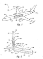
- Figure 1 is a top isometric view of an aircraft 100 having a wing/winglet combination 105 configured in accordance with an embodiment of the disclosure.
- the aircraft 100 includes a lifting surface such as a wing 110 extending outwardly from a fuselage 102.
- the fuselage 102 can be aligned along a longitudinal axis 101 and can include a passenger compartment 103 configured to carry a plurality of passengers (not shown).
- the passenger compartment 103 can be configured to carry at least 50 passengers.
- the passenger compartment 103 can be configured to carry at least 150 passengers.
- the passenger compartment 103 can be configured to carry other numbers of passengers, and in still other embodiments (such as military embodiments), the passenger compartment 103 can be omitted or can be configured to carry cargo.
- the wing 110 has an inboard portion 111 that includes the wing root, and an outboard portion 112 that includes the wing tip.
- the wing 110 also includes a winglet 130.
- the winglet 130 can be added to an existing wing design, and in other cases, the wing 110 and the winglet 130 can be designed together. In either case, the winglets 130 can be particularly selected and/or configured to account for constraints associated with the design of the wing 110.
- the winglet 130 of the illustrated embodiment is combined with a wing
- the winglet 130 can be combined with other types of lifting surfaces to reduce aerodynamic drag and/or serve other purposes.
- the winglet 130 can be combined with a forward-wing or canard to reduce the aerodynamic drag on the canard.
- the winglet 130 can be combined with other lifting surfaces.
- the winglets can be vertical, while in other embodiments, the winglets can be canted from the vertical. Embodiments in which the winglets are vertical or at least canted upwardly from the horizontal can be particularly useful for reducing space occupied by the aircraft 100 at an airport gate.
- Figure 2 is a partially schematic, isometric view (looking generally aft and slightly outboard) of an outboard portion 112 of the wing 110, along with the winglet 130.
- the wing 110 includes an upper surface 126 and extends outboard along a wing spanwise axis 113, and extends fore and aft along a wing chordwise axis 114 between a wing leading edge 115 and a wing trailing edge 116.
- the wing 110 includes a wing/winglet junction 117 at which the wing 110 transitions to the winglet 130.
- the junction 117 can be generally curved and/or gradual to reduce flow interference between the wing 110 and the winglet 130.
- the junction 117 can have other shapes and/or configurations, including a sharp corner and/or a tight radius corner.
- sharp corner refers to a corner that includes a surface discontinuity and/or sudden change in shape, e.g., a non-gradual change in slope.
- the winglet 130 includes a first (e.g., inboard-facing) surface 131 and a second (e.g., outboard-facing) surface 132. The winglet 130 extends away from the wing 110 along a winglet spanwise axis 133, and extends fore and aft along a winglet chordwise axis 134.
- the winglet 130 further includes a recessed region 150 located in the first surface 131.
- the recessed region 150 can be particularly sized and located to account for (e.g., reduce or eliminate) possible interference effects between the wing 110 and the winglet 130 in the region of the wing/winglet junction 117.
- the recessed region 150 is bounded by adjacent regions 151 that are not recessed.
- Such adjacent regions 151 can include a forward adjacent region 151a, an aft adjacent region 151b, an upper or distal adjacent region 151c and a lower or proximal adjacent region 151d.
- the adjacent regions 151 can be convex, in contrast to the concave recessed region 150.
- the recessed region 150 is generally pear-shaped. Accordingly, the chordwise extent of the recessed region 150 can decrease in an upward/outward direction along the winglet spanwise axis 133.
- the illustrated recessed region 150 is roughly bounded by four points 152, including a forward-most point 152a, an aft-most point 152b, an uppermost or distal point 152c, and a lowermost or proximal point 152d.
- the recessed region 150 can have other shapes and/or boundaries.
- the location of the forward-most point 152a can range from about 20% to about 40% of the local chordlength of the winglet 130, and the location of the aft-most point 152b can range from about 45% to about 65% of the local chordlength.
- the recessed region extends from about 25% of the local chordlength to about 65% of the local chordlength over its spanwise extent.
- the location of the uppermost point 152c can range from about 20% to about 40% (e.g., about 30%) of the spanwise dimension of the winglet 130, and the location of the lowermost point 152d can range from about 0% to about 20% of the spanwise dimension of the winglet.
- These locations can have other values and other embodiments, depending upon the particular installation, the orientation of the winglet 130 relative to the wing 110, and/or other design and/or operation features.
- Figure 3 is a rear view (looking forward) of a portion of the wing 110 and the winglet 130 shown in Figure 2 .
- Figure 3 accordingly illustrates the recessed region 150 from the rear, indicating the overall shape of the recessed region 150 and its location relative to both the winglet 130 (including the winglet trailing edge 136) and the wing 110.
- Figure 4 is a front view (looking rearward) of the wing 110 and the winglet 130 shown in Figures 2 and 3 , indicating representative wing sections 118, and representative winglet sections 137 (shown as first-sixth winglet sections 137a-137f).
- the first winglet section 137a is taken at a region positioned downward/inboard from the recessed region 150
- the sixth winglet section 137f is taken at a location that is above/outboard of the recessed region 150.
- the intermediate winglet sections 137b-137e intersect the recessed region 150 and are described in further detail below with reference to Figures 5A-7 .
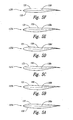
- FIGS 5A-5F illustrate the winglet chord sections 137a-137f, respectively, described initially above with reference to Figure 4 .
- the leading edge portions of the winglet chord sections 137a-137f are illustrated with a representative contour that may be different in different embodiments.
- each winglet chord section 137a-137f includes a camber line 138, illustrated as corresponding first-sixth camber lines 138a-138f.
- the camber distribution for each chordwise section is non-monotonic, and the chordwise camber distribution varies in a non-monotonic manner along the spanwise axis of the winglet 130 in the recessed region 150.
- the camber line is generally flat below/inboard of the recessed region 150 (see camber line 138a), becomes concave or more concave in the recessed region 150 (see camber lines 138b-138e), and then becomes generally flat or less concave at a distal spanwise location above/outboard of the recessed region 150 (see camber line 138f).
- the first surface 131 of the winglet 130 has a similar, non-monotonic variation as the sections progress in a distal direction along the spanwise axis. Accordingly, as used herein, the term non-monotonic is used to describe a variation that changes in sense or direction, e.g., a contour that initially becomes more concave and then becomes less concave.
- Figure 6 illustrates the six winglet sections 137a-137f together, with the vertical scale exaggerated to highlight the presence of the recessed region 150.
- Figure 7 illustrates the six camber lines 138a-138f together to indicate the variation of the camber lines in the recessed region.
- Figure 6 illustrates the non-monotonic change in shape of the winglet first surface 131 in the recessed region 150 (see chord sections 137a-137f), and
- Figure 7 illustrates the corresponding non-monotonic change in shape of the camber lines 138a-138f in the recessed region 150.
- one expected advantage of embodiments of the winglet 130 that include the recessed region 150 is that the recessed region 150 can reduce or eliminate flow interference effects caused by the juxtaposition of the winglet 130 and the wing 110.
- separated flow may develop at the wing/winglet junction 117, which can increase drag and/or reduce lift and in either case, can adversely affect aircraft performance.
- the recess 150 can also reduce or eliminate the likelihood for a "double-shock" pressure field in this region.
- the recess 150 can reduce the aerodynamic compression in the junction region 117 to reduce or eliminate such a shock pattern.
- the recessed region 150 can have particular benefit when incorporated into a winglet 130 that is added to an existing wing to reduce drag, but, due to constraints on the spanwise extent of the modified wing, benefits from or requires a wing/winglet junction 117 with a tight or sharp corner.
- the recessed region 150 can be applied to the winglet 130 without affecting the wing upper surface 126.
- the wing upper surface 126 need not include a flat region or a concave or recessed region to provide the foregoing aerodynamic advantages, because it is expected that the recess 150 in the winglet 130 will be at least adequate to do so.
- an advantage of this arrangement is that the winglet 130 can be retrofitted to an existing and/or aerodynamically optimized wing 110.
- Figure 8 illustrates a representative process 160 for designing a winglet.
- the process 160 includes providing a design for a wing that includes airfoil sections (e.g., the wing sections 118 shown in Figure 4 ) extending from an inboard region to an outboard region of the wing (process portion 161).
- the method further includes designing a winglet for use with the wing, without changing the general shapes of the wing airfoil sections (process portion 165).
- the winglet can have a first surface facing generally inboard and a second surface facing generally outboard away from the first surface.
- Designing the winglet further includes at least reducing a performance impact of flow at a junction region of the wing and the winglet by designing a concave recess in the first surface of the winglet.
- the concave recess can be defined by a variety of methods, e.g., by altering the lines of an existing airfoil section in the recessed region, and/or by altering the lines of an existing airfoil section outside the recessed region (e.g., by "building up" regions outside the recessed region).
- the process for developing the winglet contours can be iterative, and can include developing an initial winglet loft (process portion 166) and analyzing the performance of the loft (process portion 167).
- the loft can be analyzed to determine whether it meets target performance levels.
- the loft can be assessed using computational fluid dynamics (CFD) tools and/or wind tunnel testing to determine whether preselected target performance levels are met. If not, the initially developed loft can be revised (process portion 166) until performance levels are met, at which point the process can end.
- CFD computational fluid dynamics
- the winglets can have different cant angles, different spanwise and/or chordwise extents and/or different configurations than are specifically identified in the Figures.
- Such configurations can include winglets that extend both above and below the wing, and/or spiroid winglets, and/or wingtip feathers.
- the recessed regions may also have different locations and/or extents depending upon the particular installation. Certain aspects of the disclosure described in the context of particular embodiments may be combined or eliminated in other embodiments.
Landscapes
- Engineering & Computer Science (AREA)
- Aviation & Aerospace Engineering (AREA)
- Structures Of Non-Positive Displacement Pumps (AREA)
- Toys (AREA)
Description
- The following disclosure relates generally to winglets with recessed surfaces, and associated systems and methods.
- The idea of using winglets to reduce induced drag on aircraft wings was studied by Richard Whitcomb of NASA and others in the 1970s. Since then, a number of variations on this idea have been patented (see, for example,
U.S 4,205,810 ,U.S. 4,382,569 ,U.S. 2004/0155146 , the closest prior art, andU.S. 5,275,358 ). In addition, a number of tip device variations are currently in service. Such devices include horizontal span extensions and aft-swept span extensions that are canted upward or downward at various angles. These devices can be added to a new wing during the initial design phase of an all-new aircraft, or they can be added to an existing wing as a retrofit or during development of a derivative model. - The induced drag of a wing or a wing/winglet combination can be calculated with reasonable accuracy using the classic "Trefftz plane theory." According to this theory, the induced drag of an aircraft wing depends only on the trailing edge trace of the "lifting system" (i.e., the wing plus tip device), as viewed directly from the front or rear of the wing, and the "spanload." The spanload is the distribution of aerodynamic load perpendicular to the trailing edge trace of the wing. Aerodynamicists often refer to this aerodynamic load distribution as "lift," even though the load is not vertical when the trailing edge trace is tilted from horizontal. Adding a winglet or other wing tip device to a wing changes both the trailing edge trace (i.e., the "Trefftz-plane geometry") and the spanload. As a result, adding such a device also changes the induced drag on the wing.
- For a given Trefftz-plane geometry and a given total vertical lift, there is generally one spanload that gives the lowest possible induced drag. This is the "ideal spanload," and the induced drag that results from the ideal spanload is the "ideal induced drag." For a flat wing where the Trefftz-plane geometry is a horizontal line, the ideal spanload is elliptical. Conventional aircraft wings without winglets are close enough to being flat in the Trefftz-plane that their ideal spanloads are very close to elliptical. For conventional aircraft wings having vertical or near-vertical winglets (i.e., nonplanar lifting systems), the ideal spanload is generally not elliptical, but the ideal spanload can be easily calculated from conventional wing theory.
- Conventional aircraft wings are generally not designed with ideal or elliptical spanloads. Instead, they are designed with compromised "triangular" spanloads that reduce structural bending loads on the wing. Such designs trade a slight increase in induced drag for a reduction in airframe weight. The degree of compromise varies considerably from one aircraft model to another. To produce such a triangular spanload, the wing tip is typically twisted to produce "washout." Washout refers to a wing that twists in an outboard direction so that the trailing edge moves upward relative to the leading edge. Washing out the wing tip in this manner lowers the angle of attack of the wing tip with respect to the wing root, thereby reducing the lift distribution toward the wing tip.
- Designing a new wing and developing the associated tooling for a new wing is an expensive undertaking. Accordingly, some aircraft manufacturers develop derivative wing designs that are based at least in part on an initial design. While such designs can be less expensive to develop, they typically include at least some performance compromises. Accordingly, there remains a need for improved, cost-effective wing development processes.
- The present invention provides an aircraft system according to claim 1, and a method for reducing aircraft system drag according to claim 8.
- The present disclosure is directed generally to winglets with recessed surfaces, and associated systems and methods. A system in accordance with a particular embodiment includes a wing having an inboard portion and an outboard portion, and a winglet coupled to the wing at the outboard portion. The winglet has a first surface facing at least partially inboard and a second surface facing at least partially outboard, with the first surface including a recessed region. The recessed region can be concave relative to adjacent regions of the first surface, and the adjacent regions can include regions located on both sides of the recessed region in a chordwise direction, and a region positioned away from the wing along the spanwise axis of the winglet. Other aspects of the disclosure are directed to methods for designing an aircraft system. One such method includes providing a design for a wing that includes airfoil sections from an inboard region to an outboard region of the wing. The method further includes designing a winglet for use with the wing without changing the general shapes of the wing airfoil sections. The winglet has a first surface facing generally inboard and a second surface facing generally outboard away from the first surface. Designing the winglet includes at least reducing a performance impact of flow at a junction region of the wing and the winglet by designing a concave recess in the first surface of the winglet.
-
-
Figure 1 is a partially schematic, isometric illustration of an aircraft having wings and wingtip devices configured in accordance with an embodiment of the disclosure. -
Figure 2 is a partially schematic, isometric illustration of an outboard wing portion and winglet having a recessed region in accordance with a particular embodiment of the disclosure. -
Figure 3 is a rear view (looking forward) of a portion of the wing and winglet shown inFigure 2 . -
Figure 4 is a front view (looking rearward) of a portion of the wing and winglet shown inFigure 2 , with particular winglet sections identified. -
Figures 5A-5F are nondimensionalized, cross-sectional illustrations of the winglet sections identified inFigure 4 . -
Figure 6 is a composite of the winglet sections shown inFigures 5A-5F , with the vertical scale exaggerated for purposes of illustration. -
Figure 7 is a composite of the winglet camber lines shown inFigures 5A-5F , with the vertical scale exaggerated for purposes of illustration. -
Figure 8 is a flow diagram illustrating a method in accordance with a particular embodiment of the disclosure. - The following disclosure describes winglets with recessed surfaces, and associated systems and methods. Certain specific details are set forth in the following description and in
Figures 1-8 to provide a thorough understanding of various embodiments of the disclosure. Other details describing well-known structures and systems often associated with aircraft and aircraft wings are not set forth in the following description to avoid unnecessarily obscuring the description of the various embodiments. - Many of the details, dimensions, angles and other specifications shown in the Figures are merely illustrative of particular embodiments. Accordingly, other embodiments can have other details, dimensions, and specifications without departing from the present disclosure. In addition, other embodiments may be practiced without several of the details described below.
-
Figure 1 is a top isometric view of anaircraft 100 having a wing/winglet combination 105 configured in accordance with an embodiment of the disclosure. In one aspect of this embodiment, theaircraft 100 includes a lifting surface such as awing 110 extending outwardly from afuselage 102. Thefuselage 102 can be aligned along alongitudinal axis 101 and can include apassenger compartment 103 configured to carry a plurality of passengers (not shown). In one embodiment, thepassenger compartment 103 can be configured to carry at least 50 passengers. In another embodiment, thepassenger compartment 103 can be configured to carry at least 150 passengers. In further embodiments, thepassenger compartment 103 can be configured to carry other numbers of passengers, and in still other embodiments (such as military embodiments), thepassenger compartment 103 can be omitted or can be configured to carry cargo. - The
wing 110 has aninboard portion 111 that includes the wing root, and anoutboard portion 112 that includes the wing tip. Thewing 110 also includes awinglet 130. In some cases, thewinglet 130 can be added to an existing wing design, and in other cases, thewing 110 and thewinglet 130 can be designed together. In either case, thewinglets 130 can be particularly selected and/or configured to account for constraints associated with the design of thewing 110. - Although the
winglet 130 of the illustrated embodiment is combined with a wing, in other embodiments, thewinglet 130 can be combined with other types of lifting surfaces to reduce aerodynamic drag and/or serve other purposes. For example, in one other embodiment, thewinglet 130 can be combined with a forward-wing or canard to reduce the aerodynamic drag on the canard. In further embodiments, thewinglet 130 can be combined with other lifting surfaces. In particular embodiments, the winglets can be vertical, while in other embodiments, the winglets can be canted from the vertical. Embodiments in which the winglets are vertical or at least canted upwardly from the horizontal can be particularly useful for reducing space occupied by theaircraft 100 at an airport gate. -
Figure 2 is a partially schematic, isometric view (looking generally aft and slightly outboard) of anoutboard portion 112 of thewing 110, along with thewinglet 130. Thewing 110 includes anupper surface 126 and extends outboard along awing spanwise axis 113, and extends fore and aft along a wingchordwise axis 114 between awing leading edge 115 and awing trailing edge 116. At theoutboard portion 112, thewing 110 includes a wing/winglet junction 117 at which thewing 110 transitions to thewinglet 130. In a particular embodiment, thejunction 117 can be generally curved and/or gradual to reduce flow interference between thewing 110 and thewinglet 130. In other embodiments, thejunction 117 can have other shapes and/or configurations, including a sharp corner and/or a tight radius corner. As used herein, the term sharp corner refers to a corner that includes a surface discontinuity and/or sudden change in shape, e.g., a non-gradual change in slope. In any of these embodiments, thewinglet 130 includes a first (e.g., inboard-facing)surface 131 and a second (e.g., outboard-facing)surface 132. Thewinglet 130 extends away from thewing 110 along awinglet spanwise axis 133, and extends fore and aft along a wingletchordwise axis 134. - The
winglet 130 further includes a recessedregion 150 located in thefirst surface 131. The recessedregion 150 can be particularly sized and located to account for (e.g., reduce or eliminate) possible interference effects between thewing 110 and thewinglet 130 in the region of the wing/winglet junction 117. In a particular embodiment, the recessedregion 150 is bounded byadjacent regions 151 that are not recessed. Suchadjacent regions 151 can include a forwardadjacent region 151a, an aftadjacent region 151b, an upper or distaladjacent region 151c and a lower or proximaladjacent region 151d. Theadjacent regions 151 can be convex, in contrast to the concave recessedregion 150. - In a particular embodiment shown in
Figure 2 , the recessedregion 150 is generally pear-shaped. Accordingly, the chordwise extent of the recessedregion 150 can decrease in an upward/outward direction along thewinglet spanwise axis 133. The illustrated recessedregion 150 is roughly bounded by fourpoints 152, including aforward-most point 152a, anaft-most point 152b, an uppermost ordistal point 152c, and a lowermost orproximal point 152d. In other embodiments, the recessedregion 150 can have other shapes and/or boundaries. - In a representative embodiment, the location of the
forward-most point 152a can range from about 20% to about 40% of the local chordlength of thewinglet 130, and the location of theaft-most point 152b can range from about 45% to about 65% of the local chordlength. In a particular embodiment, the recessed region extends from about 25% of the local chordlength to about 65% of the local chordlength over its spanwise extent. The location of theuppermost point 152c can range from about 20% to about 40% (e.g., about 30%) of the spanwise dimension of thewinglet 130, and the location of thelowermost point 152d can range from about 0% to about 20% of the spanwise dimension of the winglet. These locations can have other values and other embodiments, depending upon the particular installation, the orientation of thewinglet 130 relative to thewing 110, and/or other design and/or operation features. -
Figure 3 is a rear view (looking forward) of a portion of thewing 110 and thewinglet 130 shown inFigure 2 .Figure 3 accordingly illustrates the recessedregion 150 from the rear, indicating the overall shape of the recessedregion 150 and its location relative to both the winglet 130 (including the winglet trailing edge 136) and thewing 110. -
Figure 4 is a front view (looking rearward) of thewing 110 and thewinglet 130 shown inFigures 2 and3 , indicatingrepresentative wing sections 118, and representative winglet sections 137 (shown as first-sixth winglet sections 137a-137f). Thefirst winglet section 137a is taken at a region positioned downward/inboard from the recessedregion 150, and thesixth winglet section 137f is taken at a location that is above/outboard of the recessedregion 150. Theintermediate winglet sections 137b-137e intersect the recessedregion 150 and are described in further detail below with reference toFigures 5A-7 . -
Figures 5A-5F illustrate thewinglet chord sections 137a-137f, respectively, described initially above with reference toFigure 4 . The leading edge portions of thewinglet chord sections 137a-137f are illustrated with a representative contour that may be different in different embodiments. As is also illustrated inFigures 5A-5F , eachwinglet chord section 137a-137f includes a camber line 138, illustrated as corresponding first-sixth camber lines 138a-138f. As is evident fromFigures 5A-5F , the camber distribution for each chordwise section is non-monotonic, and the chordwise camber distribution varies in a non-monotonic manner along the spanwise axis of thewinglet 130 in the recessedregion 150. In particular, the camber line is generally flat below/inboard of the recessed region 150 (seecamber line 138a), becomes concave or more concave in the recessed region 150 (seecamber lines 138b-138e), and then becomes generally flat or less concave at a distal spanwise location above/outboard of the recessed region 150 (seecamber line 138f). Thefirst surface 131 of thewinglet 130 has a similar, non-monotonic variation as the sections progress in a distal direction along the spanwise axis. Accordingly, as used herein, the term non-monotonic is used to describe a variation that changes in sense or direction, e.g., a contour that initially becomes more concave and then becomes less concave. -
Figure 6 illustrates the sixwinglet sections 137a-137f together, with the vertical scale exaggerated to highlight the presence of the recessedregion 150.Figure 7 illustrates the sixcamber lines 138a-138f together to indicate the variation of the camber lines in the recessed region.Figure 6 illustrates the non-monotonic change in shape of the wingletfirst surface 131 in the recessed region 150 (seechord sections 137a-137f), andFigure 7 illustrates the corresponding non-monotonic change in shape of thecamber lines 138a-138f in the recessedregion 150. - Returning briefly to
Figure 2 , one expected advantage of embodiments of thewinglet 130 that include the recessedregion 150 is that the recessedregion 150 can reduce or eliminate flow interference effects caused by the juxtaposition of thewinglet 130 and thewing 110. In particular, without the recessedregion 150, separated flow may develop at the wing/winglet junction 117, which can increase drag and/or reduce lift and in either case, can adversely affect aircraft performance. Therecess 150 can also reduce or eliminate the likelihood for a "double-shock" pressure field in this region. In particular, therecess 150 can reduce the aerodynamic compression in thejunction region 117 to reduce or eliminate such a shock pattern. This, in turn, can reduce the drag of the aircraft 100 (Figure 1 ) and can improve the high-speed buffet margin of thewing 110, when compared with a wing that includes a winglet without such a feature. In general, it is expected that the tighter the corner of the wing/winglet junction 117, the greater the potential benefit of the recessedregion 150. Accordingly, the recessedregion 150 can have particular benefit when incorporated into awinglet 130 that is added to an existing wing to reduce drag, but, due to constraints on the spanwise extent of the modified wing, benefits from or requires a wing/winglet junction 117 with a tight or sharp corner. - Another particular advantage of the foregoing arrangement is that the recessed
region 150 can be applied to thewinglet 130 without affecting the wingupper surface 126. In particular, the wingupper surface 126 need not include a flat region or a concave or recessed region to provide the foregoing aerodynamic advantages, because it is expected that therecess 150 in thewinglet 130 will be at least adequate to do so. Accordingly, an advantage of this arrangement is that thewinglet 130 can be retrofitted to an existing and/or aerodynamically optimizedwing 110. -
Figure 8 illustrates arepresentative process 160 for designing a winglet. Theprocess 160 includes providing a design for a wing that includes airfoil sections (e.g., thewing sections 118 shown inFigure 4 ) extending from an inboard region to an outboard region of the wing (process portion 161). The method further includes designing a winglet for use with the wing, without changing the general shapes of the wing airfoil sections (process portion 165). The winglet can have a first surface facing generally inboard and a second surface facing generally outboard away from the first surface. Designing the winglet further includes at least reducing a performance impact of flow at a junction region of the wing and the winglet by designing a concave recess in the first surface of the winglet. The concave recess can be defined by a variety of methods, e.g., by altering the lines of an existing airfoil section in the recessed region, and/or by altering the lines of an existing airfoil section outside the recessed region (e.g., by "building up" regions outside the recessed region). - In particular embodiments, the process for developing the winglet contours can be iterative, and can include developing an initial winglet loft (process portion 166) and analyzing the performance of the loft (process portion 167). In
process portion 168, the loft can be analyzed to determine whether it meets target performance levels. For example, the loft can be assessed using computational fluid dynamics (CFD) tools and/or wind tunnel testing to determine whether preselected target performance levels are met. If not, the initially developed loft can be revised (process portion 166) until performance levels are met, at which point the process can end. - From the foregoing, it will be appreciated that specific embodiments of the disclosure have been described herein for purposes of illustration, but that various modifications may be made in other embodiments. For example, the winglets can have different cant angles, different spanwise and/or chordwise extents and/or different configurations than are specifically identified in the Figures. Such configurations can include winglets that extend both above and below the wing, and/or spiroid winglets, and/or wingtip feathers. The recessed regions may also have different locations and/or extents depending upon the particular installation. Certain aspects of the disclosure described in the context of particular embodiments may be combined or eliminated in other embodiments. Further, while advantages associated with certain embodiments have been described in the context of those embodiments, other embodiments may also exhibit such advantages, and not all embodiments need necessarily exhibit such advantages to fall within the scope of the disclosure. Accordingly, the disclosure can include other embodiments not specifically described or shown above.
Claims (13)
- An aircraft system, comprising:a wing (110) having an inboard portion (111) and an outboard portion (112); anda winglet (130) coupled to the wing at the outboard portion, the winglet having a first surface (131) facing at least partially inboard and a second surface (132) facing at least partially outboard wherein the first and second surfaces are external surfaces when the winglet is coupled to the wing, and characterised by the first external surface including a recessed region (150).
- The system of claim 1 wherein the recessed region is concave relative to adjacent regions (151) of the first external surface, the adjacent regions including regions located on both sides of the recessed region in a chordwise direction, and including a region positioned away from the wing in a spanwise direction.
- The system of claim 1 wherein the winglet has a leading edge and a trailing edge, and wherein the first surface of the winglet is convex near the leading edge, convex near the trailing edge and concave between the leading and trailing edges.
- The system of claim 1 wherein the recessed region has a forwardmost point (152a) and an aftmost point (152b) in a chordwise direction, the recessed region having a proximal point closest to the wing in a spanwise direction and a distal point furthest from the wing in the spanwise direction.
- The system of claim 4 wherein the forwardmost point is located at between about 20% and about 40% of a chordlength of the winglet intersecting the forwardmost point.
- The system of claim 4 wherein the aftmost point is located at between about 45% and about 65% of a chordlength of the winglet intersecting the aftmost point.
- The system of claim 4 wherein the distal point is located at between about 20% and about 40% of a spanwise dimension of the winglet.
- A method for reducing aircraft system drag, comprising:providing a wing (110) that includes airfoil sections from an inboard region (111) to an outboard region (112) of the wing; andproviding a winglet (130) for use with the wing without changing the general shapes of the wing airfoil sections at the outboard region of the wing, the winglet having a first external surface (131) facing generally inboard and a second external surface (132) generally outboard away from the first surface, characterised in that the winglet includes at least reducing a performance impact of flow at a junction region (117) of the wing and winglet with a concave recess (150) in the first external surface of the winglet.
- The method of claim 8, wherein a winglet includes a concave recess with a forwardmost point and an aftmost point in a chordwise direction, the concave recess having a proximal point closest to the wing in a spanwise direction and a distal point furthest from the wing in the spanwise direction.
- The method of claim 9, wherein the forwardmost point to be located at between about 20% and about 40% of a chordlength of the winglet intersecting the forwardmost point.
- The method of claim 9, wherein the aftmost point to be located at between about 45% and about 65% of a chordlength of the winglet intersecting the aftmost point.
- The method of claim 8 wherein a concave recess includes a recess into an existing winglet loft.
- The method of claim 8 wherein a concave recess includes built up regions of an existing winglet loft in a forward region and an aft region of the winglet.
Applications Claiming Priority (2)
| Application Number | Priority Date | Filing Date | Title |
|---|---|---|---|
| US12/103,430 US8128035B2 (en) | 2008-04-15 | 2008-04-15 | Winglets with recessed surfaces, and associated systems and methods |
| PCT/US2009/037868 WO2009129023A1 (en) | 2008-04-15 | 2009-03-20 | Winglets with recessed surfaces, and associated systems and methods |
Publications (2)
| Publication Number | Publication Date |
|---|---|
| EP2276665A1 EP2276665A1 (en) | 2011-01-26 |
| EP2276665B1 true EP2276665B1 (en) | 2015-05-06 |
Family
ID=40887190
Family Applications (1)
| Application Number | Title | Priority Date | Filing Date |
|---|---|---|---|
| EP20090733553 Not-in-force EP2276665B1 (en) | 2008-04-15 | 2009-03-20 | Winglets with recessed surfaces, and associated systems and methods |
Country Status (7)
| Country | Link |
|---|---|
| US (1) | US8128035B2 (en) |
| EP (1) | EP2276665B1 (en) |
| JP (1) | JP5490097B2 (en) |
| CN (1) | CN102089207B (en) |
| CA (1) | CA2713162C (en) |
| RU (1) | RU2492111C2 (en) |
| WO (1) | WO2009129023A1 (en) |
Families Citing this family (37)
| Publication number | Priority date | Publication date | Assignee | Title |
|---|---|---|---|---|
| DE102006055090A1 (en) * | 2006-11-21 | 2008-05-29 | Airbus Deutschland Gmbh | Wing i.e. airfoil wing, end form for wing of commercial aircraft, has transition area arranged between wing and winglet, where local V-form changes continuously from wing to winglet in transition area |
| US7900876B2 (en) * | 2007-08-09 | 2011-03-08 | The Boeing Company | Wingtip feathers, including forward swept feathers, and associated aircraft systems and methods |
| US20090084904A1 (en) * | 2007-10-02 | 2009-04-02 | The Boeing Company | Wingtip Feathers, Including Paired, Fixed Feathers, and Associated Systems and Methods |
| US8128035B2 (en) * | 2008-04-15 | 2012-03-06 | The Boeing Company | Winglets with recessed surfaces, and associated systems and methods |
| ES2561982T3 (en) | 2008-06-20 | 2016-03-01 | Aviation Partners, Inc. | Curved wing tip |
| US9302766B2 (en) * | 2008-06-20 | 2016-04-05 | Aviation Partners, Inc. | Split blended winglet |
| DE102009019542A1 (en) * | 2009-04-30 | 2010-11-11 | Airbus Deutschland Gmbh | Non-planar wing tail for airplanes of aircraft and wings with such wing tail |
| US9162755B2 (en) | 2009-12-01 | 2015-10-20 | Tamarack Aerospace Group, Inc. | Multiple controllable airflow modification devices |
| US20110127383A1 (en) | 2009-12-01 | 2011-06-02 | Guida Associates Consulting, Inc. | Active winglet |
| GB201011843D0 (en) * | 2010-07-14 | 2010-09-01 | Airbus Operations Ltd | Wing tip device |
| CA2838848C (en) * | 2011-06-09 | 2020-09-29 | Aviation Partners, Inc. | The split spiroid |
| CN102442422A (en) * | 2011-11-04 | 2012-05-09 | 哈尔滨飞机工业集团有限责任公司 | Winglet for increasing pneumatic efficiency of horizontal tail of time-domain airplane |
| US8936219B2 (en) | 2012-03-30 | 2015-01-20 | The Boeing Company | Performance-enhancing winglet system and method |
| US9086053B2 (en) | 2012-03-30 | 2015-07-21 | General Electric Company | Enhanced wind turbine blade |
| US9567066B2 (en) * | 2013-02-05 | 2017-02-14 | Tamarack Aerospace Group, Inc. | Controllable airflow modification device periodic load control |
| US10696387B2 (en) | 2013-09-27 | 2020-06-30 | Dann M Allen | Helicopter rotor with a mechanical means for configuring rotor tips to control brown outs |
| US10562613B2 (en) * | 2013-12-04 | 2020-02-18 | Tamarack Aerospace Group, Inc. | Adjustable lift modification wingtip |
| USD754053S1 (en) * | 2014-02-19 | 2016-04-19 | Aeronautical Testing Service, Inc. | Wing root leading edge extension |
| US9511850B2 (en) | 2014-04-12 | 2016-12-06 | The Boeing Company | Wing tip device for an aircraft wing |
| GB201512480D0 (en) * | 2015-07-16 | 2015-08-19 | Fourth Dimensional Aerospace Technology Ltd | Fluid flow control for an aerofoil |
| US10690112B2 (en) | 2016-06-27 | 2020-06-23 | William Scott Keeley | Fluid turbine rotor blade with winglet design |
| EP3269635A1 (en) * | 2016-07-12 | 2018-01-17 | The Aircraft Performance Company UG | Airplane wing |
| US10202961B2 (en) | 2016-11-30 | 2019-02-12 | William Scott Keeley | Fluid turbine semi-shroud and associated rotor blade dual-winglet design |
| US10293915B2 (en) | 2016-12-13 | 2019-05-21 | The Boeing Company | Apparatuses and methods for aerodynamic window assemblies |
| GB2559969A (en) * | 2017-02-22 | 2018-08-29 | Airbus Operations Ltd | A method of designing a winglet and winglet disigned thereby |
| US11312481B2 (en) | 2017-07-12 | 2022-04-26 | The Aircraft Performance Company Gmbh | Airplane wing |
| EP3498597B1 (en) | 2017-12-15 | 2020-08-05 | The Aircraft Performance Company GmbH | Airplane wing |
| EP3511243B1 (en) * | 2018-01-15 | 2021-12-29 | The Aircraft Performance Company GmbH | Airplane wing |
| GB2573281B (en) * | 2018-04-25 | 2020-12-30 | Airbus Operations Ltd | An aircraft wing and wing tip device |
| GB2576929A (en) * | 2018-09-07 | 2020-03-11 | Airbus Operations Ltd | A wing tip device |
| CN109885894B (en) * | 2019-01-24 | 2023-05-05 | 江西理工大学 | A Groundwater Seepage Model of Rare Earth Ore Seams Based on Trefftz Multi-source Point Collocation Method |
| CN110080939A (en) * | 2019-06-05 | 2019-08-02 | 上海电气风电集团有限公司 | A kind of vortex generator, fan blade and its manufacturing method |
| CN112124561B (en) * | 2020-09-27 | 2022-02-25 | 中国商用飞机有限责任公司 | Aerodynamic drag reduction structure for winglets of aircraft and aircraft |
| GB2615311A (en) * | 2022-01-31 | 2023-08-09 | Airbus Operations Ltd | Aircraft wing with movable wing tip device |
| GB2616252A (en) * | 2022-01-31 | 2023-09-06 | Airbus Operations Ltd | Aircraft with movable wing tip device |
| GB2628523B (en) * | 2022-11-16 | 2025-07-09 | Airbus Operations Ltd | Aircraft wing |
| CN120057248B (en) * | 2025-04-17 | 2025-11-28 | 白鲸航线(常州)科技有限公司 | Wing tip winglet and aircraft wing |
Family Cites Families (83)
| Publication number | Priority date | Publication date | Assignee | Title |
|---|---|---|---|---|
| DE634884C (en) | 1936-09-05 | Hamburger Flugzeugbau G M B H | Carrying spar for airplanes consisting of approximately semicircular shells | |
| US1354677A (en) * | 1918-04-08 | 1920-10-05 | Melville W Mix | Knockdown airplane-fuselage and process therefor |
| US1888418A (en) * | 1921-04-14 | 1932-11-22 | Adams Herbert Luther | Flying machine |
| US1466551A (en) * | 1921-12-06 | 1923-08-28 | Bristol Aeroplane Co Ltd | Aircraft, submarine, torpedo, and other totally immersed craft or structure |
| US1841921A (en) * | 1929-12-04 | 1932-01-19 | Spiegel Jacob | Airplane construction |
| US2370801A (en) * | 1941-05-14 | 1945-03-06 | Cons Vultee Aireraft Corp | Airplane wing structure |
| US2576981A (en) * | 1949-02-08 | 1951-12-04 | Vogt Richard | Twisted wing tip fin for airplanes |
| US2743888A (en) * | 1951-10-20 | 1956-05-01 | Collins Radio Co | Variable wing |
| US2750134A (en) * | 1952-04-17 | 1956-06-12 | Lockheed Aircraft Corp | Multiple wheel main landing gear |
| US2749061A (en) * | 1954-06-18 | 1956-06-05 | Wesley A Franz | Airplane wing stress compensating structure assembly |
| US3018985A (en) * | 1956-12-31 | 1962-01-30 | Martin Marietta Corp | Swept wing with unswept spar |
| US3027118A (en) * | 1959-01-28 | 1962-03-27 | English Electric Co Ltd | Ram jet propelled aircraft |
| US3270988A (en) * | 1962-12-26 | 1966-09-06 | Jr Clarence D Cone | Minimum induced drag airfoil body |
| US3199813A (en) * | 1964-06-03 | 1965-08-10 | Boeing Co | Aircraft airfoil pods |
| US3273833A (en) * | 1965-01-21 | 1966-09-20 | Dow Chemical Co | Airfoil structure |
| US3712564A (en) * | 1970-11-13 | 1973-01-23 | S Rethorst | Slotted diffuser system for reducing aircraft induced drag |
| DE2149956C3 (en) | 1971-10-07 | 1974-03-28 | Messerschmitt-Boelkow-Blohm Gmbh, 8000 Muenchen | High lift wing |
| US3840199A (en) * | 1972-05-09 | 1974-10-08 | R Tibbs | Aircraft |
| US4045336A (en) * | 1974-08-23 | 1977-08-30 | Pauli Henrik Isteri | Method and device for oxygenating water with vibrations and under pressure strokes |
| US4046336A (en) * | 1975-05-13 | 1977-09-06 | Textron, Inc. | Vortex diffusion and dissipation |
| US4172574A (en) * | 1976-06-16 | 1979-10-30 | National Research Development Corporation | Fluid stream deflecting members for aircraft bodies or the like |
| US4190219A (en) * | 1977-05-17 | 1980-02-26 | Lockheed Corporation | Vortex diffuser |
| US4108403A (en) * | 1977-08-05 | 1978-08-22 | Reginald Vernon Finch | Vortex reducing wing tip |
| US4205810A (en) * | 1977-12-19 | 1980-06-03 | The Boeing Company | Minimum drag wing configuration for aircraft operating at transonic speeds |
| US4382569A (en) * | 1979-12-26 | 1983-05-10 | Grumman Aerospace Corporation | Wing tip flow control |
| US4700911A (en) * | 1982-02-09 | 1987-10-20 | Dornier Gmbh | Transverse driving bodies, particularly airplane wings |
| FR2521520A1 (en) * | 1982-02-15 | 1983-08-19 | Daude Martine | MARGINAL FINS WITH VARIABLE ANGLES OF ATTACK |
| FR2523072A1 (en) * | 1982-03-09 | 1983-09-16 | Cabrol Lucien | AIRCRAFT PROVIDED WITH A MULTIPLE OVERLAPPING SUSPENSION STRUCTURE |
| EP0094064A1 (en) | 1982-05-11 | 1983-11-16 | George Stanmore Rasmussen | Wing tip thrust augmentation system |
| US4455004A (en) * | 1982-09-07 | 1984-06-19 | Lockheed Corporation | Flight control device for airplanes |
| DE3242584A1 (en) * | 1982-11-18 | 1984-05-24 | Messerschmitt-Bölkow-Blohm GmbH, 8000 München | ARRANGEMENT OF ADDITIONAL SURFACES AT THE TIPS OF AN WING |
| EP0113466B1 (en) | 1982-12-30 | 1988-11-30 | The Boeing Company | Tapered thickness-chord ratio wing |
| GB8310224D0 (en) * | 1983-04-15 | 1983-05-18 | British Aerospace | Wing tip arrangement |
| US4595160A (en) * | 1983-05-18 | 1986-06-17 | Jonathan Santos | Wing tip airfoils |
| US4545552A (en) * | 1983-06-20 | 1985-10-08 | Welles Stanley W | Airframe design |
| US4674709A (en) * | 1983-06-20 | 1987-06-23 | Welles Stanley W | Airframe design |
| US4671473A (en) * | 1984-11-08 | 1987-06-09 | Goodson Kenneth W | Airfoil |
| FR2614264B1 (en) * | 1987-04-24 | 1989-07-21 | Aerospatiale | BEARING SYSTEM FOR AIRCRAFT. |
| US4776542A (en) * | 1987-05-27 | 1988-10-11 | Vigyan Research Associates, Inc. | Aircraft stall-spin entry deterrent system |
| US5039032A (en) * | 1988-11-07 | 1991-08-13 | The Boeing Company | High taper wing tip extension |
| US5082204A (en) * | 1990-06-29 | 1992-01-21 | Croston Leon J | All wing aircraft |
| US5102068A (en) * | 1991-02-25 | 1992-04-07 | Gratzer Louis B | Spiroid-tipped wing |
| IL101069A (en) * | 1991-02-25 | 1996-09-12 | Valsan Partners Purchase N Y | System for increasing airplane fuel mileage and airplane wing modification kit |
| US5156358A (en) * | 1991-04-11 | 1992-10-20 | Northrop Corporation | Aircraft outboard control |
| US5378524A (en) * | 1991-05-28 | 1995-01-03 | Blood; Charles L. | Friction reducing surface and devices employing such surfaces |
| US5275358A (en) * | 1991-08-02 | 1994-01-04 | The Boeing Company | Wing/winglet configurations and methods for aircraft |
| US5348253A (en) * | 1993-02-01 | 1994-09-20 | Gratzer Louis B | Blended winglet |
| JPH06255587A (en) * | 1993-03-09 | 1994-09-13 | Honda Motor Co Ltd | aircraft |
| US5395071A (en) * | 1993-09-09 | 1995-03-07 | Felix; Frederick L. | Airfoil with bicambered surface |
| US5634613A (en) * | 1994-07-18 | 1997-06-03 | Mccarthy; Peter T. | Tip vortex generation technology for creating a lift enhancing and drag reducing upwash effect |
| US5788191A (en) * | 1995-08-18 | 1998-08-04 | Sikorsky Aircraft Corporation | Half-plow vortex generators for rotor blades for reducing blade-vortex interaction noise |
| US5897078A (en) * | 1995-12-15 | 1999-04-27 | The Boeing Company | Multi-service common airframe-based aircraft |
| GB9600123D0 (en) * | 1996-01-04 | 1996-03-06 | Westland Helicopters | Aerofoil |
| US5692703A (en) * | 1996-05-10 | 1997-12-02 | Mcdonnell Douglas Corporation | Multiple application wheel well design |
| US6161797A (en) * | 1996-11-25 | 2000-12-19 | Dugan Air Technologies, Inc. | Method and apparatus for reducing airplane noise |
| CA2291275C (en) * | 1997-06-13 | 2007-11-06 | The Boeing Company | Blunt-leading-edge raked wingtips |
| US5909858A (en) * | 1997-06-19 | 1999-06-08 | Mcdonnell Douglas Corporation | Spanwise transition section for blended wing-body aircraft |
| JP2000006893A (en) * | 1998-06-23 | 2000-01-11 | Fuji Heavy Ind Ltd | Composite wing structure |
| FR2780700B1 (en) | 1998-07-02 | 2000-09-29 | Christian Hugues | CYLINDRICAL SPIRAL CAVITY |
| US5975464A (en) * | 1998-09-22 | 1999-11-02 | Scaled Composites, Inc. | Aircraft with removable structural payload module |
| US6474604B1 (en) * | 1999-04-12 | 2002-11-05 | Jerry E. Carlow | Mobius-like joining structure for fluid dynamic foils |
| DE19926832B4 (en) * | 1999-06-12 | 2005-09-15 | Airbus Deutschland Gmbh | Subsonic aircraft preferably with swept-up wings |
| US6484968B2 (en) * | 2000-12-11 | 2002-11-26 | Fort F. Felker | Aircraft with elliptical winglets |
| DE10160315A1 (en) * | 2001-12-07 | 2003-11-13 | Airbus Gmbh | Device for the approach control of an aircraft |
| US6578798B1 (en) * | 2002-04-08 | 2003-06-17 | Faruk Dizdarevic | Airlifting surface division |
| US6547181B1 (en) * | 2002-05-29 | 2003-04-15 | The Boeing Company | Ground effect wing having a variable sweep winglet |
| US6726149B2 (en) * | 2002-05-31 | 2004-04-27 | The Boeing Company | Derivative aircraft and methods for their manufacture |
| US20040135032A1 (en) * | 2002-06-20 | 2004-07-15 | Gregg Robert D | Spanwise tailoring of a trailing edge wedge to a wing |
| AU2003280422A1 (en) * | 2002-06-26 | 2004-01-19 | Peter T. Mccarthy | High efficiency tip vortex reversal and induced drag reduction |
| FR2841532B1 (en) * | 2002-06-27 | 2004-12-17 | Airbus France | AIRCRAFT WITH ACTIVE WINGER TURN CONTROL |
| US7048228B2 (en) * | 2002-10-09 | 2006-05-23 | The Boeing Company | Slotted aircraft wing |
| US6886778B2 (en) | 2003-06-30 | 2005-05-03 | The Boeing Company | Efficient wing tip devices and methods for incorporating such devices into existing wing designs |
| GB0326228D0 (en) * | 2003-11-10 | 2003-12-17 | Airbus Uk Ltd | Wing tip device |
| US7100875B2 (en) * | 2004-02-20 | 2006-09-05 | The Boeing Company | Apparatus and method for the control of trailing wake flows |
| US7264200B2 (en) * | 2004-07-23 | 2007-09-04 | The Boeing Company | System and method for improved rotor tip performance |
| DE102005028688A1 (en) * | 2005-05-19 | 2006-11-30 | Airbus Deutschland Gmbh | Wing unit`s aerodynamic characteristics adapting device for e.g. aircraft, has winglet rotatable in relation to wing unit, such that angle between rotary axis and main direction of extension of unit differs from specified degree |
| US8544800B2 (en) * | 2005-07-21 | 2013-10-01 | The Boeing Company | Integrated wingtip extensions for jet transport aircraft and other types of aircraft |
| FR2894558A1 (en) * | 2005-12-12 | 2007-06-15 | Dassault Avions | Wing for aircraft, has airfoil and winglet defining airfoil zone, winglet zone and connecting zone of winglet and airfoil, where flattened portion in part of connecting zone is central portion of upper surface of profile |
| RU64174U1 (en) * | 2006-11-17 | 2007-06-27 | ООО "Инновационный Центр "Опережение" | END WING SURFACE |
| US7900876B2 (en) * | 2007-08-09 | 2011-03-08 | The Boeing Company | Wingtip feathers, including forward swept feathers, and associated aircraft systems and methods |
| US20090084904A1 (en) * | 2007-10-02 | 2009-04-02 | The Boeing Company | Wingtip Feathers, Including Paired, Fixed Feathers, and Associated Systems and Methods |
| US20090224107A1 (en) * | 2008-03-04 | 2009-09-10 | The Boeing Company | Reduced Span Wings with Wing Tip Devices, and Associated Systems and Methods |
| US8128035B2 (en) * | 2008-04-15 | 2012-03-06 | The Boeing Company | Winglets with recessed surfaces, and associated systems and methods |
-
2008
- 2008-04-15 US US12/103,430 patent/US8128035B2/en not_active Expired - Fee Related
-
2009
- 2009-03-20 EP EP20090733553 patent/EP2276665B1/en not_active Not-in-force
- 2009-03-20 CN CN200980109250.6A patent/CN102089207B/en not_active Expired - Fee Related
- 2009-03-20 CA CA2713162A patent/CA2713162C/en active Active
- 2009-03-20 RU RU2010146134/11A patent/RU2492111C2/en active
- 2009-03-20 JP JP2011505065A patent/JP5490097B2/en not_active Expired - Fee Related
- 2009-03-20 WO PCT/US2009/037868 patent/WO2009129023A1/en not_active Ceased
Also Published As
| Publication number | Publication date |
|---|---|
| RU2010146134A (en) | 2012-05-20 |
| JP2011516345A (en) | 2011-05-26 |
| US20090256029A1 (en) | 2009-10-15 |
| US8128035B2 (en) | 2012-03-06 |
| RU2492111C2 (en) | 2013-09-10 |
| JP5490097B2 (en) | 2014-05-14 |
| CN102089207A (en) | 2011-06-08 |
| EP2276665A1 (en) | 2011-01-26 |
| WO2009129023A1 (en) | 2009-10-22 |
| CA2713162C (en) | 2012-08-21 |
| CA2713162A1 (en) | 2009-10-22 |
| CN102089207B (en) | 2016-07-13 |
Similar Documents
| Publication | Publication Date | Title |
|---|---|---|
| CA2713162C (en) | Winglets with recessed surfaces, and associated systems and methods | |
| US8490925B2 (en) | Non-planar wing tip device for wings of aircraft, and wing comprising such a wing tip device | |
| US8651427B1 (en) | Wing tip device with recess in surface | |
| EP2195236B1 (en) | Wingtip feathers, including paired, fixed feathers, and associated systems and methods | |
| US7988100B2 (en) | Wing tip device | |
| KR101984750B1 (en) | Wingtip device of a wing, and also a wing with such a wingtip device | |
| US7900876B2 (en) | Wingtip feathers, including forward swept feathers, and associated aircraft systems and methods | |
| EP3194263B1 (en) | Split blended winglet | |
| US20090224107A1 (en) | Reduced Span Wings with Wing Tip Devices, and Associated Systems and Methods | |
| US20110024573A1 (en) | Extended winglet with load balancing characteristics | |
| US9027883B2 (en) | Aircraft fairing | |
| CN106218862A (en) | The fixed-wing of airborne vehicle | |
| EP3774527A1 (en) | Elliptical wing tip and method of fabricating same |
Legal Events
| Date | Code | Title | Description |
|---|---|---|---|
| PUAI | Public reference made under article 153(3) epc to a published international application that has entered the european phase |
Free format text: ORIGINAL CODE: 0009012 |
|
| 17P | Request for examination filed |
Effective date: 20101115 |
|
| AK | Designated contracting states |
Kind code of ref document: A1 Designated state(s): AT BE BG CH CY CZ DE DK EE ES FI FR GB GR HR HU IE IS IT LI LT LU LV MC MK MT NL NO PL PT RO SE SI SK TR |
|
| AX | Request for extension of the european patent |
Extension state: AL BA RS |
|
| DAX | Request for extension of the european patent (deleted) | ||
| 17Q | First examination report despatched |
Effective date: 20131112 |
|
| GRAP | Despatch of communication of intention to grant a patent |
Free format text: ORIGINAL CODE: EPIDOSNIGR1 |
|
| INTG | Intention to grant announced |
Effective date: 20140922 |
|
| GRAS | Grant fee paid |
Free format text: ORIGINAL CODE: EPIDOSNIGR3 |
|
| GRAA | (expected) grant |
Free format text: ORIGINAL CODE: 0009210 |
|
| AK | Designated contracting states |
Kind code of ref document: B1 Designated state(s): AT BE BG CH CY CZ DE DK EE ES FI FR GB GR HR HU IE IS IT LI LT LU LV MC MK MT NL NO PL PT RO SE SI SK TR |
|
| REG | Reference to a national code |
Ref country code: GB Ref legal event code: FG4D |
|
| REG | Reference to a national code |
Ref country code: CH Ref legal event code: EP |
|
| REG | Reference to a national code |
Ref country code: IE Ref legal event code: FG4D |
|
| REG | Reference to a national code |
Ref country code: AT Ref legal event code: REF Ref document number: 725490 Country of ref document: AT Kind code of ref document: T Effective date: 20150615 |
|
| REG | Reference to a national code |
Ref country code: DE Ref legal event code: R096 Ref document number: 602009031106 Country of ref document: DE Effective date: 20150618 |
|
| REG | Reference to a national code |
Ref country code: AT Ref legal event code: MK05 Ref document number: 725490 Country of ref document: AT Kind code of ref document: T Effective date: 20150506 |
|
| REG | Reference to a national code |
Ref country code: NL Ref legal event code: MP Effective date: 20150506 |
|
| REG | Reference to a national code |
Ref country code: LT Ref legal event code: MG4D |
|
| PG25 | Lapsed in a contracting state [announced via postgrant information from national office to epo] |
Ref country code: NO Free format text: LAPSE BECAUSE OF FAILURE TO SUBMIT A TRANSLATION OF THE DESCRIPTION OR TO PAY THE FEE WITHIN THE PRESCRIBED TIME-LIMIT Effective date: 20150806 Ref country code: HR Free format text: LAPSE BECAUSE OF FAILURE TO SUBMIT A TRANSLATION OF THE DESCRIPTION OR TO PAY THE FEE WITHIN THE PRESCRIBED TIME-LIMIT Effective date: 20150506 Ref country code: PT Free format text: LAPSE BECAUSE OF FAILURE TO SUBMIT A TRANSLATION OF THE DESCRIPTION OR TO PAY THE FEE WITHIN THE PRESCRIBED TIME-LIMIT Effective date: 20150907 Ref country code: ES Free format text: LAPSE BECAUSE OF FAILURE TO SUBMIT A TRANSLATION OF THE DESCRIPTION OR TO PAY THE FEE WITHIN THE PRESCRIBED TIME-LIMIT Effective date: 20150506 Ref country code: FI Free format text: LAPSE BECAUSE OF FAILURE TO SUBMIT A TRANSLATION OF THE DESCRIPTION OR TO PAY THE FEE WITHIN THE PRESCRIBED TIME-LIMIT Effective date: 20150506 Ref country code: LT Free format text: LAPSE BECAUSE OF FAILURE TO SUBMIT A TRANSLATION OF THE DESCRIPTION OR TO PAY THE FEE WITHIN THE PRESCRIBED TIME-LIMIT Effective date: 20150506 |
|
| PG25 | Lapsed in a contracting state [announced via postgrant information from national office to epo] |
Ref country code: IS Free format text: LAPSE BECAUSE OF FAILURE TO SUBMIT A TRANSLATION OF THE DESCRIPTION OR TO PAY THE FEE WITHIN THE PRESCRIBED TIME-LIMIT Effective date: 20150906 Ref country code: AT Free format text: LAPSE BECAUSE OF FAILURE TO SUBMIT A TRANSLATION OF THE DESCRIPTION OR TO PAY THE FEE WITHIN THE PRESCRIBED TIME-LIMIT Effective date: 20150506 Ref country code: LV Free format text: LAPSE BECAUSE OF FAILURE TO SUBMIT A TRANSLATION OF THE DESCRIPTION OR TO PAY THE FEE WITHIN THE PRESCRIBED TIME-LIMIT Effective date: 20150506 Ref country code: GR Free format text: LAPSE BECAUSE OF FAILURE TO SUBMIT A TRANSLATION OF THE DESCRIPTION OR TO PAY THE FEE WITHIN THE PRESCRIBED TIME-LIMIT Effective date: 20150807 Ref country code: BG Free format text: LAPSE BECAUSE OF FAILURE TO SUBMIT A TRANSLATION OF THE DESCRIPTION OR TO PAY THE FEE WITHIN THE PRESCRIBED TIME-LIMIT Effective date: 20150806 |
|
| PG25 | Lapsed in a contracting state [announced via postgrant information from national office to epo] |
Ref country code: EE Free format text: LAPSE BECAUSE OF FAILURE TO SUBMIT A TRANSLATION OF THE DESCRIPTION OR TO PAY THE FEE WITHIN THE PRESCRIBED TIME-LIMIT Effective date: 20150506 Ref country code: DK Free format text: LAPSE BECAUSE OF FAILURE TO SUBMIT A TRANSLATION OF THE DESCRIPTION OR TO PAY THE FEE WITHIN THE PRESCRIBED TIME-LIMIT Effective date: 20150506 |
|
| REG | Reference to a national code |
Ref country code: DE Ref legal event code: R097 Ref document number: 602009031106 Country of ref document: DE |
|
| PG25 | Lapsed in a contracting state [announced via postgrant information from national office to epo] |
Ref country code: SK Free format text: LAPSE BECAUSE OF FAILURE TO SUBMIT A TRANSLATION OF THE DESCRIPTION OR TO PAY THE FEE WITHIN THE PRESCRIBED TIME-LIMIT Effective date: 20150506 Ref country code: RO Free format text: LAPSE BECAUSE OF NON-PAYMENT OF DUE FEES Effective date: 20150506 Ref country code: PL Free format text: LAPSE BECAUSE OF FAILURE TO SUBMIT A TRANSLATION OF THE DESCRIPTION OR TO PAY THE FEE WITHIN THE PRESCRIBED TIME-LIMIT Effective date: 20150506 Ref country code: CZ Free format text: LAPSE BECAUSE OF FAILURE TO SUBMIT A TRANSLATION OF THE DESCRIPTION OR TO PAY THE FEE WITHIN THE PRESCRIBED TIME-LIMIT Effective date: 20150506 |
|
| PLBE | No opposition filed within time limit |
Free format text: ORIGINAL CODE: 0009261 |
|
| STAA | Information on the status of an ep patent application or granted ep patent |
Free format text: STATUS: NO OPPOSITION FILED WITHIN TIME LIMIT |
|
| REG | Reference to a national code |
Ref country code: FR Ref legal event code: PLFP Year of fee payment: 8 |
|
| 26N | No opposition filed |
Effective date: 20160209 |
|
| PG25 | Lapsed in a contracting state [announced via postgrant information from national office to epo] |
Ref country code: IT Free format text: LAPSE BECAUSE OF FAILURE TO SUBMIT A TRANSLATION OF THE DESCRIPTION OR TO PAY THE FEE WITHIN THE PRESCRIBED TIME-LIMIT Effective date: 20150506 |
|
| PG25 | Lapsed in a contracting state [announced via postgrant information from national office to epo] |
Ref country code: SI Free format text: LAPSE BECAUSE OF FAILURE TO SUBMIT A TRANSLATION OF THE DESCRIPTION OR TO PAY THE FEE WITHIN THE PRESCRIBED TIME-LIMIT Effective date: 20150506 |
|
| PG25 | Lapsed in a contracting state [announced via postgrant information from national office to epo] |
Ref country code: BE Free format text: LAPSE BECAUSE OF FAILURE TO SUBMIT A TRANSLATION OF THE DESCRIPTION OR TO PAY THE FEE WITHIN THE PRESCRIBED TIME-LIMIT Effective date: 20150506 |
|
| PG25 | Lapsed in a contracting state [announced via postgrant information from national office to epo] |
Ref country code: LU Free format text: LAPSE BECAUSE OF FAILURE TO SUBMIT A TRANSLATION OF THE DESCRIPTION OR TO PAY THE FEE WITHIN THE PRESCRIBED TIME-LIMIT Effective date: 20160320 Ref country code: MC Free format text: LAPSE BECAUSE OF FAILURE TO SUBMIT A TRANSLATION OF THE DESCRIPTION OR TO PAY THE FEE WITHIN THE PRESCRIBED TIME-LIMIT Effective date: 20150506 |
|
| REG | Reference to a national code |
Ref country code: CH Ref legal event code: PL |
|
| REG | Reference to a national code |
Ref country code: IE Ref legal event code: MM4A |
|
| PG25 | Lapsed in a contracting state [announced via postgrant information from national office to epo] |
Ref country code: CH Free format text: LAPSE BECAUSE OF NON-PAYMENT OF DUE FEES Effective date: 20160331 Ref country code: IE Free format text: LAPSE BECAUSE OF NON-PAYMENT OF DUE FEES Effective date: 20160320 Ref country code: LI Free format text: LAPSE BECAUSE OF NON-PAYMENT OF DUE FEES Effective date: 20160331 |
|
| REG | Reference to a national code |
Ref country code: FR Ref legal event code: PLFP Year of fee payment: 9 |
|
| PG25 | Lapsed in a contracting state [announced via postgrant information from national office to epo] |
Ref country code: SE Free format text: LAPSE BECAUSE OF FAILURE TO SUBMIT A TRANSLATION OF THE DESCRIPTION OR TO PAY THE FEE WITHIN THE PRESCRIBED TIME-LIMIT Effective date: 20150506 Ref country code: NL Free format text: LAPSE BECAUSE OF FAILURE TO SUBMIT A TRANSLATION OF THE DESCRIPTION OR TO PAY THE FEE WITHIN THE PRESCRIBED TIME-LIMIT Effective date: 20150506 |
|
| PG25 | Lapsed in a contracting state [announced via postgrant information from national office to epo] |
Ref country code: MT Free format text: LAPSE BECAUSE OF FAILURE TO SUBMIT A TRANSLATION OF THE DESCRIPTION OR TO PAY THE FEE WITHIN THE PRESCRIBED TIME-LIMIT Effective date: 20150506 |
|
| REG | Reference to a national code |
Ref country code: FR Ref legal event code: PLFP Year of fee payment: 10 |
|
| PG25 | Lapsed in a contracting state [announced via postgrant information from national office to epo] |
Ref country code: CY Free format text: LAPSE BECAUSE OF FAILURE TO SUBMIT A TRANSLATION OF THE DESCRIPTION OR TO PAY THE FEE WITHIN THE PRESCRIBED TIME-LIMIT Effective date: 20150506 Ref country code: HU Free format text: LAPSE BECAUSE OF FAILURE TO SUBMIT A TRANSLATION OF THE DESCRIPTION OR TO PAY THE FEE WITHIN THE PRESCRIBED TIME-LIMIT; INVALID AB INITIO Effective date: 20090320 |
|
| PG25 | Lapsed in a contracting state [announced via postgrant information from national office to epo] |
Ref country code: MT Free format text: LAPSE BECAUSE OF FAILURE TO SUBMIT A TRANSLATION OF THE DESCRIPTION OR TO PAY THE FEE WITHIN THE PRESCRIBED TIME-LIMIT Effective date: 20160331 Ref country code: MK Free format text: LAPSE BECAUSE OF FAILURE TO SUBMIT A TRANSLATION OF THE DESCRIPTION OR TO PAY THE FEE WITHIN THE PRESCRIBED TIME-LIMIT Effective date: 20150506 Ref country code: TR Free format text: LAPSE BECAUSE OF FAILURE TO SUBMIT A TRANSLATION OF THE DESCRIPTION OR TO PAY THE FEE WITHIN THE PRESCRIBED TIME-LIMIT Effective date: 20150506 |
|
| PGFP | Annual fee paid to national office [announced via postgrant information from national office to epo] |
Ref country code: FR Payment date: 20230327 Year of fee payment: 15 |
|
| PGFP | Annual fee paid to national office [announced via postgrant information from national office to epo] |
Ref country code: GB Payment date: 20230327 Year of fee payment: 15 Ref country code: DE Payment date: 20230329 Year of fee payment: 15 |
|
| P01 | Opt-out of the competence of the unified patent court (upc) registered |
Effective date: 20230516 |
|
| REG | Reference to a national code |
Ref country code: DE Ref legal event code: R119 Ref document number: 602009031106 Country of ref document: DE |
|
| GBPC | Gb: european patent ceased through non-payment of renewal fee |
Effective date: 20240320 |
|
| PG25 | Lapsed in a contracting state [announced via postgrant information from national office to epo] |
Ref country code: DE Free format text: LAPSE BECAUSE OF NON-PAYMENT OF DUE FEES Effective date: 20241001 |
|
| PG25 | Lapsed in a contracting state [announced via postgrant information from national office to epo] |
Ref country code: GB Free format text: LAPSE BECAUSE OF NON-PAYMENT OF DUE FEES Effective date: 20240320 |
|
| PG25 | Lapsed in a contracting state [announced via postgrant information from national office to epo] |
Ref country code: FR Free format text: LAPSE BECAUSE OF NON-PAYMENT OF DUE FEES Effective date: 20240331 |
|
| PG25 | Lapsed in a contracting state [announced via postgrant information from national office to epo] |
Ref country code: GB Free format text: LAPSE BECAUSE OF NON-PAYMENT OF DUE FEES Effective date: 20240320 Ref country code: FR Free format text: LAPSE BECAUSE OF NON-PAYMENT OF DUE FEES Effective date: 20240331 Ref country code: DE Free format text: LAPSE BECAUSE OF NON-PAYMENT OF DUE FEES Effective date: 20241001 |