EP2276332A1 - Electrical system having withdrawable unit with maintained control and communication connection - Google Patents
Electrical system having withdrawable unit with maintained control and communication connection Download PDFInfo
- Publication number
- EP2276332A1 EP2276332A1 EP10012834A EP10012834A EP2276332A1 EP 2276332 A1 EP2276332 A1 EP 2276332A1 EP 10012834 A EP10012834 A EP 10012834A EP 10012834 A EP10012834 A EP 10012834A EP 2276332 A1 EP2276332 A1 EP 2276332A1
- Authority
- EP
- European Patent Office
- Prior art keywords
- component
- connector assembly
- enclosure
- assembly
- prewired
- Prior art date
- Legal status (The legal status is an assumption and is not a legal conclusion. Google has not performed a legal analysis and makes no representation as to the accuracy of the status listed.)
- Granted
Links
Images


Classifications
-
- H—ELECTRICITY
- H05—ELECTRIC TECHNIQUES NOT OTHERWISE PROVIDED FOR
- H05K—PRINTED CIRCUITS; CASINGS OR CONSTRUCTIONAL DETAILS OF ELECTRIC APPARATUS; MANUFACTURE OF ASSEMBLAGES OF ELECTRICAL COMPONENTS
- H05K7/00—Constructional details common to different types of electric apparatus
- H05K7/14—Mounting supporting structure in casing or on frame or rack
- H05K7/1422—Printed circuit boards receptacles, e.g. stacked structures, electronic circuit modules or box like frames
- H05K7/1427—Housings
- H05K7/1432—Housings specially adapted for power drive units or power converters
-
- H—ELECTRICITY
- H01—ELECTRIC ELEMENTS
- H01R—ELECTRICALLY-CONDUCTIVE CONNECTIONS; STRUCTURAL ASSOCIATIONS OF A PLURALITY OF MUTUALLY-INSULATED ELECTRICAL CONNECTING ELEMENTS; COUPLING DEVICES; CURRENT COLLECTORS
- H01R13/00—Details of coupling devices of the kinds covered by groups H01R12/70 or H01R24/00 - H01R33/00
- H01R13/62—Means for facilitating engagement or disengagement of coupling parts or for holding them in engagement
- H01R13/629—Additional means for facilitating engagement or disengagement of coupling parts, e.g. aligning or guiding means, levers, gas pressure electrical locking indicators, manufacturing tolerances
- H01R13/631—Additional means for facilitating engagement or disengagement of coupling parts, e.g. aligning or guiding means, levers, gas pressure electrical locking indicators, manufacturing tolerances for engagement only
- H01R13/6315—Additional means for facilitating engagement or disengagement of coupling parts, e.g. aligning or guiding means, levers, gas pressure electrical locking indicators, manufacturing tolerances for engagement only allowing relative movement between coupling parts, e.g. floating connection
-
- H—ELECTRICITY
- H01—ELECTRIC ELEMENTS
- H01R—ELECTRICALLY-CONDUCTIVE CONNECTIONS; STRUCTURAL ASSOCIATIONS OF A PLURALITY OF MUTUALLY-INSULATED ELECTRICAL CONNECTING ELEMENTS; COUPLING DEVICES; CURRENT COLLECTORS
- H01R13/00—Details of coupling devices of the kinds covered by groups H01R12/70 or H01R24/00 - H01R33/00
- H01R13/64—Means for preventing incorrect coupling
- H01R13/645—Means for preventing incorrect coupling by exchangeable elements on case or base
-
- H—ELECTRICITY
- H05—ELECTRIC TECHNIQUES NOT OTHERWISE PROVIDED FOR
- H05K—PRINTED CIRCUITS; CASINGS OR CONSTRUCTIONAL DETAILS OF ELECTRIC APPARATUS; MANUFACTURE OF ASSEMBLAGES OF ELECTRICAL COMPONENTS
- H05K7/00—Constructional details common to different types of electric apparatus
- H05K7/14—Mounting supporting structure in casing or on frame or rack
- H05K7/1422—Printed circuit boards receptacles, e.g. stacked structures, electronic circuit modules or box like frames
- H05K7/1427—Housings
- H05K7/1432—Housings specially adapted for power drive units or power converters
- H05K7/14325—Housings specially adapted for power drive units or power converters for cabinets or racks
-
- H—ELECTRICITY
- H05—ELECTRIC TECHNIQUES NOT OTHERWISE PROVIDED FOR
- H05K—PRINTED CIRCUITS; CASINGS OR CONSTRUCTIONAL DETAILS OF ELECTRIC APPARATUS; MANUFACTURE OF ASSEMBLAGES OF ELECTRICAL COMPONENTS
- H05K7/00—Constructional details common to different types of electric apparatus
- H05K7/14—Mounting supporting structure in casing or on frame or rack
- H05K7/1438—Back panels or connecting means therefor; Terminals; Coding means to avoid wrong insertion
- H05K7/1452—Mounting of connectors; Switching; Reinforcing of back panels
-
- H—ELECTRICITY
- H02—GENERATION; CONVERSION OR DISTRIBUTION OF ELECTRIC POWER
- H02B—BOARDS, SUBSTATIONS OR SWITCHING ARRANGEMENTS FOR THE SUPPLY OR DISTRIBUTION OF ELECTRIC POWER
- H02B1/00—Frameworks, boards, panels, desks, casings; Details of substations or switching arrangements
- H02B1/26—Casings; Parts thereof or accessories therefor
- H02B1/30—Cabinet-type casings; Parts thereof or accessories therefor
- H02B1/32—Mounting of devices therein
- H02B1/34—Racks
- H02B1/36—Racks with withdrawable units
Landscapes
- Engineering & Computer Science (AREA)
- Microelectronics & Electronic Packaging (AREA)
- Details Of Connecting Devices For Male And Female Coupling (AREA)
Abstract
Description
- The present invention relates generally to the field of packaged electrical components, and more particularly to a novel connector arrangement and system for interconnecting supported components in an enclosure with prewired connectors within the enclosure.
- A wide range of packaged electrical and electronic systems have been developed that control industrial, commercial, marine and other processes. In general, such systems include both electronic monitoring and control equipment, as well as switchgear, controllers, and other power electronic equipment that drive loads. In an industrial setting, for example, motor control centers (MCCs) are large systems that house component supports or "buckets" within enclosures. The enclosures may be grouped into separate bays such that particular circuit portions may be supported on the component supports within different bays. The components typically include computer devices, such as programmable logic controllers, but also power electronic devices, such as inverter drives, motor starters; and so forth. Protective circuitry, including fuses, circuit breakers, and so forth are typically also included, along with conventional switchgear, such as relays and contactors. All of these circuit components are ultimately supported on component supports accessible through doors of the enclosures.
- A particular issue that arises in some packaged electrical systems is the access to the components, and provision of network and power signals to the components even when they are not enabled for driving loads. In a typical MCC, for example, network signals, control power signals, and three phase power are all typically provided to components in the component supports. The three phase power is ultimately applied to the controlled loads. The control power is used to energize components within the system, such as relays, contactors, and so forth. The network signals serve to control such switchgear, and to exchange signals between the system and remote components and monitoring equipment.
- Systems have been developed that can provide for network signals and control power when main power is disabled or disconnected from component supports in such systems. In one known system, for example, a sliding connector is used between the component supports and mating connectors within the enclosure. This sliding connector maintains contact between the conductors within the enclosure and the component support (and therethrough, the components). Conventional stabs extending from the component supports, however, can be disconnected from buses that route the main power through the enclosure. Thus, by partially extracting the component supports from their fully-engaged position, main power can be disconnected, while nevertheless providing network signals and control power for maintenance, testing, and servicing of the components supported by the component supports.
- A drawback in such conventional systems is the use of a sliding connector system. During initial installation, such connectors often perform quite well, although their performance degrades over time. As the system ages, and particularly as the component support is withdrawn and reinserted into the enclosure, connections in the sliding assemblies may deteriorate, resulting in faulty signal transmission, and even bit errors in data transmission.
- There is a need, therefore, for improved techniques for providing network signals and control power in packaged electrical systems. There is a particular need for a system that will provide reliable connections to network and control power conductors, and that does not suffer from the degradation over time consequent with sliding connector assemblies.
- The present invention provides a package electrical power control system designed to respond to such needs. The system may be thought of as including an enclosure that houses electrical power component supports. A prewired connector assembly is disposed in the enclosure and is configured to receive data signals from a network and control power from a power source. One or more component supports are disposed in the enclosure. The component supports have a component connector assembly that is supported thereon and matable with one of the prewired connector assemblies of the enclosure. The connector assembly thus provides data signals and control power to components supported by the supports. The prewired connector assembly and the component connector assembly are biased towards a normal position, but movable within a predetermined range to maintain a non-sliding contact between the connector assemblies during displacement of the component supports in the enclosure.
- In a present embodiment described below, the component connector assembly is formed of a base that is fixed to the component support, and a movable assembly that is secured to but movable with respect to the base. The movable assembly may be coupled to the base by means of disengagement members, such as pins or rods, and biased to the normal position by one or more compression springs. The two connector assemblies are made up by full engagement of the component support within the enclosure. Thereafter, withdrawal of the component support from the enclosure will not result in disengagement of the connector assemblies from one another until the predetermined range has been exceeded. At that point, the disengagement member will withdraw the component connector assembly from the prewired connector assembly.
- These and other features, aspects, and advantages of the present invention will become better understood when the following detailed description is read with reference to the accompanying drawings in which like characters represent like parts throughout the drawings, wherein:
-
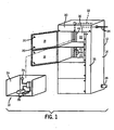
FIG. 1 is a perspective view of an exemplary packaged electrical system, such as an MCC, incorporating a connector arrangement in accordance with aspects of the invention; -
FIG. 2 is a detailed view of the prewired connector assembly installed in the enclosure ofFIG. 1 ; -
FIG. 3 is a detailed perspective view of a component connector assembly installed on a rear panel of a component support; -
FIG. 4 is side perspective view of the connector assemblies ofFIGS. 2 and3 prior to mating; -
FIG. 5 is a similar side view of the connector assemblies at the point of full engagement of the component support within the enclosure to force mating of the connector assemblies; -
FIG. 6 is a similar side perspective view of the connector assemblies positioned at a limit of the range of movement of the component connector assembly with respect to the prewired connector assembly; -
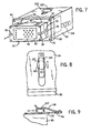
FIG. 7 is a perspective view of an alternative connector configuration for use in a component support including a single connector assembly; -
FIG. 8 is a partial top view of the connector arrangement ofFIG. 7 ; -
FIG. 9 is a partial side view of the connector arrangement ofFIG. 8 ; and -
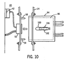
FIG. 10 is a partial top view of the connector ofFIG. 7 aligned for mating with a connector in a power, in a network and control power wireway. - Turning now to the drawings, and referring first to
FIG. 1 , a packagedelectrical system 10 is illustrated as including anenclosure 12 that houses various electrical components. The enclosure will typically be formed of heavy gage sheet metal, although other enclosures, such as made of reinforced plastic may sometimes be used. The enclosure generally forms ashell 14 having a maininterior volume 16 in which components and component supports are placed. Theinterior volume 16 may be subdivided into compartments that each receive particular components, typically components interconnected to form a portion of the overall process control or monitoring system. Each compartment may be accessed throughmain doors 18.Latches 20 are provided to hold the doors closed over the interior volume during operation. - Within each of the compartments, designated generally by reference numeral 22 in
FIG. 1 ,component supports 24 may be disposed. As will be appreciated by those skilled in the art, the component supports 24 may be configured in various standard sizes or heights, and will typically comprise a metal drawer that can be slid into a compartment designed to accommodate the particular component support. On or within the component supports 24, a variety ofcomponents 26 are supported and interconnected. As noted above, such components may include electronic devices, such as programmable logic controllers, power electronic devices, such as motor controllers, inverter drives, and so forth, as well as switchgear, input/output interfaces, protective circuit components, and so forth. The components are generally designed to perform some control or monitoring function within an overall machine system. Accordingly, data signals are exchanged with the components and remote control and monitoring equipment or computers (not shown). Power signals are also provided to the components, as described in greater detail below, for enabling energization of such components such as relays, contactors, and so forth. Similarly, three phase power is typically provided to those components which will provide power to driven loads. Such loads may include motors, actuators, valves, and any other electrical load that may be present in the controlled or monitored process. - Within each
component support 24, acomponent connector assembly 28 is supported. In the illustrated embodiment, thecomponent connector assembly 28 is disposed on a rear wall of the support. As will be appreciated by those skilled in the art, such component connector assemblies may be provided on any suitable surface or support of the component support, such as a side panel, a lower or upper corner, and so forth. As described in greater detail below, thecomponent connector assembly 28 will mate with a prewired connector assembly within the enclosure to provide network signals and control power to the components within the component support. - The
enclosure 12 is particularly configured to pass network signals and control power through routing pads separated from other paths for main or three phase power. In the embodiment illustrated inFIG. 1 , for example, an upper wireway orsection 30 of the enclosure accommodates anetwork trunk cable 32 as well as conductors or cabling for control power, as indicated by reference numeral 34. The network trunk cable may be a shielded or flat media cable or any other suitable cable that is capable of transmitting data signals between the components and remote circuitry in accordance with standard network protocols. An exemplary protocol for MCCs, for example, is the DeviceNet protocol. The control power supplied by conductors 34 may be provided at various levels, depending upon the application. The conductors may be particularly configured, for example, to carry 110, 115, 220, or 230 volt, single phase power, 24 volt direct current power, 24 volt single phase power, and so forth. - A
separate wireway 36 is provided in the enclosure for routing three phase power. In many applications, such power will be rated at 460 volt three phase, and may be provided in either three-wire configurations or four-wire configurations (including a neutral conductor). Such wiring will be routed through amain conduit 38 and connected within the backplane of the enclosure to main bus bars that are engaged by the component supports by conventional stab connections (not shown). - The embodiment shown in
FIG. 1 provides a separate network and controlpower wireway 40 isolated from themain power wireway 36. Because of the lower power levels that would typically be present in thenetwork conductor 32 and control power conductors 34, it has been found desirable to separate these wireways for initial installation and subsequent servicing needs. Accordingly, anetwork cable 42 is provided in the network and controlpower wireway 40, and is electrically coupled to conductors within thetrunk cable assembly 32. Similar drop conductors (not shown) are provided for conductors coupled to the control power conductors 34. Where multiple sections or bays are provided in the system, the networktrunk cable assembly 32 and the control power conductors 34 may continue through similar wireways to such additional bays or enclosures.Tabs 44 are provided in the network and controlpower wireway 40 for accommodating prewired connector assemblies that mate withconnector assembly 28 as described in greater detail below. -
FIG. 2 represents a detailed view of the rear wall of the enclosure ofFIG. 1 , showing the network and control wireway formed in arear panel 46 of the enclosure. As shown inFIG. 2 , the wireway may be at least partially covered byblind plates 48 that enclose the wireway and are secured in place via appropriate fasteners totabs 44. At the location of acomponent connector assembly 28 of a component support (see,FIG. 1 ), a prewiredconnector assembly 50 will be provided and similarly secured to the tabs of the wireway. Each prewired connector assembly generally includes aplate 52 on or through which amating network connector 54 and acontrol power connector 56 are mounted.Connectors mating network connector 54 includes an orientation-sensitive receptacle having four conductors, two for data signals and two for network power. The matingcontrol power connector 56 is also a commercially available connector including multiple conductors in an orientation-sensitive body for conveying the appropriate level of control power (e.g., 110 or 115 volt single phase power, 24 volt direct current power, and so forth). Theplate 52 also supports one or more alignment devices, such as alignment pins 58 in the illustrated embodiment. These alignment devices aid in aligning themating connectors -
FIG. 3 illustrates an exemplarycomponent connector assembly 28 of the type that can be interfaced with the prewiredconnector assembly 50 ofFIG. 2 . In the particular implementation illustrated inFIG. 3 , thecomponent connector assembly 28 is mounted on a rear panel or wall 60 of thecomponent support 24. A fixedbase plate 62 is firmly secured to the rear wall, and connected to aconnector support plate 64 that is movable with respect to the base plate. Control ordisengagement members 66 extend through thebase plate 62 and are fixed (e.g., threaded) to theconnector support plate 64 to force disengagement of the connectors as described in greater detail below. The plates include apertures or recesses 68 to accommodate the alignment pins 58 (see,FIG. 2 ) of the mating network connector to facilitate alignment of the connectors during engagement. - In the embodiment illustrated in
FIG. 3 , a pair of separate connectors are supported on theconnector support plate 64. These include anetwork connector 70 designed to mate with themating network connector 54 shown inFIG. 2 .Plate 64 also supports acontrol power connector 72 specifically designed to mate withconnector 56 shown inFIG. 2 . - The connectors supported on the network and control power wireway and on the component support mate as illustrated in
FIG. 4 . As shown inFIG. 4 , the prewiredconnector assembly 50 generally includes anetwork connector body 74 the connector face of which is themating network connector 54. In the illustrated embodiment, thenetwork connector body 74 makes contact with conductors in thenetwork cable 42 via insulation displacement ("vampire") pins (not shown). Other termination arrangements may, of course, be used. - On the left-hand side of
FIG. 4 , thecomponent connector assembly 28 is illustrated, removed from the component support for the sake of clarity. Theconnector assembly 28 includes both thenetwork connector 70 and thecontrol power connector 72 that are coupled to wiring orcables 80 that extend throughapertures base plate 62. Similar apertures will be provided in the rear panel of the component support to permit the passage of thecables 80. Theconnector support plate 64 withconnectors springs 76. Thus, the springs hold theconnector support plate 64 in a normal or operative position, but the combination of the springs and of thecontrol rods 66 allow for movement of the connector support plate (andconnectors 70 and 72) with respect to the rear panel of the component support. -
FIG. 5 illustrates the configuration of the connectors at the time of installation and full engagement of a component support. As can be seen inFIG. 5 , thesprings 76 are compressed around thecontrol rods 66, which are allowed to extend rearwardly through thebase plate 62. The cables connected toconnectors connectors respective connectors -
FIG. 6 illustrates the mated connector assemblies in a retracted position of the component support (not shown inFIG. 6 for the sake of clarity). Again, thebase plate 62 of the component connector assembly is secured to the component support such that as the component support is partially withdrawn from the enclosure, thebase plate 62 slides with respect to thecontrol rods 66. At a maximum point of withdrawal, effectively the limit of the range provided by the length ofcontrol rods 66, thebase plate 62 will contact the heads of thecontrol rods 66 and force disengagement of the connectors from one another. The range of movement provided in thecomponent connector assembly 28 will depend essentially upon the distance desired for uncoupling main power from the component support (via withdrawal of stabs from power buses). - As will be noted by those skilled in the art, once the connector assembly is described above are mated, contact between the connector assemblies is static. That is, no sliding contact takes place during either operation or during partial withdrawal for servicing of the component support from the enclosure. It has been found that such non-sliding contact between the connectors facilitates good signal transmission and avoids problems with signal degradation present in conventional sliding contacts for such applications.
- The foregoing arrangement allows for coupling of a component support to a connector for control power and network signals within a separated wireway using a connector assembly including more than one connector. An alternative configuration including a single connector is illustrated in
FIG. 7 . Although may such arrangements may be envisaged, thealternative connector assembly 82 ofFIG. 7 includes astationary part 84 designed to be affixed to the rear panel of a component support, and amovable part 86. Thestationary part 84 has a flange 88 withfastener holes 90 designed to receive fasteners for fixing the stationary part on the rear panel (not shown inFIG. 7 ) of a component support.Guides 92 are formed on themovable part 86 to aid in guiding the movable part as it is slid within the stationary part. Theguides 92 interface withrecesses 94 for this purpose. Themovable part 86 comprises amulti-pin plug 96 including either male, female or both types of engagement members for transmitting data signals to and from components within the component support, and for transmitting control power to the components. In the embodiment illustrated inFIG. 7 , fore and aft movement of themovable part 86 is limited by a travel-limitingslot 100 in which astop bolt 102 is positioned. Thestop bolt 102 may be a shoulder fastener, for example, that is fitted to themovable part 86 throughslot 100. Within the assembly, one or more biasing springs, indicated generally byreference numeral 104, serve to urge the movable part towards the operative or engaged position. - Where desired, an additional biasing member represented in
FIGS. 8 and 9 may be included for interfacing with themovable part 86. In the illustrated embodiment, aspring member 106 is provided that has a contour designed to interface with the head of thestop bolt 102. That is, in either the fully or near-fully retracted position or the fully or near-fully extended position, thespring member 106 generally causes a biasing force to be applied to themovable part 86 that can be overcome to allow the movable part to be slid into or out of thestationary part 84. -
FIG. 10 illustrates the alternative arrangement immediately prior to making of the connections. As shown inFIG. 10 , themovable part 86 of thealternative connector assembly 82 will generally be recessed within thestationary part 84. Thestationary part 84 is, as noted above, secured to the rear panel of a component support as indicated byreference numeral 24. In the stop bolt arrangement of the illustrated embodiment, the bolt will bear against a rear surface of the travel-limitingslot 100. As the connector assembly approaches the prewiredconnector assembly 50 provided within the network and controlpower wireway 40, alignment pins 58 engage corresponding holes 98 (seeFIG. 7 ) to align the connectors with one another. Further engagement of the component support within the enclosure, then, causes the connectors to be mated. Thereafter, partial retraction of the component support is possible while maintaining a static (non-sliding) connection between the mated connectors. The degree to which the component support can be withdrawn from the enclosure is, in the illustrated embodiment, defined by the length of the travel-limitingslot 100. - While only certain features of the invention have been illustrated and described herein, many modifications and changes will occur to those skilled in the art. It is, therefore, to be understood that the appended claims are intended to cover all such modifications and changes as fall within the true spirit of the invention.
The following is a list of further preferred embodiments of the invention: - Embodiment 1: An electrical power control system (10) comprising:
- an enclosure (12) for housing an electrical power component support;
- a prewired connector assembly (50) disposed in the enclosure (12) and configured to receive data signals from a network and control power from a power source; and
- a component support (24) disposed in the enclosure (12), the support (24) having a component connector assembly (28, 82) supported thereon matable with the prewired connector assembly (50) to provide the data signals and control power to components (26) supported by the support;
- wherein at least one of the prewired connector assembly (50) and the component connector assembly (28, 82) is biased towards a normal position and movable within a predetermined range to maintain a non-sliding contact between the connector assemblies (28, 82, 50) during displacement of the component support (24) in the enclosure (12).
- Embodiment 2: The system of embodiment 1, wherein the component connector assembly (28, 82) includes a base (62, 84) fixed to the component support (24) and a movable assembly (64, 86) secured to but movable with respect to the base (62, 84), the movable assembly (64, 86) being matable with the prewired connector assembly (50).
- Embodiment 3: The system of
embodiment 2, wherein the movable assembly (64, 86) is secured to the base (62, 84) via at least one disengagement member (66), the disengagement member (66) causing the movable assembly (64, 86) to be unmated from the prewired connector assembly (50) when the support is displaced beyond the predetermined range. - Embodiment 4: The system of
embodiment 2, wherein the disengagement member (66) includes at least one rod extending between the base (62, 84) and the movable assembly (64, 86) for causing the movable assembly (64, 86) to be unmated from the prewired connector assembly (50). - Embodiment 5: The system of embodiment 4, further comprising a biasing spring (76, 104) disposed around the at least one rod between the base (62, 84) and the movable assembly (64, 86), the biasing spring (76, 104) urging the movable assembly (64, 86) towards the normal position.
- Embodiment 6: The system of
embodiment 2, wherein the base (62, 84) and the movable assembly (64, 86) cooperate to force mating of the movable assembly (64, 86) with the prewired connector assembly (50) when the support is fully engaged into an operating position within the enclosure (12). - Embodiment 7: The system of embodiment 1, wherein each of the prewired connector assembly (50) and the component connector assembly (28, 82) includes a plurality of connectors (54, 56, 70, 72, 96).
- Embodiment 8: The system of embodiment 7, wherein the plurality of connectors includes separate network (54, 70, 96) and control power connectors (56, 72, 96).
- Embodiment 9: :n electrical power control system (10) comprising:
- an enclosure (12) for housing electrical power component supports;
- a plurality of prewired connector assemblies (50) disposed in the enclosure (12) and configured to receive data signals from a network and control power from a power source; and
- a plurality of component supports (24) disposed in the enclosure (12), each of the supports (24) having a component connector assembly (28, 82) supported thereon matable with a prewired connector assembly (50) to provide the data signals and control power to components (26) supported by the support (24), wherein each of the component connector assemblies (28, 82) is biased towards a normal position and movable within a predetermined range to maintain a non-sliding contact between the component connector assembly (28, 82) and the respective prewired connector assembly (50) during displacement of the respective component support (24) in the enclosure (12).
- Embodiment 10: The system of embodiment 9, wherein the enclosure (12) includes a power wireway (36) for housing three phase power conductors, and wherein the prewired connector assemblies (50) are disposed over a wireway (40) separate from the power wireway (36).
- Embodiment 11: The system of embodiment 9, wherein each of the component connector (28, 82) includes a base (62, 84) fixed to the respective component support (24) and a movable assembly (64, 86) secured to but movable with respect to the base (62, 84), the movable assembly (64, 86) being matable with the respective prewired connector assembly (50).
- Embodiment 12: The system of embodiment 11, wherein the movable assembly (64, 86) of each component connector assembly (28, 82) is secured to the base (62, 84) via at least one disengagement member (66), the disengagement member (66) causing the movable assembly (64, 86) to be unmated from the prewired connector assembly (50) when the support (24) is displaced beyond the predetermined range.
- Embodiment 13: The system of embodiment 11, wherein the disengagement member (66) includes at least one rod extending between the base (62, 84) and the movable assembly (64, 86) for causing the movable assembly (64, 86) to be unmated from the respective prewired connector assembly (50).
- Embodiment 14: The system of embodiment 13, wherein each component connector assembly (28, 82) further includes a biasing spring (76, 104) disposed around the at least one rod between the base (62, 84) and the movable assembly (64, 86), the biasing spring (76, 104) urging the movable assembly (64, 86) towards the normal position.
- Embodiment 15: The system of embodiment 11, wherein the base (62, 84) and the movable assembly (64, 86) of each component connector assembly (28, 82) cooperate to force mating of the movable assembly (64, 86) with the prewired connector assembly (50) when the support (24) is fully engaged into an operating position within the enclosure (12).
- Embodiment 16: The system of embodiment 9, wherein each of the prewired connector assemblies (50) and each of the component connector assemblies (28, 82) includes a plurality of connectors (54, 56, 70, 72, 96).
- Embodiment 17: An electrical power control system (10) comprising:
- an enclosure (12) for housing electrical power component supports;
- a plurality of prewired connector assemblies (50) disposed in the enclosure (12) adjacent to a network and control power wireway (40) and configured to receive data signals from a network and control power from a power source;
- a power wireway (36) within the enclosure (12) and separated from the network and control power wireway (40) for housing three phase power conductors; and
- a plurality of component supports (24) disposed in the enclosure (12), each of the supports having a component connector assembly (28, 82) supported thereon matable with a prewired connector assembly (50) to provide the data signals and control power to components (26) supported by the support (24), wherein each of the component connector assemblies (28, 82) is biased towards a normal position and movable within a predetermined range to maintain a non-sliding contact between the component connector assembly (28, 82) and the respective prewired connector assembly (50) during displacement of the respective component support (24) in the enclosure (12).
- Embodiment 18: The system of embodiment 17, wherein each of the component connector assemblies (28, 82) includes a base (62, 84) fixed to the respective component support (24) and a movable assembly (64, 86) secured to but movable with respect to the base (62, 84), the movable assembly (64, 86) being matable with the respective prewired connector assembly (50).
- Embodiment 19: The system of embodiment 17, wherein the movable assembly (64, 86) of each component connector assembly (28, 82) is secured to the base (62, 84) via at least one disengagement member (66), the disengagement member (66) causing the movable assembly (64, 86) to be unmated from the prewired connector assembly (50) when the support (24) is displaced beyond the predetermined range.
- Embodiment 20: The system of embodiment 17, wherein each of the prewired connector assemblies (50) and each of the component connector assemblies (28, 82) includes a plurality of connectors (52, 54, 70, 72, 96).
Claims (14)
- An electrical power control system (10) comprising:an enclosure (12) for housing an electrical power component support;a prewired connector assembly (50) disposed in the enclosure (12) and configured to receive data signals from a network and control power from a power source; anda component support (24) disposed in the enclosure (12), the support (24) having a component connector assembly (28, 82) supported thereon matable with the prewired connector assembly (50) to provide the data signals and control power to components (26) supported by the support;wherein at least one of the prewired connector assembly (50) and the component connector assembly (28, 82) is biased towards a normal position and movable within a predetermined range to maintain a non-sliding contact between the connector assemblies (28, 82, 50) during displacement of the component support (24) in the enclosure (12).
- An electrical power control system (10) comprising:an enclosure (12) for housing electrical power component supports;a plurality of prewired connector assemblies (50) disposed in the enclosure (12) and configured to receive data signals from a network and control power from a power source; anda plurality of component supports (24) disposed in the enclosure (12), each of the supports (24) having a component connector assembly (28, 82) supported thereon matable with a prewired connector assembly (50) to provide the data signals and control power to components (26) supported by the support (24), wherein each of the component connector assemblies (28, 82) is biased towards a normal position and movable within a predetermined range to maintain a non-sliding contact between the component connector assembly (28, 82) and the respective prewired connector assembly (50) during displacement of the respective component support (24) in the enclosure (12).
- The system of claim 2, wherein the enclosure (12) includes a power wireway (36) for housing three phase power conductors, and wherein the prewired connector assemblies (50) are disposed over a wireway (40) separate from the power wireway (36).
- The system of claim 1 or 2, wherein the or each of the component connector assembly (28, 82) includes a base (62, 84) fixed to the respective component support (24) and a movable assembly (64, 86) secured to but movable with respect to the base (62, 84), the movable assembly (64, 86) being matable with the respective prewired connector assembly (50).
- The system of claim 1, 2 or 4, wherein the movable assembly (64, 86) of the or each component connector assembly (28, 82) is secured to the base (62, 84) via at least one disengagement member (66), the disengagement member (66) causing the movable assembly (64, 86) to be unmated from the prewired connector assembly (50) when the support (24) is displaced beyond the predetermined range.
- The system of claim 1, 2 or 4, wherein the disengagement member (66) includes at least one rod extending between the base (62, 84) and the movable assembly (64, 86) for causing the movable assembly (64, 86) to be unmated from the respective prewired connector assembly (50).
- The system of claim 6, wherein the or each component connector assembly (28, 82) further includes a biasing spring (76, 104) disposed around the at least one rod between the base (62, 84) and the movable assembly (64, 86), the biasing spring (76, 104) urging the movable assembly (64, 86) towards the normal position.
- The system of claim 1, 2 or 4, wherein the base (62, 84) and the movable assembly (64, 86) of the or each component connector assembly (28, 82) cooperate to force mating of the movable assembly (64, 86) with the prewired connector assembly (50) when the support (24) is fully engaged into an operating position within the enclosure (12).
- The system of claim 1 or 2, wherein each of the prewired connector assemblies (50) and the or each component connector assembly (28, 82) includes a plurality of connectors (54, 56, 70, 72, 96).
- The system of claim 9, wherein the plurality of connectors includes separate network (54, 70, 96) and control power connectors (56, 72, 96).
- An electrical power control system (10) comprising:an enclosure (12) for housing electrical power component supports;a plurality of prewired connector assemblies (50) disposed in the enclosure (12) adjacent to a network and control power wireway (40) and configured to receive data signals from a network and control power from a power source;a power wireway (36) within the enclosure (12) and separated from the network and control power wireway (40) for housing three phase power conductors; anda plurality of component supports (24) disposed in the enclosure (12), each of the supports having a component connector assembly (28, 82) supported thereon matable with a prewired connector assembly (50) to provide the data signals and control power to components (26) supported by the support (24), wherein each of the component connector assemblies (28, 82) is biased towards a normal position and movable within a predetermined range to maintain a non-sliding contact between the component connector assembly (28, 82) and the respective prewired connector assembly (50) during displacement of the respective component support (24) in the enclosure (12).
- The system of claim 11, wherein each of the component connector assemblies (28, 82) includes a base (62, 84) fixed to the respective component support (24) and a movable assembly (64, 86) secured to but movable with respect to the base (62, 84), the movable assembly (64, 86) being matable with the respective prewired connector assembly (50).
- The system of claim 12, wherein the movable assembly (64, 86) of each component connector assembly (28, 82) is secured to the base (62, 84) via at least one disengagement member (66), the disengagement member (66) causing the movable assembly (64, 86) to be unmated from the prewired connector assembly (50) when the support (24) is displaced beyond the predetermined range.
- The system of claim 11, wherein each of the prewired connector assemblies (50) and each of the component connector assemblies (28, 82) includes a plurality of connectors (52, 54, 70, 72, 96).
Applications Claiming Priority (3)
| Application Number | Priority Date | Filing Date | Title |
|---|---|---|---|
| US11/271,713 US7419394B2 (en) | 2005-11-11 | 2005-11-11 | Electrical system having withdrawable unit with maintained control and communication connection |
| EP06827154A EP1952681B1 (en) | 2005-11-11 | 2006-10-31 | Electrical system having withdrawable unit with maintained control and communication connection |
| PCT/US2006/042446 WO2007058766A2 (en) | 2005-11-11 | 2006-10-31 | Electrical system having withdrawable unit with maintained control and communication connection |
Related Parent Applications (2)
| Application Number | Title | Priority Date | Filing Date |
|---|---|---|---|
| EP06827154A Division EP1952681B1 (en) | 2005-11-11 | 2006-10-31 | Electrical system having withdrawable unit with maintained control and communication connection |
| EP06827154.3 Division | 2006-10-31 |
Publications (2)
| Publication Number | Publication Date |
|---|---|
| EP2276332A1 true EP2276332A1 (en) | 2011-01-19 |
| EP2276332B1 EP2276332B1 (en) | 2019-07-17 |
Family
ID=37950600
Family Applications (2)
| Application Number | Title | Priority Date | Filing Date |
|---|---|---|---|
| EP06827154A Ceased EP1952681B1 (en) | 2005-11-11 | 2006-10-31 | Electrical system having withdrawable unit with maintained control and communication connection |
| EP10012834.7A Ceased EP2276332B1 (en) | 2005-11-11 | 2006-10-31 | Electrical system having withdrawable unit with maintained control and communication connection |
Family Applications Before (1)
| Application Number | Title | Priority Date | Filing Date |
|---|---|---|---|
| EP06827154A Ceased EP1952681B1 (en) | 2005-11-11 | 2006-10-31 | Electrical system having withdrawable unit with maintained control and communication connection |
Country Status (5)
| Country | Link |
|---|---|
| US (1) | US7419394B2 (en) |
| EP (2) | EP1952681B1 (en) |
| CN (1) | CN201374888Y (en) |
| DE (1) | DE602006018781D1 (en) |
| WO (1) | WO2007058766A2 (en) |
Families Citing this family (49)
| Publication number | Priority date | Publication date | Assignee | Title |
|---|---|---|---|---|
| US10973143B2 (en) | 2006-07-26 | 2021-04-06 | Eaton Intelligent Power Limited | Coordinating installation and connection of a motor control center subunit having moveable line contacts |
| US8817454B2 (en) * | 2006-07-26 | 2014-08-26 | Eaton Corporation | Coordinating installation and connection of a motor control center subunit having moveable line contacts |
| US7688572B2 (en) | 2006-07-26 | 2010-03-30 | Eaton Corporation | Motor control center subunit having moveable line contacts and method of manufacture |
| US7684201B2 (en) * | 2007-06-01 | 2010-03-23 | Dell Products, Lp | Multi-stage alignment guidepin |
| DE102007030344B4 (en) * | 2007-06-29 | 2009-10-15 | Andreas Siemes | Device for controlling a soft start or run-down of three-phase motors, - so-called soft starters |
| US20090257174A1 (en) * | 2008-04-15 | 2009-10-15 | Mahesh Jaywant Rane | Self-disengaging contacts for secondary circuits of draw-out type circuit breakers |
| DK200901311A (en) * | 2009-01-22 | 2010-02-10 | Andersen Keld Gade | Fire detection apparatus and method |
| US7965493B2 (en) * | 2009-08-05 | 2011-06-21 | Eaton Corporation | Motor control center and subunit therefor |
| FR2951031B1 (en) | 2009-10-06 | 2011-10-28 | Schneider Electric Ind Sas | FUNCTIONAL UNIT FOR LOW VOLTAGE CHART WITH TEST POSITION |
| US8638561B2 (en) | 2009-11-06 | 2014-01-28 | Rockwell Automation Technologies, Inc. | Motor control center unit withdraw with door closed |
| EP2388865A1 (en) | 2010-05-18 | 2011-11-23 | Eaton Industries (Netherlands) B.V. | Connection assembly for electrical cabinet |
| DE102010039934B4 (en) * | 2010-08-30 | 2017-02-02 | Siemens Aktiengesellschaft | Recording module for receiving a circuit breaker, circuit breaker system and method for coupling a power switch with a receiving module |
| US8274782B2 (en) | 2010-09-30 | 2012-09-25 | Rockwell Automation Technologies, Inc. | Motor control center network connectivity method and system |
| US8810998B2 (en) * | 2012-04-23 | 2014-08-19 | Eaton Corporation | Motor control center and communication system therefor |
| US8748760B2 (en) * | 2012-06-19 | 2014-06-10 | Rockwell Automation Technologies, Inc. | Linear actuating earthing switch |
| US8988860B2 (en) * | 2012-11-29 | 2015-03-24 | Siemens Aktiengesellschaft | Power supplies having power electronic modules and replacement methods thereof |
| US8992241B2 (en) | 2013-04-30 | 2015-03-31 | International Business Machines Corporation | Flex circuit blind attachment apparatus and system |
| US9297494B1 (en) * | 2013-08-28 | 2016-03-29 | The Boeing Company | Dagger pin interface apparatus with swivel pin |
| US9831645B2 (en) | 2013-09-25 | 2017-11-28 | Schneider Electric USA, Inc. | Spring loaded, bistable connect/disconnect for MCC unit |
| CA2921497C (en) | 2013-09-27 | 2020-09-15 | Schneider Electric USA, Inc. | Motor control center unit disconnect with interlocks |
| WO2015047375A1 (en) * | 2013-09-30 | 2015-04-02 | Schneider Electric USA, Inc. | Mcc unit troubleshooting compartment |
| TWI507852B (en) * | 2013-10-29 | 2015-11-11 | Wistron Corp | Docking station and electronic apparatus |
| WO2015147824A1 (en) | 2014-03-27 | 2015-10-01 | Schneider Electric USA, Inc. | Knife blade switch contact with high resistance portion |
| US9444234B2 (en) * | 2014-05-28 | 2016-09-13 | General Electric Company | Switchgear including a withdrawable switchgear unit having a blocking mechanism |
| US9748024B2 (en) * | 2014-06-20 | 2017-08-29 | Schneider Electric USA, Inc. | Passive arc control with sequestered phases in a vertical bus system of a motor control center |
| US9722399B2 (en) * | 2014-11-13 | 2017-08-01 | Westinghouse Electric Company, Llc | Electrical system, and connection device and method of powering a switchgear bus in an electrical system |
| USD816198S1 (en) | 2015-01-28 | 2018-04-24 | Phononic, Inc. | Thermoelectric heat pump |
| FR3033673B1 (en) * | 2015-03-13 | 2018-11-16 | Thales | CONNECTOR FOR ELECTRONIC EQUIPMENT ON BOARD WITH TWO CONNECTORS |
| US9948073B2 (en) * | 2015-04-27 | 2018-04-17 | Abb Schweiz Ag | Auxiliary compartment for a switchgear system |
| US9460881B1 (en) * | 2015-04-30 | 2016-10-04 | Eaton Corporation | Compact plug and socket unit isolator systems for motor control centers (MCC) and related MCC cabinets |
| KR200486227Y1 (en) * | 2016-03-16 | 2018-04-17 | 엘에스산전 주식회사 | Motor control center unit |
| US9941674B1 (en) * | 2016-12-09 | 2018-04-10 | General Electric Company | Systems for motor control center buckets |
| EP3404421B1 (en) * | 2017-05-15 | 2024-09-25 | Eppendorf SE | Laboratory instrument and insertable network instrument |
| GB2562737B (en) * | 2017-05-23 | 2020-06-10 | Ge Aviat Systems Ltd | Power management panel and controller assembly |
| USD833588S1 (en) * | 2017-10-11 | 2018-11-13 | Phononic, Inc. | Thermoelectric heat pump |
| US10601204B2 (en) | 2018-02-09 | 2020-03-24 | Rockwell Automation Technologies, Inc. | Electrical unit for a motor control center with ingress protection |
| WO2019192690A1 (en) * | 2018-04-04 | 2019-10-10 | Abb Schweiz Ag | Arrangement comprising a compartment and a slide-in module |
| WO2019192689A1 (en) * | 2018-04-04 | 2019-10-10 | Abb Schweiz Ag | Compartment for a withdrawable module |
| CN111869023A (en) * | 2018-04-05 | 2020-10-30 | Abb瑞士股份有限公司 | Switchgear modules installed in switchgear cabinets and switchgear cabinets comprising such switchgear modules |
| US10439371B1 (en) | 2018-06-22 | 2019-10-08 | Schneider Electric USA, Inc. | Snapped in rotating arc housing assembly for safety switch |
| US10541519B1 (en) * | 2018-10-10 | 2020-01-21 | Hamilton Sundstrand Corporation | Large current circuit breaker plug-in installation |
| US11417989B2 (en) * | 2020-03-12 | 2022-08-16 | Koninklijke Fabriek Inventum B.V. | Galley insert power connector assembly with spring assemblies |
| US12249821B2 (en) * | 2020-07-24 | 2025-03-11 | Schneider Electric USA, Inc. | Plug-on service-entrance neutral device |
| KR102506782B1 (en) * | 2021-04-13 | 2023-03-06 | 엘에스일렉트릭(주) | Moving apparatus and circuit breaker including the same |
| FR3127083B1 (en) * | 2021-09-16 | 2024-07-26 | Psa Automobiles Sa | CONDUCTIVE BARS FOR VEHICLE |
| US20230132464A1 (en) * | 2021-10-28 | 2023-05-04 | Nuro, Inc. | Methods and apparatus for supporting compartment inserts with interface arrangements in autonomous delivery vehicles |
| CN114779892B (en) * | 2022-03-18 | 2023-09-05 | 西安外事学院 | Electronic computer with protective casing |
| TWM634629U (en) * | 2022-08-09 | 2022-11-21 | 和碩聯合科技股份有限公司 | Connecting device |
| WO2024137769A1 (en) * | 2022-12-20 | 2024-06-27 | Ppc Broadband, Inc. | Mounting bracket assembly structurally configured to mount optical fiber management components, including different size communication devices, in an enclosure |
Citations (3)
| Publication number | Priority date | Publication date | Assignee | Title |
|---|---|---|---|---|
| US5344332A (en) * | 1993-06-03 | 1994-09-06 | Storage Technology Corporation | Apparatus and method for floatable electrical connection of semi-rigidly mounted devices |
| US20020081881A1 (en) * | 2000-12-22 | 2002-06-27 | Komenda Vernon A. | Spring-loaded connector setup for blind mating and method for using the same |
| EP1521511A2 (en) * | 2003-09-30 | 2005-04-06 | Rockwell Automation Technologies, Inc. | Motor control center interconnection method and apparatus |
Family Cites Families (2)
| Publication number | Priority date | Publication date | Assignee | Title |
|---|---|---|---|---|
| US4967311A (en) * | 1987-07-22 | 1990-10-30 | Tandem Computers Incorporated | Electronic module interconnection system |
| DOP2000000107A (en) * | 1999-12-01 | 2002-09-16 | Agouron Pharmaceutical Inc | COMPOUNDS, COMPOSITIONS AND METHODS TO STIMULATE THE GROWTH AND LENGTH OF NEURONS |
-
2005
- 2005-11-11 US US11/271,713 patent/US7419394B2/en not_active Expired - Lifetime
-
2006
- 2006-10-31 CN CN200690000088U patent/CN201374888Y/en not_active Expired - Lifetime
- 2006-10-31 EP EP06827154A patent/EP1952681B1/en not_active Ceased
- 2006-10-31 WO PCT/US2006/042446 patent/WO2007058766A2/en not_active Ceased
- 2006-10-31 DE DE602006018781T patent/DE602006018781D1/en active Active
- 2006-10-31 EP EP10012834.7A patent/EP2276332B1/en not_active Ceased
Patent Citations (3)
| Publication number | Priority date | Publication date | Assignee | Title |
|---|---|---|---|---|
| US5344332A (en) * | 1993-06-03 | 1994-09-06 | Storage Technology Corporation | Apparatus and method for floatable electrical connection of semi-rigidly mounted devices |
| US20020081881A1 (en) * | 2000-12-22 | 2002-06-27 | Komenda Vernon A. | Spring-loaded connector setup for blind mating and method for using the same |
| EP1521511A2 (en) * | 2003-09-30 | 2005-04-06 | Rockwell Automation Technologies, Inc. | Motor control center interconnection method and apparatus |
Also Published As
| Publication number | Publication date |
|---|---|
| US20070111575A1 (en) | 2007-05-17 |
| US7419394B2 (en) | 2008-09-02 |
| EP1952681A2 (en) | 2008-08-06 |
| EP1952681B1 (en) | 2010-12-08 |
| CN201374888Y (en) | 2009-12-30 |
| WO2007058766A3 (en) | 2007-11-15 |
| DE602006018781D1 (en) | 2011-01-20 |
| EP2276332B1 (en) | 2019-07-17 |
| WO2007058766A2 (en) | 2007-05-24 |
Similar Documents
| Publication | Publication Date | Title |
|---|---|---|
| US7419394B2 (en) | Electrical system having withdrawable unit with maintained control and communication connection | |
| US7525809B2 (en) | Isolated control and network wireway for motor control center | |
| US8638561B2 (en) | Motor control center unit withdraw with door closed | |
| US8553395B2 (en) | Motor control center network connectivity method and system | |
| EP1521511B1 (en) | Motor control center interconnection method and apparatus | |
| US9564707B2 (en) | Connection system with modular expansion units having two or more devices | |
| EP1786070B1 (en) | Multiple height, high density horizontal low voltage motor control center | |
| EP2693573A2 (en) | Power circuit electrical connection system and method | |
| EP3235103B1 (en) | Modular uninterruptible power supply and power distribution system | |
| EP0700756A1 (en) | Control device for industrial robots | |
| US8602816B2 (en) | Connector device for electronic modules in automation systems | |
| EP4580323A1 (en) | Network switch | |
| EP3525303A1 (en) | Electrical unit for a motor control center with ingress protection | |
| CN106575858B (en) | Motor control centers with automatic fusing of protective earths at the load terminals | |
| EP1427059B1 (en) | Device for connecting low-voltage devices | |
| US12206191B2 (en) | Blind electrical connection in a motor control center through spring contacts | |
| EP1753110A1 (en) | Modular power distribution apparatus and methods with protective earth conductor | |
| CN222896654U (en) | Switch base, AC contactor and charging pile | |
| CN105048198B (en) | A kind of input/output port, a kind of Train Control signal chassis and a kind of Train Control signal cabinet system | |
| US10141127B2 (en) | High-speed communications coupling for use in a circuit breaker assembly |
Legal Events
| Date | Code | Title | Description |
|---|---|---|---|
| PUAI | Public reference made under article 153(3) epc to a published international application that has entered the european phase |
Free format text: ORIGINAL CODE: 0009012 |
|
| AC | Divisional application: reference to earlier application |
Ref document number: 1952681 Country of ref document: EP Kind code of ref document: P |
|
| AK | Designated contracting states |
Kind code of ref document: A1 Designated state(s): DE FR GB |
|
| RIN1 | Information on inventor provided before grant (corrected) |
Inventor name: OMOTO, ARNALDO HIROYUKI Inventor name: MEYER, DEAN THOMAS Inventor name: MEIERS, RALPH E. Inventor name: BERGMANN, HERBERTO Inventor name: MALKOWSKI, CHESTER JR. |
|
| 17P | Request for examination filed |
Effective date: 20110719 |
|
| 17Q | First examination report despatched |
Effective date: 20110915 |
|
| GRAP | Despatch of communication of intention to grant a patent |
Free format text: ORIGINAL CODE: EPIDOSNIGR1 |
|
| INTG | Intention to grant announced |
Effective date: 20190304 |
|
| GRAS | Grant fee paid |
Free format text: ORIGINAL CODE: EPIDOSNIGR3 |
|
| GRAA | (expected) grant |
Free format text: ORIGINAL CODE: 0009210 |
|
| AC | Divisional application: reference to earlier application |
Ref document number: 1952681 Country of ref document: EP Kind code of ref document: P |
|
| AK | Designated contracting states |
Kind code of ref document: B1 Designated state(s): DE FR GB |
|
| REG | Reference to a national code |
Ref country code: GB Ref legal event code: FG4D |
|
| REG | Reference to a national code |
Ref country code: DE Ref legal event code: R096 Ref document number: 602006058333 Country of ref document: DE |
|
| REG | Reference to a national code |
Ref country code: DE Ref legal event code: R097 Ref document number: 602006058333 Country of ref document: DE |
|
| PLBE | No opposition filed within time limit |
Free format text: ORIGINAL CODE: 0009261 |
|
| STAA | Information on the status of an ep patent application or granted ep patent |
Free format text: STATUS: NO OPPOSITION FILED WITHIN TIME LIMIT |
|
| 26N | No opposition filed |
Effective date: 20200603 |
|
| P01 | Opt-out of the competence of the unified patent court (upc) registered |
Effective date: 20230404 |
|
| PGFP | Annual fee paid to national office [announced via postgrant information from national office to epo] |
Ref country code: GB Payment date: 20230920 Year of fee payment: 18 |
|
| PGFP | Annual fee paid to national office [announced via postgrant information from national office to epo] |
Ref country code: FR Payment date: 20230920 Year of fee payment: 18 |
|
| PGFP | Annual fee paid to national office [announced via postgrant information from national office to epo] |
Ref country code: DE Payment date: 20230920 Year of fee payment: 18 |
|
| REG | Reference to a national code |
Ref country code: DE Ref legal event code: R119 Ref document number: 602006058333 Country of ref document: DE |
|
| GBPC | Gb: european patent ceased through non-payment of renewal fee |
Effective date: 20241031 |
|
| PG25 | Lapsed in a contracting state [announced via postgrant information from national office to epo] |
Ref country code: DE Free format text: LAPSE BECAUSE OF NON-PAYMENT OF DUE FEES Effective date: 20250501 |
|
| PG25 | Lapsed in a contracting state [announced via postgrant information from national office to epo] |
Ref country code: GB Free format text: LAPSE BECAUSE OF NON-PAYMENT OF DUE FEES Effective date: 20241031 |
|
| PG25 | Lapsed in a contracting state [announced via postgrant information from national office to epo] |
Ref country code: FR Free format text: LAPSE BECAUSE OF NON-PAYMENT OF DUE FEES Effective date: 20241031 |