EP2276316A1 - Controller, wireless communication device, communication system and controlling method - Google Patents
Controller, wireless communication device, communication system and controlling method Download PDFInfo
- Publication number
- EP2276316A1 EP2276316A1 EP08752333A EP08752333A EP2276316A1 EP 2276316 A1 EP2276316 A1 EP 2276316A1 EP 08752333 A EP08752333 A EP 08752333A EP 08752333 A EP08752333 A EP 08752333A EP 2276316 A1 EP2276316 A1 EP 2276316A1
- Authority
- EP
- European Patent Office
- Prior art keywords
- data
- frame
- wireless communication
- sequence number
- mobile terminal
- Prior art date
- Legal status (The legal status is an assumption and is not a legal conclusion. Google has not performed a legal analysis and makes no representation as to the accuracy of the status listed.)
- Withdrawn
Links
Images






Classifications
-
- H—ELECTRICITY
- H04—ELECTRIC COMMUNICATION TECHNIQUE
- H04L—TRANSMISSION OF DIGITAL INFORMATION, e.g. TELEGRAPHIC COMMUNICATION
- H04L1/00—Arrangements for detecting or preventing errors in the information received
- H04L1/12—Arrangements for detecting or preventing errors in the information received by using return channel
- H04L1/16—Arrangements for detecting or preventing errors in the information received by using return channel in which the return channel carries supervisory signals, e.g. repetition request signals
- H04L1/18—Automatic repetition systems, e.g. Van Duuren systems
- H04L1/1867—Arrangements specially adapted for the transmitter end
- H04L1/1874—Buffer management
-
- H—ELECTRICITY
- H04—ELECTRIC COMMUNICATION TECHNIQUE
- H04L—TRANSMISSION OF DIGITAL INFORMATION, e.g. TELEGRAPHIC COMMUNICATION
- H04L1/00—Arrangements for detecting or preventing errors in the information received
- H04L1/12—Arrangements for detecting or preventing errors in the information received by using return channel
- H04L1/16—Arrangements for detecting or preventing errors in the information received by using return channel in which the return channel carries supervisory signals, e.g. repetition request signals
- H04L1/18—Automatic repetition systems, e.g. Van Duuren systems
- H04L1/1809—Selective-repeat protocols
-
- H—ELECTRICITY
- H04—ELECTRIC COMMUNICATION TECHNIQUE
- H04L—TRANSMISSION OF DIGITAL INFORMATION, e.g. TELEGRAPHIC COMMUNICATION
- H04L1/00—Arrangements for detecting or preventing errors in the information received
- H04L1/12—Arrangements for detecting or preventing errors in the information received by using return channel
- H04L1/16—Arrangements for detecting or preventing errors in the information received by using return channel in which the return channel carries supervisory signals, e.g. repetition request signals
- H04L1/18—Automatic repetition systems, e.g. Van Duuren systems
- H04L1/1829—Arrangements specially adapted for the receiver end
- H04L1/1835—Buffer management
-
- H—ELECTRICITY
- H04—ELECTRIC COMMUNICATION TECHNIQUE
- H04L—TRANSMISSION OF DIGITAL INFORMATION, e.g. TELEGRAPHIC COMMUNICATION
- H04L1/00—Arrangements for detecting or preventing errors in the information received
- H04L1/02—Arrangements for detecting or preventing errors in the information received by diversity reception
- H04L1/06—Arrangements for detecting or preventing errors in the information received by diversity reception using space diversity
-
- H—ELECTRICITY
- H04—ELECTRIC COMMUNICATION TECHNIQUE
- H04L—TRANSMISSION OF DIGITAL INFORMATION, e.g. TELEGRAPHIC COMMUNICATION
- H04L1/00—Arrangements for detecting or preventing errors in the information received
- H04L2001/0092—Error control systems characterised by the topology of the transmission link
- H04L2001/0093—Point-to-multipoint
-
- H—ELECTRICITY
- H04—ELECTRIC COMMUNICATION TECHNIQUE
- H04L—TRANSMISSION OF DIGITAL INFORMATION, e.g. TELEGRAPHIC COMMUNICATION
- H04L1/00—Arrangements for detecting or preventing errors in the information received
- H04L2001/0092—Error control systems characterised by the topology of the transmission link
- H04L2001/0097—Relays
-
- H—ELECTRICITY
- H04—ELECTRIC COMMUNICATION TECHNIQUE
- H04W—WIRELESS COMMUNICATION NETWORKS
- H04W92/00—Interfaces specially adapted for wireless communication networks
- H04W92/04—Interfaces between hierarchically different network devices
- H04W92/12—Interfaces between hierarchically different network devices between access points and access point controllers
Definitions
- the present invention relates to a communication system or the like having a wireless communication apparatus performing wireless communication with a mobile terminal device and a control apparatus for executing data communication with the mobile terminal device via the wireless communication apparatus.
- the HSUPA is a function of providing an access in an uplink direction of a larger band (direction from a terminal to a network) in a mobile communication system.
- FIG. 16 is a diagram illustrating the configuration of a conventional mobile communication system. As illustrated in the diagram, the mobile communication system has a mobile terminal (UE) 10, basestations (Node B) 20 to 22, Radio Network Controllers (RNCs) 30 and 31, and a Core Network (CN) 40.
- UE mobile terminal
- Node B basestations
- RNCs Radio Network Controllers
- CN Core Network
- the intervals between the CN 40, the RNCs 30 and 31 and the basestations 20 and 21 are wires intervals, and intervals between the basestations 20 to 22 and the mobile terminal 10 are wireless intervals.
- the interface between the mobile terminal and the basestation is called Uu
- the interface between the RNC and the basestation is called Iub
- the interface between the RNC and the RNC. is called Iur
- the interface between the CN and the RNC is called Iu.
- the user data when user data is received by the mobile terminal 10, the user data is transmitted to the RNC 30 accommodating the mobile terminal 10 via the CN 40.
- the RNC 30 transmits the user data to the basestation 20 accommodating the cell 1, and the basestation 20 transmits the user data to the mobile terminal.
- the user data transmitted from the mobile terminal 10 is received by any of the basestations 20 to 22, transmitted to the RNCs 30 and 31, and transmitted to the destination via the CN 40.
- FIG. 17 is a diagram for explaining a protocol model of the HSUPA
- FIG. 18 is a diagram illustrating outline of data communication (Iub/Iur boundary).
- a mobile terminal has layers of Application (APL), Radio Link Control (RLC; regarding RLC, refer to 3GPP TS25.322), Medium Access Control (MAC)-d, MAC-es, MAC-e, and physical layer (PHY), and a basestation has layers of MAC-e/Enhanced Dedicated Channel (EDCH) Frame Packet (FP) and PHY/TNL.
- APL Application
- RLC Radio Link Control
- MAC-d Medium Access Control
- MAC-es Medium Access Control
- MAC-e Medium Access Control
- PHY physical layer
- a basestation has layers of MAC-e/Enhanced Dedicated Channel (EDCH) Frame Packet (FP) and PHY/TNL.
- EDCH MAC-e/Enhanced Dedicated Channel
- FP Frame Packet
- the RNC has a D-RNL (relay device) and an S-RNC.
- the D-RNC has a layer TNL/TNL
- the S-RNC has layers APL, RLC, MAC-d, MAC-es, EDCH FP, and TNL.
- a data frame transmitted in the network direction (uplink direction) by the mobile terminal is divided in, short Packet Data Unit (PDU) by the function of the PLD/MAC-es layer. After that, some MAC-d PDUs are multiplexed, there by constructing an MAC-es PDU (refer to the first to third stages in FIG. 18 ).
- PDU Packet Data Unit
- TSN sequence number
- Some more MAC-es PDUs are further multiplexed at the time of transmission from the basestation to an S-RNC and transmitted on the EDCH FP unit basis (EDCH FP frame) onto the Iub. Also to the EDCH FP frame, the FSN as a sequence number is given (refer to the fourth stage in FIG. 18 ).
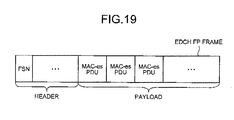
- FIG. 19 is a diagram illustrating an example of the data structure of the EDCH FP frame.
- the EDCH FP frame has header and payload, and the header has various control information (not illustrated) and the FSN.
- the payload has a plurality of Mac-es PDUs, and each MAC-es PDU has a TSN.
- the MAC-es PDU is extracted from the received EDCH FP frame, re-ordering is performed in accordance with the TSNs and, further, a process of reproducing a data frame is performed by terminating the MAC-d/RLC layer.
- transmission on the Iub/Iur is performed on the EDCH FP unit basis. Consequently, when a cause of frame drop such as congestion of a line occurs on the Iub/Iur, the unit of the drop also becomes the EDCH FP unit.
- the S-RNC has the function of detecting the drop by monitoring the FSN of the EDCH FP received, when drop is detected, regarding it as line congestion in the Iub/Iub, and notified the basestation of the congestion indication (TNL congestion indication).
- the basestation which receives the congestion notification from the RNC side has the function of suppressing data transmission to the Iub/Iur by a predetermined amount or a predetermined period.
- Patent Document 1 discloses a technique of improving throughput by waiting for an uplink retransmission packet only for predetermined time, transmitting a retransmission wait cancelling request to a wireless network control apparatus and, in the case where a retransmission wait cancellation response of instructing stop of retransmission waiting is received from the wireless network control apparatus, stopping the retransmission waiting.
- Patent Document 1 Japanese Laid-open Patent Publication No. 2006-86989
- the present invention is achieved to solve the problems of the conventional technique and an object of the invention is to provide a control apparatus, a wireless communication apparatus, a communication system, and a control method capable of improving use efficiency of a wireless band.
- the control apparatus requires a detecting unit that, when receiving data transmitted from a mobile terminal device via a wireless communication apparatus including a buffer that stores at least one of the data in a predetermined capacity and the data for a predetermined time, detects drop of the data on the basis of sequence numbers included in the data and associated with predetermined data; and a data obtaining unit that, when drop of data is detected by the detecting unit, transmits the sequence numbers corresponding to the dropped data to the wireless communication apparatus and obtains the dropped data from the buffer of the wireless communication apparatus.
- control apparatus in the case where drop of data occurs between the control apparatus and a basestation, by retransmitting data stored in the basestation, drop of the data is repaired. Consequently, an effect of improving use efficiency of the wireless band is obtained. Since the retransmission is performed without using the mobile terminal, the roundtrip can be made short.
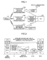
- FIG. 1 is a diagram for explaining the outline and characteristic of the mobile communication system according to the first embodiment.
- the mobile communication system has a mobile terminal 50, basestation 100a to 100c, and a Radio Network Controller (RNC) 200.
- RNC Radio Network Controller
- the intervals between the RNC 200 and the basestations 100a to 100c are wired intervals, and the intervals between the basestations 100a to 100c and the mobile terminal 50 are wireless intervals.
- the interface between the mobile terminal and the basestations will be called as Uu, and the interface between the RNC and the basestations will be called Iub/Iur.
- the mobile terminal 50 is an apparatus for executing transmission/reception of frames (frames include various control data, sound, images, data, and the like) to/from another mobile terminal (not illustrated) by using the mobile communication system.
- frames include various control data, sound, images, data, and the like
- the mobile terminal 50 assigns Transport Sequence Number (TSN) (refer to FIG. 18 ).
- TSN Transport Sequence Number
- the TSN is a sequence number indicative of the order of each frame. It is assumed that the TSN is given in the frame (MAC-es PDU) unit basis by the mobile terminal 50.
- the basestation 100a is an apparatus for relaying data communication executed between the mobile terminal 50 and the RNC 200.
- the basestation 100a generates an EDCH FP frame obtained by multiplexing frames and assigns Forward Sequence Number (FSN) to the generated EDCH FP frame.
- the FSN is a sequence number indicative of the order of the each FP frame.
- the basestation 100a transmits the generated EDCH FP frame to the RNC 200 and buffers the EDCH FP frame by a predetermined amount or for predetermined time. Since description on the basestations 100b and 100c is similar to the description on the basestation 100a.
- the RNC 200 is an apparatus for executing data communication with the mobile terminal 50 via the basestations 100a to 100c.
- the RNC 200 monitors the TSN included in the EDCH FP frame, and detects drop of the TSN.
- the RNC 200 transmits a control frame including the information of the TSN whose drop is detected to the basestations 100a to 100c.
- the basestations 100a to 100c which receive the control frame determine whether a frame corresponding to the TSN presents in the EDCH FP frames buffered. In the case where the frame presents, an EDCH FP frame including the TSN is retransmitted to the RNC 200.
- the basestation 100c in the case where a frame corresponding to the TSN exits in the basestation 100c, the basestation 100c retransmits an EDCH FP frame including the TSN to the RNC 200.
- FIG. 2 is a diagram illustrating processes at the time of retransmission of the conventional mobile communication system.
- FIG. 3 is a diagram illustrating processes at the time of retransmission of the mobile communication system of the invention.
- the drop of the frame is solved by the function of an RLC layer. Specifically, since drop is repaired by retransmission between the mobile terminal and the RNC, a problem occurs such that the band in the wireless interval (between the mobile terminal and the basestation) is wasted, and it causes increase in roundtrip time (throughput degradation).
- FIG. 4 is a functional block diagram illustrating the configuration of the basestation 100a and the RNC 200 according to the first embodiment. Since the configuration of the basestations 100b and 100c is similar to that of the basestation 100a, the description will not be repeated.
- the basestation 100a has a wireless IF unit 110, an EDCH FP generation processing unit 120, and an Iub IF unit 130. Since the other components are similar to those of a known basestation, their description will not be given.
- the wireless IF unit 110 is means for controlling wireless data communication with the mobile terminal 50.
- a frame MAC-es PDU
- the wireless IF unit 110 outputs the received frame to the EDCH FP generation processing unit 120. It is assumed that the TSN as a sequence number is given to each frame.
- the wireless IF unit 110 transmits the obtained frame to the mobile terminal 50.
- the EDCH FP generation processing unit 120 is means for generating an EDCH FP frame obtained by multiplexing frames in the case where a frame is obtained by the wireless IF unit 110. In the case of generating an EDCH FP frame, the EDCH FP generation processing unit 120 gives the FSN. (for the data structure of the EDCH FP frame, refer to FIG. 19 ).
- the EDCH FP generation processing unit 120 stores the generated EDCH FP frame in its buffer and outputs the EDCH FP frame to the Iub IF unit 130.
- the EDCH FP generation processing unit 120 stores the EDCH FP frame until predetermined time elapses since the EDCH FP frame is stored.
- the EDCH FP generation processing unit 120 may store the ETCH FP frame up to predetermined capacity and, when there is no remaining capacity in the buffer, sequentially erase the EDCH FP frames from the oldest one.
- the EDCH FP generation processing unit 120 compares the obtained TSN with a TSN included in an EDCH FP frame stored in its buffer to detect the matching TSN, and detects each frame (MAC-es PDU) associated with the detected TSN.
- the EDCH FP generation processing unit 120 generates an EDCH FP frame obtained by multiplexing the detected frames and outputs the generated EDCH FP frame to a RNC transmission processing unit 150 so as to retransmit it to the RNC 200.
- the Iub IF unit 130 is means for controlling data communication with the RNC 200.
- the Iub IF unit 130 has the RNC transmission processing unit 150 and a control frame processing unit 160.
- the RNC transmission processing unit 150 is means for transmitting the obtained EDCH FP frame to the RNC 200 when the EDCH FP frame is obtained from the EDCH FP generation processing unit 120.
- the control frame processing unit 160 is means for executing various processes on the basis of control frames (TN frame and TC frame) transmitted from the RNC 200 and has the TN control unit 160a and a TC processing unit 160b.
- the TC frame is a control frame transmitted from the RNC 200 when drop of an EDCH FP frame is detected by the RNC 200.
- the TN frame is a control frame transmitted from the RNC 200 in the case where drop of a frame (MAC-es PDU) is detected by the RNC 200.
- the TN frame includes a TSN corresponding to a dropped frame.
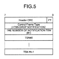
- FIG. 5 is a diagram illustrating an example of the data structure of the TN frame.
- the TN frame has header CRC, FT, control frame type, the number of notification TSNs, and TSN #0 to #n-1.
- Control frame type includes information for notifying of drop of a frame (TSN drop), and "the number of notification TSNs” indicates the number of TSNs whose drop is detected (the number of dropped frames). For example, in the case where "n" dropped frames present, the number of notification TSNs is "n". In TSN#0 to TSN#n-1, the number of TSNs associated with the dropped frames are registered.
- the TN processing unit 160a is means for outputting a TSN. notified in a TN frame which is received from the RNC 200 to the EDCH FP generation processing unit 120.
- the TN processing unit 160b is means for suppressing data communication from the basestation 100a to the RNC 200 by predetermined amount or for a predetermined period when a TC frame (congestion notification) is received from the RNC 200.
- the RNC 200 has an EDCH-FP processing unit 210, a selective synthesizing unit 220, and a control frame generating unit 230.
- the EDCH-FP processing unit 210 is means for controlling data communication with the basestations 100a to 100c and, in the case where an EDCH FP frame is received from the basestations 100a to 100c, outputs the received EDCH FP frame to the selective synthesizing unit 220.
- the EDCH-FP processing unit 210 monitors an FSN included in the EDCH FP frame and, in the case where drop of an FSN is detected, outputs information indicative of the detection of an FNS drop to the control frame generating unit 230.
- the selective synthesizing unit 220 is means, when the EDCH FP frames are obtained, for synthesizing the frames by re-ordering the frames associated with the TSNs on the basis of the TSNs included in the EDCH FP frames.
- the selective synthesizing unit 220 outputs the synthesized frame to the CN.
- the selective synthesizing unit 220 determines whether drop of a TSN presents on the basis of the TSNs associated with the frames and, in the case where drop of a TSN is detected, outputs information of the dropped TSN to the control frame generating unit 230. For example, in the case where the TSNs in the frames are "1", “2", "4", and "5", the selective synthesizing unit 220 determines that the TSN of "3" drops (is missing) and outputs the information of the TSN "3" to the control frame generating unit 230.
- the control frame generating unit 230 is means for generating control frames (TN frame and TC frame) on the basis of detection results of the EDCH-FP processing unit 210 and the selective synthesizing unit 220, and has a TC frame generating unit 230a and a TN frame generating unit 230b.
- the TC frame generating unit 230a is means, in the case where information indicating that drop of an FSN is detected is obtained from the EDCH-FP processing unit 210, for generating a TC frame (congestion notification), and transmitting the generated TC frame to the basestations 100a to 100c.
- the TN frame generating unit 230b is means, in the case where information of the dropped TSN is obtained from the selective synthesizing unit 220, for generating a TN frame (refer to FIG. 5 ) including the information of the dropped TSN and transmitting the generated TN frame to the basestations 100a to 100c.
- the TN frame transmitted from the TN frame generating unit 230b is used, for example, by defining a frame obtained by expanding "control frame type" of "control frame” defined in 3rd Generation Partnership Projection (3GPP).
- the information of the TSN notified by the TN frame is defined so that it can be notified in the list format.
- FIG. 6 is a diagram illustrating an operation example of the mobile communication system according to the first embodiment.
- FIG. 7 is a flowchart illustrating the procedure of the mobile communication system according to the first embodiment.
- the procedure of data communication between the basestation 100a and the RNC 200 will be described.
- the basestation 100a transmits the EDCH FP frame to the RNC 200 (step S1.01), and the RNC 200 receives the EDCH FP frame (step S102) and executes selective synthesizing process (step S103).
- step S105 In the case where no drop of a TSN is detected (No in step S104), an upper-level protocol process is executed (step S105). On the other hand, in the case where drop of a TSN is detected (Yes in step S104), the TSN detected as dropped one is notified to the TN frame generating unit 230b (step S106), and the TN frame is transmitted to the basestation 100a (and the basestations 100b and 100c) (step S107).
- the basestation 100a extracts a TSN from a TN frame (step S108) and determines whether the TSN is buffered. In the case where the FSN is not buffered (No in step S109), the basestation 100a finishes the process.
- the basestation 100a retransmits the EDCH FP frame to the RNC 200 (step S110).
- the RNC 200 receives the EDCH FP frame (step S111) and shifts to step S105.
- the RNC 200 transmits a TN frame to the basestations 100a and 100b, thereby executing retransmission of the EDCH FP frame between the RNC and the basestation to repair the drop. Therefore, an effect that the use efficiency of the wireless band improves is obtained. Simultaneously, retransmission traffic is performed not via a wireless interval having large propagation delay. Consequently, an effect such that the roundtrip time becomes shorter as compared with that in the case of retransmission performed in the RLC layer is obtained.
- the RNC 200 when drop of a frame occurs, the RNC 200 outputs a TN frame to the basestations 100a to 100c, so that probability of obtaining a frame corresponding to the dropped TSN can be improved (it is sufficient that any one of the basestations 100a to 100c holds the frame of the TSN).
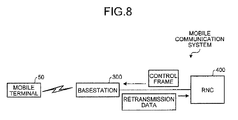
- FIG. 8 is a diagram for explaining the outline and characteristic of the mobile communication system according to the second embodiment.
- the mobile communication system has the mobile terminal 50, a basestation 300, and an RNC 400.
- the interval between the RNC 400 and the basestation 300 is a wired interval, and the interval between the basestation 300 and the mobile terminal 50 is a wireless interval.
- the interface between the mobile terminal and the basestation will be called as Uu, and the interface between the RNC and the basestation will be called Iub/Iur.
- the basestation 300 is an apparatus for relaying data communication executed between the mobile terminal 50 and the RNC 400.
- the basestation 300 in the case where a frame (frame on the MAC-es PDU unit) is received from the mobile terminal 50, the basestation 300 generates an EDCH FP frame obtained by multiplexing frames, and designates Forward Sequence Number (FSN) to the generated EDCH FP frame.
- FSN Forward Sequence Number
- the FSN is a sequence number indicative of the order of the EDCH FP frames.
- the basestation 300 transmits the generated EDCH FP frame to the RNC 400 and buffers the EDCH FP frame by a predetermined amount or for predetermined time.
- the RNC 200 is an apparatus for executing data communication with the mobile terminal 50 via the basestation 300.
- the RNC 400 monitors the FSN included in the EDCH FP frame, and detects drop of the FSN.
- the RNC 200 transmits a control frame including the information of the FSN whose drop is detected to the basestation 300.
- the basestation 300 which receives the control frame determines whether an EDCH FP frame corresponding to the FSN presents in the EDCH FP frames buffered. In the case where the frame presents, an EDCH FP frame including the FSN is retransmitted to the RNC 400.
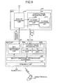
- FIG. 9 is a functional block diagram, illustrating the configuration of the basestation 300 and the RNC 400 according to the second embodiment.
- the basestation 300 has a wireless IF unit 310, an EDCH FP generation processing unit 320, and an Iub IF unit 330. Since the other components are similar to those of a known basestation, their description will not be given.
- the wireless IF unit 310 is means for controlling wireless data communication with the mobile terminal 50.
- the wireless IF unit 310 In the case where a frame (MAG-es PDU) is received from the mobile terminal 50, the wireless IF unit 310 outputs the received frame to the EDCH FP generation processing unit 320.
- the wireless IF unit 310 transmits the obtained frame to the mobile terminal 50.
- the EDCH FP generation processing unit 320 is means for generating an EDCH FP frame obtained by multiplexing frames in the case where a frame is obtained from the wireless IF unit 310. In the case of generating an EDCH FP frame, the EDCH FP generation processing unit 320 gives the FSN (for the data structure of the EDCH FP frame, refer to FIG. 19 ).
- the EDCH FP generation processing unit 320 stores the generated EDCH FP frame in its buffer and outputs the EDCH FP frame to the Iub IF unit 330.
- the EDCH FP generation processing unit 320 stores the EDCH FP frame until predetermined time elapses since the EDCH FP frame is stored.
- the EDCH FP generation processing unit 320 may store the EDCH FP frame up to predetermined capacity and, when there is no remaining capacity in the buffer, sequentially erase the EDCH FP frames from the oldest one.
- the EDCH FP generation processing unit 320 compares the obtained FSN with an FSN included in an EDCH FP frame stored in its buffer to detect the matching FSN, and detects an EDCH FP frame associated with the detected FSN.
- the EDCH FP generation processing unit 320 outputs the detected EDCH FP frame to an RNC transmission processing unit 350 so as to retransmit it to the RNC 400.
- the Iub IF unit 330 is means for controlling data communication with the RNC 400.
- the Iub IF unit 330 has an RNC transmission processing unit 350 and a control frame processing unit 360.
- the RNC transmission processing unit 350 is means for transmitting the obtained EDCH FP frame to the RNC 400 when the EDCH FP frame is obtained from the EDCH FP generation processing unit 320.
- the control frame processing unit 360 is means for executing various processes on the basis of control frames (FN frame and TC frame) transmitted from the RNC 400 and has an FN processing unit 360a and a TC processing unit 360b.
- the TC frame is a control frame transmitted from the RNC 400 when drop of an EDCH FP frame is detected by the RNC 400.
- the FN frame is a control frame transmitted from the RNC 400 in the case where drop of an EDCH FP frame is detected by the RNC 400.
- the FN frame includes an FSN corresponding to a dropped EDCH FP frame.
- FIG. 10 is a diagram illustrating an example of the data structure of the FN frame.
- the FN frame has header CRC, FT, control frame type, the number of notification FSNs, and FSN #0 to #n-1.
- Control frame type includes information for notifying of drop of an EDCH FP frame (FSN drop), and "the number of notification FSNs” indicates the number of FSNs whose drop is detected (the number of dropped EDCH FP frames). For example, in the case where "n" dropped EDCH FP frames present, the number of notification FSNs is "n". In FSN #0 to FSN #n-1, the number of FSNs associated with the dropped EDCH FP frames are registered.
- the FN processing unit 360a is means for outputting an FSN notified in an FN frame which is received from the RNC 400 to the EDCH FP generation processing unit 320.
- the TC processing unit 360b is means for suppressing data communication from the basestation 300 to the RNC 400 by predetermined amount or for a predetermined period when a TC frame (congestion notification) is received from the RNC 400.
- the RNC 400 has an EDCH-FP processing unit 410 and a control frame generating unit 420.
- the EDCH-FP processing unit 410 is means for controlling data communication with the basestation 300 and, in the case where an EDCH FP frame is received from the basestation 300, outputs the received EDCH FP frame to an upper-level processing unit.
- the EDCH-FP processing unit 410 monitors an FSN included in the EDCH FP frame and, in the case where drop of an FSN is detected, outputs information indicative of the detection of an FNS drop and information of the dropped FSN to the control frame generating unit 420.
- the control frame generating unit 420 is means for generating control frames (FN frame and TC frame) on the basis of detection results of the EDCH-FP processing unit 410, and has a TC frame generating unit 420a and an FN frame generating unit 420b.
- the TC frame generating unit 420a is means, in the case where information indicating that drop of an FSN is detected is obtained from the EDCH-FP processing unit 410, for generating a TC frame (congestion notification), and transmitting the generated TC frame to the basestation 300.
- the FN frame generating unit 420b is means, in the case where information of the dropped FSN is obtained from the EDCH-FP processing unit 410, for generating an FN frame (refer to FIG. 10 ) including the information of the dropped FSN and transmitting the generated FN frame to the basestation 300.
- the FN frame transmitted from the FN frame generating unit 420b is used, for example, by defining a frame obtained by expanding control frame type" of "control frame” defined in 3GPP.
- the information of the FSN notified by the TN frame is defined so that it can be notified in the list format.
- FIG. 11 is a diagram, illustrating an operation example of the mobile communication system according to the second embodiment.
- FIG. 12 is a flowchart illustrating the procedure of the mobile communication system according to the second embodiment.
- the basestation 300 transmits the EDCH FP frame to the RNC 400 (step S201), and the RNC 400 receives the EDCH FP frame (step S202).
- the RNC 400 executes an upper-level protocol process (step S204).
- step S203 the FSN detected as dropped one is notified to the FN frame generating unit 420b (step S205), and the FN frame is transmitted to the basestation 300 (step S206).
- the basestation 300 extracts an FSN from an FN frame (step S208) and determines whether the FSN is buffered. In the case where the FSN is not buffered (No in step S209), the basestation 300 finishes the process.
- the basestation 300 retransmits the FP frame to the RNC 400 (step S210).
- the RNC 400 receives the EDCH FP frame (step S207) and shifts to step S204.
- the RNC 400 transmits an FN frame to the basestation 300, thereby executing retransmission of the EDCH FP frame between the RNC and the basestation to repair the drop. Therefore, an effect that the use efficiency of the wireless band improves is obtained. Simultaneously, retransmission traffic is performed not via a wireless interval having large propagation delay. Consequently, an effect such that the roundtrip time becomes shorter as compared with that in the case of retransmission performed in the RLC layer is obtained.
- the corresponding basestation when drop of an FSN occurs, in principle, the corresponding basestation certainly has the dropped EDCH FP frame. Consequently, by performing the retransmission control only on the corresponding basestation, the dropped EDCH FP frame can be obtained, and the burden on the RNC 400 can be also lessened.
- the mobile communication system according to the third embodiment switches a retransmission control method on the basis of the number of basestations connected to the RNC.
- a TN frame is generated, and a frame which is dropped is repaired.
- a TN frame is generated, and a FN frame which is dropped is generated and a frame which is dropped is repaired.
- the mobile communication system switches the frame repairing method on the basis of a connection state between the RNC and the basestation (in the case where an RNC is connected to a plurality of basestations in order to improve probability of repairing a dropped frame between the basestation and the RNC, a TN frame is transmitted to the basestations and, in the case where the RNC is connected to a single basestation, an FN frame is transmitted to the basestation which certainly holds the dropped frame). Therefore, a dropped frame can be repaired with high efficiency.
- FIG. 13 is a functional block diagram illustrating the configuration of the basestations 500a to 500c and the RNC 600 according to the third embodiment. Since the configuration of the basestations 500b and 500c is similar to that of the basestation 500a, the description will not be repeated.
- the basestation 500a has a wireless IF unit 510, an EDCH FP generation processing unit 520, and an Iub IF unit 530. Since the other components are similar to those of a known basestation, their description will not be given.
- the wireless IF unit 510 is means for controlling wireless data communication with the mobile terminal 50.
- the wireless IF unit 510 outputs the received frame to the EDCH FP generation processing unit 520. It is assumed that the TSN is assigned as a sequence number to each of the frames.
- the wireless IF unit 510 transmits the obtained frame to the mobile terminal 50.
- the EDCH FP generation processing unit 520 is means for generating an EDCH FP frame obtained by multiplexing frames in the case where a frame is obtained from the wireless IF unit 510. In the case of generating an EDCH FP frame, the EDCH FP generation processing unit 520 gives the FSN (for the data structure of the EDCH FP frame, refer to FIG. 19 ).
- the EDCH FP generation processing unit 520 stores the generated EDCH FP frame in its buffer and outputs the EDCH FP frame to the Iub IF unit 530.
- the EDCH FP generation processing unit 520 stores the EDCH FP frame until predetermined time elapses since the EDCH FP frame is stored.
- the EDCH FP generation processing unit 520 may store the EDCH FP frame up to predetermined capacity and, when there is no remaining capacity in the buffer, sequentially erase the EDCH FP frames from the oldest one.
- the TSN is obtained from an FN/TN processing unit 560a (explanation of FN/TN processing unit 560a will be described later), the EDCH FP generation processing unit 520 compares the obtained TSN with a TSN included in an EDCH FP frame stored in its buffer to detect the matching TSN, and detects each frame (MAC-es PDU) associated with the detected TSN.
- the EDCH FP generation processing unit 520 generates an EDCH FP frame obtained by multiplexing detected frames and outputs the generated EDCH FP frame to an RNC transmission processing unit 550 so as to retransmit it to the RNC 600.
- the EDCH FP generation processing unit 520 compares the obtained FSN with an FSN included in an EDCH FP frame stored in its buffer to detect the matching FSN, and detects an EDCH FP frame associated with the detected FSN.
- the EDCH FP generation processing unit 520 outputs the detected EDCH FP frame to the RNC transmission processing unit 550 so as to retransmit it to the RNC 600.
- the Iub IF unit 530 is means for controlling data communication with the RNC 600.
- the Iub IF unit 530 has the RNC transmission processing unit 550 and a control frame processing unit 560.
- the RNC transmission processing unit 550 is means for transmitting the obtained EDCH FP frame to the RNC 600 when the EDCH FP frame is obtained from the EDCH FP generation processing unit 520.
- the control frame processing unit 560 is means for executing various processes on the basis of control frames (TN frame, FN frame, and TC frame) transmitted from the RNC 600 and has the FN/TN processing unit 560a and a TC processing unit 560b.
- the TN frame, the FN frame, and TC frame are similar to those described in the first and second embodiments.
- the FN/TN processing unit 560a is means, in the case where an FN frame is received from the RNC 600, for outputting an FSN notified in the FN frame to the EDCH FP generation processing unit 520 and, in the case where a TN frame is received from the RNC 600, outputting a TSN notified by the TN frame to the EDCH FP generation processing unit 520.
- the TC processing unit 560b is means for suppressing data communication from the basestation 500 to the RNC 600 by predetermined amount or for a predetermined period when a TC frame (congestion notification) is received from the RNC 600.
- the RNC 600 has an EDCH-FP processing unit 610, a selective synthesizing unit 620, and a control frame generating unit 630.
- the EDCH-FP processing unit 610 is means for controlling data communication with the basestations 500a to 500c and, in the case where EDCH FP frames are received from the basestations 500a to 500c, outputs the received EDCH FP frame to the selective synthesizing unit 620.
- the EDCH-FP processing unit 610 monitors an FSN included in the EDCH FP frame and, in the case where drop of an FSN is detected, outputs information indicative of the detection of an FNS drop and the FSN directly to the control frame generating unit 630.
- the selective synthesizing unit 620 is means, in the case of obtaining EOCH FP frames, for synthesizing each frame by re-ordering the frames associated with TSNs included in the EDCH FP frames on the basis of the TSNs.
- the selective synthesizing unit 620 outputs the synthesized frame to the CN.
- the selective synthesizing unit 620 determines whether there is drop of a TSNon the basis of the TSNs associated with the frames and, in the case where drop of a TSN is detected, outputs the information of the dropped TSN to the control frame generating unit 630.
- the control frame generating unit 630 is means for generating control frames (TN frame, FN frame, and TC frame) on the basis of detection results of the EDCH-FP processing unit 610 and the selective synthesizing unit 620, and has a TC frame generating unit 630a and an FN/TN frame generating unit 630b.
- the TC frame generating unit 630a is means, in the case where information indicating that drop of an FSN is detected is obtained from the EDCH-FP processing unit 610, for generating a TC frame (congestion notification) and transmitting the generated TC frame to the basestations 500a to 500c.
- the FN/TN frame generating unit 630b is means, in the case where information of the dropped TSN is obtained from the selective synthesizing unit 620, for generating a TN frame (refer to FIG. 5 ) including the information of the dropped TSN and transmitting the generated TN frame to the basestations 500a to 500c.
- the RNC 600 when the RNC 600 is connected to a single basestation (for example, only the basestation 500a), in the case where information of a dropped FSN is obtained from the EDCH-FP processing unit 610, an FN frame (refer to FIG. 10 ) including the information of the dropped TSN is generated, and the generated FN frame is transmitted to the basestation 500a.
- a single basestation for example, only the basestation 500a
- the mobile communication system switches the frame repairing method on the basis of a connection state between the RNC 600 and the basestations 500a to 500c (in the case where the RNC is connected to a plurality of basestations in order to improve probability of repairing a dropped frame between the basestations and the RNC, a TN frame is transmitted to each of the basestations and, in the case where the RNC is connected to a single basestation, an FN frame is transmitted to the basestation which certainly holds the dropped frame). Therefore, a dropped frame can be repaired with high efficiency.
- the components of the basestations 100a to 100c, 300, 500a to 500c and the RNCs 200, 400, and 600 illustrated in FIGS. 4 , 9 , and 13 are function concept and are not always required to be physically constructed as illustrated in the drawings. That is, concrete forms of distribution and integration of the devices are not limited to those illustrated in the diagrams and all or part of them can be functionally or physically distributed/integrated in an arbitrary unit in accordance with various loads, use state, and the like. Further, all or part of the process functions executed in the devices is realized by a CPU and a program analyzed and executed by the CPU or can be realized as hardware by a wired logic.
- FIG. 14 is a diagram (an example) illustrating hardware configuration of a computer 700 serving as a basestation corresponding to the first to third embodiments
- FIG. 15 is a diagram (an example) illustrating hardware configuration of a computer 800 serving as an RNC corresponding to the first to third embodiments.
- the computer (basestation) 700 has an input device 710, an output device 720 such as a display, a buffer 730, a wireless communication apparatus 740 for executing data communication with a mobile terminal, an RNC communication apparatus 750 for executing data communication with an RNC, a Central Processing Unit (CPU) 760, and a Hard Disk Drive (HDD) 770 which are connected via a bus 780.
- an input device 710 an output device 720 such as a display
- a buffer 730 such as a display
- a wireless communication apparatus 740 for executing data communication with a mobile terminal
- RNC communication apparatus 750 for executing data communication with an RNC
- CPU Central Processing Unit
- HDD Hard Disk Drive
- the CPU 760 reads and executes a frame control processing program 770 stored in the HDD 770 to start a frame control processing process 760a.
- the frame control processing process 760a corresponds to the EDCH FP generation processing unit and the control frame processing unit described in the first to third embodiments.
- the CPU stores a frame received from a mobile terminal as frame data 730a in the buffer 730 and, as necessary, transmits the frame data 730a stored in the buffer 730 to the RNC.
- the computer (RNC) 800 has an input device 810, an output device 820 such as a display, a Random Access Memory (RAM) 830, a communication control apparatus 840 for executing data communication with a basestation, a Core Network (CN), and the like, a CPU 850, and an HDD 860 which are connected via a bus 870.
- RNC computer
- a frame drop detecting program 860b displaying a function similar to that of the RNC described in the first to third embodiments is stored.
- the CPU 850 reads and executes the frame drop detecting program 860b to start a frame drop detecting process 850a.
- the frame drop detecting process 850a corresponds to the EDCH-FP processing unit, the selective synthesizing unit, and the control frame generating unit described in the first to third embodiments.
- the HDD 860 stores various data 860a used by the RNC.
- the CPU 850 reads the various data 860a stored in the HDD 860, stores it in the RAM 830, and detects drop of a TSN or FNS by using the various data 830a stored in the RAM 830.
- the frame control processing program 770a illustrated in FIG. 14 and the frame drop detecting program 860b illustrated in FIG. 15 do not always have to be stored in the HDDs 770 and 860 from the beginning.
- the frame control processing program 770a and the frame drop detecting program 860b may be stored in a "portable physical medium” such as a flexible disk (FD), a CD-ROM, a DVD disk, a magnetooptic disk, an IC card which is inserted in a computer, a "fixed physical medium” such as a hard disk drive (HDD) provided on the inside and outside, "another computer (or server)" connected to the computer via a public line, the Internet, LAN, WAN, or the like, or the like.
- the computer may read and execute the frame control processing program 770a and the frame drop detecting program 860b from any of them.
Landscapes
- Engineering & Computer Science (AREA)
- Computer Networks & Wireless Communication (AREA)
- Signal Processing (AREA)
- Mobile Radio Communication Systems (AREA)
Abstract
Description
- The present invention relates to a communication system or the like having a wireless communication apparatus performing wireless communication with a mobile terminal device and a control apparatus for executing data communication with the mobile terminal device via the wireless communication apparatus.
- It is examined to apply the High-Speed Uplink Packet Access (HSUPA) to a mobile communication system of the Wideband-Code Division Multiple Access (W-CDMA) method in order to improve communication speed. The HSUPA is a function of providing an access in an uplink direction of a larger band (direction from a terminal to a network) in a mobile communication system.
- In the following, after explanation of outline of a conventional mobile communication system, a protocol model of the HSUPA will be described.
FIG. 16 is a diagram illustrating the configuration of a conventional mobile communication system. As illustrated in the diagram, the mobile communication system has a mobile terminal (UE) 10, basestations (Node B) 20 to 22, Radio Network Controllers (RNCs) 30 and 31, and a Core Network (CN) 40. - The intervals between the
CN 40, theRNCs basestations basestations 20 to 22 and themobile terminal 10 are wireless intervals. The interface between the mobile terminal and the basestation is called Uu, the interface between the RNC and the basestation is called Iub, the interface between the RNC and the RNC. is called Iur, and the interface between the CN and the RNC is called Iu. - In the mobile communication system of
FIG. 16 , when user data is received by themobile terminal 10, the user data is transmitted to theRNC 30 accommodating themobile terminal 10 via theCN 40. When themobile terminal 10 presents in acell 1, theRNC 30 transmits the user data to thebasestation 20 accommodating thecell 1, and thebasestation 20 transmits the user data to the mobile terminal. On the other hand, the user data transmitted from themobile terminal 10 is received by any of thebasestations 20 to 22, transmitted to theRNCs CN 40. -
FIG. 17 is a diagram for explaining a protocol model of the HSUPA, andFIG. 18 is a diagram illustrating outline of data communication (Iub/Iur boundary). As illustrated inFIG. 17 , a mobile terminal has layers of Application (APL), Radio Link Control (RLC; regarding RLC, refer to 3GPP TS25.322), Medium Access Control (MAC)-d, MAC-es, MAC-e, and physical layer (PHY), and a basestation has layers of MAC-e/Enhanced Dedicated Channel (EDCH) Frame Packet (FP) and PHY/TNL. - The RNC has a D-RNL (relay device) and an S-RNC. The D-RNC has a layer TNL/TNL, and the S-RNC has layers APL, RLC, MAC-d, MAC-es, EDCH FP, and TNL.
- A data frame transmitted in the network direction (uplink direction) by the mobile terminal is divided in, short Packet Data Unit (PDU) by the function of the PLD/MAC-es layer. After that, some MAC-d PDUs are multiplexed, there by constructing an MAC-es PDU (refer to the first to third stages in
FIG. 18 ). - To the MAC-es PDU, a TSN as sequence number is given. In the HSUPA, by simultaneously performing the HARQ in a plurality of channels, the communication rate is improved. However, it is uncertain that data of which channel is received first. Consequently, the order of data received by the basestation is not assured. Due to this, when the mobile terminal transmits data frames, sequence numbers (TSN) are given on the MAC-es unit basis and, to assure order in the RNC, re-ordering is performed according to the TSNs.
- Some more MAC-es PDUs are further multiplexed at the time of transmission from the basestation to an S-RNC and transmitted on the EDCH FP unit basis (EDCH FP frame) onto the Iub. Also to the EDCH FP frame, the FSN as a sequence number is given (refer to the fourth stage in
FIG. 18 ). -
FIG. 19 is a diagram illustrating an example of the data structure of the EDCH FP frame. As illustrated in the diagram, the EDCH FP frame has header and payload, and the header has various control information (not illustrated) and the FSN. The payload has a plurality of Mac-es PDUs, and each MAC-es PDU has a TSN. - On the other hand, on the S-RNC, the MAC-es PDU is extracted from the received EDCH FP frame, re-ordering is performed in accordance with the TSNs and, further, a process of reproducing a data frame is performed by terminating the MAC-d/RLC layer.
- As described above, transmission on the Iub/Iur is performed on the EDCH FP unit basis. Consequently, when a cause of frame drop such as congestion of a line occurs on the Iub/Iur, the unit of the drop also becomes the EDCH FP unit.
- Therefore, in the case where drop occurs on the Iub/Iur, it is repaired by retransmission by the RLC between the mobile terminal and the RNC. In a standard mobile communication system, the S-RNC has the function of detecting the drop by monitoring the FSN of the EDCH FP received, when drop is detected, regarding it as line congestion in the Iub/Iub, and notified the basestation of the congestion indication (TNL congestion indication). The basestation which receives the congestion notification from the RNC side has the function of suppressing data transmission to the Iub/Iur by a predetermined amount or a predetermined period.
-
Patent Document 1 discloses a technique of improving throughput by waiting for an uplink retransmission packet only for predetermined time, transmitting a retransmission wait cancelling request to a wireless network control apparatus and, in the case where a retransmission wait cancellation response of instructing stop of retransmission waiting is received from the wireless network control apparatus, stopping the retransmission waiting. - Patent Document 1: Japanese Laid-open Patent Publication No.
2006-86989 - However, in the case where a frame related to uplink traffic of the mobile communication system drops on the Iub/Iur, data communication has to be executed again between the RNC and the mobile terminal. Consequently, the conventional technique has a problem such that the band of the limited wireless interval is wasted.
- In the case where the HSUPA is newly introduced in the form of expanding an existing W-CDMA system which is already operating, it is not easy to sufficiently assure the band of the Iub/Iur in relation with the existing system. The problems becomes more serious.
- The present invention is achieved to solve the problems of the conventional technique and an object of the invention is to provide a control apparatus, a wireless communication apparatus, a communication system, and a control method capable of improving use efficiency of a wireless band.
- To solve the problems and achieve the object, the control apparatus requires a detecting unit that, when receiving data transmitted from a mobile terminal device via a wireless communication apparatus including a buffer that stores at least one of the data in a predetermined capacity and the data for a predetermined time, detects drop of the data on the basis of sequence numbers included in the data and associated with predetermined data; and a data obtaining unit that, when drop of data is detected by the detecting unit, transmits the sequence numbers corresponding to the dropped data to the wireless communication apparatus and obtains the dropped data from the buffer of the wireless communication apparatus.
- With the control apparatus, in the case where drop of data occurs between the control apparatus and a basestation, by retransmitting data stored in the basestation, drop of the data is repaired. Consequently, an effect of improving use efficiency of the wireless band is obtained. Since the retransmission is performed without using the mobile terminal, the roundtrip can be made short.
-
-
FIG. 1 is a diagram for explaining outline and characteristics of a mobile communication system according to a first embodiment. -
FIG. 2 is a diagram illustrating processes performed at the time of retransmission of a conventional mobile communication system. -
FIG. 3 is a diagram illustrating processes performed at the time of retransmission of a mobile communication system of the present invention. -
FIG. 4 is a functional block diagram illustrating the configuration of a basestation and an RNC in the first embodiment. -
FIG. 5 is a diagram illustrating an example of data structure of a TN frame. -
FIG. 6 is a diagram illustrating an operation example of the mobile communication system according to the first embodiment. -
FIG. 7 is a flowchart illustrating a procedure of the mobile communication system according to the first embodiment. -
FIG. 8 is a diagram for explaining outline and characteristic of a mobile communication system according to a second embodiment. -
FIG. 9 is a functional block diagram illustrating the configuration of a basestation and an RNC in the second embodiment. -
FIG. 10 is a diagram illustrating an example of data structure of an FN frame. -
FIG. 11 is a diagram illustrating an operation example of the mobile communication system according to the second embodiment. -
FIG. 12 is a flowchart illustrating a procedure of the mobile communication system according to the second embodiment. -
FIG. 13 is a functional block diagram illustrating the configuration of a basestation and an RNC in a third embodiment. -
FIG. 14 is a diagram illustrating hardware configuration of a computer serving as a basestation corresponding to the first to third embodiments. -
FIG. 15 is a diagram illustrating hardware configuration of a computer serving as an RNC corresponding to the first to third embodiments. -
FIG. 16 is a diagram illustrating the configuration of a conventional mobile communication system. -
FIG. 17 is a diagram for explaining a protocol model of the HSUPA. -
FIG. 18 is a diagram illustrating outline of data communication (Iub/Iur boundary). -
FIG. 19 is a diagram illustrating an example of the data structure of an EDCH FP frame. -
- 10, 50 Mobile terminal
- 20, 21, 22, 100a, 100b, 300, 500a, 500b, 500c Basestation
- 30, 31, 200, 400, 600 RNC
- 40 CN
- 110, 310, 510 Wireless IF unit
- 120, 320, 520 EDCH FP generation processing unit
- 130, 330, 530 Iub IF unit
- 150, 350, 550 RNC transmission processing unit
- 160, 360, 560 Control frame processing unit
- 160a TN processing unit
- 160b, 360b, 560b TC processing unit
- 210, 410, 610 EDCH-FP processing unit
- 220, 620 Selective synthesizing unit
- 230, 420, 630 Control frame generating unit
- 230a, 420a, 630a TC frame generating unit
- 230b TN frame generating unit
- 360a FN processing unit
- 420b FN frame generating unit
- 560a FN/TN processing unit
- 630b FN/TN frame generating unit
- 700 Computer (basestation)
- 710, 810 Input device
- 720, 820 Output device
- 730 Buffer
- 730a Frame data
- 740 Wireless communication apparatus
- 750 RNC communication apparatus
- 760, 850 CPU
- 760a frame Control processing process
- 770, 860 HDD
- 770a Frame control processing program
- 780, 870 Bus
- 800 Computer (RNC)
- 830 RAM
- 830a, 860a Various data
- 840 Communication control apparatus
- 850a Frame drop detecting process
- 860b Frame drop detecting program
- Preferred embodiments of a control apparatus, a wireless communication apparatus, a communication system, and a control method according to the present invention will be described in detail below with reference to the appended drawings.
- First, the outline and characteristic of a mobile communication system according to a first embodiment will be described.
FIG. 1 is a diagram for explaining the outline and characteristic of the mobile communication system according to the first embodiment. As illustrated in the diagram, the mobile communication system has amobile terminal 50,basestation 100a to 100c, and a Radio Network Controller (RNC) 200. - The intervals between the
RNC 200 and thebasestations 100a to 100c are wired intervals, and the intervals between thebasestations 100a to 100c and themobile terminal 50 are wireless intervals. The interface between the mobile terminal and the basestations will be called as Uu, and the interface between the RNC and the basestations will be called Iub/Iur. - The
mobile terminal 50 is an apparatus for executing transmission/reception of frames (frames include various control data, sound, images, data, and the like) to/from another mobile terminal (not illustrated) by using the mobile communication system. In particular, as a technique related to the present invention, in the case of transmitting a frame (MAC-es PDU) to thebasestations 100a to 100c, themobile terminal 50 assigns Transport Sequence Number (TSN) (refer toFIG. 18 ). The TSN is a sequence number indicative of the order of each frame. It is assumed that the TSN is given in the frame (MAC-es PDU) unit basis by themobile terminal 50. - The
basestation 100a is an apparatus for relaying data communication executed between themobile terminal 50 and theRNC 200. In particular, as a technique related to the present invention, in the case of receiving a frame (MAC-es PDU) from themobile terminal 50, the basestation, 100a generates an EDCH FP frame obtained by multiplexing frames and assigns Forward Sequence Number (FSN) to the generated EDCH FP frame. The FSN is a sequence number indicative of the order of the each FP frame. - The
basestation 100a transmits the generated EDCH FP frame to theRNC 200 and buffers the EDCH FP frame by a predetermined amount or for predetermined time. Since description on thebasestations basestation 100a. - The
RNC 200 is an apparatus for executing data communication with themobile terminal 50 via thebasestations 100a to 100c. In particular, as a technique related to the present invention, in the case of receiving the EDCH FP frame from thebasestations 100a to 100c, theRNC 200 monitors the TSN included in the EDCH FP frame, and detects drop of the TSN. - In the case where drop of the TSN is detected, the
RNC 200 transmits a control frame including the information of the TSN whose drop is detected to thebasestations 100a to 100c. Thebasestations 100a to 100c which receive the control frame determine whether a frame corresponding to the TSN presents in the EDCH FP frames buffered. In the case where the frame presents, an EDCH FP frame including the TSN is retransmitted to theRNC 200. - For example, in
FIG. 1 , in the case where a frame corresponding to the TSN exits in thebasestation 100c, thebasestation 100c retransmits an EDCH FP frame including the TSN to theRNC 200. - An effect of the mobile communication system illustrated in the first embodiment will be described, in comparison with the conventional technique,
FIG. 2 is a diagram illustrating processes at the time of retransmission of the conventional mobile communication system.FIG. 3 is a diagram illustrating processes at the time of retransmission of the mobile communication system of the invention. - As illustrated in
FIG. 2 , even in the case where drop of a frame occurs in the Iub/Iur (between the basestation and the RNC) in the conventional technique, the drop of the frame is solved by the function of an RLC layer. Specifically, since drop is repaired by retransmission between the mobile terminal and the RNC, a problem occurs such that the band in the wireless interval (between the mobile terminal and the basestation) is wasted, and it causes increase in roundtrip time (throughput degradation). - On the other hand, in the mobile communication system according to the first embodiment, as illustrated in
FIG. 3 , in the case where drop of a frame occurs in the Iub/Iur (between the basestation and the RNC), by executing retransmission of the EDCH FP frame between the RNC and the basestation, the drop is repaired. Therefore, an effect that the efficiency of use of the wireless band improves is obtained and, simultaneously, since retransmission traffic is performed not via the wireless interval having large propagation delay, an effect such that the roundtrip time becomes shorter as compared with that in the case of retransmission performed in the RLC layer is obtained. - Next, the configuration of the
basestation 100a and theRNC 200 illustrated inFIG. 1 will be described.Fig. 4 is a functional block diagram illustrating the configuration of thebasestation 100a and theRNC 200 according to the first embodiment. Since the configuration of thebasestations basestation 100a, the description will not be repeated. - First, the configuration of the
basestation 100a will be described. Thebasestation 100a has a wireless IFunit 110, an EDCH FPgeneration processing unit 120, and an Iub IFunit 130. Since the other components are similar to those of a known basestation, their description will not be given. - The wireless IF
unit 110 is means for controlling wireless data communication with themobile terminal 50. In the case where a frame (MAC-es PDU) is received from themobile terminal 50, the wireless IFunit 110 outputs the received frame to the EDCH FPgeneration processing unit 120. It is assumed that the TSN as a sequence number is given to each frame. In the case where a frame addressed to themobile terminal 50 is obtained, the wireless IFunit 110 transmits the obtained frame to themobile terminal 50. - The EDCH FP
generation processing unit 120 is means for generating an EDCH FP frame obtained by multiplexing frames in the case where a frame is obtained by the wireless IFunit 110. In the case of generating an EDCH FP frame, the EDCH FPgeneration processing unit 120 gives the FSN. (for the data structure of the EDCH FP frame, refer toFIG. 19 ). - The EDCH FP
generation processing unit 120 stores the generated EDCH FP frame in its buffer and outputs the EDCH FP frame to the Iub IFunit 130. The EDCH FPgeneration processing unit 120 stores the EDCH FP frame until predetermined time elapses since the EDCH FP frame is stored. Alternately, the EDCH FPgeneration processing unit 120 may store the ETCH FP frame up to predetermined capacity and, when there is no remaining capacity in the buffer, sequentially erase the EDCH FP frames from the oldest one. - When the TSN is obtained from a
TN processing unit 160a (explanation ofTN processing unit 160a will be described later), the EDCH FPgeneration processing unit 120 compares the obtained TSN with a TSN included in an EDCH FP frame stored in its buffer to detect the matching TSN, and detects each frame (MAC-es PDU) associated with the detected TSN. - The EDCH FP
generation processing unit 120 generates an EDCH FP frame obtained by multiplexing the detected frames and outputs the generated EDCH FP frame to a RNCtransmission processing unit 150 so as to retransmit it to theRNC 200. - The Iub IF
unit 130 is means for controlling data communication with theRNC 200. The Iub IFunit 130 has the RNCtransmission processing unit 150 and a controlframe processing unit 160. - The RNC
transmission processing unit 150 is means for transmitting the obtained EDCH FP frame to theRNC 200 when the EDCH FP frame is obtained from the EDCH FPgeneration processing unit 120. - The control
frame processing unit 160 is means for executing various processes on the basis of control frames (TN frame and TC frame) transmitted from theRNC 200 and has theTN control unit 160a and aTC processing unit 160b. - The TC frame is a control frame transmitted from the
RNC 200 when drop of an EDCH FP frame is detected by theRNC 200. On the other hand, the TN frame is a control frame transmitted from theRNC 200 in the case where drop of a frame (MAC-es PDU) is detected by theRNC 200. The TN frame includes a TSN corresponding to a dropped frame. -
FIG. 5 is a diagram illustrating an example of the data structure of the TN frame. As illustrated in the diagram, the TN frame has header CRC, FT, control frame type, the number of notification TSNs, andTSN # 0 to #n-1. "Control frame type" includes information for notifying of drop of a frame (TSN drop), and "the number of notification TSNs" indicates the number of TSNs whose drop is detected (the number of dropped frames). For example, in the case where "n" dropped frames present, the number of notification TSNs is "n". InTSN# 0 to TSN#n-1, the number of TSNs associated with the dropped frames are registered. - The
TN processing unit 160a is means for outputting a TSN. notified in a TN frame which is received from theRNC 200 to the EDCH FPgeneration processing unit 120. TheTN processing unit 160b is means for suppressing data communication from thebasestation 100a to theRNC 200 by predetermined amount or for a predetermined period when a TC frame (congestion notification) is received from theRNC 200. - Subsequently, the configuration of the
RNC 200 will be described. As illustrated inFIG. 4 , theRNC 200 has an EDCH-FP processing unit 210, aselective synthesizing unit 220, and a controlframe generating unit 230. - The EDCH-
FP processing unit 210 is means for controlling data communication with thebasestations 100a to 100c and, in the case where an EDCH FP frame is received from thebasestations 100a to 100c, outputs the received EDCH FP frame to theselective synthesizing unit 220. - The EDCH-
FP processing unit 210 monitors an FSN included in the EDCH FP frame and, in the case where drop of an FSN is detected, outputs information indicative of the detection of an FNS drop to the controlframe generating unit 230. - The
selective synthesizing unit 220 is means, when the EDCH FP frames are obtained, for synthesizing the frames by re-ordering the frames associated with the TSNs on the basis of the TSNs included in the EDCH FP frames. Theselective synthesizing unit 220 outputs the synthesized frame to the CN. - The
selective synthesizing unit 220 determines whether drop of a TSN presents on the basis of the TSNs associated with the frames and, in the case where drop of a TSN is detected, outputs information of the dropped TSN to the controlframe generating unit 230. For example, in the case where the TSNs in the frames are "1", "2", "4", and "5", theselective synthesizing unit 220 determines that the TSN of "3" drops (is missing) and outputs the information of the TSN "3" to the controlframe generating unit 230. - The control
frame generating unit 230 is means for generating control frames (TN frame and TC frame) on the basis of detection results of the EDCH-FP processing unit 210 and theselective synthesizing unit 220, and has a TCframe generating unit 230a and a TNframe generating unit 230b. - The TC
frame generating unit 230a is means, in the case where information indicating that drop of an FSN is detected is obtained from the EDCH-FP processing unit 210, for generating a TC frame (congestion notification), and transmitting the generated TC frame to thebasestations 100a to 100c. - The TN
frame generating unit 230b is means, in the case where information of the dropped TSN is obtained from theselective synthesizing unit 220, for generating a TN frame (refer toFIG. 5 ) including the information of the dropped TSN and transmitting the generated TN frame to thebasestations 100a to 100c. - The TN frame transmitted from the TN
frame generating unit 230b is used, for example, by defining a frame obtained by expanding "control frame type" of "control frame" defined in 3rd Generation Partnership Projection (3GPP). The information of the TSN notified by the TN frame is defined so that it can be notified in the list format. - Next, an operation example of the mobile communication system according to the first embodiment will be described.
FIG. 6 is a diagram illustrating an operation example of the mobile communication system according to the first embodiment. As illustrated inFIG. 6 , themobile terminal 50 transmits frames of TSN = 5 to 14 to thebasestations FIG. 6 ). - The
basestation 100a receives frames of TSN = 5, 6, 8, 9, 11, 13, and 14 (frames of TSN = 7, 10, and 12 drop) (refer to (2-1) inFIG. 6 ) and buffers the frames of TSN = 5, 6, 8, 9, 11, 13, and 14 (refer to (3-1) inFIG. 6 ). - The
basestation 100b receives frames of TSN = 6, 7, 8, 10, 11, 12, and 14 (frames of TSN = 5, 9, and 13 drop) (refer to (2-2) inFIG. 6 ) and buffers the frames of TSN. = 6, 7, 8, 10, 11, 12, and 14 (refer to (3-2) inFIG. 6 ). - The
basestation 100a transmits an EDCH FP frame (FSN=1) obtained by multiplexing frames of TSN = 5, 6, and 8, an EDCH FP frame (FSN = 3) obtained by multiplexing frames of TSN = 9, 11, and 13, and an EDCH FP frame (FSN = 4) including TSN = 14 to theRNC 200. - The
basestation 100b transmits an EDCH FP frame (FSN=2) obtained by multiplexing frames of TSN = 6, 7, and 8, an EDCH FP frame (FSN = 3) obtained by multiplexing frames of TSN = 10, 11, and 12, and an EDCH FP frame (FSN = 4) including TSN = 14 to theRNC 200. It is assumed that drop of the EDCH FP frame of FSN=3 occurs (refer to (4) inFIG. 6 ). - The
RNC 200 receives the EDCH FP frames from thebasestations selective synthesizing unit 220 detects drop of the TSN on the basis of the TSN included in the EDCH FP frames (refer to (5) inFIG. 6 ). In this case, TSN = 10 and 12 out of TSN = 5 to 14 are not included, so that theselective synthesizing unit 220 notifies the TNframe generating unit 230b of the drop of the TSN = 10 and 12. - The TN
frame generating unit 230b generates a TN frame and notifies thebasestations FIG. 6 ). Since the corresponding frames of TSN = 10 and 12 are stored in a storage unit of thebasestation 100b, thebasestation 100b retransmits an EDCH FP frame (FSN = 5) obtained by multiplexing the frames of TSN = 10 and 12 to the RNC 200 (refer to (8) inFIG. 6 ). TheRNC 200 receives the EDCH FP frame (FSN = 5) retransmitted from thebasestation 100b, thereby repairing the frame drop (refer to (9) inFIG. 6 ). - Next, the procedure of the mobile communication system according to the first embodiment will be described.
FIG. 7 is a flowchart illustrating the procedure of the mobile communication system according to the first embodiment. For convenience of explanation, the procedure of data communication between thebasestation 100a and theRNC 200 will be described. - As illustrated in
FIG. 7 , thebasestation 100a transmits the EDCH FP frame to the RNC 200 (step S1.01), and theRNC 200 receives the EDCH FP frame (step S102) and executes selective synthesizing process (step S103). - In the case where no drop of a TSN is detected (No in step S104), an upper-level protocol process is executed (step S105). On the other hand, in the case where drop of a TSN is detected (Yes in step S104), the TSN detected as dropped one is notified to the TN
frame generating unit 230b (step S106), and the TN frame is transmitted to the basestation 100a (and thebasestations - The
basestation 100a extracts a TSN from a TN frame (step S108) and determines whether the TSN is buffered. In the case where the FSN is not buffered (No in step S109), thebasestation 100a finishes the process. - On the other hand, in the case where the TSN is buffered (Yes in step S109), the
basestation 100a retransmits the EDCH FP frame to the RNC 200 (step S110). TheRNC 200 receives the EDCH FP frame (step S111) and shifts to step S105. - As described above, in the mobile communication system according to the first embodiment, in the case where drop of a frame occurs in the Iub/Iur (between the
basestations 100a to 100c and the RNC 200), theRNC 200 transmits a TN frame to thebasestations - In the mobile communication system according to the first embodiment, when drop of a frame occurs, the
RNC 200 outputs a TN frame to thebasestations 100a to 100c, so that probability of obtaining a frame corresponding to the dropped TSN can be improved (it is sufficient that any one of thebasestations 100a to 100c holds the frame of the TSN). - Next, the outline and characteristic of a mobile communication system according to a second embodiment will be described.
FIG. 8 is a diagram for explaining the outline and characteristic of the mobile communication system according to the second embodiment. As illustrated in the diagram, the mobile communication system has themobile terminal 50, abasestation 300, and anRNC 400. - The interval between the
RNC 400 and thebasestation 300 is a wired interval, and the interval between thebasestation 300 and themobile terminal 50 is a wireless interval. The interface between the mobile terminal and the basestation will be called as Uu, and the interface between the RNC and the basestation will be called Iub/Iur. - Since description on the
mobile terminal 50 is similar to that of themobile terminal 50 inFIG. 1 , the same reference numeral is designated and description will not be repeated. - The
basestation 300 is an apparatus for relaying data communication executed between themobile terminal 50 and theRNC 400. In particular, as a technique related to the present invention, in the case where a frame (frame on the MAC-es PDU unit) is received from themobile terminal 50, thebasestation 300 generates an EDCH FP frame obtained by multiplexing frames, and designates Forward Sequence Number (FSN) to the generated EDCH FP frame. - The FSN is a sequence number indicative of the order of the EDCH FP frames. The
basestation 300 transmits the generated EDCH FP frame to theRNC 400 and buffers the EDCH FP frame by a predetermined amount or for predetermined time. - The
RNC 200 is an apparatus for executing data communication with themobile terminal 50 via thebasestation 300. In particular, as a technique related to the present invention, in the case of receiving the EDCH FP frame from thebasestation 300, theRNC 400 monitors the FSN included in the EDCH FP frame, and detects drop of the FSN. - In the case where drop of the FSN is detected, the
RNC 200 transmits a control frame including the information of the FSN whose drop is detected to thebasestation 300. Thebasestation 300 which receives the control frame determines whether an EDCH FP frame corresponding to the FSN presents in the EDCH FP frames buffered. In the case where the frame presents, an EDCH FP frame including the FSN is retransmitted to theRNC 400. - As described above, in the mobile communication system according to the second embodiment, in the case where drop of an EDCH FP frame occurs in Iub/Iur (between the basestation and the RNC), by executing retransmission of the EDCH FP frame between the RNC and the basestation, the drop is repaired. Therefore, an effect that the efficiency of use of the wireless band improves is obtained and, simultaneously, since retransmission traffic is performed not via the wireless interval having large propagation delay, an effect such that the roundtrip time becomes shorter as compared with that in the case of retransmission performed in the RLC layer is obtained.
- Next, the configuration of the
basestation 300 and theRNC 400 illustrated inFIG. 8 will be described.FIG. 9 is a functional block diagram, illustrating the configuration of thebasestation 300 and theRNC 400 according to the second embodiment. - First, the configuration of the
basestation 300 will be described. Thebasestation 300 has a wireless IFunit 310, an EDCH FPgeneration processing unit 320, and an Iub IFunit 330. Since the other components are similar to those of a known basestation, their description will not be given. - The wireless IF
unit 310 is means for controlling wireless data communication with themobile terminal 50. In the case where a frame (MAG-es PDU) is received from themobile terminal 50, the wireless IFunit 310 outputs the received frame to the EDCH FPgeneration processing unit 320. In the case where a frame addressed to themobile terminal 50 is obtained, the wireless IFunit 310 transmits the obtained frame to themobile terminal 50. - The EDCH FP
generation processing unit 320 is means for generating an EDCH FP frame obtained by multiplexing frames in the case where a frame is obtained from the wireless IFunit 310. In the case of generating an EDCH FP frame, the EDCH FPgeneration processing unit 320 gives the FSN (for the data structure of the EDCH FP frame, refer toFIG. 19 ). - The EDCH FP
generation processing unit 320 stores the generated EDCH FP frame in its buffer and outputs the EDCH FP frame to the Iub IFunit 330. The EDCH FPgeneration processing unit 320 stores the EDCH FP frame until predetermined time elapses since the EDCH FP frame is stored. Alternately, the EDCH FPgeneration processing unit 320 may store the EDCH FP frame up to predetermined capacity and, when there is no remaining capacity in the buffer, sequentially erase the EDCH FP frames from the oldest one. - When the FSN is obtained from an
FN processing unit 360a (explanation ofFN processing unit 360a will be described later), the EDCH FPgeneration processing unit 320 compares the obtained FSN with an FSN included in an EDCH FP frame stored in its buffer to detect the matching FSN, and detects an EDCH FP frame associated with the detected FSN. The EDCH FPgeneration processing unit 320 outputs the detected EDCH FP frame to an RNC transmission processing unit 350 so as to retransmit it to theRNC 400. - The Iub IF
unit 330 is means for controlling data communication with theRNC 400. The Iub IFunit 330 has an RNC transmission processing unit 350 and a controlframe processing unit 360. - The RNC transmission processing unit 350 is means for transmitting the obtained EDCH FP frame to the
RNC 400 when the EDCH FP frame is obtained from the EDCH FPgeneration processing unit 320. - The control
frame processing unit 360 is means for executing various processes on the basis of control frames (FN frame and TC frame) transmitted from theRNC 400 and has anFN processing unit 360a and aTC processing unit 360b. - The TC frame is a control frame transmitted from the
RNC 400 when drop of an EDCH FP frame is detected by theRNC 400. On the other hand, the FN frame is a control frame transmitted from theRNC 400 in the case where drop of an EDCH FP frame is detected by theRNC 400. The FN frame includes an FSN corresponding to a dropped EDCH FP frame. -
FIG. 10 is a diagram illustrating an example of the data structure of the FN frame. As illustrated in the diagram, the FN frame has header CRC, FT, control frame type, the number of notification FSNs, andFSN # 0 to #n-1. "Control frame type" includes information for notifying of drop of an EDCH FP frame (FSN drop), and "the number of notification FSNs" indicates the number of FSNs whose drop is detected (the number of dropped EDCH FP frames). For example, in the case where "n" dropped EDCH FP frames present, the number of notification FSNs is "n". InFSN # 0 to FSN #n-1, the number of FSNs associated with the dropped EDCH FP frames are registered. - The
FN processing unit 360a is means for outputting an FSN notified in an FN frame which is received from theRNC 400 to the EDCH FPgeneration processing unit 320. TheTC processing unit 360b is means for suppressing data communication from thebasestation 300 to theRNC 400 by predetermined amount or for a predetermined period when a TC frame (congestion notification) is received from theRNC 400. - Subsequently, the configuration of the
RNC 400 will be described. As illustrated inFIG. 9 , theRNC 400 has an EDCH-FP processing unit 410 and a controlframe generating unit 420. The EDCH-FP processing unit 410 is means for controlling data communication with thebasestation 300 and, in the case where an EDCH FP frame is received from thebasestation 300, outputs the received EDCH FP frame to an upper-level processing unit. - The EDCH-
FP processing unit 410 monitors an FSN included in the EDCH FP frame and, in the case where drop of an FSN is detected, outputs information indicative of the detection of an FNS drop and information of the dropped FSN to the controlframe generating unit 420. - The control
frame generating unit 420 is means for generating control frames (FN frame and TC frame) on the basis of detection results of the EDCH-FP processing unit 410, and has a TCframe generating unit 420a and an FNframe generating unit 420b. - The TC
frame generating unit 420a is means, in the case where information indicating that drop of an FSN is detected is obtained from the EDCH-FP processing unit 410, for generating a TC frame (congestion notification), and transmitting the generated TC frame to thebasestation 300. - The FN
frame generating unit 420b is means, in the case where information of the dropped FSN is obtained from the EDCH-FP processing unit 410, for generating an FN frame (refer toFIG. 10 ) including the information of the dropped FSN and transmitting the generated FN frame to thebasestation 300. - The FN frame transmitted from the FN
frame generating unit 420b is used, for example, by defining a frame obtained by expanding control frame type" of "control frame" defined in 3GPP. The information of the FSN notified by the TN frame is defined so that it can be notified in the list format. - Next, an operation example of the mobile communication system according to the second embodiment will be described.
FIG. 11 is a diagram, illustrating an operation example of the mobile communication system according to the second embodiment. As illustrated inFIG. 11 , themobile terminal 50 transmits frames of TSN = 5 to 14 to the basestation 300 (refer to (1) inFIG. 11 ) . - The
basestation 300 receives frames of TSN. 5 to 14, generates an EDCH FP frame (FSN = 1) obtained by multiplexing TSN = 5 to 7, an EDCH FP frame (FSN = 2) obtained by multiplexing TSN = 8 to 10, an EDCH FP frame (FSN = 3) obtained by multiplexing TSN = 11 and 12, and an EDCH FP frame (FSN = 4) obtained by multiplexing TSN = 13 and 14, and buffers the generated EDCH FP frames (refer to (2) inFIG, 11 ). - The
basestation 300 transmits the EDCH FP frames (FSN = 1 to 4) to theRNC 400. It is assumed that drop of the EDCH FP frame of FSN = 2 occurs at this time (refer to (3) inFIG. 11 ). - The
RNC 400 receives the EDCH FP frames from thebasestation 300, and the EDCH-FP processing unit 410 detects drop of the FSN on the basis of FSNs included in the EDCH FP frames (refer to (4) inFIG. 11 ). In this case, FSN = 2 (TSN = 8, 9, and 10) is not included, so that the EDCH-FP processing unit 410 notifies the FNframe generating unit 420b of the drop of FSN = 2. - The FN
frame generating unit 420b generates an FN frame and notifies thebasestation 300 of FSN = 2 (refer to (5) and (6) inFIG. 11 ) . Since the corresponding EDCH FP frame of FSN = 2 is stored in a storage unit of thebasestation 300, thebasestation 300 retransmits an EDCH FP frame of FSN = 2 (refer to (7) inFIG. 11 ). TheRNC 400 receives the EDCH FP frame (FSN = 2) retransmitted from thebasestation 300, thereby repairing the frame drop (refer to (8) inFIG. 11 ). - Next, the procedure of the mobile communication system according to the second embodiment will be described.
FIG. 12 is a flowchart illustrating the procedure of the mobile communication system according to the second embodiment. As illustrated in the diagram, thebasestation 300 transmits the EDCH FP frame to the RNC 400 (step S201), and theRNC 400 receives the EDCH FP frame (step S202). In the case where no drop of an FSN is detected (No in step S203), theRNC 400 executes an upper-level protocol process (step S204). - On the other hand, in the case where drop of an FSN is detected (Yes in step S203), the FSN detected as dropped one is notified to the FN
frame generating unit 420b (step S205), and the FN frame is transmitted to the basestation 300 (step S206). - The
basestation 300 extracts an FSN from an FN frame (step S208) and determines whether the FSN is buffered. In the case where the FSN is not buffered (No in step S209), thebasestation 300 finishes the process. - On the other hand, in the case where the FSN is buffered (Yes in step S209), the
basestation 300 retransmits the FP frame to the RNC 400 (step S210). TheRNC 400 receives the EDCH FP frame (step S207) and shifts to step S204. - As described above, in the mobile communication system according to the second embodiments, in the case where drop of an EDCH FP frame occurs in the Iub/Iur (between the
basestation 300 and the RNC 400), theRNC 400 transmits an FN frame to thebasestation 300, thereby executing retransmission of the EDCH FP frame between the RNC and the basestation to repair the drop. Therefore, an effect that the use efficiency of the wireless band improves is obtained. Simultaneously, retransmission traffic is performed not via a wireless interval having large propagation delay. Consequently, an effect such that the roundtrip time becomes shorter as compared with that in the case of retransmission performed in the RLC layer is obtained. - In the mobile communication system according to the second embodiment, when drop of an FSN occurs, in principle, the corresponding basestation certainly has the dropped EDCH FP frame. Consequently, by performing the retransmission control only on the corresponding basestation, the dropped EDCH FP frame can be obtained, and the burden on the
RNC 400 can be also lessened. - Next, the outline and characteristic of a mobile communication system, according to a third embodiment will be described. The mobile communication system according to the third embodiment switches a retransmission control method on the basis of the number of basestations connected to the RNC.
- Concretely, in the case where drop of a TSN is detected in a state where a plurality of basestations are connected to an RNC, by using the method of the foregoing first embodiment, a TN frame is generated, and a frame which is dropped is repaired. On the other hand, in the case where drop of an FSN is detected in a state where a single basestation is connected to an RNC, by using the method of the foregoing second embodiment, a TN frame is generated, and a FN frame which is dropped is generated and a frame which is dropped is repaired.
- As described above, the mobile communication system according to the third embodiment switches the frame repairing method on the basis of a connection state between the RNC and the basestation (in the case where an RNC is connected to a plurality of basestations in order to improve probability of repairing a dropped frame between the basestation and the RNC, a TN frame is transmitted to the basestations and, in the case where the RNC is connected to a single basestation, an FN frame is transmitted to the basestation which certainly holds the dropped frame). Therefore, a dropped frame can be repaired with high efficiency.
- Next, the configuration of
basestations 500a to 500c and anRNC 600 according to the third embodiment will be described.FIG. 13 is a functional block diagram illustrating the configuration of thebasestations 500a to 500c and theRNC 600 according to the third embodiment. Since the configuration of thebasestations 500b and 500c is similar to that of thebasestation 500a, the description will not be repeated. - First, the configuration of the
basestation 500a will be described. Thebasestation 500a has a wireless IFunit 510, an EDCH FPgeneration processing unit 520, and an Iub IFunit 530. Since the other components are similar to those of a known basestation, their description will not be given. - The wireless IF
unit 510 is means for controlling wireless data communication with themobile terminal 50. In the case where a frame (MAC-es PDU) is received from themobile terminal 50, the wireless IFunit 510 outputs the received frame to the EDCH FPgeneration processing unit 520. It is assumed that the TSN is assigned as a sequence number to each of the frames. In the case where a frame addressed to themobile terminal 50 is obtained, the wireless IFunit 510 transmits the obtained frame to themobile terminal 50. - The EDCH FP
generation processing unit 520 is means for generating an EDCH FP frame obtained by multiplexing frames in the case where a frame is obtained from the wireless IFunit 510. In the case of generating an EDCH FP frame, the EDCH FPgeneration processing unit 520 gives the FSN (for the data structure of the EDCH FP frame, refer toFIG. 19 ). - The EDCH FP
generation processing unit 520 stores the generated EDCH FP frame in its buffer and outputs the EDCH FP frame to the Iub IFunit 530. The EDCH FPgeneration processing unit 520 stores the EDCH FP frame until predetermined time elapses since the EDCH FP frame is stored. Alternately, the EDCH FPgeneration processing unit 520 may store the EDCH FP frame up to predetermined capacity and, when there is no remaining capacity in the buffer, sequentially erase the EDCH FP frames from the oldest one. - Wen the TSN is obtained from an FN/
TN processing unit 560a (explanation of FN/TN processing unit 560a will be described later), the EDCH FPgeneration processing unit 520 compares the obtained TSN with a TSN included in an EDCH FP frame stored in its buffer to detect the matching TSN, and detects each frame (MAC-es PDU) associated with the detected TSN. - The EDCH FP
generation processing unit 520 generates an EDCH FP frame obtained by multiplexing detected frames and outputs the generated EDCH FP frame to an RNCtransmission processing unit 550 so as to retransmit it to theRNC 600. - On the other hand, when the FSN is obtained from the FN/
TN processing unit 560a, the EDCH FPgeneration processing unit 520 compares the obtained FSN with an FSN included in an EDCH FP frame stored in its buffer to detect the matching FSN, and detects an EDCH FP frame associated with the detected FSN. The EDCH FPgeneration processing unit 520 outputs the detected EDCH FP frame to the RNCtransmission processing unit 550 so as to retransmit it to theRNC 600. - The Iub IF
unit 530 is means for controlling data communication with theRNC 600. The Iub IFunit 530 has the RNCtransmission processing unit 550 and a controlframe processing unit 560. - The RNC
transmission processing unit 550 is means for transmitting the obtained EDCH FP frame to theRNC 600 when the EDCH FP frame is obtained from the EDCH FPgeneration processing unit 520. - The control
frame processing unit 560 is means for executing various processes on the basis of control frames (TN frame, FN frame, and TC frame) transmitted from theRNC 600 and has the FN/TN processing unit 560a and aTC processing unit 560b. - The TN frame, the FN frame, and TC frame are similar to those described in the first and second embodiments.
- The FN/
TN processing unit 560a is means, in the case where an FN frame is received from theRNC 600, for outputting an FSN notified in the FN frame to the EDCH FPgeneration processing unit 520 and, in the case where a TN frame is received from theRNC 600, outputting a TSN notified by the TN frame to the EDCH FPgeneration processing unit 520. - The
TC processing unit 560b is means for suppressing data communication from the basestation 500 to theRNC 600 by predetermined amount or for a predetermined period when a TC frame (congestion notification) is received from theRNC 600. - Subsequently, the configuration of the
RNC 600 will be described. As illustrated inFIG. 13 , theRNC 600 has an EDCH-FP processing unit 610, aselective synthesizing unit 620, and a controlframe generating unit 630. - The EDCH-
FP processing unit 610 is means for controlling data communication with thebasestations 500a to 500c and, in the case where EDCH FP frames are received from thebasestations 500a to 500c, outputs the received EDCH FP frame to theselective synthesizing unit 620. - The EDCH-
FP processing unit 610 monitors an FSN included in the EDCH FP frame and, in the case where drop of an FSN is detected, outputs information indicative of the detection of an FNS drop and the FSN directly to the controlframe generating unit 630. - The
selective synthesizing unit 620 is means, in the case of obtaining EOCH FP frames, for synthesizing each frame by re-ordering the frames associated with TSNs included in the EDCH FP frames on the basis of the TSNs. Theselective synthesizing unit 620 outputs the synthesized frame to the CN. - When connected to a plurality of basestations, the
selective synthesizing unit 620 determines whether there is drop of a TSNon the basis of the TSNs associated with the frames and, in the case where drop of a TSN is detected, outputs the information of the dropped TSN to the controlframe generating unit 630. - The control
frame generating unit 630 is means for generating control frames (TN frame, FN frame, and TC frame) on the basis of detection results of the EDCH-FP processing unit 610 and theselective synthesizing unit 620, and has a TCframe generating unit 630a and an FN/TNframe generating unit 630b. - The TC
frame generating unit 630a is means, in the case where information indicating that drop of an FSN is detected is obtained from the EDCH-FP processing unit 610, for generating a TC frame (congestion notification) and transmitting the generated TC frame to thebasestations 500a to 500c. - The FN/TN
frame generating unit 630b is means, in the case where information of the dropped TSN is obtained from theselective synthesizing unit 620, for generating a TN frame (refer toFIG. 5 ) including the information of the dropped TSN and transmitting the generated TN frame to thebasestations 500a to 500c. - On the other hand, when the
RNC 600 is connected to a single basestation (for example, only thebasestation 500a), in the case where information of a dropped FSN is obtained from the EDCH-FP processing unit 610, an FN frame (refer toFIG. 10 ) including the information of the dropped TSN is generated, and the generated FN frame is transmitted to thebasestation 500a. - As described above, the mobile communication system according to the third embodiment switches the frame repairing method on the basis of a connection state between the
RNC 600 and thebasestations 500a to 500c (in the case where the RNC is connected to a plurality of basestations in order to improve probability of repairing a dropped frame between the basestations and the RNC, a TN frame is transmitted to each of the basestations and, in the case where the RNC is connected to a single basestation, an FN frame is transmitted to the basestation which certainly holds the dropped frame). Therefore, a dropped frame can be repaired with high efficiency. - All or part of the processes described as processes automatically performed in the processes described in the first to third embodiments can be performed manually, or all or part of the processes described as processes performed manually can be automatically performed by a known method. Information including the process procedures, control procedures, concrete names, various data, and parameters described and illustrated in the foregoing document and the drawings can be arbitrarily changed unless otherwise specified.
- The components of the
basestations 100a to 100c, 300, 500a to 500c and theRNCs FIGS. 4 ,9 , and13 are function concept and are not always required to be physically constructed as illustrated in the drawings. That is, concrete forms of distribution and integration of the devices are not limited to those illustrated in the diagrams and all or part of them can be functionally or physically distributed/integrated in an arbitrary unit in accordance with various loads, use state, and the like. Further, all or part of the process functions executed in the devices is realized by a CPU and a program analyzed and executed by the CPU or can be realized as hardware by a wired logic. -
FIG. 14 is a diagram (an example) illustrating hardware configuration of acomputer 700 serving as a basestation corresponding to the first to third embodiments, andFIG. 15 is a diagram (an example) illustrating hardware configuration of acomputer 800 serving as an RNC corresponding to the first to third embodiments. - As illustrated in
FIG. 14 , the computer (basestation) 700 has aninput device 710, an output device 720 such as a display, abuffer 730, awireless communication apparatus 740 for executing data communication with a mobile terminal, anRNC communication apparatus 750 for executing data communication with an RNC, a Central Processing Unit (CPU) 760, and a Hard Disk Drive (HDD) 770 which are connected via abus 780. - The
CPU 760 reads and executes a framecontrol processing program 770 stored in theHDD 770 to start a framecontrol processing process 760a. The framecontrol processing process 760a corresponds to the EDCH FP generation processing unit and the control frame processing unit described in the first to third embodiments. The CPU stores a frame received from a mobile terminal asframe data 730a in thebuffer 730 and, as necessary, transmits theframe data 730a stored in thebuffer 730 to the RNC. - As illustrated in
FIG. 15 , the computer (RNC) 800 has an input device 810, anoutput device 820 such as a display, a Random Access Memory (RAM) 830, a communication control apparatus 840 for executing data communication with a basestation, a Core Network (CN), and the like, aCPU 850, and anHDD 860 which are connected via abus 870. - In the
HDD 860, a framedrop detecting program 860b displaying a function similar to that of the RNC described in the first to third embodiments is stored. TheCPU 850 reads and executes the framedrop detecting program 860b to start a framedrop detecting process 850a. The framedrop detecting process 850a corresponds to the EDCH-FP processing unit, the selective synthesizing unit, and the control frame generating unit described in the first to third embodiments. - The
HDD 860 storesvarious data 860a used by the RNC. TheCPU 850 reads thevarious data 860a stored in theHDD 860, stores it in theRAM 830, and detects drop of a TSN or FNS by using thevarious data 830a stored in theRAM 830. - The frame
control processing program 770a illustrated inFIG. 14 and the framedrop detecting program 860b illustrated inFIG. 15 do not always have to be stored in theHDDs control processing program 770a and the framedrop detecting program 860b may be stored in a "portable physical medium" such as a flexible disk (FD), a CD-ROM, a DVD disk, a magnetooptic disk, an IC card which is inserted in a computer, a "fixed physical medium" such as a hard disk drive (HDD) provided on the inside and outside, "another computer (or server)" connected to the computer via a public line, the Internet, LAN, WAN, or the like, or the like. The computer may read and execute the framecontrol processing program 770a and the framedrop detecting program 860b from any of them.
Claims (18)
- A control apparatus comprising:a detecting unit that, when receiving data transmitted from a mobile terminal device via a wireless communication apparatus including a buffer that stores at least one of the data in a predetermined capacity and the data for a predetermined time, detects drop of the data on the basis of sequence numbers included in the data and associated with predetermined data; anda data obtaining unit that, when drop of data is detected by the detecting unit, transmits the sequence number corresponding to the dropped data to the wireless communication apparatus and obtains the dropped data from the buffer of the wireless communication apparatus.
- The control apparatus according to claim 1, wherein the sequence number is a sequence number that is set for each packet transmitted from the mobile terminal device.
- The control apparatus according to claim 1 or 2, wherein if a plurality of wireless communication apparatuses are connected to the control apparatus, the data obtaining unit transmits the sequence number to each of the wireless communication apparatuses and obtains dropped data from any one of the wireless communication apparatuses to which the sequence number is transmitted.
- The control apparatus according to claim 1, wherein the sequence number is a sequence number that is set for each frame obtained by multiplexing packets transmitted from the mobile terminal device.
- A wireless communication apparatus comprising:a storing unit that stores data transmitted from a mobile terminal device up to at least one of a predetermined capacity and a predetermined time; anda transmitting unit that, when receiving a sequence number corresponding to dropped data from a control apparatus which transmits the data, detects data corresponding to the sequence number from the storing unit, and transmits the detected data to the control apparatus .
- A communication system comprising:a wireless communication apparatus that performs wireless communication with a mobile terminal device; anda control apparatus that executes data communication with the mobile terminal device via the wireless communication apparatus,wherein the wireless communication apparatus includes a storing unit that stores data transmitted from the mobile terminal device up to at least one of a predetermined capacity and a predetermined time, andthe control apparatus includes
a detecting unit that, when receiving data from the mobile terminal device via the wireless communication apparatus, detects drop of data on the basis of sequence numbers included in the data; and
a data obtaining unit that, when drop of data is detected by the detecting unit, transmits the sequence number corresponding to the dropped data to the wireless communication apparatus and obtains the dropped data from the storing unit of the wireless communication apparatus. - The communication system according to claim 6, wherein the sequence number is a sequence number that is set for each packet transmitted from the mobile terminal device.
- The communication system according to claim 6 or 7, wherein if a plurality of wireless communication apparatuses are connected to the control apparatus, the data obtaining unit transmits the sequence number to each of the wireless communication apparatuses and obtains the dropped data from any one of the wireless communication apparatuses to which the sequence number is transmitted.
- The communication system according to claim 6, wherein the sequence number is a sequence number that is set for each frame obtained by multiplexing packets transmitted from the mobile terminal device.
- A control method for a communication system that includes a wireless communication apparatus performing wireless communication with a mobile terminal device and a control apparatus executing data communication with the mobile terminal device via the wireless communication apparatus, the control method comprisinga step of storing data in a buffer transmitted from the mobile terminal device up to at least one of a predetermined capacity and a predetermined time by the wireless communication apparatus; anda step of detecting, when data is received from the mobile terminal device via the wireless communication apparatus, drop of data on the basis of sequence numbers included in the data; anda step of transmitting, when drop of data is detected, the sequence number corresponding to the dropped data to the wireless communication apparatus, and obtaining the dropped data from the buffer of the wireless communication apparatus.
- The control method according to claim 10, wherein the sequence number is a sequence number that is set for each packet transmitted from the mobile terminal device.
- The control method according to claim 10 or 11, wherein if a plurality of wireless communication apparatuses are connected to the control apparatus, the sequence number is transmitted to each of the wireless communication apparatuses and the dropped data is obtained from any one of the wireless communication apparatuses to which the sequence number is transmitted.
- The control method according to claim 10, wherein the sequence number is a sequence number that is set for each frame obtained by multiplexing packets transmitted from the mobile terminal device.
- A control program for causing a computer to execute:a detecting step of detecting, when data is received from a wireless communication apparatus including a buffer that stores at least one of data transmitted from a mobile terminal device in a predetermined capacity and data transmitted from the mobile terminal device for a predetermined time, drop of data on the basis of a sequence number associated with predetermined data; anda data obtaining step of transmitting, when drop of data is detected by the detecting procedure, the sequence number corresponding to the dropped data to the wireless communication apparatus, and obtaining the dropped data from the buffer of the wireless communication apparatus.
- The control program according to claim 14, wherein the sequence number is a sequence number that is set for each packet transmitted from the mobile terminal device.
- The control program according to claim 14 or 15, wherein the data obtaining step includes transmitting, if a plurality of wireless communication apparatuses are connected, the sequence number to each of the wireless communication apparatuses, and obtaining the dropped data from any one of the transmitted wireless communication apparatuses.
- The control program according to claim 14, wherein the sequence number is a sequence number that is set for each frame obtained by multiplexing packets transmitted from the mobile terminal device.
- A control program for causing a computer to execute:a storing step of storing data transmitted from a mobile terminal device to a storing device up to at least one of a predetermined capacity and a predetermined time; anda transmitting step of detecting, when a sequence number corresponding to dropped data is received from a control apparatus which transmitted the data, data corresponding to the sequence number from the storing apparatus, and transmitting the detected data to the control apparatus.
Applications Claiming Priority (1)
| Application Number | Priority Date | Filing Date | Title |
|---|---|---|---|
| PCT/JP2008/058428 WO2009133626A1 (en) | 2008-05-02 | 2008-05-02 | Controller, wireless communication device, communication system and controlling method |
Publications (2)
| Publication Number | Publication Date |
|---|---|
| EP2276316A1 true EP2276316A1 (en) | 2011-01-19 |
| EP2276316A4 EP2276316A4 (en) | 2013-12-18 |
Family
ID=41254855
Family Applications (1)
| Application Number | Title | Priority Date | Filing Date |
|---|---|---|---|
| EP08752333.8A Withdrawn EP2276316A4 (en) | 2008-05-02 | 2008-05-02 | CONTROLLER, COMMUNICATION DEVICE, COMMUNICATION SYSTEM, AND CONTROL METHOD |
Country Status (4)
| Country | Link |
|---|---|
| US (1) | US8670382B2 (en) |
| EP (1) | EP2276316A4 (en) |
| JP (1) | JP5093344B2 (en) |
| WO (1) | WO2009133626A1 (en) |
Cited By (2)
| Publication number | Priority date | Publication date | Assignee | Title |
|---|---|---|---|---|
| WO2013070162A1 (en) * | 2011-11-10 | 2013-05-16 | Telefonaktiebolaget L M Ericsson (Publ) | Methods, radio base station and radio network controller |
| CN109688631A (en) * | 2017-10-19 | 2019-04-26 | 中国移动通信有限公司研究院 | A kind of connection processing method and equipment |
Families Citing this family (5)
| Publication number | Priority date | Publication date | Assignee | Title |
|---|---|---|---|---|
| JP4965682B2 (en) * | 2010-04-05 | 2012-07-04 | 株式会社エヌ・ティ・ティ・ドコモ | Radio communication system, radio control apparatus, radio base station, and radio communication method |
| CN103348756B (en) * | 2011-02-10 | 2016-10-26 | 富士通株式会社 | Wireless communication system, reception device, dispensing device and wireless communications method |
| WO2012115545A1 (en) * | 2011-02-22 | 2012-08-30 | Telefonaktiebolaget L M Ericsson (Publ) | Method and device for congestion situations |
| FR3014274A1 (en) * | 2013-12-03 | 2015-06-05 | Commissariat Energie Atomique | METHOD AND DEVICE FOR RETRANSMITTING DATA IN MOBILE NETWORKS |
| CN106256101B (en) * | 2014-05-08 | 2019-10-25 | 华为技术有限公司 | Network device for joint decoding and method thereof |
Family Cites Families (10)
| Publication number | Priority date | Publication date | Assignee | Title |
|---|---|---|---|---|
| EP1096719A3 (en) * | 1999-11-01 | 2007-12-05 | Matsushita Electric Industrial Co., Ltd. | Relay data retransmission method and system |
| WO2001099355A1 (en) * | 2000-06-23 | 2001-12-27 | Mitsubishi Denki Kabushiki Kaisha | Method and system for packet retransmission |
| US6636488B1 (en) * | 2000-10-11 | 2003-10-21 | Aperto Networks, Inc. | Automatic retransmission and error recovery for packet oriented point-to-multipoint communication |
| EP1523835B1 (en) * | 2002-06-21 | 2006-02-01 | Siemens Aktiengesellschaft | Method and communication station for transmitting data |
| WO2005104672A2 (en) | 2004-05-05 | 2005-11-10 | Telefonaktiebolaget Lm Ericsson (Publ) | Hsdpa flow control data frame, frame sequence number |
| JP2006086989A (en) | 2004-09-17 | 2006-03-30 | Matsushita Electric Ind Co Ltd | Mobile communication system, radio base station apparatus, radio network control apparatus, mobile communication method, and mobile communication program |
| KR100976732B1 (en) * | 2005-12-01 | 2010-08-18 | 삼성전자주식회사 | Retransmission Apparatus and Method Using Relay Station in Multi-hop Network |
| JP2007300502A (en) * | 2006-05-01 | 2007-11-15 | Ntt Docomo Inc | System, method, base station and mobile station for data transmission |
| JP5140975B2 (en) | 2006-09-14 | 2013-02-13 | 富士通株式会社 | Mobile communication system and communication method thereof |
| ATE510387T1 (en) * | 2007-11-01 | 2011-06-15 | Ericsson Telefon Ab L M | EFFICIENT FLOW CONTROL IN A RADIO NETWORK CONTROL DEVICE (RNC) |
-
2008
- 2008-05-02 WO PCT/JP2008/058428 patent/WO2009133626A1/en not_active Ceased
- 2008-05-02 EP EP08752333.8A patent/EP2276316A4/en not_active Withdrawn
- 2008-05-02 JP JP2010509985A patent/JP5093344B2/en not_active Expired - Fee Related
-
2010
- 2010-10-28 US US12/914,586 patent/US8670382B2/en not_active Expired - Fee Related
Cited By (5)
| Publication number | Priority date | Publication date | Assignee | Title |
|---|---|---|---|---|
| WO2013070162A1 (en) * | 2011-11-10 | 2013-05-16 | Telefonaktiebolaget L M Ericsson (Publ) | Methods, radio base station and radio network controller |
| US9325594B2 (en) | 2011-11-10 | 2016-04-26 | Telefonaktiebolaget Lm Ericsson (Publ) | Methods, radio base station and radio network controller |
| US9654362B2 (en) | 2011-11-10 | 2017-05-16 | Telefonaktiebolaget Lm Ericsson (Publ) | Methods, radio base station and radio network controller |
| CN109688631A (en) * | 2017-10-19 | 2019-04-26 | 中国移动通信有限公司研究院 | A kind of connection processing method and equipment |
| US11497071B2 (en) | 2017-10-19 | 2022-11-08 | China Mobile Communication Co., Ltd Research Institute | Association handling method and device |
Also Published As
| Publication number | Publication date |
|---|---|
| US20110038316A1 (en) | 2011-02-17 |
| JPWO2009133626A1 (en) | 2011-08-25 |
| US8670382B2 (en) | 2014-03-11 |
| EP2276316A4 (en) | 2013-12-18 |
| JP5093344B2 (en) | 2012-12-12 |
| WO2009133626A1 (en) | 2009-11-05 |
Similar Documents
| Publication | Publication Date | Title |
|---|---|---|
| US8670382B2 (en) | Control apparatus, wireless communication apparatus, communication system, and control method | |
| JP4599361B2 (en) | Expected reception number and recipient window update method for avoiding stuck state | |
| CN108282825B (en) | Information processing method and device | |
| KR101568622B1 (en) | METHOD AND APPARATUS FOR GENERATING AND PROCESSING MAC-ehs PROTOCOL DATA UNITS | |
| KR100842586B1 (en) | METHOD FOR TRANSMITTING OF AGGREGATED MAC MPDUs IN WIRELESS TELECOMMUNICATION SYSTEM AND THEREFOR SYSTEM | |
| KR100940409B1 (en) | Mobile communication system and its communication method | |
| EP3523906B1 (en) | Transmitting node, receiving node, methods and mobile communications system | |
| EP1892904A1 (en) | A radio communication apparatus | |
| EP1315341A1 (en) | Receiver polling for data transmission with sliding window data flow control | |
| JP6027622B2 (en) | Method, radio base station, and radio network controller | |
| JP4822728B2 (en) | Stall identification and recovery methods | |
| EP1737165A1 (en) | Modification of IEEE 802.11e EDCA admission control parameters | |
| CN111345009A (en) | Communication device and communication method | |
| JP2009218912A (en) | Radio communication system and method thereof, and apparatus and program used therefor | |
| JP2006128871A (en) | Control station apparatus, base station apparatus, and packet data discarding method | |
| JPWO2012081117A1 (en) | Wireless communication apparatus and wireless communication apparatus control method | |
| CN114499749B (en) | Data transmission method and related equipment thereof | |
| CN100396126C (en) | A method for base station controller to transmit data to base station | |
| KR100567821B1 (en) | Wireless communication device and method using block data transmission confirmation mechanism | |
| KR20230113094A (en) | Method of distribution data and electronic device performing the method | |
| JP2006115156A (en) | Access point, access point control device, and wireless LAN system | |
| KR101637788B1 (en) | Method and system for reducing mac-is reset ambiguity for common e-dch transmissions | |
| TWI261441B (en) | Method and apparatus for packet aggregation in a wireless communication network | |
| JP2009124307A (en) | Communications device and data transmission method | |
| JP2006270280A (en) | Mobile communication system and method thereof, and mobile station and radio base station used for them |
Legal Events
| Date | Code | Title | Description |
|---|---|---|---|
| PUAI | Public reference made under article 153(3) epc to a published international application that has entered the european phase |
Free format text: ORIGINAL CODE: 0009012 |
|
| 17P | Request for examination filed |
Effective date: 20101129 |
|
| AK | Designated contracting states |
Kind code of ref document: A1 Designated state(s): AT BE BG CH CY CZ DE DK EE ES FI FR GB GR HR HU IE IS IT LI LT LU LV MC MT NL NO PL PT RO SE SI SK TR |
|
| AX | Request for extension of the european patent |
Extension state: AL BA MK RS |
|
| DAX | Request for extension of the european patent (deleted) | ||
| A4 | Supplementary search report drawn up and despatched |
Effective date: 20131114 |
|
| RIC1 | Information provided on ipc code assigned before grant |
Ipc: H04L 1/06 20060101ALI20131108BHEP Ipc: H04W 84/14 20090101ALI20131108BHEP Ipc: H04L 1/18 20060101ALI20131108BHEP Ipc: H04W 84/00 20090101AFI20131108BHEP Ipc: H04W 4/00 20090101ALI20131108BHEP Ipc: H04W 28/04 20090101ALI20131108BHEP Ipc: H04L 1/00 20060101ALI20131108BHEP Ipc: H04W 92/12 20090101ALI20131108BHEP |
|
| STAA | Information on the status of an ep patent application or granted ep patent |
Free format text: STATUS: EXAMINATION IS IN PROGRESS |
|
| 17Q | First examination report despatched |
Effective date: 20170104 |
|
| GRAP | Despatch of communication of intention to grant a patent |
Free format text: ORIGINAL CODE: EPIDOSNIGR1 |
|
| STAA | Information on the status of an ep patent application or granted ep patent |
Free format text: STATUS: GRANT OF PATENT IS INTENDED |
|
| INTG | Intention to grant announced |
Effective date: 20180706 |
|
| STAA | Information on the status of an ep patent application or granted ep patent |
Free format text: STATUS: THE APPLICATION IS DEEMED TO BE WITHDRAWN |
|
| 18D | Application deemed to be withdrawn |
Effective date: 20181117 |