EP2276090A1 - Low magnetic interference battery and mobile communication device - Google Patents
Low magnetic interference battery and mobile communication device Download PDFInfo
- Publication number
- EP2276090A1 EP2276090A1 EP09165462A EP09165462A EP2276090A1 EP 2276090 A1 EP2276090 A1 EP 2276090A1 EP 09165462 A EP09165462 A EP 09165462A EP 09165462 A EP09165462 A EP 09165462A EP 2276090 A1 EP2276090 A1 EP 2276090A1
- Authority
- EP
- European Patent Office
- Prior art keywords
- battery
- magnetic shield
- shield portion
- magnetic
- communication device
- Prior art date
- Legal status (The legal status is an assumption and is not a legal conclusion. Google has not performed a legal analysis and makes no representation as to the accuracy of the status listed.)
- Granted
Links
Images




Classifications
-
- H—ELECTRICITY
- H01—ELECTRIC ELEMENTS
- H01M—PROCESSES OR MEANS, e.g. BATTERIES, FOR THE DIRECT CONVERSION OF CHEMICAL ENERGY INTO ELECTRICAL ENERGY
- H01M50/00—Constructional details or processes of manufacture of the non-active parts of electrochemical cells other than fuel cells, e.g. hybrid cells
- H01M50/20—Mountings; Secondary casings or frames; Racks, modules or packs; Suspension devices; Shock absorbers; Transport or carrying devices; Holders
- H01M50/204—Racks, modules or packs for multiple batteries or multiple cells
- H01M50/207—Racks, modules or packs for multiple batteries or multiple cells characterised by their shape
- H01M50/209—Racks, modules or packs for multiple batteries or multiple cells characterised by their shape adapted for prismatic or rectangular cells
-
- H—ELECTRICITY
- H01—ELECTRIC ELEMENTS
- H01M—PROCESSES OR MEANS, e.g. BATTERIES, FOR THE DIRECT CONVERSION OF CHEMICAL ENERGY INTO ELECTRICAL ENERGY
- H01M50/00—Constructional details or processes of manufacture of the non-active parts of electrochemical cells other than fuel cells, e.g. hybrid cells
- H01M50/10—Primary casings; Jackets or wrappings
- H01M50/102—Primary casings; Jackets or wrappings characterised by their shape or physical structure
- H01M50/103—Primary casings; Jackets or wrappings characterised by their shape or physical structure prismatic or rectangular
-
- H—ELECTRICITY
- H01—ELECTRIC ELEMENTS
- H01M—PROCESSES OR MEANS, e.g. BATTERIES, FOR THE DIRECT CONVERSION OF CHEMICAL ENERGY INTO ELECTRICAL ENERGY
- H01M50/00—Constructional details or processes of manufacture of the non-active parts of electrochemical cells other than fuel cells, e.g. hybrid cells
- H01M50/10—Primary casings; Jackets or wrappings
- H01M50/116—Primary casings; Jackets or wrappings characterised by the material
- H01M50/117—Inorganic material
- H01M50/119—Metals
-
- H—ELECTRICITY
- H01—ELECTRIC ELEMENTS
- H01M—PROCESSES OR MEANS, e.g. BATTERIES, FOR THE DIRECT CONVERSION OF CHEMICAL ENERGY INTO ELECTRICAL ENERGY
- H01M50/00—Constructional details or processes of manufacture of the non-active parts of electrochemical cells other than fuel cells, e.g. hybrid cells
- H01M50/10—Primary casings; Jackets or wrappings
- H01M50/131—Primary casings; Jackets or wrappings characterised by physical properties, e.g. gas permeability, size or heat resistance
- H01M50/133—Thickness
-
- H—ELECTRICITY
- H04—ELECTRIC COMMUNICATION TECHNIQUE
- H04B—TRANSMISSION
- H04B15/00—Suppression or limitation of noise or interference
- H04B15/02—Reducing interference from electric apparatus by means located at or near the interfering apparatus
-
- H—ELECTRICITY
- H04—ELECTRIC COMMUNICATION TECHNIQUE
- H04M—TELEPHONIC COMMUNICATION
- H04M1/00—Substation equipment, e.g. for use by subscribers
- H04M1/02—Constructional features of telephone sets
- H04M1/0202—Portable telephone sets, e.g. cordless phones, mobile phones or bar type handsets
- H04M1/026—Details of the structure or mounting of specific components
- H04M1/0262—Details of the structure or mounting of specific components for a battery compartment
-
- Y—GENERAL TAGGING OF NEW TECHNOLOGICAL DEVELOPMENTS; GENERAL TAGGING OF CROSS-SECTIONAL TECHNOLOGIES SPANNING OVER SEVERAL SECTIONS OF THE IPC; TECHNICAL SUBJECTS COVERED BY FORMER USPC CROSS-REFERENCE ART COLLECTIONS [XRACs] AND DIGESTS
- Y02—TECHNOLOGIES OR APPLICATIONS FOR MITIGATION OR ADAPTATION AGAINST CLIMATE CHANGE
- Y02E—REDUCTION OF GREENHOUSE GAS [GHG] EMISSIONS, RELATED TO ENERGY GENERATION, TRANSMISSION OR DISTRIBUTION
- Y02E60/00—Enabling technologies; Technologies with a potential or indirect contribution to GHG emissions mitigation
- Y02E60/10—Energy storage using batteries
Definitions
- the present disclosure relates generally to batteries and more particularly to a mobile communication device and battery there for characterized by low magnetic interference.
- Mobile communication devices are popular for business and personal use. Such devices include Personal Digital Assistants (PDAs), cellular phones and smart phones. These devices provide wireless two-way voice and data communication over wireless networks such as GSM/GPRS, CDPD, TDMA, iDEN Mobitex, DataTAC, EDGE or UMTS networks, and broadband networks like Bluetooth and variants of 802.11.
- PDAs Personal Digital Assistants
- cellular phones include cellular phones and smart phones.
- PDAs Personal Digital Assistants
- cellular phones include GSM/GPRS, CDPD, TDMA, iDEN Mobitex, DataTAC, EDGE or UMTS networks, and broadband networks like Bluetooth and variants of 802.11.
- wireless networks such as GSM/GPRS, CDPD, TDMA, iDEN Mobitex, DataTAC, EDGE or UMTS networks
- broadband networks like Bluetooth and variants of 802.11.
- HAC Hearing Aid Compatibility
- SNR signal-to-noise
- the hearing aid compatibility requirements are generally evaluated with the hearing aid coil in close proximity to the receiver in the mobile communication device.
- Magnetic noise may be generated by a battery of a mobile communication device due to current draw associated with GSM radio transmission. Accordingly, it is desirable to minimize magnetic interference from mobile communication devices in general and to minimize magnetic interference from mobile communication device batteries due to current draw on the battery.
- a first aspect of the specification provides a battery, insertable into a mobile communication device, the mobile communication device comprising a radio interconnected with a microphone and a receiver.
- the battery comprises a battery portion enabled to provide electrical power to the radio, the battery portion emitting a magnetic field when in operation.
- the battery further comprises a magnetic shield portion arranged relative to the battery portion such that magnetic flux from the battery portion is routed away from the receiver when the battery is in operation in the mobile communication device.
- the magnetic shield portion can be substantially planar.
- the magnetic shield portion can be substantially parallel to a side of the battery portion which, when inserted into the mobile communication device, is oriented towards the receiver.
- the magnetic shield portion can be located substantially between the battery portion and the receiver.
- the magnetic shield portion can substantially encompass the battery portion.
- the magnetic shield portion can further comprise apertures for contacting the battery portion.
- the magnetic shield portion can comprise a high magnetic permeability material.
- the high magnetic permeability material can comprise Mu metal.
- the battery can further comprise a case, and the magnetic shield portion can be at least one of internal and external to the case.
- the magnetic shield portion can be internal to the case, the magnetic shield portion being planar and of a first thickness that provides structural support to the battery.
- the battery can further comprise a planar structural element, internal to the case, of a second thickness that provides structural support to the battery, the magnetic shield portion and the planar structural element can substantially sandwich the battery portion.
- the planar structural element can be enabled to route the magnetic flux there through, such that the magnetic flux is routed through the magnetic shield portion and the planar structural element.
- At least one normal of the magnetic shield portion can be oriented in a direction of the magnetic field.
- a second aspect of the specification provides a mobile communication device.
- the mobile communication device comprises a radio interconnected with a microphone and a receiver.
- the mobile communication device further comprises a magnetic shield portion for routing magnetic flux away from the receiver when the radio is in operation, the magnetic flux from sources of magnetic interference in the mobile communication device.
- the mobile communication can further comprise a battery interface for receiving a battery to provide electrical power to the radio, the battery emitting a magnetic field when the radio is in operation, wherein when the battery is inserted into the battery interface, the magnetic shield portion is located between the battery and the receiver.
- the magnetic shield portion can be located on a face of the battery interface.
- the magnetic shield portion can be incorporated in at least a body of the mobile communication device.
- the magnetic shield portion can comprise a high magnetic permeability material.
- the high magnetic permeability material can comprise Mu metal.
- FIG. 1 is a block diagram illustrating a wireless mobile communication device in accordance with the present disclosure
- FIG. 2 is a perspective view of a conventional battery for powering the wireless mobile communication device of FIG. 1 ;
- FIG. 3A is a schematic representation of positive and negative electrodes of a prior art battery such as that shown in FIG. 2 , in an un-rolled configuration;
- FIG. 3B is a schematic representation of positive and negative electrodes of a prior art battery such as that shown in FIG. 2 , in a rolled-up configuration;
- FIG. 4 is a schematic representation of positive and negative contact pads of a prior art battery such as that shown in FIG. 2 ;
- FIG. 5 is a schematic representation of a cross section of a side view of a prior art battery emitting magnetic flux in operation
- FIG. 6 is a schematic representation of a cross section of a prior art wireless mobile communication device powered by a prior art battery therein, and further depicting magnetic flux emitted from the battery;
- FIG. 7a is a schematic representation of a cross section of a battery incorporating a battery portion and a magnetic shield portion
- FIG 7b is a schematic representation of a perspective view of a battery incorporating a battery portion and a magnetic shield portion
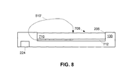
- FIG. 8 is a schematic representation of a cross section of a wireless mobile communication devices powered by the battery of FIGS 7a and b , and further depicting magnetic flux emitted from the battery;
- FIG. 9 is a schematic representation of a cross section of a wireless mobile communication devices incorporating a magnetic shield portion
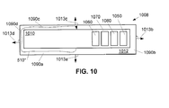
- FIG. 10 is a schematic representation of a side view of a battery incorporating a battery portion and a magnetic shield portion, the magnetic shield portion encompassing the battery portion;
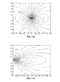
- FIGS. 11a and 11b are schematic representations of a model of a current loop representative of a battery in a mobile communication device
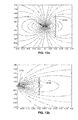
- FIGS. 12a and 12b are schematic representations of a model of a current loop representative of a battery in a mobile communication device with a magnetic shield in place;
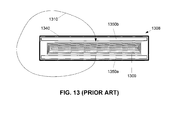
- FIG. 13 is a schematic representation of a cross section of a prior art battery incorporating structural elements
- FIG. 14 is a schematic representation of a cross section of a battery incorporating a magnetic shield portion and a structural element, the magnetic shield portion also providing structural support;
- FIG. 15 is a schematic representation of a cross section of a battery incorporating two magnetic shield portions, each magnetic shield portion also providing structural support.
- FIG. 1 is a block diagram illustrating some of the components of a wireless mobile communication device 130.
- wireless mobile communication device 130 includes a communication subsystem 200 for wireless two-way data and voice communication with the wireless network 120.
- Communication subsystem 200 may include one or more receivers, transmitters, antennas, signal processors and other components associated with wireless communications including but not limited to a radio 201.
- the particular design of the communication subsystem 200 can depend on the network in which the wireless mobile communication device 130 is intended to operate.
- the concepts herein may be applicable to a variety of wireless mobile communication devices, such as two-way pagers, cellular telephones, etc.
- network access is associated with a subscriber or user of the wireless mobile communication device 130 via a memory module 202, which may be a Subscriber Identity Module (SIM) card for use in a GSM network or a Universal Subscriber Identity Module (USIM) card for use in a Universal Mobile Telecommunication System (UMTS).
- SIM Subscriber Identity Module
- USIM Universal Subscriber Identity Module
- UMTS Universal Mobile Telecommunication System
- the SIM card is inserted in or connected to an interface 204 of the wireless mobile communication device 130 to operate in conjunction with the wireless network 120.
- the wireless mobile communication device 130 may have an integrated identity module for use with systems such as Code Division Multiple Access (CDMA) systems.
- CDMA Code Division Multiple Access
- the wireless mobile communication device 130 also includes a battery interface 206 for receiving at least one rechargeable battery 208.
- the battery 208 provides electrical power to at least some of the electrical circuitry in the wireless mobile communication device 130, and the battery interface 206 provides a mechanical and electrical connection for the battery 208.
- the time waveform (and frequency spectrum) of the Radio Frequency (RF) amplifier current within communication subsystem 200 is largely the same as that of the measured magnetic noise at the hearing aid coil.
- the communication device 130 also generally includes radio 201 (e.g. within the communication subsystem 200), a microphone 226 and the receiver 224.
- the receiver 228 can include, but is not limited to, a voice coil, a hearing aid coil and a separate T-coil.
- the wireless mobile communication device 130 may include one or more circuit boards (not shown) that implement the components described above. This disclosure is not limited to any particular electronic component or software module or any combination thereof.
- FIG. 2 shows a conventional battery 208 for powering a mobile communication device 130.
- the battery is assembled inside a case 240 and includes a positive contact pad 250, a negative contact pad 260, and may include a temperature contact pad 270 and a cryptography contact pad 280 for testing manufacturer's authenticity of the battery 208.
- the battery may include an internal microprocessor and a switch in series with the contact pads 250 and 260 which is opened by the internal microprocessor if the battery discharges below a predetermined level, in order to avoid damage to the battery. Likewise, if the battery temperature elevates beyond a predetermined level, as indicated on the temperature contact pad 270, the microprocessor may cause the switch to open.
- a sandwich electrode assembly is located within the case 240, comprising coated metallic films that according to the most common configurations are either stacked, folded back and forth like an accordion (referred to as a Z-type electrode assembly), or rolled up and flattened (referred to as a "jellyroll” electrode assembly).
- a Z-type electrode assembly stacked, folded back and forth like an accordion
- ajellyroll electrode assembly rolled up and flattened
- the exemplary prior art electrode assembly 300 comprises a positive electrode sheet 310 (cathode) and a negative electrode sheet 320 (anode) sandwiched together with a separator sheet 330 between them, and a further outer separator sheet 340 that may curl around the end of the positive electrode sheet 310 at the innermost section of the jellyroll so as to completely isolate the positive and negative electrodes.
- the separator sheet 330 contains an electrolyte, such as lithium salts, such as LiPF6, LiBF4, or LiCIO4, in an organic solvent, such as ether.
- the electrolyte may also be acid such as in a lead-acid battery, alkaline electrolyte usually potassium hydroxide in a nickel metal hydride or nickel cadmium.
- the positive electrode sheet 310 may comprise a thin sheet of aluminum (e.g. 15 ⁇ m) that is coated on both sides (e.g. 60-70 ⁇ m per side) with Lithium cobalt oxide (LiCoO2), or other suitable material, while the negative electrode sheet 320 may comprise a thin sheet of copper foil (e.g. 10 ⁇ m) that is coated on both sides with graphite (e.g. 60-70 ⁇ m per side), such that electrical current flows from the cathode to the anode.
- the separator sheet 330 e.g.
- Electrical connection between the negative electrode sheet 320 and battery contact pad 260 may be made via a conducting tab 362 that extends to an insulated feed-through (for example, as discussed below and shown schematically in FIG. 6 ) which connects to a conductive strip 360 that is insulated from the case by an insulator 370 and which extends from the feed-through to the battery contact pad 260, as shown in FIG. 4 .
- an insulated feed-through for example, as discussed below and shown schematically in FIG. 6
- a conductive strip 360 that is insulated from the case by an insulator 370 and which extends from the feed-through to the battery contact pad 260, as shown in FIG. 4 .
- Electrical connection between the positive electrode sheet 310 and battery contact pad 250 may be made either by leaving the aluminum electrode uncoated in its last roll of the jellyroll structure so as to expose the bare aluminum electrode and spot-welding, or crimping the last roll of the electrode 310 to the conductive case 240, or by spot-welding or crimping a conducting tab 352 to the case 240, thereby forming an external connection to the positive electrode through the case.
- a further conductive strip 350 may be spot-welded to an opposite side of the case from the spot-welded tab 352, or last roll of positive electrode sheet, which extends from the spot-weld on the case 240 to the battery contact pad 250, as shown in FIG. 4 .
- the positive connection to outside of the case 240 is made on the opposite side of the battery case to the negative connection, as shown in FIG. 3B .
- the positive and negative connections to outside of the case 240 it is also known in the art for the positive and negative connections to outside of the case 240 to be on the same side.
- Power is typically provided from the battery 208 to a device, such as communication device 130, via conducting pads (260, 250), as discussed above.
- a strip of conductor 350 carries the current from the conductive case 240 to the positive pad 250.
- the connection from the negative feed-through to conductive strip 360 is made on the opposite side of the battery from the positive connection.
- the conductive strip 360 carries the current from the feed-through to the negative pad 260. It will be appreciated that the arrangement of FIG. 4 results in large currents flowing externally of the battery case 240.
- connections 352 and 362 to the electrodes are made at opposite ends of the electrode assembly 300, i.e., one connection is made on the center of the jellyroll and the other on the outside of the jellyroll, current flow within the positive and negative electrode sheets 310 and 320 is in the same direction. Moreover, the magnitude of the electrode current increases from zero at the end opposite the connection to maximum at the end with the connection. Therefore, the magnitude of the current in the two electrodes as a function of position is significantly different.
- Sources of magnetic noise in the prior art battery design of FIGS. 3 and 4 include noise from the electric currents flowing in the jellyroll electrode assembly 300 and ion current in the electrolyte liquid, the connections from the electrodes 310, 320 to the feed-throughs, currents flowing in the battery case 240 and the external conductive strips 350, 360.
- FIG. 5 depicts a schematic representation of a cross-section of a battery 508, similar to battery 208, comprising a case 540 containing a battery portion 509, which in some embodiments is similar to the "jellyroll" described above with reference to FIG. 3b .
- FIG. 5 further depicts the magnetic flux 510 emitted from the battery 508 when it is in operation (for example when inserted into the battery interface 206 of communication device 130, as depicted in FIG. 6 ). It is understood that the battery portion 509 is the source of the magnetic flux 510. Indeed, FIG.
- FIG. 6 depicts the battery 508 inserted into the batter interface 206, with magnetic flux 510 passing through, and in the general area of, the receiver 224, such that when the receiver 224 is held adjacent to a hearing aid, the magnetic flux 510 will interfere with the operation of the hearing aid by decreasing the SNR of the hearing aid (e.g. noise will increase).
- FIGS. 11a and 11b Modeling of magnetic flux from a battery is provided in FIGS. 11a and 11b , described below. Modeling of magnetic field from a battery with a magnetic shield in place is provided in FIGS. 12a and 12b , described below.
- a battery 708 which comprises a battery portion 710, similar to battery 508 with like elements having like numbers, though starting with "7" rather than "2" (e.g. case 740 is similar to case 540), and a magnetic shield portion 712.
- the magnetic shield portion 712 generally comprises a high magnetic permeability material, including but not limited to Mu Metal, however other materials of suitable magnetic permeability are within the scope of present embodiments.
- the magnetic shield portion 712 is arranged relative to battery portion 710 so that the magnetic flux 510' is generally routed through the magnetic shield portion 712 such that when the battery 708 is inserted into the battery interface 206 of the communication device 130, and the battery 708 is in operation, the magnetic flux 510' is generally routed away from the receiver 224.
- at least some portion of magnetic shield portion 712 is oriented such that a normal 713 of the magnetic shield portion 712 is generally aligned in the direction of the receiver 224 when the battery 708 is inserted into the battery interface 206.
- the magnetic shield portion 712 is external to outside to the case 740, in other embodiments the magnetic shield portion 712 can be internal to the case 740 (e.g. located between the battery portion 710 and the case 740), for example see Figures 14 and 15 .
- These equations can be solved using any suitable software, including commercially available software.
- FIG. 7b depicts a perspective view of block diagram battery 708, including the battery portion 710 and the magnetic shield portion 712.
- the case 740 is not depicted in FIG. 7b , though it is understood that magnetic shield portion 712 can be either internal or external to the case 740.
- the magnetic shield portion 712 is depicted as having the same general area of the battery portion 710, it is understood that the magnetic shield portion 712 can be smaller or larger than the area of the battery portion 710, as desired, as long as there is an overall reduction in magnetic flux in the area of the receiver 224 when the battery 708 is in operation in the communications device 130 (see FIG. 8 below).
- FIGS. 8 depicts a perspective view of block diagram battery 708, including the battery portion 710 and the magnetic shield portion 712.
- magnetic shield portion 712 is depicted as being incorporated on a face of the battery portion 710 and/or the case 740, this is not to be considered particularly limiting; indeed, as described above, the magnetic shield portion 712 can be located internal or external to the case 740.
- magnetic shield portion 712 is arranged on a side of the battery portion 710 which, when inserted into communication device 130, is generally facing the receiver.
- a magnetic shield portion 912 similar to magnetic shield portion 712, is incorporated into communication device 130.
- the magnetic shield portion 912 is generally located between the battery interface 206 and the receiver such that at least one normal of the magnetic shield portion 912 is pointing in a direction of a magnetic field emitted from a battery (not depicted) inserted into battery interface 206 when the battery is in operation in the communication device 130.
- a battery not depicted
- magnetic flux will be conducted away from the receiver 224 when the battery is in operation, as in FIG. 7 .
- magnetic shield portion 912 is depicted as having the same general area of battery interface 206, it is understood that the area of the magnetic shield portion 912 can be smaller or larger than the area of the battery interface 206, as desired, as long as there is an overall reduction in magnetic flux in the area of the receiver 224.
- magnetic shield portion 912 is depicted as being incorporated into battery interface 206, this is not to be considered particularly limiting; indeed, the magnetic shield portion 912 can be located in any suitable part of communication device 130, between the battery interface 206 and receiver.
- a magnetic shield portion 912' can be incorporated into the body of the communication device 130.
- embodiments such as that depicted in FIG. 9b shield the area of the receiver 224 not only from magnetic flux emitted from a battery inserted into the battery interface 206, but from other sources of magnetic interference within the communication device 130.
- FIG. 10 depicts alternative non-limiting embodiments of a battery 1008, similar to battery 708, with like elements having like numbers, however starting with “10" rather than “7".
- the magnetic shield portion 1012 comprises a plurality of interconnected planes 1090a, 1090b, 1090c, 1090d, each having a respective normal 1013a, 1013b, 1013c, 1013d, such that the battery portion 1010 is generally encompassed by the magnetic shield portion 1012. While only four of the interconnected planes are depicted in FIG. 10 , it is understood that each side of the battery portion 1010 is associated with a respective plane of the magnetic shield portion 1012.
- the magnetic shield portion 1012 is also a generally rectangular box of proportions similar to the battery portion 1010, however with apertures there through for electrodes 1050, 1060, 1070 and 1080.
- magnetic flux 510" emitted from the battery portion 1010 when in operation is now largely contained within the magnetic shield portion 1012.
- FIGS. 11a and 11b depict magnetic field lines of a model of a current loop 1110 of radius 0.05, according to non-limiting embodiments.
- FIG. 11b is similar to FIG. 11a , but depicts only the right hand side of FIG. 11a . It is understood that each of FIGS. 11a and 11b have been modeled with arbitrary units. It is furthermore understood that the current loop depicted in FIGS. 11a and 11b can be used to model the battery 508.
- FIGS. 12a and 12b are similar to FIGS. 11a and 11b , respectively, however each of the models depicted in FIGS. 12a and 12b include a magnetic shield portion 1212a and 1212b, respectively, each similar to magnetic shield portions 712, 712, 912, described above. Furthermore, the magnetic permeability of the magnetic shield portion 1212b being greater than the magnetic permeability of the magnetic shield portion 1212a. In any event, from a comparison of FIGS. 11a and 11b , it is understood that there is a reduction in magnetic flux to the right of the magnetic shield portion 1212a.
- FIGS. 12a and 12b are similar to FIGS. 11a and 11b , respectively, however each of the models depicted in FIGS. 12a and 12b include a magnetic shield portion 1212a and 1212b, respectively, each similar to magnetic shield portions 712, 712, 912, described above. Furthermore, the magnetic permeability of the magnetic shield portion 1212b being greater than the magnetic permeability of the magnetic shield portion 12
- FIGS. 11a and 12a are understood to represent a communication device, with the current loop 1110 representative of a battery in the communication device, and the magnetic shield portion 1212a representative of a magnetic shield portion in the communication device.
- FIG. 11a represents the communication device without a magnetic shield portion
- FIG. 12a represents the communication device with a magnetic shield portion.
- a receiver of the communication device located to the right of the magnetic shield portion 1212a would experience a reduction in magnetic flux with the magnetic shield portion when compared to a communication device without the magnetic shield portion 1212a.
- a similar reduction in magnetic flux is present between FIGS. 11b and 12b ; furthermore, from a comparison of FIGS.
- the magnetic flux can be further reduced (i.e. the magnetic flux to the right of the magnetic shield portion 1212b is less than the magnetic flux to the right of the magnetic shield portion 1212a).
- FIG. 13 depicts a battery 1308, similar to the battery 508 depicted in FIG. 5 , with like elements having like numbers, however preceded by a "13" rather than a "5".
- the battery 1308 comprises a case 1340 similar to the case 540.
- the battery 1308 further comprises structural elements 1350a and 1350b.
- the case 1340 can be comprised primarily of plastic.
- the structural elements 1350a, 1350b can comprise plates made from any suitable metal, such as stainless steel and aluminum, and are of a suitable thickness to provide structural stability to the battery 1308.
- each structural element 1350a and 1350b can be the same or different thicknesses, as desired. It is understood that the structural elements 1350a, 1350b generally sandwich the battery portion 1309 inside the case 1340.
- FIG. 13 further depicts magnetic flux 1310, similar to the magnetic flux 510, emitted from the battery portion 1409, when the battery 1408 is in operation. Similar to the description of the battery 508 described above, the magnetic flux 1310 from the battery 1308 can interfere with operation of a hearing aid, by decreasing the SNR of the hearing aid (e.g. noise will increase), when the battery 1408 is in operation in the mobile communication device 130, and the receiver 224 is held adjacent to the hearing aid.
- FIG. 14 depicts a battery 1408, similar to the battery 1308, with like elements having like numbers, however preceded by a "14" rather than a "13".
- the battery 1408 comprises a case 1440 similar to the case 1340.
- the battery 1408 includes a first structural element 1450, similar to the structural element 1350a, and a magnetic shield portion 1412.
- Magnetic shield portion 1412 is similar to structural element 1350b, however magnetic shield portion 1412 generally comprises a high magnetic permeability material, similar to the magnetic shield portion 712.
- the high magnetic permeability material can include, but is not limited to, Mu Metal, and it is understood that other materials of suitable magnetic permeability are within the scope of present embodiments.
- the magnetic shield portion 1412 is on a side of the battery portion 1409 such that the magnetic flux 1410 is generally routed through the magnetic shield portion 1412 such that when the battery 1408 is inserted into the battery interface 206 of the communication device 130.
- the magnetic flux 1410 is generally routed away from the receiver 224, similar to the battery 708.
- the magnetic shield portion 1412 provides structural stability to the battery 1408, similar to the structural element 1350b, and hence the magnetic shield portion 1412 can comprise a plate made from any suitable high magnetic permeability metal, such as Mu Metal, and is of a suitable thickness to provide structural stability to the battery 1408. It is hence understood that the structural element 1450 and the magnetic shield portion 1412, generally sandwich the battery portion 1409 inside the case 1440. Hence, in general, structural element 1450 and the magnetic shield portion 1412 provide similar structural functionality to the battery 1408 as the structural element 1350a and 1350b in the battery 1308, however the magnetic shield portion 1412 further routes the magnetic flux away from the receiver 224 when the battery 1408 is in operation in the mobile communication device 130. In general, it is further understood that each of the magnetic shield portion 1412 and structural element 1450 can be the same or different thicknesses, as desired.
- FIG. 15 depicts a battery 1508, similar to the battery 1508, with like elements having like numbers, however preceded by a "15" rather than a "15".
- the battery 1508 comprises a case 1540 similar to the case 1540.
- the battery 1508 includes a first magnetic shield portion 1512a, similar to the magnetic shield portion 1412, and a second magnetic shield portion 1512b, similar to magnetic shield portion 1512.
- Magnetic shield portions 1512a and 1512b are similar to structural elements 1450a and 1450b, respectively, each of magnetic shield portions 1512a and 1512b generally comprises a high magnetic permeability material, similar to the magnetic shield portion 712.
- the high magnetic permeability material can include, but is not limited to, Mu Metal, and it is understood that other materials of suitable magnetic permeability are within the scope of present embodiments.
- the magnetic shield portions 1512a is on a side of the battery portion 1509 such that the magnetic flux 1510 is generally routed through the magnetic shield portion 1512a such that when the battery 1508 is inserted into the battery interface 206 of the communication device 140. In other words, when the battery 1508 is in operation, the magnetic flux 1510 is generally routed away from the receiver 224, similar to the battery 708.
- the magnetic shield portion 1512b also comprises a high magnetic permeability material, the magnetic flux 1510 is also routed through the magnetic shield portion 1512b. In general, as magnetic shield portions 1512a and 1512b sandwich the battery portion 1509, a significant portion of the magnetic flux 1510 is generally contained within the battery 1508.
- each of the magnetic shield portions 1512a and 1512b provides structural stability to the battery 1508, similar to the structural elements 1350a and 1350b, and hence each of the magnetic shield portions 1512a and 1512b can comprise a plate made from any suitable high magnetic permeability metal, such as Mu Metal, and are each of a suitable thickness to provide structural stability to the battery 1508.
- each of the magnetic shield portions 1512a and 1512b can be the same or different thicknesses, as desired.
- the magnetic shield portions 1512a and 1512b generally sandwich the battery portion 1509 inside the case 1540, the magnetic shield portions 1512a and 1512b provide similar structural functionality to the battery 1508 as the structural element 1350a and 1350b in the battery 1308, however the magnetic shield portions 1512a and 1512b further route the magnetic flux away from the receiver 224 when the battery 1508 is in operation in the mobile communication device 140.
Landscapes
- Chemical & Material Sciences (AREA)
- Chemical Kinetics & Catalysis (AREA)
- Electrochemistry (AREA)
- General Chemical & Material Sciences (AREA)
- Inorganic Chemistry (AREA)
- Battery Mounting, Suspending (AREA)
- Telephone Set Structure (AREA)
Abstract
Description
- The present disclosure relates generally to batteries and more particularly to a mobile communication device and battery there for characterized by low magnetic interference.
- Mobile communication devices are popular for business and personal use. Such devices include Personal Digital Assistants (PDAs), cellular phones and smart phones. These devices provide wireless two-way voice and data communication over wireless networks such as GSM/GPRS, CDPD, TDMA, iDEN Mobitex, DataTAC, EDGE or UMTS networks, and broadband networks like Bluetooth and variants of 802.11.
- It is desirable that the electromagnetic fields generated by such devices be minimized for health reasons and in order to reduce interference with other nearby electronic devices. For example, international standards on Hearing Aid Compatibility (HAC) establish a minimum signal-to-noise (SNR) ratio at the T-coil of a hearing aid (for example, see section 7.3.4 "Signal Quality" of ANSI C63.19-2007) for effective magnetic wireless coupling to the hearing aid (including hearing aids, cochlear implants, and assistive listening devices) while minimizing magnetic interference. The hearing aid compatibility requirements are generally evaluated with the hearing aid coil in close proximity to the receiver in the mobile communication device. Traditional approaches to meeting the required signal-to-noise ratio in the presence of magnetic fields generated by mobile communication devices include increasing current in the mobile communication device receiver, installing a separate T-coil within the mobile communication device, and altering current loops and circuit board traces within the mobile communication device to minimize magnetic interference.
- Magnetic noise may be generated by a battery of a mobile communication device due to current draw associated with GSM radio transmission. Accordingly, it is desirable to minimize magnetic interference from mobile communication devices in general and to minimize magnetic interference from mobile communication device batteries due to current draw on the battery.
- A first aspect of the specification provides a battery, insertable into a mobile communication device, the mobile communication device comprising a radio interconnected with a microphone and a receiver. The battery comprises a battery portion enabled to provide electrical power to the radio, the battery portion emitting a magnetic field when in operation. The battery further comprises a magnetic shield portion arranged relative to the battery portion such that magnetic flux from the battery portion is routed away from the receiver when the battery is in operation in the mobile communication device.
- The magnetic shield portion can be substantially planar.
- The magnetic shield portion can be substantially parallel to a side of the battery portion which, when inserted into the mobile communication device, is oriented towards the receiver.
- When the battery is inserted into mobile communications devicemobile communication device, the magnetic shield portion can be located substantially between the battery portion and the receiver.
- The magnetic shield portion can substantially encompass the battery portion. The magnetic shield portion can further comprise apertures for contacting the battery portion.
- The magnetic shield portion can comprise a high magnetic permeability material. The high magnetic permeability material can comprise Mu metal.
- The battery can further comprise a case, and the magnetic shield portion can be at least one of internal and external to the case. The magnetic shield portion can be internal to the case, the magnetic shield portion being planar and of a first thickness that provides structural support to the battery. The battery can further comprise a planar structural element, internal to the case, of a second thickness that provides structural support to the battery, the magnetic shield portion and the planar structural element can substantially sandwich the battery portion. The planar structural element can be enabled to route the magnetic flux there through, such that the magnetic flux is routed through the magnetic shield portion and the planar structural element.
- At least one normal of the magnetic shield portion can be oriented in a direction of the magnetic field.
- A second aspect of the specification provides a mobile communication device. The mobile communication device comprises a radio interconnected with a microphone and a receiver. The mobile communication device further comprises a magnetic shield portion for routing magnetic flux away from the receiver when the radio is in operation, the magnetic flux from sources of magnetic interference in the mobile communication device.
- The mobile communication can further comprise a battery interface for receiving a battery to provide electrical power to the radio, the battery emitting a magnetic field when the radio is in operation, wherein when the battery is inserted into the battery interface, the magnetic shield portion is located between the battery and the receiver. The magnetic shield portion can be located on a face of the battery interface.
- The magnetic shield portion can be incorporated in at least a body of the mobile communication device.
- The magnetic shield portion can comprise a high magnetic permeability material. The high magnetic permeability material can comprise Mu metal.
-
FIG. 1 is a block diagram illustrating a wireless mobile communication device in accordance with the present disclosure; -
FIG. 2 is a perspective view of a conventional battery for powering the wireless mobile communication device ofFIG. 1 ; -
FIG. 3A is a schematic representation of positive and negative electrodes of a prior art battery such as that shown inFIG. 2 , in an un-rolled configuration; -
FIG. 3B is a schematic representation of positive and negative electrodes of a prior art battery such as that shown inFIG. 2 , in a rolled-up configuration; -
FIG. 4 is a schematic representation of positive and negative contact pads of a prior art battery such as that shown inFIG. 2 ; -
FIG. 5 is a schematic representation of a cross section of a side view of a prior art battery emitting magnetic flux in operation; -
FIG. 6 is a schematic representation of a cross section of a prior art wireless mobile communication device powered by a prior art battery therein, and further depicting magnetic flux emitted from the battery; -
FIG. 7a is a schematic representation of a cross section of a battery incorporating a battery portion and a magnetic shield portion; -
FIG 7b is a schematic representation of a perspective view of a battery incorporating a battery portion and a magnetic shield portion; -
FIG. 8 is a schematic representation of a cross section of a wireless mobile communication devices powered by the battery ofFIGS 7a and b , and further depicting magnetic flux emitted from the battery; -
FIG. 9 is a schematic representation of a cross section of a wireless mobile communication devices incorporating a magnetic shield portion; -
FIG. 10 is a schematic representation of a side view of a battery incorporating a battery portion and a magnetic shield portion, the magnetic shield portion encompassing the battery portion; -
FIGS. 11a and 11b are schematic representations of a model of a current loop representative of a battery in a mobile communication device; -
FIGS. 12a and 12b are schematic representations of a model of a current loop representative of a battery in a mobile communication device with a magnetic shield in place; -
FIG. 13 is a schematic representation of a cross section of a prior art battery incorporating structural elements; -
FIG. 14 is a schematic representation of a cross section of a battery incorporating a magnetic shield portion and a structural element, the magnetic shield portion also providing structural support; and -
FIG. 15 is a schematic representation of a cross section of a battery incorporating two magnetic shield portions, each magnetic shield portion also providing structural support. -
FIG. 1 is a block diagram illustrating some of the components of a wirelessmobile communication device 130. In the embodiment depicted inFIG. 1 , wirelessmobile communication device 130 includes acommunication subsystem 200 for wireless two-way data and voice communication with thewireless network 120.Communication subsystem 200 may include one or more receivers, transmitters, antennas, signal processors and other components associated with wireless communications including but not limited to aradio 201. The particular design of thecommunication subsystem 200 can depend on the network in which the wirelessmobile communication device 130 is intended to operate. The concepts herein may be applicable to a variety of wireless mobile communication devices, such as two-way pagers, cellular telephones, etc. - In the embodiment shown in
FIG. 1 , network access is associated with a subscriber or user of the wirelessmobile communication device 130 via amemory module 202, which may be a Subscriber Identity Module (SIM) card for use in a GSM network or a Universal Subscriber Identity Module (USIM) card for use in a Universal Mobile Telecommunication System (UMTS). The SIM card is inserted in or connected to aninterface 204 of the wirelessmobile communication device 130 to operate in conjunction with thewireless network 120. Alternatively, the wirelessmobile communication device 130 may have an integrated identity module for use with systems such as Code Division Multiple Access (CDMA) systems. - The wireless
mobile communication device 130 also includes abattery interface 206 for receiving at least onerechargeable battery 208. Thebattery 208 provides electrical power to at least some of the electrical circuitry in the wirelessmobile communication device 130, and thebattery interface 206 provides a mechanical and electrical connection for thebattery 208. As discussed above and in greater detail below, it has been discovered that when themobile communication device 130 is held in close proximity to a hearing aid device (as is the case during normal cell phone usage, for example when areceiver 224 us held close to a hearing aid device) the time waveform (and frequency spectrum) of the Radio Frequency (RF) amplifier current withincommunication subsystem 200 is largely the same as that of the measured magnetic noise at the hearing aid coil. This indicates that interference problems with the hearing aid result from magnetic noise generated by currents within the communication system associated with GSM radio transmission. Through subsequent measurements and analysis, it was found that a large portion of this magnetic noise was generated by the battery, though magnetic noise can be generated by other components of thecommunication device 130. - The
communication device 130 also generally includes radio 201 (e.g. within the communication subsystem 200), amicrophone 226 and thereceiver 224. Thereceiver 228 can include, but is not limited to, a voice coil, a hearing aid coil and a separate T-coil. - The wireless
mobile communication device 130 may include one or more circuit boards (not shown) that implement the components described above. This disclosure is not limited to any particular electronic component or software module or any combination thereof. -
FIG. 2 shows aconventional battery 208 for powering amobile communication device 130. The battery is assembled inside acase 240 and includes apositive contact pad 250, anegative contact pad 260, and may include atemperature contact pad 270 and acryptography contact pad 280 for testing manufacturer's authenticity of thebattery 208. Although not shown, the battery may include an internal microprocessor and a switch in series with thecontact pads temperature contact pad 270, the microprocessor may cause the switch to open. - A sandwich electrode assembly is located within the
case 240, comprising coated metallic films that according to the most common configurations are either stacked, folded back and forth like an accordion (referred to as a Z-type electrode assembly), or rolled up and flattened (referred to as a "jellyroll" electrode assembly). Reference will be made hereinafter to the construction and design of "jellyroll" electrode assemblies, although a person of skill in the art will appreciate that the principles set forth herein apply equally to other designs and configurations of electrode assemblies. - One such "jellyroll"
electrode assembly 300 is schematically represented inFIG. 3A in its un-rolled state and inFIG. 3B in its final rolled-up state. The exemplary priorart electrode assembly 300 comprises a positive electrode sheet 310 (cathode) and a negative electrode sheet 320 (anode) sandwiched together with aseparator sheet 330 between them, and a furtherouter separator sheet 340 that may curl around the end of thepositive electrode sheet 310 at the innermost section of the jellyroll so as to completely isolate the positive and negative electrodes. Theseparator sheet 330 contains an electrolyte, such as lithium salts, such as LiPF6, LiBF4, or LiCIO4, in an organic solvent, such as ether. The electrolyte may also be acid such as in a lead-acid battery, alkaline electrolyte usually potassium hydroxide in a nickel metal hydride or nickel cadmium. Thepositive electrode sheet 310 may comprise a thin sheet of aluminum (e.g. 15µm) that is coated on both sides (e.g. 60-70µm per side) with Lithium cobalt oxide (LiCoO2), or other suitable material, while thenegative electrode sheet 320 may comprise a thin sheet of copper foil (e.g. 10µm) that is coated on both sides with graphite (e.g. 60-70µm per side), such that electrical current flows from the cathode to the anode. The separator sheet 330 (e.g. 20 µm) has openings in it that allow the electrolyte liquid to permeate between the positive andnegative electrode sheets separator sheet 330 thus physically separates the two electrode sheets while allowing ions to flow between them. Additional details of the construction of a conventional jellyroll electrode assembly may found in the prior art, as exemplified byUS Patent 7,488,553 (Tsukamoto et al ). - Electrical connection between the
negative electrode sheet 320 andbattery contact pad 260 may be made via aconducting tab 362 that extends to an insulated feed-through (for example, as discussed below and shown schematically inFIG. 6 ) which connects to aconductive strip 360 that is insulated from the case by aninsulator 370 and which extends from the feed-through to thebattery contact pad 260, as shown inFIG. 4 . Electrical connection between thepositive electrode sheet 310 andbattery contact pad 250 may be made either by leaving the aluminum electrode uncoated in its last roll of the jellyroll structure so as to expose the bare aluminum electrode and spot-welding, or crimping the last roll of theelectrode 310 to theconductive case 240, or by spot-welding or crimping aconducting tab 352 to thecase 240, thereby forming an external connection to the positive electrode through the case. A furtherconductive strip 350 may be spot-welded to an opposite side of the case from the spot-weldedtab 352, or last roll of positive electrode sheet, which extends from the spot-weld on thecase 240 to thebattery contact pad 250, as shown inFIG. 4 . In such an arrangement, the positive connection to outside of thecase 240 is made on the opposite side of the battery case to the negative connection, as shown inFIG. 3B . However, it is also known in the art for the positive and negative connections to outside of thecase 240 to be on the same side. - Power is typically provided from the
battery 208 to a device, such ascommunication device 130, via conducting pads (260, 250), as discussed above. As shown inFIG. 4 , a strip ofconductor 350 carries the current from theconductive case 240 to thepositive pad 250. The connection from the negative feed-through toconductive strip 360 is made on the opposite side of the battery from the positive connection. Theconductive strip 360 carries the current from the feed-through to thenegative pad 260. It will be appreciated that the arrangement ofFIG. 4 results in large currents flowing externally of thebattery case 240. - As shown in
FIGS. 3A and3B , if theconnections electrode assembly 300, i.e., one connection is made on the center of the jellyroll and the other on the outside of the jellyroll, current flow within the positive andnegative electrode sheets - Sources of magnetic noise in the prior art battery design of
FIGS. 3 and4 include noise from the electric currents flowing in thejellyroll electrode assembly 300 and ion current in the electrolyte liquid, the connections from theelectrodes battery case 240 and the externalconductive strips -
FIG. 5 depicts a schematic representation of a cross-section of abattery 508, similar tobattery 208, comprising acase 540 containing abattery portion 509, which in some embodiments is similar to the "jellyroll" described above with reference toFIG. 3b .FIG. 5 further depicts themagnetic flux 510 emitted from thebattery 508 when it is in operation (for example when inserted into thebattery interface 206 ofcommunication device 130, as depicted inFIG. 6 ). It is understood that thebattery portion 509 is the source of themagnetic flux 510. Indeed,FIG. 6 depicts thebattery 508 inserted into thebatter interface 206, withmagnetic flux 510 passing through, and in the general area of, thereceiver 224, such that when thereceiver 224 is held adjacent to a hearing aid, themagnetic flux 510 will interfere with the operation of the hearing aid by decreasing the SNR of the hearing aid (e.g. noise will increase). - It is furthermore understood that depictions of magnetic flux in
FIG. 5 , as well as inFIGS. 6 ,7a ,8 ,10 ,13 ,14 and 15 are approximations. Modeling of magnetic flux from a battery is provided inFIGS. 11a and 11b , described below. Modeling of magnetic field from a battery with a magnetic shield in place is provided inFIGS. 12a and 12b , described below. - As described in detail below, magnetic noise may be significantly reduced (e.g. >10 dB reduction over the prior art) by providing a magnetic shield to direct the
magnetic flux 510 away from the region of thereceiver 224. In some embodiments, as depicted in a schematic cross-section inFIG. 7a , abattery 708 is provided which comprises abattery portion 710, similar tobattery 508 with like elements having like numbers, though starting with "7" rather than "2" (e.g. case 740 is similar to case 540), and amagnetic shield portion 712. Themagnetic shield portion 712 generally comprises a high magnetic permeability material, including but not limited to Mu Metal, however other materials of suitable magnetic permeability are within the scope of present embodiments. Furthermore, themagnetic shield portion 712 is arranged relative tobattery portion 710 so that the magnetic flux 510' is generally routed through themagnetic shield portion 712 such that when thebattery 708 is inserted into thebattery interface 206 of thecommunication device 130, and thebattery 708 is in operation, the magnetic flux 510' is generally routed away from thereceiver 224. Hence, in general, at least some portion ofmagnetic shield portion 712 is oriented such that a normal 713 of themagnetic shield portion 712 is generally aligned in the direction of thereceiver 224 when thebattery 708 is inserted into thebattery interface 206. - It is understood that while in
FIG. 7 themagnetic shield portion 712 is external to outside to thecase 740, in other embodiments themagnetic shield portion 712 can be internal to the case 740 (e.g. located between thebattery portion 710 and the case 740), for example seeFigures 14 and 15 . - The thickness and geometry of the
magnetic shield portion 712 can be dependent on the geometry of the magnetic flux 510', and the position of thereceiver 224 relative to thebattery 708 when inserted into thebattery interface 206. Indeed, the thickness and geometry of themagnetic shield portion 712 can be optimized using the equations of magnetostatics:.
whereby B is magnetic flux density, H is magnetic field intensity, c is the speed of light, j is current density and µ is magnetic permeability. Equation Set 1 is then generally solved with the boundary conditions:
whereby B1 and B2 are the magnetic flux density in, respectively, a first medium 1 and an adjacent second medium 2 (e.g. medium 1 comprises the medium outside themagnetic shield portion 712 and medium 2 comprises the material of themagnetic shield portion 712, such as Mu metal); n is the normal of the interface between medium 1 and medium 2; and µ1 and µ2 are the magnetic permeabilities of medium 1 and medium 2, respectively. These equations can be solved using any suitable software, including commercially available software. -
FIG. 7b depicts a perspective view ofblock diagram battery 708, including thebattery portion 710 and themagnetic shield portion 712. For clarity, thecase 740 is not depicted inFIG. 7b , though it is understood thatmagnetic shield portion 712 can be either internal or external to thecase 740. While inFIGS. 7a and 7b , themagnetic shield portion 712 is depicted as having the same general area of thebattery portion 710, it is understood that themagnetic shield portion 712 can be smaller or larger than the area of thebattery portion 710, as desired, as long as there is an overall reduction in magnetic flux in the area of thereceiver 224 when thebattery 708 is in operation in the communications device 130 (seeFIG. 8 below). Furthermore, while inFIGS. 7a and 7b ,magnetic shield portion 712 is depicted as being incorporated on a face of thebattery portion 710 and/or thecase 740, this is not to be considered particularly limiting; indeed, as described above, themagnetic shield portion 712 can be located internal or external to thecase 740. - Turning now to
FIG. 8 , whenbattery 708 is inserted inbattery interface 206 ofcommunication device 130, the magnetic flux 510' is directed away from the general area of thereceiver 224, hence reducing interference with a hearing aid adjacent to receiver. Hence, it is understood thatmagnetic shield portion 712 is arranged on a side of thebattery portion 710 which, when inserted intocommunication device 130, is generally facing the receiver. - In alternative non-limiting embodiments, as depicted in
FIG. 9a , amagnetic shield portion 912, similar tomagnetic shield portion 712, is incorporated intocommunication device 130. Themagnetic shield portion 912 is generally located between thebattery interface 206 and the receiver such that at least one normal of themagnetic shield portion 912 is pointing in a direction of a magnetic field emitted from a battery (not depicted) inserted intobattery interface 206 when the battery is in operation in thecommunication device 130. Hence, magnetic flux will be conducted away from thereceiver 224 when the battery is in operation, as inFIG. 7 . - While in
FIG. 9 themagnetic shield portion 912 is depicted as having the same general area ofbattery interface 206, it is understood that the area of themagnetic shield portion 912 can be smaller or larger than the area of thebattery interface 206, as desired, as long as there is an overall reduction in magnetic flux in the area of thereceiver 224. Furthermore, while inFIG. 9 ,magnetic shield portion 912 is depicted as being incorporated intobattery interface 206, this is not to be considered particularly limiting; indeed, themagnetic shield portion 912 can be located in any suitable part ofcommunication device 130, between thebattery interface 206 and receiver. For example, as depicted inFIG. 9b , a magnetic shield portion 912' can be incorporated into the body of thecommunication device 130. - It is further understood that embodiments such as that depicted in
FIG. 9b shield the area of thereceiver 224 not only from magnetic flux emitted from a battery inserted into thebattery interface 206, but from other sources of magnetic interference within thecommunication device 130. - Attention is now directed to
FIG. 10 , which depicts alternative non-limiting embodiments of abattery 1008, similar tobattery 708, with like elements having like numbers, however starting with "10" rather than "7". However, in these embodiments, themagnetic shield portion 1012 comprises a plurality ofinterconnected planes battery portion 1010 is generally encompassed by themagnetic shield portion 1012. While only four of the interconnected planes are depicted inFIG. 10 , it is understood that each side of thebattery portion 1010 is associated with a respective plane of themagnetic shield portion 1012. In other words, if thebattery portion 1010 is generally a rectangular box, then themagnetic shield portion 1012 is also a generally rectangular box of proportions similar to thebattery portion 1010, however with apertures there through forelectrodes magnetic flux 510" emitted from thebattery portion 1010 when in operation, is now largely contained within themagnetic shield portion 1012. - Attention is now directed to
FIGS. 11a and 11b , which depict magnetic field lines of a model of acurrent loop 1110 of radius 0.05, according to non-limiting embodiments.FIG. 11b is similar toFIG. 11a , but depicts only the right hand side ofFIG. 11a . It is understood that each ofFIGS. 11a and 11b have been modeled with arbitrary units. It is furthermore understood that the current loop depicted inFIGS. 11a and 11b can be used to model thebattery 508. - Attention is now directed to
FIGS. 12a and 12b , which are similar toFIGS. 11a and 11b , respectively, however each of the models depicted inFIGS. 12a and 12b include amagnetic shield portion magnetic shield portions magnetic shield portion 1212b being greater than the magnetic permeability of themagnetic shield portion 1212a. In any event, from a comparison ofFIGS. 11a and 11b , it is understood that there is a reduction in magnetic flux to the right of themagnetic shield portion 1212a.FIGS. 11a and12a are understood to represent a communication device, with thecurrent loop 1110 representative of a battery in the communication device, and themagnetic shield portion 1212a representative of a magnetic shield portion in the communication device.FIG. 11a represents the communication device without a magnetic shield portion andFIG. 12a represents the communication device with a magnetic shield portion. Hence, from a comparison ofFIGS. 11a and12a , it is understood that a receiver of the communication device located to the right of themagnetic shield portion 1212a would experience a reduction in magnetic flux with the magnetic shield portion when compared to a communication device without themagnetic shield portion 1212a. Similarly, it is understood that a similar reduction in magnetic flux is present betweenFIGS. 11b and12b ; furthermore, from a comparison ofFIGS. 12a and 12b , it is understood that by increasing magnetic permeability of a magnetic shield portion, the magnetic flux can be further reduced (i.e. the magnetic flux to the right of themagnetic shield portion 1212b is less than the magnetic flux to the right of themagnetic shield portion 1212a). - Attention is now directed to
FIG. 13 , which depicts abattery 1308, similar to thebattery 508 depicted inFIG. 5 , with like elements having like numbers, however preceded by a "13" rather than a "5". For example, thebattery 1308 comprises acase 1340 similar to thecase 540. However, thebattery 1308 further comprisesstructural elements case 1340 can be comprised primarily of plastic. Hence to give thebattery 1308 structural stability, for example to meet ruggedness testing, thestructural elements battery 1308. In general, eachstructural element structural elements battery portion 1309 inside thecase 1340.FIG. 13 further depictsmagnetic flux 1310, similar to themagnetic flux 510, emitted from thebattery portion 1409, when thebattery 1408 is in operation. Similar to the description of thebattery 508 described above, themagnetic flux 1310 from thebattery 1308 can interfere with operation of a hearing aid, by decreasing the SNR of the hearing aid (e.g. noise will increase), when thebattery 1408 is in operation in themobile communication device 130, and thereceiver 224 is held adjacent to the hearing aid. - Attention is now directed to
FIG. 14 , which depicts abattery 1408, similar to thebattery 1308, with like elements having like numbers, however preceded by a "14" rather than a "13". For example, thebattery 1408 comprises acase 1440 similar to thecase 1340. However thebattery 1408 includes a firststructural element 1450, similar to thestructural element 1350a, and amagnetic shield portion 1412.Magnetic shield portion 1412 is similar tostructural element 1350b, howevermagnetic shield portion 1412 generally comprises a high magnetic permeability material, similar to themagnetic shield portion 712. The high magnetic permeability material can include, but is not limited to, Mu Metal, and it is understood that other materials of suitable magnetic permeability are within the scope of present embodiments. Furthermore, themagnetic shield portion 1412 is on a side of thebattery portion 1409 such that the magnetic flux 1410 is generally routed through themagnetic shield portion 1412 such that when thebattery 1408 is inserted into thebattery interface 206 of thecommunication device 130. In other words, when thebattery 1408 is in operation, the magnetic flux 1410 is generally routed away from thereceiver 224, similar to thebattery 708. - Furthermore, the
magnetic shield portion 1412 provides structural stability to thebattery 1408, similar to thestructural element 1350b, and hence themagnetic shield portion 1412 can comprise a plate made from any suitable high magnetic permeability metal, such as Mu Metal, and is of a suitable thickness to provide structural stability to thebattery 1408. It is hence understood that thestructural element 1450 and themagnetic shield portion 1412, generally sandwich thebattery portion 1409 inside thecase 1440. Hence, in general,structural element 1450 and themagnetic shield portion 1412 provide similar structural functionality to thebattery 1408 as thestructural element battery 1308, however themagnetic shield portion 1412 further routes the magnetic flux away from thereceiver 224 when thebattery 1408 is in operation in themobile communication device 130. In general, it is further understood that each of themagnetic shield portion 1412 andstructural element 1450 can be the same or different thicknesses, as desired. - Attention is now directed to
FIG. 15 , which depicts abattery 1508, similar to thebattery 1508, with like elements having like numbers, however preceded by a "15" rather than a "15". For example, thebattery 1508 comprises acase 1540 similar to thecase 1540. However thebattery 1508 includes a firstmagnetic shield portion 1512a, similar to themagnetic shield portion 1412, and a secondmagnetic shield portion 1512b, similar to magnetic shield portion 1512.Magnetic shield portions magnetic shield portions magnetic shield portion 712. The high magnetic permeability material can include, but is not limited to, Mu Metal, and it is understood that other materials of suitable magnetic permeability are within the scope of present embodiments. Furthermore, themagnetic shield portions 1512a is on a side of thebattery portion 1509 such that themagnetic flux 1510 is generally routed through themagnetic shield portion 1512a such that when thebattery 1508 is inserted into thebattery interface 206 of the communication device 140. In other words, when thebattery 1508 is in operation, themagnetic flux 1510 is generally routed away from thereceiver 224, similar to thebattery 708. However, as themagnetic shield portion 1512b also comprises a high magnetic permeability material, themagnetic flux 1510 is also routed through themagnetic shield portion 1512b. In general, asmagnetic shield portions battery portion 1509, a significant portion of themagnetic flux 1510 is generally contained within thebattery 1508. - Furthermore, each of the
magnetic shield portions battery 1508, similar to thestructural elements magnetic shield portions battery 1508. In general, it is further understood that each of themagnetic shield portions magnetic shield portions battery portion 1509 inside thecase 1540, themagnetic shield portions battery 1508 as thestructural element battery 1308, however themagnetic shield portions receiver 224 when thebattery 1508 is in operation in the mobile communication device 140. - Persons skilled in the art will appreciate that there are yet more alternative implementations and modifications possible for implementing the embodiments, and that the above implementations and examples are only illustrations of one or more embodiments. The scope, therefore, is only to be limited by the claims appended hereto.
Claims (15)
- A battery (708, 1008, 1408, 1508), insertable into a mobile communication device (130), said mobile communication device (130) comprising a radio (201) interconnected with a microphone (226) and a receiver (224), said battery (708, 1008, 1408, 1508) comprising:a battery (708, 1008, 1408, 1508) portion enabled to provide electrical power to said radio (201), said battery (708, 1008, 1408, 1508) portion emitting a magnetic field (510') when in operation; anda magnetic shield portion (712, 1012, 1412, 1512a, 1512b) arranged relative to said battery (708, 1008, 1408, 1508) portion such that magnetic flux from said battery (708, 1008, 1408, 1508) portion is routed away from said receiver (224) when said battery (708, 1008, 1408, 1508) is in operation in said mobile communication device (130), said magnetic shield portion (712, 1012, 1412, 1512a, 1512b) being optionally substantially planar.
- The battery (708, 1008, 1408, 1508) of claim 1, wherein said magnetic shield portion (712, 1012, 1412, 1512a) is substantially parallel to a side of said battery (708, 1008, 1408,1508) portion which, when inserted into said mobile communication device (130), is oriented towards said receiver (224).
- The battery (708,1008, 1408, 1508) of any of claims 1 or 2, wherein when said battery (708, 1008, 1408, 1508) is inserted into mobile communication device (130), said magnetic shield portion (712, 1012, 1412, 1512a) is located substantially between said battery (708, 1008, 1408, 1508) portion and said receiver (224).
- The battery (708, 1008, 1408, 1508) of any of claims 1 to 3, wherein said magnetic shield portion (1012) substantially encompasses said battery (1008) portion, said magnetic shield portion (1012) optionally comprising apertures for contacting said battery (708,1008,1408,1508) portion.
- The battery (708, 1008, 1408, 1508) of any of claims 1 to 4, wherein said magnetic shield portion (712, 1012, 1412, 1512a, 1512b) comprises a high magnetic permeability material, said high magnetic permeability material optionally comprising Mu metal.
- The battery (708, 1008, 1408, 1508) of any of claims 1 to 5, further comprising a case, and said magnetic shield portion (712, 1012, 1412, 1512a, 1512b) is at least one of internal and external to said case.
- The battery (708, 1008, 1408, 1508) of claim 6, wherein said magnetic shield portion (712, 1012, 1412, 1512a, 1512b) is internal to said case, said magnetic shield portion (712, 1012, 1412, 1512a, 1512b) being planar and of a first thickness that provides structural support to said battery (708,1008,1408,1508).
- The battery (708, 1008, 1408, 1508) of claim 7, further comprising a planar structural element, internal to said case, of a second thickness that provides structural support to said battery (708,1008,1408,1508).
- The battery (708, 1008, 1408, 1508) of claim 8, wherein said magnetic shield portion (712, 1012, 1412, 1512a, 1512b) and said planar structural element substantially sandwich said battery (708,1008,1408,1508) portion.
- The battery (708, 1008, 1408, 1508) of claim 8, wherein said planar structural element is enabled to route said magnetic flux there through, such that said magnetic flux is routed through said magnetic shield portion (712,1012,1412,1512a, 1512b) and said planar structural element.
- The battery (708, 1008, 1408, 1508) of any of claims 1 to 10, wherein at least one normal of said magnetic shield portion (712, 1012, 1412, 1512a, 1512b) is oriented in a direction of said magnetic field (510').
- A mobile communication device (130) comprising:a radio (201) interconnected with a microphone (226) and a receiver (224);a magnetic shield portion (912, 912') for routing magnetic flux away from said receiver (224) when said radio (201) is in operation, said magnetic flux from sources of magnetic interference in said mobile communication device (130).
- The mobile communication device (130) of claim 12, further comprising a battery interface (206) for receiving a battery (508) to provide electrical power to said radio (201), said battery (508) emitting a magnetic field (510) when said radio (201) is in operation, wherein when said battery (508) is inserted into said battery interface (206), said magnetic shield portion (912, 912') is located between said battery (508) and said receiver (224), and wherein said magnetic shield portion (912, 912') is optionally located on a face of said battery interface (206).
- The mobile communication device (130) of any of claims 12 or 13, wherein said magnetic shield portion (912, 912') is incorporated in at least a body of said mobile communication device (130).
- The mobile communication device (130) of any of claims 12 to 14, wherein said magnetic shield portion (912, 912') comprises a high magnetic permeability material, said high magnetic permeability material optionally comprising Mu metal.
Priority Applications (2)
| Application Number | Priority Date | Filing Date | Title |
|---|---|---|---|
| EP09165462.4A EP2276090B1 (en) | 2009-07-14 | 2009-07-14 | Low magnetic interference battery and mobile communication device |
| CA2707228A CA2707228C (en) | 2009-07-14 | 2010-06-10 | Low magnetic interference battery and mobile communication device |
Applications Claiming Priority (1)
| Application Number | Priority Date | Filing Date | Title |
|---|---|---|---|
| EP09165462.4A EP2276090B1 (en) | 2009-07-14 | 2009-07-14 | Low magnetic interference battery and mobile communication device |
Publications (2)
| Publication Number | Publication Date |
|---|---|
| EP2276090A1 true EP2276090A1 (en) | 2011-01-19 |
| EP2276090B1 EP2276090B1 (en) | 2017-10-25 |
Family
ID=41340988
Family Applications (1)
| Application Number | Title | Priority Date | Filing Date |
|---|---|---|---|
| EP09165462.4A Active EP2276090B1 (en) | 2009-07-14 | 2009-07-14 | Low magnetic interference battery and mobile communication device |
Country Status (2)
| Country | Link |
|---|---|
| EP (1) | EP2276090B1 (en) |
| CA (1) | CA2707228C (en) |
Cited By (1)
| Publication number | Priority date | Publication date | Assignee | Title |
|---|---|---|---|---|
| US8954012B2 (en) | 2012-04-16 | 2015-02-10 | Google Technology Holdings LLC | Reduction of magnetic field noise via management of current draw from a power source |
Families Citing this family (1)
| Publication number | Priority date | Publication date | Assignee | Title |
|---|---|---|---|---|
| CN116259864B (en) * | 2021-12-09 | 2025-10-31 | 北京小米移动软件有限公司 | Battery, earphone and mobile terminal |
Citations (6)
| Publication number | Priority date | Publication date | Assignee | Title |
|---|---|---|---|---|
| JP2002261894A (en) * | 2001-02-27 | 2002-09-13 | Kyocera Corp | Mobile terminal |
| JP2003067692A (en) * | 2001-08-24 | 2003-03-07 | Nippon Telegr & Teleph Corp <Ntt> | Wireless communication module and communication method using wireless communication module |
| US20070232371A1 (en) * | 2006-03-31 | 2007-10-04 | Fujitsu Limited | Radio communication apparatus |
| JP2008251283A (en) * | 2007-03-29 | 2008-10-16 | Kyocera Corp | Electronic devices and secondary batteries |
| US20080261109A1 (en) * | 2007-04-23 | 2008-10-23 | Simplo Technology Co., Ltd. | Packaging process for slim batteries and products thereof |
| US7488553B2 (en) | 2002-01-15 | 2009-02-10 | Quallion Llc | Electric storage battery construction and method of manufacture |
Family Cites Families (4)
| Publication number | Priority date | Publication date | Assignee | Title |
|---|---|---|---|---|
| JP2000077886A (en) * | 1998-08-27 | 2000-03-14 | Toshiba Corp | Small electronic equipment |
| ATE338381T1 (en) * | 2001-03-22 | 2006-09-15 | Florian Meinhard Koenig | WIRELESS PHONE WITH EMC SHIELDING |
| JP5017716B2 (en) * | 2005-12-14 | 2012-09-05 | 北川工業株式会社 | Battery case and electronic device |
| KR101023884B1 (en) * | 2009-02-18 | 2011-03-22 | 삼성에스디아이 주식회사 | Battery pack |
-
2009
- 2009-07-14 EP EP09165462.4A patent/EP2276090B1/en active Active
-
2010
- 2010-06-10 CA CA2707228A patent/CA2707228C/en active Active
Patent Citations (6)
| Publication number | Priority date | Publication date | Assignee | Title |
|---|---|---|---|---|
| JP2002261894A (en) * | 2001-02-27 | 2002-09-13 | Kyocera Corp | Mobile terminal |
| JP2003067692A (en) * | 2001-08-24 | 2003-03-07 | Nippon Telegr & Teleph Corp <Ntt> | Wireless communication module and communication method using wireless communication module |
| US7488553B2 (en) | 2002-01-15 | 2009-02-10 | Quallion Llc | Electric storage battery construction and method of manufacture |
| US20070232371A1 (en) * | 2006-03-31 | 2007-10-04 | Fujitsu Limited | Radio communication apparatus |
| JP2008251283A (en) * | 2007-03-29 | 2008-10-16 | Kyocera Corp | Electronic devices and secondary batteries |
| US20080261109A1 (en) * | 2007-04-23 | 2008-10-23 | Simplo Technology Co., Ltd. | Packaging process for slim batteries and products thereof |
Non-Patent Citations (2)
| Title |
|---|
| "BATTERY SHIELDING LABEL", IBM TECHNICAL DISCLOSURE BULLETIN, US,, vol. 40, no. 4, 1 April 1997 (1997-04-01), pages 187 - 190, XP000728308, ISSN: 0018-8689 * |
| CLARK J: "EMI/RFI SHIELDING MATERIALS considering the choice", DESIGN ENGINEERING, September 1983 (1983-09-01), London (GB), pages 29 - 35, XP001284886 * |
Cited By (1)
| Publication number | Priority date | Publication date | Assignee | Title |
|---|---|---|---|---|
| US8954012B2 (en) | 2012-04-16 | 2015-02-10 | Google Technology Holdings LLC | Reduction of magnetic field noise via management of current draw from a power source |
Also Published As
| Publication number | Publication date |
|---|---|
| CA2707228A1 (en) | 2011-01-14 |
| CA2707228C (en) | 2015-08-04 |
| EP2276090B1 (en) | 2017-10-25 |
Similar Documents
| Publication | Publication Date | Title |
|---|---|---|
| US8663823B2 (en) | Low magnetic interference battery and mobile communication device | |
| EP2454769B1 (en) | Low magnetic interference battery | |
| CA2763825C (en) | Battery for wireless mobile communication device | |
| TWI467835B (en) | Apparatus for providing electrical power | |
| EP2276090B1 (en) | Low magnetic interference battery and mobile communication device | |
| US20110262787A1 (en) | Electrochemical Cell with Reduced Magnetic Field Emission and Corresponding Devices | |
| TWI476982B (en) | Method and apparatus for a battery having low magnetic interference | |
| JP5568639B2 (en) | Low noise battery | |
| HK1165618B (en) | Low noise battery |
Legal Events
| Date | Code | Title | Description |
|---|---|---|---|
| PUAI | Public reference made under article 153(3) epc to a published international application that has entered the european phase |
Free format text: ORIGINAL CODE: 0009012 |
|
| 17P | Request for examination filed |
Effective date: 20090714 |
|
| AK | Designated contracting states |
Kind code of ref document: A1 Designated state(s): AT BE BG CH CY CZ DE DK EE ES FI FR GB GR HR HU IE IS IT LI LT LU LV MC MK MT NL NO PL PT RO SE SI SK SM TR |
|
| RAP1 | Party data changed (applicant data changed or rights of an application transferred) |
Owner name: BLACKBERRY LIMITED |
|
| RAP1 | Party data changed (applicant data changed or rights of an application transferred) |
Owner name: BLACKBERRY LIMITED |
|
| 17Q | First examination report despatched |
Effective date: 20141105 |
|
| GRAP | Despatch of communication of intention to grant a patent |
Free format text: ORIGINAL CODE: EPIDOSNIGR1 |
|
| STAA | Information on the status of an ep patent application or granted ep patent |
Free format text: STATUS: GRANT OF PATENT IS INTENDED |
|
| RIC1 | Information provided on ipc code assigned before grant |
Ipc: H04B 15/02 20060101ALN20170503BHEP Ipc: H01M 2/10 20060101ALI20170503BHEP Ipc: H01M 2/02 20060101AFI20170503BHEP Ipc: H04M 1/02 20060101ALN20170503BHEP |
|
| INTG | Intention to grant announced |
Effective date: 20170517 |
|
| GRAS | Grant fee paid |
Free format text: ORIGINAL CODE: EPIDOSNIGR3 |
|
| GRAA | (expected) grant |
Free format text: ORIGINAL CODE: 0009210 |
|
| STAA | Information on the status of an ep patent application or granted ep patent |
Free format text: STATUS: THE PATENT HAS BEEN GRANTED |
|
| AK | Designated contracting states |
Kind code of ref document: B1 Designated state(s): AT BE BG CH CY CZ DE DK EE ES FI FR GB GR HR HU IE IS IT LI LT LU LV MC MK MT NL NO PL PT RO SE SI SK SM TR |
|
| REG | Reference to a national code |
Ref country code: GB Ref legal event code: FG4D |
|
| REG | Reference to a national code |
Ref country code: CH Ref legal event code: EP |
|
| REG | Reference to a national code |
Ref country code: AT Ref legal event code: REF Ref document number: 940684 Country of ref document: AT Kind code of ref document: T Effective date: 20171115 |
|
| REG | Reference to a national code |
Ref country code: IE Ref legal event code: FG4D |
|
| REG | Reference to a national code |
Ref country code: DE Ref legal event code: R096 Ref document number: 602009048988 Country of ref document: DE |
|
| REG | Reference to a national code |
Ref country code: NL Ref legal event code: MP Effective date: 20171025 |
|
| REG | Reference to a national code |
Ref country code: LT Ref legal event code: MG4D |
|
| REG | Reference to a national code |
Ref country code: AT Ref legal event code: MK05 Ref document number: 940684 Country of ref document: AT Kind code of ref document: T Effective date: 20171025 |
|
| PG25 | Lapsed in a contracting state [announced via postgrant information from national office to epo] |
Ref country code: NL Free format text: LAPSE BECAUSE OF FAILURE TO SUBMIT A TRANSLATION OF THE DESCRIPTION OR TO PAY THE FEE WITHIN THE PRESCRIBED TIME-LIMIT Effective date: 20171025 |
|
| PG25 | Lapsed in a contracting state [announced via postgrant information from national office to epo] |
Ref country code: FI Free format text: LAPSE BECAUSE OF FAILURE TO SUBMIT A TRANSLATION OF THE DESCRIPTION OR TO PAY THE FEE WITHIN THE PRESCRIBED TIME-LIMIT Effective date: 20171025 Ref country code: SE Free format text: LAPSE BECAUSE OF FAILURE TO SUBMIT A TRANSLATION OF THE DESCRIPTION OR TO PAY THE FEE WITHIN THE PRESCRIBED TIME-LIMIT Effective date: 20171025 Ref country code: ES Free format text: LAPSE BECAUSE OF FAILURE TO SUBMIT A TRANSLATION OF THE DESCRIPTION OR TO PAY THE FEE WITHIN THE PRESCRIBED TIME-LIMIT Effective date: 20171025 Ref country code: NO Free format text: LAPSE BECAUSE OF FAILURE TO SUBMIT A TRANSLATION OF THE DESCRIPTION OR TO PAY THE FEE WITHIN THE PRESCRIBED TIME-LIMIT Effective date: 20180125 Ref country code: LT Free format text: LAPSE BECAUSE OF FAILURE TO SUBMIT A TRANSLATION OF THE DESCRIPTION OR TO PAY THE FEE WITHIN THE PRESCRIBED TIME-LIMIT Effective date: 20171025 |
|
| PG25 | Lapsed in a contracting state [announced via postgrant information from national office to epo] |
Ref country code: IS Free format text: LAPSE BECAUSE OF FAILURE TO SUBMIT A TRANSLATION OF THE DESCRIPTION OR TO PAY THE FEE WITHIN THE PRESCRIBED TIME-LIMIT Effective date: 20180225 Ref country code: GR Free format text: LAPSE BECAUSE OF FAILURE TO SUBMIT A TRANSLATION OF THE DESCRIPTION OR TO PAY THE FEE WITHIN THE PRESCRIBED TIME-LIMIT Effective date: 20180126 Ref country code: LV Free format text: LAPSE BECAUSE OF FAILURE TO SUBMIT A TRANSLATION OF THE DESCRIPTION OR TO PAY THE FEE WITHIN THE PRESCRIBED TIME-LIMIT Effective date: 20171025 Ref country code: AT Free format text: LAPSE BECAUSE OF FAILURE TO SUBMIT A TRANSLATION OF THE DESCRIPTION OR TO PAY THE FEE WITHIN THE PRESCRIBED TIME-LIMIT Effective date: 20171025 Ref country code: BG Free format text: LAPSE BECAUSE OF FAILURE TO SUBMIT A TRANSLATION OF THE DESCRIPTION OR TO PAY THE FEE WITHIN THE PRESCRIBED TIME-LIMIT Effective date: 20180125 Ref country code: HR Free format text: LAPSE BECAUSE OF FAILURE TO SUBMIT A TRANSLATION OF THE DESCRIPTION OR TO PAY THE FEE WITHIN THE PRESCRIBED TIME-LIMIT Effective date: 20171025 |
|
| REG | Reference to a national code |
Ref country code: FR Ref legal event code: PLFP Year of fee payment: 10 Ref country code: DE Ref legal event code: R097 Ref document number: 602009048988 Country of ref document: DE |
|
| PG25 | Lapsed in a contracting state [announced via postgrant information from national office to epo] |
Ref country code: SK Free format text: LAPSE BECAUSE OF FAILURE TO SUBMIT A TRANSLATION OF THE DESCRIPTION OR TO PAY THE FEE WITHIN THE PRESCRIBED TIME-LIMIT Effective date: 20171025 Ref country code: DK Free format text: LAPSE BECAUSE OF FAILURE TO SUBMIT A TRANSLATION OF THE DESCRIPTION OR TO PAY THE FEE WITHIN THE PRESCRIBED TIME-LIMIT Effective date: 20171025 Ref country code: CY Free format text: LAPSE BECAUSE OF FAILURE TO SUBMIT A TRANSLATION OF THE DESCRIPTION OR TO PAY THE FEE WITHIN THE PRESCRIBED TIME-LIMIT Effective date: 20171025 Ref country code: CZ Free format text: LAPSE BECAUSE OF FAILURE TO SUBMIT A TRANSLATION OF THE DESCRIPTION OR TO PAY THE FEE WITHIN THE PRESCRIBED TIME-LIMIT Effective date: 20171025 Ref country code: EE Free format text: LAPSE BECAUSE OF FAILURE TO SUBMIT A TRANSLATION OF THE DESCRIPTION OR TO PAY THE FEE WITHIN THE PRESCRIBED TIME-LIMIT Effective date: 20171025 |
|
| PG25 | Lapsed in a contracting state [announced via postgrant information from national office to epo] |
Ref country code: SM Free format text: LAPSE BECAUSE OF FAILURE TO SUBMIT A TRANSLATION OF THE DESCRIPTION OR TO PAY THE FEE WITHIN THE PRESCRIBED TIME-LIMIT Effective date: 20171025 Ref country code: IT Free format text: LAPSE BECAUSE OF FAILURE TO SUBMIT A TRANSLATION OF THE DESCRIPTION OR TO PAY THE FEE WITHIN THE PRESCRIBED TIME-LIMIT Effective date: 20171025 Ref country code: PL Free format text: LAPSE BECAUSE OF FAILURE TO SUBMIT A TRANSLATION OF THE DESCRIPTION OR TO PAY THE FEE WITHIN THE PRESCRIBED TIME-LIMIT Effective date: 20171025 Ref country code: RO Free format text: LAPSE BECAUSE OF FAILURE TO SUBMIT A TRANSLATION OF THE DESCRIPTION OR TO PAY THE FEE WITHIN THE PRESCRIBED TIME-LIMIT Effective date: 20171025 |
|
| PLBE | No opposition filed within time limit |
Free format text: ORIGINAL CODE: 0009261 |
|
| STAA | Information on the status of an ep patent application or granted ep patent |
Free format text: STATUS: NO OPPOSITION FILED WITHIN TIME LIMIT |
|
| 26N | No opposition filed |
Effective date: 20180726 |
|
| PG25 | Lapsed in a contracting state [announced via postgrant information from national office to epo] |
Ref country code: SI Free format text: LAPSE BECAUSE OF FAILURE TO SUBMIT A TRANSLATION OF THE DESCRIPTION OR TO PAY THE FEE WITHIN THE PRESCRIBED TIME-LIMIT Effective date: 20171025 |
|
| REG | Reference to a national code |
Ref country code: CH Ref legal event code: PL |
|
| PG25 | Lapsed in a contracting state [announced via postgrant information from national office to epo] |
Ref country code: MC Free format text: LAPSE BECAUSE OF FAILURE TO SUBMIT A TRANSLATION OF THE DESCRIPTION OR TO PAY THE FEE WITHIN THE PRESCRIBED TIME-LIMIT Effective date: 20171025 Ref country code: LU Free format text: LAPSE BECAUSE OF NON-PAYMENT OF DUE FEES Effective date: 20180714 |
|
| REG | Reference to a national code |
Ref country code: BE Ref legal event code: MM Effective date: 20180731 |
|
| REG | Reference to a national code |
Ref country code: IE Ref legal event code: MM4A |
|
| PG25 | Lapsed in a contracting state [announced via postgrant information from national office to epo] |
Ref country code: CH Free format text: LAPSE BECAUSE OF NON-PAYMENT OF DUE FEES Effective date: 20180731 Ref country code: IE Free format text: LAPSE BECAUSE OF NON-PAYMENT OF DUE FEES Effective date: 20180714 Ref country code: LI Free format text: LAPSE BECAUSE OF NON-PAYMENT OF DUE FEES Effective date: 20180731 |
|
| PG25 | Lapsed in a contracting state [announced via postgrant information from national office to epo] |
Ref country code: BE Free format text: LAPSE BECAUSE OF NON-PAYMENT OF DUE FEES Effective date: 20180731 |
|
| PG25 | Lapsed in a contracting state [announced via postgrant information from national office to epo] |
Ref country code: MT Free format text: LAPSE BECAUSE OF NON-PAYMENT OF DUE FEES Effective date: 20180714 |
|
| PG25 | Lapsed in a contracting state [announced via postgrant information from national office to epo] |
Ref country code: TR Free format text: LAPSE BECAUSE OF FAILURE TO SUBMIT A TRANSLATION OF THE DESCRIPTION OR TO PAY THE FEE WITHIN THE PRESCRIBED TIME-LIMIT Effective date: 20171025 |
|
| PG25 | Lapsed in a contracting state [announced via postgrant information from national office to epo] |
Ref country code: HU Free format text: LAPSE BECAUSE OF FAILURE TO SUBMIT A TRANSLATION OF THE DESCRIPTION OR TO PAY THE FEE WITHIN THE PRESCRIBED TIME-LIMIT; INVALID AB INITIO Effective date: 20090714 Ref country code: PT Free format text: LAPSE BECAUSE OF FAILURE TO SUBMIT A TRANSLATION OF THE DESCRIPTION OR TO PAY THE FEE WITHIN THE PRESCRIBED TIME-LIMIT Effective date: 20171025 |
|
| PG25 | Lapsed in a contracting state [announced via postgrant information from national office to epo] |
Ref country code: MK Free format text: LAPSE BECAUSE OF NON-PAYMENT OF DUE FEES Effective date: 20171025 |
|
| REG | Reference to a national code |
Ref country code: DE Ref legal event code: R079 Ref document number: 602009048988 Country of ref document: DE Free format text: PREVIOUS MAIN CLASS: H01M0002020000 Ipc: H01M0050100000 |
|
| REG | Reference to a national code |
Ref country code: DE Ref legal event code: R082 Ref document number: 602009048988 Country of ref document: DE Ref country code: DE Ref legal event code: R081 Ref document number: 602009048988 Country of ref document: DE Owner name: MALIKIE INNOVATIONS LTD., IE Free format text: FORMER OWNER: BLACKBERRY LTD., WATERLOO, ONTARIO, CA |
|
| PGFP | Annual fee paid to national office [announced via postgrant information from national office to epo] |
Ref country code: DE Payment date: 20250728 Year of fee payment: 17 |
|
| PGFP | Annual fee paid to national office [announced via postgrant information from national office to epo] |
Ref country code: GB Payment date: 20250722 Year of fee payment: 17 |
|
| PGFP | Annual fee paid to national office [announced via postgrant information from national office to epo] |
Ref country code: FR Payment date: 20250725 Year of fee payment: 17 |