EP2275849A2 - Fiber optic cable with clear buffer tubes - Google Patents
Fiber optic cable with clear buffer tubes Download PDFInfo
- Publication number
- EP2275849A2 EP2275849A2 EP10305686A EP10305686A EP2275849A2 EP 2275849 A2 EP2275849 A2 EP 2275849A2 EP 10305686 A EP10305686 A EP 10305686A EP 10305686 A EP10305686 A EP 10305686A EP 2275849 A2 EP2275849 A2 EP 2275849A2
- Authority
- EP
- European Patent Office
- Prior art keywords
- cable
- tube
- fiber
- tubes
- fibers
- Prior art date
- Legal status (The legal status is an assumption and is not a legal conclusion. Google has not performed a legal analysis and makes no representation as to the accuracy of the status listed.)
- Withdrawn
Links
Images





Classifications
-
- G—PHYSICS
- G02—OPTICS
- G02B—OPTICAL ELEMENTS, SYSTEMS OR APPARATUS
- G02B6/00—Light guides; Structural details of arrangements comprising light guides and other optical elements, e.g. couplings
- G02B6/44—Mechanical structures for providing tensile strength and external protection for fibres, e.g. optical transmission cables
- G02B6/4401—Optical cables
- G02B6/441—Optical cables built up from sub-bundles
-
- G—PHYSICS
- G02—OPTICS
- G02B—OPTICAL ELEMENTS, SYSTEMS OR APPARATUS
- G02B6/00—Light guides; Structural details of arrangements comprising light guides and other optical elements, e.g. couplings
- G02B6/44—Mechanical structures for providing tensile strength and external protection for fibres, e.g. optical transmission cables
- G02B6/4479—Manufacturing methods of optical cables
- G02B6/4484—Manufacturing methods of optical cables with desired surplus length between fibres and protection features
Definitions
- This application relates to communication cables. More particularly, this application relates to fiber optic cable design.
- Fiber optic cables such as loose tube fiber optic cables, are generally constructed with an outer jacket, one or more buffer tubes therein and one or more fibers contained within each buffer tube.
- the fibers within each buffer tube may also be further contained within a furcation tube.
- a furcation tube is a small tube that typically contains one UV coated type fiber to protect that fiber for a short distance beyond the coverage of the jacket/buffer tube after stripping.
- fiber length differential which relates to the difference in length between a buffer tube and the fiber(s) contained therein.
- an exemplary extrusion line is shown with fibers passing through an extrusion head, with a buffer tube being extruded thereon.
- the excess length is properly controlled so that the fibers in the buffer tube are substantially straight.
- the fibers may be already bent, or likely to bend on installation, beyond a 15 degree angle resulting in attenuation of signals passing there through due to light escape at the acute bending points.
- the fibers are too short the tubes and jackets need to be shortened down before the connectors can be added, which is time consuming.
- production line products of tubed optical fibers are periodically tested after production to measure excess length to ensure it is within the desired parameters. If it is not, the excess fiber length must be adjusted by altering any one or more than one of the production parameters, such as fiber payoff tension, follow-on tension (set at various drag points), fiber positioning (towards and away from the center of the tube during extrusion), etc.
- the present arrangement overcomes the drawbacks associated with the prior art and provide for clear buffer tubes within the jacket so that the fibers and/or fibers in furcation tubes, can be seen both during manufacturing as well as after production so that any issues regarding the fiber length differential may be visually identified and addressed.
- the present arrangement includes a fiber optic cable having at least one fiber, at least one buffer tube surrounding the fiber, with the fiber being loosely held within the buffer tube.
- a jacket surrounds the tube where the at least one buffer tube is constructed from an extruded transparent polymer, allowing the arrangement of the fiber within the buffer tube to be visible along the entire length of the tube.
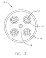
- exemplary loose tube fiber optic cables 10 from both a cross section view ( Figure 3 ) and from longitudinal cut-away views ( Figures 4-5 ).
- each of cables 10 show a plurality of fibers 12 contained within buffer tubes 14, enclosed within jacket 16.
- cable 10 has several fibers 12, within four separate buffer tubes 14 or six buffer tubes ( Figure 5 ).
- Tubes 14 are stranded in an SZ fashion around a central strength member 18, such as a GRP (glass reinforced polymer).
- Figures 3-5 are for exemplary purposes only and that the feature of this invention are applicable for any number of tubes 14 within jacket 16 as well as with a wide range of fiber 12 counts within tubes 14.
- the present arrangement is shown in SZ stranding, but is equally applicable to uni-directional helical stranding of tubes 14 around CSM (Central Strength Member) 18.
- tube 14 on the top right of cable 10 shows fibers 12 exhibiting an excess length range that is in the acceptable range, whereas fibers 12 in tube 14, located in the lower right corner, have an excessive excess length and are thus bunched up within their tube 14.
- tube 14 on the center right of cable 10 shows fibers 12 exhibiting an excess length range that is in the acceptable range, whereas fibers 12 in tube 14, located in the upper right corner, have an excessive excess length and are thus bunched up within their tube 14.
- tube 14 on the lower right of cable 10 shows fibers 12 exhibiting an excess length range that is in actually below the acceptable range and is thus fibers 12 are pressed tightly against the wall of tube 14 because of the stranding.
- a fiber length differential of 0.3% to -0.3% may be acceptable for twelve fibers 12 (depending on the fiber bend sensitivity).
- twelve fibers 12 in a 2.5 mm outer diameter tube 14 having a 1.5 mm inner diameter may need tighter excess length tolerances within 0.15 to -0.15%, to have acceptable attenuation after the tubing process.
- a fiber length differential between fibers 12 and tube 14 greater than 0.3% to 1% or -0.3% to -1% may be considered outside of the desired fiber excess length range and thus requiring adjustments to the production process to correct this issue. Adjustments to the excess fiber length may be made for example by controlling and/or shifting of the fiber length differential range during the cabling process. This is done on the fly or while the line is turned off, by adjusting payoff/carry-on tensions as well as the positioning/centering of fibers 12 during the tubing process (formation of tubes 14) as well as other common production parameters.
- Typical designs for stranded tube cables 10 account for both the 1) tensile and elongation and 2) cold temperature and shrinkage contraction direction of the tubes under various testing/operating conditions.
- fiber length differential numbers are for exemplary purposes only. It is contemplated that the features of the present application may be applied to fiber cables 10 using any desired target fiber length differential window. As an example, depending on the final use of cable 10, a higher excess length range may in fact be desirable for an aerial cable 10 because tubes 14 would be constantly under thermal stress requiring more excess fiber length. Likewise, composite cables 10 which would include other components such as conductor copper wires etc..., would also have significantly different excess length ranges for fibers 12 in tubes 14 as opposed to a purely optical cable 10.
- one of buffer tubes 14 from cable 10 are made from a transparent or transparent-translucent polymer, such as transparent/translucent HDPE (High Density Polyethylene) or other suitable clear polymer, including but not limited to (PET) polyethylene terephthalate, (PP) polypropylene, (PE) polyethylene, PVC (polyvinyl chloride; (LDPE) Low density polyethylene; and PFA (perfluoroalkoxy), having normal refractive indexes in the range of 1.3 -1.6. It is understood that polymers outside the range of a refractive index of 1.3-1.6 may be used as well provided that meet the design requirements for clear tubes 14.
- a transparent or transparent-translucent polymer such as transparent/translucent HDPE (High Density Polyethylene) or other suitable clear polymer, including but not limited to (PET) polyethylene terephthalate, (PP) polypropylene, (PE) polyethylene, PVC (polyvinyl chloride; (LDPE) Low density polyethylene; and P
- the fibers 12, either alone or within furcation tubes, may be seen directly through tubes 14.
- fibers 12/fibers 12 in furcation tubes can be visually inspected within clear buffer tubes 14, allowing manufacturers to closely monitor the fiber length differential between the length of the tubes 14 and the length of fibers 12.
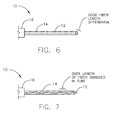
- Figure 6 shows an exemplary clear tube 14 with fibers 12 therein.
- the fiber length differential is within the acceptable limits.
- Figure 7 an exemplary clear tube 14 with fibers 12 therein is shown where the fiber length differential is not within the acceptable limits, and thus fibers 12 are unacceptably bunched up.
- clear tubes 14 allow the line processor to check if too much excessive length is present in the fibers 12 during production since they are visible directly through tubes 14. Moreover, once the line equipment is calibrated, periodic tests are required less frequently as any fiber length differential issues are visible through clear tubes 14, as a simpler indicator of such a problem.
- tubes 14 may be marked/printed in identification/label regions 20 for identification purposes. This feature can compensate for the lack of color in buffer tubes 14 which would otherwise be used for organization.
- the markings may include, but are not limited to the name of a color corresponding to a conventional tube color, an identification number associated with that conventional tube color or even printing of the marking in the color corresponding to the color code for clear tube 14.
- duplex, triplex and quad arrangements for cable 10 may be employed with various combinations of clear tubing 14 allowing the fibers 12 to be viewed directly as well as any interactions with certain intube strength members such as aramid yarns, etc...
- Such duplex, triplex and quad arrangements for tubes 14 within a cable 10 may include tear slots or V grooves 22 in each connection point leaving a tear thickness of 25% to 75% of the adjacent tube 14 thickness.
- jacket 16 may also be made from a clear polymer, allowing fibers 12 to be viewed without even stripping of jacket 16. Such an arrangement, may be useful for indoor applications where UV protection of fibers 12 is less essential.
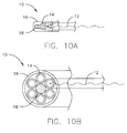
- Figure 10A shows a flat loose tube cable 10 with one tube 14 in between two reinforcing members 18 within a clear jacket 16.
- Figure 10B shows a cable 10 arranged similar to cable 10 in Figure 5 , but with a clear jacket 16. In these two arrangements, the position of strength members 18 (which are not necessarily clear) are such that their position does not interfere with the viewing of fibers 12 from the outside of cable 10 through both jacket 16 and tubes 14.
- clear polymers used for both tubes 14 and jacket 16 may include certain flame retardant (FR) additives which tend to render the these components more opaque.
- FR flame retardant
- such additives are preferably kept to a minimum for use in fields that have lower fire ratings.
- extra fire retardant additives may be used to make up for the lack thereof in tubes 14.
- clear tubes 14 of cable 10 may also provide advantages during the installation of pre-terminated cable(s) 10.
- pre-terminated type fiber optic cables 10 are common in the industry.
- a pre-terminated loose tube fiber optic cable 10 may include any number of fiber optic elements 12.
- Figure 11 shows a cable 10 having three buffer tubes 14, with twelve UV coated fiber optic elements 12 therein.
- jacket 16 covers tubes 14.
- pre-terminated cable 10 includes connectors 40 on the ends of each of the twelve fiber elements 12 in groups of one, two, three or four fibers.
- cable 10 has three tubes 14 of four fibers 12 each, with each of the four fiber elements 12 in a given tube 14, pre-terminated with one four-fiber connector 40. It is understood that many other similar combinations of pre-terminated cables 10 fall within the purview of the present arrangement.
- buffer tubes 14 are clear, allowing visual inspection of the loose fiber elements 12 therein.
- Fiber elements 12 my be independent or held within furcation tubes, depending on the desired design.
- jacket 16 is stripped away from preterminated cable 10.
- Some amount of buffer tubes 14 extend from the end, typically 5'-50' feet depending on the particular application (eg. server farms, etc). Thereafter, fiber elements 12 extend even further from the ends of tubes 14 until they reach the back end of connector 40.
- a user may place the majority of jacketed cable 10 into some subfloor or overhead tray or within a wall.
- the portion of tube 14 that extends from jacket 16 is then directed to the appropriate connection point.
- some portion of tube 14 is exposed. In the event that the length of tube 14 that is exposed is longer than necessary, this excess buffer tube is usually coiled and clipped behind the component as shown in Figure 11 .
- the excess length of fibers 12 relative to their respective buffer tubes 14, is always an issue because if there is too much excess fiber 12 within a tube 14, fibers 12 may bunch-up, bend and be subjected to attenuation problems.
- a proper excess length for the fibers 12 relative to tube 14 results in smooth uniform fiber paths and a lesser chance for attenuation.
- tubes 14 are clear, an installer may look at fibers 12 within tubes 14 during the excess tube length coiling operation to make sure that the fibers 12 therein are maintained in a smooth, relatively relaxed, arrangement. If the installer notices bunched or contorted fibers, they may unroll the coiled tube 14, check for the smoothness of the fibers 12 therein and then slowly re-roll the coil of tube 14, while checking on fibers 12 within using a larger or less tightly coiled installation arrangement to relive the fiber strain.
Landscapes
- Physics & Mathematics (AREA)
- General Physics & Mathematics (AREA)
- Optics & Photonics (AREA)
- Engineering & Computer Science (AREA)
- Manufacturing & Machinery (AREA)
- Details Of Indoor Wiring (AREA)
- Ropes Or Cables (AREA)
- Insulated Conductors (AREA)
Abstract
Description
- This application claims the benefit of priority from provisional patent application No.
61/220,784 filed on June 26, 2009 - This application relates to communication cables. More particularly, this application relates to fiber optic cable design.
- Fiber optic cables, such as loose tube fiber optic cables, are generally constructed with an outer jacket, one or more buffer tubes therein and one or more fibers contained within each buffer tube. The fibers within each buffer tube may also be further contained within a furcation tube. A furcation tube is a small tube that typically contains one UV coated type fiber to protect that fiber for a short distance beyond the coverage of the jacket/buffer tube after stripping.
- Generally, when manufacturing loose tube type fiber optic cables, one major concern is fiber length differential, which relates to the difference in length between a buffer tube and the fiber(s) contained therein.
- For example, in prior art
Figure 1 , an exemplary extrusion line is shown with fibers passing through an extrusion head, with a buffer tube being extruded thereon. In this Figure, the excess length is properly controlled so that the fibers in the buffer tube are substantially straight. - However, as shown in prior art
Figure 2 , if the production line is improperly arranged, and the fibers exhibit an excess length relative to the buffer tube, then the fibers will ultimately bunch up within the tube. This results in the fibers having excessive curves within the tube, possibly further exacerbated when the final cable is installed around various curves, resulting in signal attenuation in the fibers. - For example, if the fiber length is too excessive relative to its buffer tube, the fibers may be already bent, or likely to bend on installation, beyond a 15 degree angle resulting in attenuation of signals passing there through due to light escape at the acute bending points. As a separate issue (not shown), if the fibers are too short the tubes and jackets need to be shortened down before the connectors can be added, which is time consuming.
- In order to address this, production line products of tubed optical fibers are periodically tested after production to measure excess length to ensure it is within the desired parameters. If it is not, the excess fiber length must be adjusted by altering any one or more than one of the production parameters, such as fiber payoff tension, follow-on tension (set at various drag points), fiber positioning (towards and away from the center of the tube during extrusion), etc...).
- This process of trial and error to get the production line parameters correct, and then maintenance of the production line parameters during continuous use is time consuming.
- It is desirable to increase the ability of loose tube fiber optic cable manufacturers to be able to control fiber excess length parameters on the fly (during production) as well as to be able to visually exam fiber excess length without the need for repeated testing. Moreover, it is desirable to allow loose tube fiber optical cable installers to inspect an installation to determine if their installation has resulted in an undesirable excess fiber length.
- The present arrangement overcomes the drawbacks associated with the prior art and provide for clear buffer tubes within the jacket so that the fibers and/or fibers in furcation tubes, can be seen both during manufacturing as well as after production so that any issues regarding the fiber length differential may be visually identified and addressed.
- To this end, the present arrangement includes a fiber optic cable having at least one fiber, at least one buffer tube surrounding the fiber, with the fiber being loosely held within the buffer tube. A jacket surrounds the tube where the at least one buffer tube is constructed from an extruded transparent polymer, allowing the arrangement of the fiber within the buffer tube to be visible along the entire length of the tube.
- The present invention can be best understood through the following description and accompanying drawings, wherein:
-
Figure 1 shows a prior art fiber in tube arrangement, with appropriate fiber excess length; -
Figure 2 shows a prior art fiber in tube arrangement, with too much excess fiber length; -
Figure 3 shows sample cross section of a loose tube fiber optic cable, according to one embodiment; -
Figures 4-5 show perspective cut-away views of loose tube fiber optic cables, according to one embodiment; -
Figure 6 shows a close up view of one clear buffer tube from the loose tube fiber optic, in accordance with one embodiment; -
Figure 7 shows a close up view of one clear buffer tube from the loose tube fiber optic, in accordance with one embodiment; -
Figure 8 shows a close up view of one clear buffer tube from the loose tube fiber optic, in accordance with one embodiment; -
Figures 9A-9D shows sample cross sections of loose tube fiber optic cables, according to one embodiment; -
Figures 10A and 10B shows sample cross sections of loose tube fiber optic cables, according to one embodiment; and -
Figure 11 shows an exemplary preterminated fiber optic cable, in accordance with one embodiment. - In one embodiment as shown in
Figures 3-5 , exemplary loose tube fiberoptic cables 10 from both a cross section view (Figure 3 ) and from longitudinal cut-away views (Figures 4-5 ). - In
figures 3-5 , each ofcables 10 show a plurality offibers 12 contained withinbuffer tubes 14, enclosed withinjacket 16. For the present example,cable 10 hasseveral fibers 12, within fourseparate buffer tubes 14 or six buffer tubes (Figure 5 ). Tubes 14 are stranded in an SZ fashion around acentral strength member 18, such as a GRP (glass reinforced polymer). - Applicant first notes that
Figures 3-5 are for exemplary purposes only and that the feature of this invention are applicable for any number oftubes 14 withinjacket 16 as well as with a wide range offiber 12 counts withintubes 14. Likewise, the present arrangement is shown in SZ stranding, but is equally applicable to uni-directional helical stranding oftubes 14 around CSM (Central Strength Member) 18. - As shown in
Figure 4 ,tube 14 on the top right ofcable 10 showsfibers 12 exhibiting an excess length range that is in the acceptable range, whereasfibers 12 intube 14, located in the lower right corner, have an excessive excess length and are thus bunched up within theirtube 14. Infigure 5 , with sixtubes 14,tube 14 on the center right ofcable 10 showsfibers 12 exhibiting an excess length range that is in the acceptable range, whereasfibers 12 intube 14, located in the upper right corner, have an excessive excess length and are thus bunched up within theirtube 14. InFigure 5 ,tube 14 on the lower right ofcable 10 showsfibers 12 exhibiting an excess length range that is in actually below the acceptable range and is thusfibers 12 are pressed tightly against the wall oftube 14 because of the stranding. - Regarding the concept of an "acceptable" fiber length differential range, Applicant notes that this parameter is not a defined range for all fiber
optic cables 10. For the purposes of illustrating the salient features of the present arrangement, in acable 10, forlarger diameter tubes 14 of 3 mm in outer diameter and a 2 mm inner diameter, a fiber length differential of 0.3% to -0.3% may be acceptable for twelve fibers 12 (depending on the fiber bend sensitivity). As another example, twelvefibers 12 in a 2.5 mmouter diameter tube 14 having a 1.5 mm inner diameter may need tighter excess length tolerances within 0.15 to -0.15%, to have acceptable attenuation after the tubing process. - On the contrary, a fiber length differential between
fibers 12 andtube 14 greater than 0.3% to 1% or -0.3% to -1% may be considered outside of the desired fiber excess length range and thus requiring adjustments to the production process to correct this issue. Adjustments to the excess fiber length may be made for example by controlling and/or shifting of the fiber length differential range during the cabling process. This is done on the fly or while the line is turned off, by adjusting payoff/carry-on tensions as well as the positioning/centering offibers 12 during the tubing process (formation of tubes 14) as well as other common production parameters. - In the stranding process (where
tubes 14 are SZ or helically stranded before jacketing) the fiber excess length is altered again in either direction as per certain other factors such astube 14 lay length, outside diameter of the central strength member, payoff and carry-on tensions, temperatures etc.... Typical designs for strandedtube cables 10 account for both the 1) tensile and elongation and 2) cold temperature and shrinkage contraction direction of the tubes under various testing/operating conditions. - It is understood that that the fiber length differential numbers provided above are for exemplary purposes only. It is contemplated that the features of the present application may be applied to
fiber cables 10 using any desired target fiber length differential window. As an example, depending on the final use ofcable 10, a higher excess length range may in fact be desirable for anaerial cable 10 becausetubes 14 would be constantly under thermal stress requiring more excess fiber length. Likewise,composite cables 10 which would include other components such as conductor copper wires etc..., would also have significantly different excess length ranges forfibers 12 intubes 14 as opposed to a purelyoptical cable 10. - Turning to the structure of
tubes 14, in one embodiment, as shown inFigure 6 , one ofbuffer tubes 14 fromcable 10 are made from a transparent or transparent-translucent polymer, such as transparent/translucent HDPE (High Density Polyethylene) or other suitable clear polymer, including but not limited to (PET) polyethylene terephthalate, (PP) polypropylene, (PE) polyethylene, PVC (polyvinyl chloride; (LDPE) Low density polyethylene; and PFA (perfluoroalkoxy), having normal refractive indexes in the range of 1.3 -1.6. It is understood that polymers outside the range of a refractive index of 1.3-1.6 may be used as well provided that meet the design requirements forclear tubes 14. - In this arrangement, the
fibers 12, either alone or within furcation tubes, may be seen directly throughtubes 14. Thus, during the manufacturing process whilecable 10 is being extruded,fibers 12/fibers 12 in furcation tubes can be visually inspected withinclear buffer tubes 14, allowing manufacturers to closely monitor the fiber length differential between the length of thetubes 14 and the length offibers 12. -
Figure 6 shows an exemplaryclear tube 14 withfibers 12 therein. InFigures 6 the fiber length differential is within the acceptable limits. Conversely, inFigure 7 , an exemplaryclear tube 14 withfibers 12 therein is shown where the fiber length differential is not within the acceptable limits, and thusfibers 12 are unacceptably bunched up. - In the prior art, particularly during the manufacturing process, it was difficult to tell if
fibers 12 withintubes 14 were of an overly excessive (relative) length. Typically, to test the excess length parameter a test line run was performed and a test piece ofcable 10 was examined to measure the excess length parameter. Thereafter the extrusion/line equipment would be adjusted. This procedure may be repeated as many times as necessary. - In the present arrangement,
clear tubes 14 allow the line processor to check if too much excessive length is present in thefibers 12 during production since they are visible directly throughtubes 14. Moreover, once the line equipment is calibrated, periodic tests are required less frequently as any fiber length differential issues are visible throughclear tubes 14, as a simpler indicator of such a problem. - As an additional advantage, it is noted that larger, high
fiber count cables 10 may be produced in a less expensive manner owing to the fact that there are no coloring agents required to makebuffer tubes 14. Moreover, the lack of die in the polymer oftubes 14 is more eco-friendly and thus easier to recycle or to make from clear recycled materials. - In one embodiment, shown in
figure 8 , in order to organizefibers 12/buffer tubes 14,tubes 14 may be marked/printed in identification/label regions 20 for identification purposes. This feature can compensate for the lack of color inbuffer tubes 14 which would otherwise be used for organization. The markings may include, but are not limited to the name of a color corresponding to a conventional tube color, an identification number associated with that conventional tube color or even printing of the marking in the color corresponding to the color code forclear tube 14. - In another arrangement, as shown in
Figure 9A-9D , duplex, triplex and quad arrangements forcable 10 may be employed with various combinations ofclear tubing 14 allowing thefibers 12 to be viewed directly as well as any interactions with certain intube strength members such as aramid yarns, etc... Such duplex, triplex and quad arrangements fortubes 14 within acable 10 may include tear slots orV grooves 22 in each connection point leaving a tear thickness of 25% to 75% of theadjacent tube 14 thickness. - In another arrangement, as shown in
Figures 10A and 10B , in addition toclear tubes 14,jacket 16 may also be made from a clear polymer, allowingfibers 12 to be viewed without even stripping ofjacket 16. Such an arrangement, may be useful for indoor applications where UV protection offibers 12 is less essential.Figure 10A shows a flatloose tube cable 10 with onetube 14 in between two reinforcingmembers 18 within aclear jacket 16.Figure 10B shows acable 10 arranged similar tocable 10 inFigure 5 , but with aclear jacket 16. In these two arrangements, the position of strength members 18 (which are not necessarily clear) are such that their position does not interfere with the viewing offibers 12 from the outside ofcable 10 through bothjacket 16 andtubes 14. - It is noted that clear polymers used for both
tubes 14 andjacket 16 may include certain flame retardant (FR) additives which tend to render the these components more opaque. However, within the context of the present application, such additives are preferably kept to a minimum for use in fields that have lower fire ratings. As an alternative, whenjacket 16 is opaque andonly tubes 14 are clear polymer, then extra fire retardant additives may be used to make up for the lack thereof intubes 14. - In another embodiment , after the production advantages discussed above,
clear tubes 14 ofcable 10 may also provide advantages during the installation of pre-terminated cable(s) 10. Such pre-terminated typefiber optic cables 10 are common in the industry. A pre-terminated loose tubefiber optic cable 10 may include any number of fiberoptic elements 12. By way of example,Figure 11 shows acable 10 having threebuffer tubes 14, with twelve UV coated fiberoptic elements 12 therein. As with the above example,jacket 16covers tubes 14. - In the present arrangement illustrated in
Figure 11 ,pre-terminated cable 10 includesconnectors 40 on the ends of each of the twelvefiber elements 12 in groups of one, two, three or four fibers. In the present example shown inFigure 11 cable 10 has threetubes 14 of fourfibers 12 each, with each of the fourfiber elements 12 in a giventube 14, pre-terminated with one four-fiber connector 40. It is understood that many other similar combinations ofpre-terminated cables 10 fall within the purview of the present arrangement. - As noted above,
buffer tubes 14 are clear, allowing visual inspection of theloose fiber elements 12 therein.Fiber elements 12 my be independent or held within furcation tubes, depending on the desired design. - Typically, as shown in
Figure 11 , a portion ofjacket 16 is stripped away frompreterminated cable 10. Some amount ofbuffer tubes 14 extend from the end, typically 5'-50' feet depending on the particular application (eg. server farms, etc...). Thereafter,fiber elements 12 extend even further from the ends oftubes 14 until they reach the back end ofconnector 40. - During installation, a user may place the majority of jacketed
cable 10 into some subfloor or overhead tray or within a wall. At some point, when the desired component to be connected to is located, the portion oftube 14 that extends fromjacket 16 is then directed to the appropriate connection point. As noted above, some portion oftube 14 is exposed. In the event that the length oftube 14 that is exposed is longer than necessary, this excess buffer tube is usually coiled and clipped behind the component as shown inFigure 11 . - As noted earlier, the excess length of
fibers 12 relative to theirrespective buffer tubes 14, is always an issue because if there is too muchexcess fiber 12 within atube 14,fibers 12 may bunch-up, bend and be subjected to attenuation problems. A proper excess length for thefibers 12 relative totube 14 on the other hand results in smooth uniform fiber paths and a lesser chance for attenuation. - According to the present arrangement, because
tubes 14 are clear, an installer may look atfibers 12 withintubes 14 during the excess tube length coiling operation to make sure that thefibers 12 therein are maintained in a smooth, relatively relaxed, arrangement. If the installer notices bunched or contorted fibers, they may unroll the coiledtube 14, check for the smoothness of thefibers 12 therein and then slowly re-roll the coil oftube 14, while checking onfibers 12 within using a larger or less tightly coiled installation arrangement to relive the fiber strain. - While only certain features of the invention have been illustrated and described herein, many modifications, substitutions, changes or equivalents will now occur to those skilled in the art. It is therefore, to be understood that this application is intended to cover all such modifications and changes that fall within the true spirit of the invention.
Claims (10)
- A fiber optic cable, said cable comprising:at least one fiber;at least one buffer tube surrounding said fiber, with said fiber being loosely held within said buffer tube;a jacket surrounding said tube, wherein said at least one buffer tube is constructed from an extruded transparent polymer, allowing the arrangement of said fiber within said buffer tube to be visible along the entire length of said tube.
- The cable as claimed in claim 1, further comprising a plurality of tubes, each with a plurality of fibers therein.
- The cable as claimed in claim 2, further comprising a strength member within said jacket.
- The cable as claimed in claim 1, wherein said jacket is made of transparent polymer.
- The cable as claimed in clam 1, wherein said transparent polymer for said tubes is selected from the group consisting of transparent/translucent HDPE (High Density Polyethylene); (PET) polyethylene terephthalate; (PP) polypropylene; (PE) polyethylene, PVC (polyvinyl chloride; (LDPE) Low density polyethylene; and PFA (perfluoroalkoxy),
- The cable as claimed in clam 1, wherein said transparent polymer for said tubes has a normal refractive indexes substantially in the range of 1.3 - 1.6.
- The cable as claimed in claim 1, wherein said fibers are within said buffer tubes at a desired target range of excess length relative to a length of said buffer tube, wherein an actual amount of excess length is visible through said transparent polymer of said tubes.
- The cable as claimed in claim 1, wherein said at least one buffer tube is entirely constructed from an extruded transparent polymer, allowing the arrangement of said fiber within said buffer tube to be visible along the entire length of said tube during both manufacture and installation.
- The cable as claimed in claim 1, wherein said transparent buffer tubes include marking indicators corresponding to industry standard color markings.
- The cable as claimed in claim 9, wherein said marking indicators corresponding to industry standard color markings are made in a colored ink/dye that matches the color marking.
Applications Claiming Priority (2)
| Application Number | Priority Date | Filing Date | Title |
|---|---|---|---|
| US22078409P | 2009-06-26 | 2009-06-26 | |
| US12/816,467 US8867878B2 (en) | 2009-06-26 | 2010-06-16 | Fiber optic cable design with clear buffer tubes |
Publications (2)
| Publication Number | Publication Date |
|---|---|
| EP2275849A2 true EP2275849A2 (en) | 2011-01-19 |
| EP2275849A3 EP2275849A3 (en) | 2016-06-29 |
Family
ID=42738883
Family Applications (1)
| Application Number | Title | Priority Date | Filing Date |
|---|---|---|---|
| EP10305686.7A Withdrawn EP2275849A3 (en) | 2009-06-26 | 2010-06-25 | Fiber optic cable with clear buffer tubes |
Country Status (2)
| Country | Link |
|---|---|
| US (1) | US8867878B2 (en) |
| EP (1) | EP2275849A3 (en) |
Cited By (4)
| Publication number | Priority date | Publication date | Assignee | Title |
|---|---|---|---|---|
| NL2008847C2 (en) * | 2012-05-21 | 2013-11-25 | New Business Initiatives B V | Method for producing an assembly of a protective duct and an optical fibre cable arranged therein. |
| CN103589039A (en) * | 2013-10-29 | 2014-02-19 | 绿宝电缆(集团)有限公司 | Weatherable toughened modified polyethylene cable sheath material |
| US8923675B1 (en) | 2013-09-24 | 2014-12-30 | Corning Optical Communications LLC | Optical fiber cable with core element having surface-deposited color layer |
| CN110673285A (en) * | 2019-10-31 | 2020-01-10 | 杭州富通通信技术股份有限公司 | Invisible optical cable |
Families Citing this family (4)
| Publication number | Priority date | Publication date | Assignee | Title |
|---|---|---|---|---|
| US9715073B1 (en) * | 2015-02-19 | 2017-07-25 | Afl Telecommunications Llc | Optical trunk cable having web-connected sub-unitized configuration |
| US10725261B2 (en) | 2015-12-25 | 2020-07-28 | Fujikura Ltd. | Optical fiber-cable branch member and optical fiber-cable branch structure |
| JP2017167358A (en) * | 2016-03-16 | 2017-09-21 | 住友電気工業株式会社 | Optical fiber cable, insulated wire, heat shrinkable tube |
| KR102672071B1 (en) * | 2017-01-03 | 2024-06-05 | 삼성전자주식회사 | Optical cable and optical cable assambly having the same |
Citations (2)
| Publication number | Priority date | Publication date | Assignee | Title |
|---|---|---|---|---|
| GB2013927A (en) * | 1978-01-30 | 1979-08-15 | Telephone Cables Ltd | Manufacture of elongate optical fibre waveguide structures |
| US20090010602A1 (en) * | 2006-12-21 | 2009-01-08 | Draka Comteq B.V. | Semi-Tight Optical Fiber Unit |
Family Cites Families (9)
| Publication number | Priority date | Publication date | Assignee | Title |
|---|---|---|---|---|
| GB1479427A (en) * | 1975-02-05 | 1977-07-13 | Bicc Ltd | Opticle cables |
| US4983333A (en) * | 1989-02-16 | 1991-01-08 | Siecor Corporation | Method for controlling excess fiber length in a loose tube optical fiber buffer tube |
| JPH02226107A (en) * | 1989-02-27 | 1990-09-07 | Fujikura Ltd | Loose tube type coated optical fiber |
| US5684904A (en) * | 1996-06-10 | 1997-11-04 | Siecor Corporation | Optical cable incorporating loose buffer tubes coated with a moisture-absorptive material |
| US6404962B1 (en) * | 1999-09-15 | 2002-06-11 | Fitel Usa Corp. | Groups of optical fibers closely bound by easily removable buffer encasements, and associated fiber optic cables |
| US6442316B1 (en) * | 2000-12-21 | 2002-08-27 | Alcatel | Stress sensor based on periodically inserted color-changing tactile films to detect mishandling of fiber optic cables |
| US6915052B2 (en) * | 2003-03-06 | 2005-07-05 | E. I. Du Pont De Nemours And Company | Covered optical fiber |
| US7269318B2 (en) * | 2004-03-23 | 2007-09-11 | Superior Essex Communications, Lp | In-color fiber optic cable identification method |
| US7221831B2 (en) * | 2005-03-03 | 2007-05-22 | Nexans | Multi-tube fiber optic cable and system and method for making the same |
-
2010
- 2010-06-16 US US12/816,467 patent/US8867878B2/en active Active
- 2010-06-25 EP EP10305686.7A patent/EP2275849A3/en not_active Withdrawn
Patent Citations (2)
| Publication number | Priority date | Publication date | Assignee | Title |
|---|---|---|---|---|
| GB2013927A (en) * | 1978-01-30 | 1979-08-15 | Telephone Cables Ltd | Manufacture of elongate optical fibre waveguide structures |
| US20090010602A1 (en) * | 2006-12-21 | 2009-01-08 | Draka Comteq B.V. | Semi-Tight Optical Fiber Unit |
Cited By (6)
| Publication number | Priority date | Publication date | Assignee | Title |
|---|---|---|---|---|
| NL2008847C2 (en) * | 2012-05-21 | 2013-11-25 | New Business Initiatives B V | Method for producing an assembly of a protective duct and an optical fibre cable arranged therein. |
| US8923675B1 (en) | 2013-09-24 | 2014-12-30 | Corning Optical Communications LLC | Optical fiber cable with core element having surface-deposited color layer |
| US9435953B2 (en) | 2013-09-24 | 2016-09-06 | Corning Optical Communications LLC | Optical fiber cable with core element having surface-deposited color layer |
| CN103589039A (en) * | 2013-10-29 | 2014-02-19 | 绿宝电缆(集团)有限公司 | Weatherable toughened modified polyethylene cable sheath material |
| CN103589039B (en) * | 2013-10-29 | 2016-04-13 | 绿宝电缆(集团)有限公司 | A kind of weather-proof toughening modifying Polyethylene insulated cable sheath material |
| CN110673285A (en) * | 2019-10-31 | 2020-01-10 | 杭州富通通信技术股份有限公司 | Invisible optical cable |
Also Published As
| Publication number | Publication date |
|---|---|
| US8867878B2 (en) | 2014-10-21 |
| US20110038586A1 (en) | 2011-02-17 |
| EP2275849A3 (en) | 2016-06-29 |
Similar Documents
| Publication | Publication Date | Title |
|---|---|---|
| US8867878B2 (en) | Fiber optic cable design with clear buffer tubes | |
| EP2513695B1 (en) | Multifiber subunit cable | |
| US8855454B2 (en) | Bundled fiber optic cables | |
| US9304275B2 (en) | Micromodule cables and breakout cables therefor | |
| EP3876012B1 (en) | High fiber density, low bend loss optical fiber cable | |
| US8290321B2 (en) | Cable with features for distinguishing between fiber groups | |
| KR102469509B1 (en) | Armored flexible fiber optic assembly | |
| US5822485A (en) | Optical cable containing parallel flexible strength members and method | |
| US9915799B2 (en) | Central loose tube optical-fiber cable | |
| US6845200B1 (en) | Fiber optic assemblies, cable, and manufacturing methods therefor | |
| EP2584390A1 (en) | A central tube type optical fibre micro-cable | |
| WO2008026911A1 (en) | A loose tube optical waveguide fiber assembly | |
| EP3451036A1 (en) | Aerial drop optical waveguide cable | |
| US9195018B2 (en) | Cable with features for distinguishing between fiber groups | |
| AU2010213493B2 (en) | Duplex cables and zipcord cables and breakout cables incorporating duplex cables | |
| EP3226047B1 (en) | Single layer optical fiber cable for microduct application | |
| EP4239386B1 (en) | FIBER OPTIC CABLE WITH ELEMENTARY REINFORCEMENT ELEMENTS AND MANUFACTURING METHOD FOR THEM | |
| US20230221514A1 (en) | Optical fiber cable with different binder pitch | |
| WO2025059529A1 (en) | Ruggedized microcable for inside plant applications | |
| AU2015227475B2 (en) | Fibre optic cable subunit assemblies | |
| NZ603030B (en) | A central tube type optical fibre micro-cable |
Legal Events
| Date | Code | Title | Description |
|---|---|---|---|
| PUAI | Public reference made under article 153(3) epc to a published international application that has entered the european phase |
Free format text: ORIGINAL CODE: 0009012 |
|
| AK | Designated contracting states |
Kind code of ref document: A2 Designated state(s): AL AT BE BG CH CY CZ DE DK EE ES FI FR GB GR HR HU IE IS IT LI LT LU LV MC MK MT NL NO PL PT RO SE SI SK SM TR |
|
| AX | Request for extension of the european patent |
Extension state: BA ME RS |
|
| PUAL | Search report despatched |
Free format text: ORIGINAL CODE: 0009013 |
|
| AK | Designated contracting states |
Kind code of ref document: A3 Designated state(s): AL AT BE BG CH CY CZ DE DK EE ES FI FR GB GR HR HU IE IS IT LI LT LU LV MC MK MT NL NO PL PT RO SE SI SK SM TR |
|
| AX | Request for extension of the european patent |
Extension state: BA ME RS |
|
| RIC1 | Information provided on ipc code assigned before grant |
Ipc: G02B 6/44 20060101AFI20160523BHEP |
|
| 17P | Request for examination filed |
Effective date: 20161229 |
|
| RBV | Designated contracting states (corrected) |
Designated state(s): AL AT BE BG CH CY CZ DE DK EE ES FI FR GB GR HR HU IE IS IT LI LT LU LV MC MK MT NL NO PL PT RO SE SI SK SM TR |
|
| RAP1 | Party data changed (applicant data changed or rights of an application transferred) |
Owner name: NEXANS |
|
| 17Q | First examination report despatched |
Effective date: 20171116 |
|
| STAA | Information on the status of an ep patent application or granted ep patent |
Free format text: STATUS: THE APPLICATION IS DEEMED TO BE WITHDRAWN |
|
| 18D | Application deemed to be withdrawn |
Effective date: 20191024 |