EP2275848A2 - Fiber optic cable and furcation module - Google Patents
Fiber optic cable and furcation module Download PDFInfo
- Publication number
- EP2275848A2 EP2275848A2 EP10190349A EP10190349A EP2275848A2 EP 2275848 A2 EP2275848 A2 EP 2275848A2 EP 10190349 A EP10190349 A EP 10190349A EP 10190349 A EP10190349 A EP 10190349A EP 2275848 A2 EP2275848 A2 EP 2275848A2
- Authority
- EP
- European Patent Office
- Prior art keywords
- fiber
- optical fibre
- cable
- tubing
- optical fiber
- Prior art date
- Legal status (The legal status is an assumption and is not a legal conclusion. Google has not performed a legal analysis and makes no representation as to the accuracy of the status listed.)
- Granted
Links
- 239000000835 fiber Substances 0.000 title abstract description 182
- 239000013307 optical fiber Substances 0.000 claims abstract description 139
- 230000003287 optical effect Effects 0.000 claims description 21
- 239000000463 material Substances 0.000 abstract description 10
- 238000005452 bending Methods 0.000 abstract description 5
- 230000008602 contraction Effects 0.000 description 9
- 238000009825 accumulation Methods 0.000 description 2
- 239000000853 adhesive Substances 0.000 description 2
- 230000001070 adhesive effect Effects 0.000 description 2
- 230000003466 anti-cipated effect Effects 0.000 description 2
- 230000015572 biosynthetic process Effects 0.000 description 2
- 238000010276 construction Methods 0.000 description 2
- 238000003780 insertion Methods 0.000 description 2
- 230000037431 insertion Effects 0.000 description 2
- 238000000034 method Methods 0.000 description 2
- 229920000271 Kevlar® Polymers 0.000 description 1
- 229920006231 aramid fiber Polymers 0.000 description 1
- 238000005253 cladding Methods 0.000 description 1
- 230000006835 compression Effects 0.000 description 1
- 238000007906 compression Methods 0.000 description 1
- 239000000470 constituent Substances 0.000 description 1
- 230000000694 effects Effects 0.000 description 1
- 230000007613 environmental effect Effects 0.000 description 1
- 239000004761 kevlar Substances 0.000 description 1
- 238000004519 manufacturing process Methods 0.000 description 1
- 230000008520 organization Effects 0.000 description 1
- 238000007789 sealing Methods 0.000 description 1
Images




Classifications
-
- G—PHYSICS
- G02—OPTICS
- G02B—OPTICAL ELEMENTS, SYSTEMS OR APPARATUS
- G02B6/00—Light guides; Structural details of arrangements comprising light guides and other optical elements, e.g. couplings
- G02B6/44—Mechanical structures for providing tensile strength and external protection for fibres, e.g. optical transmission cables
- G02B6/4439—Auxiliary devices
- G02B6/444—Systems or boxes with surplus lengths
- G02B6/4453—Cassettes
-
- G—PHYSICS
- G02—OPTICS
- G02B—OPTICAL ELEMENTS, SYSTEMS OR APPARATUS
- G02B6/00—Light guides; Structural details of arrangements comprising light guides and other optical elements, e.g. couplings
- G02B6/44—Mechanical structures for providing tensile strength and external protection for fibres, e.g. optical transmission cables
- G02B6/4439—Auxiliary devices
- G02B6/444—Systems or boxes with surplus lengths
- G02B6/44528—Patch-cords; Connector arrangements in the system or in the box
-
- G—PHYSICS
- G02—OPTICS
- G02B—OPTICAL ELEMENTS, SYSTEMS OR APPARATUS
- G02B6/00—Light guides; Structural details of arrangements comprising light guides and other optical elements, e.g. couplings
- G02B6/44—Mechanical structures for providing tensile strength and external protection for fibres, e.g. optical transmission cables
- G02B6/4439—Auxiliary devices
- G02B6/4471—Terminating devices ; Cable clamps
- G02B6/44715—Fan-out devices
Definitions
- the present invention generally relates to optical fiber cable construction and furcation module construction.
- Optical fiber cables are typically composed of a variety of linear elements which are terminated and constrained linearly with respect to each other. These elements may include the optical fiber itself, tubular sheathing materials, linear strength members, and outer layers for sealing the other elements from environmental damage from rain or other moisture. Each of these elements may have different thermal coefficients of expansion. At temperatures near the ambient temperature present when the cable is assembled and terminated, the differences in thermal expansion of the various elements is not significant enough to cause any attenuation or insertion loss to optical signals being transmitted by the cable.
- Optical fiber cables may be exposed to operating temperatures up to one hundred degrees Fahrenheit removed from the ambient temperature of assembly and termination. At these temperatures, the differing degrees of elongation or contraction among the elements of the cable may damage the fiber or may cause unacceptable amounts of attenuation or insertion loss of signals being transmitted over the cable. Improvements to known optical fiber cables to address temperature-induced stresses are desirable.
- the present invention relates to an optical fiber cable assembly
- an optical fiber cable assembly comprising an optical fiber slidably enclosed within a hollow tubing, both the fiber and the tubing having corresponding first and second ends,
- the cable is terminated with the first and second ends of the tubing and the fiber constrained with respect to each other such that fiber and the tubing are approximately the same length when the cable is at a first temperature.
- the tubing is made of a material which contracts more than the optical fiber when the cable is exposed to temperatures below the first temperature, such that the fiber is longer than the tubing and excess fiber length is formed relative to the tubing.
- a fiber receiving device is provided for receiving the excess fiber length when the tubing contracts more than the fiber.
- the fiber receiving device is an intermediate portion of the tubing permits the excess fiber length to accumulate without bending in a radius smaller than a minimum bend radius.
- the present invention further relates to an optical fiber cable assembly comprising an optical fiber slidably enclosed within a hollow tubing, both the fiber and the tubing having corresponding first and second ends.
- the second ends of the fiber and the tubing are constrained with respect to each other.
- the first end of the fiber constrained beyond where the first end of the tubing is constrained.
- the cable is assembled at a first temperature and at a second lower temperature the tubing shrinks in length relative to the fiber and any excess fiber length accumulates beyond the first end of the tube.
- Optical fiber cables may be installed within telecommunications networks and exposed to the extremes of outside air temperatures. These optical fiber cables are made of a variety of materials, including but not limited to the optical fiber itself, jacketing and cladding, and strength members. Each of these constituent materials may have a different thermal coefficient of expansion, meaning that the materials will expand or contract at different rates due to temperature changes.
- the prior art optical fiber cables in FIGS. 1 to 3 show the effect of reduced temperature on an optical fiber cable 10 including an outer jacket 12 and an optical fiber 14. Fiber 14 is slidably held within a hollow opening 16 defined by jacket 12. Jacket 12 includes a first end 18 and an opposing second end 20 and fiber 14 includes corresponding first and second ends 22 and 24.
- cable 10 is exposed to a first temperature such that the ends of fiber 14 and jacket 12 are aligned with each other. If fiber 14 and jacket 12 were originally the same length at the time of their assembly, this indicates that the first temperature is approximately equal to the ambient temperature at which cable 10 was assembled.
- Cable 10 may be an optical fiber drop cable where fiber 14 is freely slidable within opening 16 of jacket 14. The first ends 18 and 22 and the second ends 20 and 24 are not fixed or constrained with respect to each in cable 10.
- Fiber 14 has a thermal coefficient of expansion which is relatively smaller than a thermal coefficient of expansion of jacket 12.
- jacket 12 has contracted much more than fiber 14.
- Ends 22 and 24 of fiber 14 extend beyond ends 18 and 20, respectively, of jacket 12.
- Ends 22 and 24 of fiber 14 are unconstrained at ends 18 and 20, respectively, and are free to move beyond ends 18 and 20, as shown.
- Ends 22 and 24 extend beyond ends 18 and 20 to define an excess length 15 of fiber 14.
- one of the first or second ends of fiber 14 and jacket 12 might be constrained with respect to each other provided the opposite ends are unconstrained and fiber 14 is freely movable within opening 16 of jacket 12.
- cable 10 is now terminated at each of the first and second ends with an optical fiber connector 26.
- optical fiber connectors are well known in the art.
- jacket 12 and fiber 14 are constrained with respect to each other. While optical fiber connector 26 may provide some degree of movement in compression of fiber 14, connector 26 does not permit fiber 14 to extend beyond connector 26.
- cable 10 is exposed to the second, lower temperature and jacket 12 has contracted to the same extent shown in FIG. 2 .
- ends 22 and 24 of fiber 14 are now constrained at ends 18 and 20 of jacket 12 by connectors 26.
- the contraction of jacket 12 compresses fiber 14 into the same length as jacket 12.
- Known materials suitable for making optical fiber 12 are essentially incompressible.
- Excess length 15 of fiber 14 is forced to fit within a shorter length of jacket 12 and is forced into a series of microbends 28 within opening 16. These microbends 28 may cause excess signal loss within cable 10. While cable 10 is shown as a single fiber cable and connectors 26 are described as fiber connectors, it is anticipated that a cable including multiple optical fibers could be substituted for cable 10 and a cable breakout at the end of such a multifiber cable could be substituted for connector 26 within the present invention.
- a cable 30 in accordance with the present invention includes a first jacket segment 32, a second jacket segment 34, fiber 14 and connectors 26 at each end. As discussed above, both fiber 14 and jackets segments 32 and 34 are constrained with respect to each other at connectors 26. Mounted between jacket segments 32 and 34 is a fiber receiving device 36. As shown, the fiber receiving device is a fiber loop box 36. Fiber 14 extends from a first connector 26 through jacket segment 32 into box 36, forms a loop 38 and then extends through jacket segment 34 to a second connector 26.
- Loop 38 of fiber 14 is sized to fit within box 36 offset from the inner surfaces 40. This will allow loop 38 to grow in size without being limited by inner surfaces 40 as excess length 15 is incorporated within loop 38.
- Box 36 should be sized to permit the formation of a loop that is greater in diameter than the minimum bend radius of fiber 14.
- FIG. 5A shows an optical fiber cable 80 similar to cable 30, with the addition of an optical device 84 such as a coupler mounted within box 36.
- Fiber 14 extends through first cable segment 32 from connector 26 into box 36 forming a loop 38 to receive excess fiber length and is constrained at optical device 84.
- a portion of the signal transmitted by fiber 14 is tapped or split into a second fiber such as a fiber 82.
- An extension 15 of fiber 14 is constrained at device 84 and extends out of box 35 through second jacket segment 34 to connector 26.
- Fiber 82 extends from device 84 out of box 36. Both fibers 15 and 82 form loops 38 within box 36 to receive excess fiber length within box 36.
- FIG. 6 shows an alternative embodiment of an optical fiber cable 46 in accordance with the present invention.
- Cable 46 includes fiber segments 32 and 34 and fiber loop box 36.
- Optical fiber 14 (shown within box 36 in hidden lines) within cable 46 is a single strand of fiber carrying a plurality of optical signals simultaneously. Segment 32 and fiber 14 within segment 32 are constrained at one end at connector 26.
- a splitter 42 is included at a second end of segment 34 of cable 46. Fiber 14 and jacket segment 34 are constrained with respect to each other at one end of splitter 42.
- fiber 14 forms a loop 38 to receive any excess fiber that might be formed when jacket segments 32 and/or 34 contract more than fiber 14.
- At an opposite end of splitter 42 are a plurality of optical fibers 44.
- Each of these fibers 44 may carry one of the plurality of optical signals from fiber 33 which has been separated from the other optical signals by splitter 42. As shown, eight optical fibers 44 extend from splitter 42. Alternatively, individual fibers 44 could be combined into a single ribbon fiber extending from splitter 42 and the individual fibers 44 broken out from the ribbon cable at a point removed from splitter 42. (Such an arrangement is shown in FIG. 12 , below.)
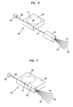
- FIG. 7 shows a further alternative embodiment of an optical fiber cable 48 including first jacket segment 32 with connector 26 at one end. Segment 32 and fiber 14 within segment 32 are constrained at connector 26. Within a fiber loop box 50 a splitter 42 is mounted so that fibers 44 extend from box 50. Fiber 14 is constrained within box 50 at splitter 42. First jacket segment is constrained at box 50 opposite from connector 26. Cable 48 does not include a second jacket segment 34 within which fiber 33 extends. A loop 38 of optical fiber within box 50 between jacket segment 32 and splitter 42 permits any excess cable length 15 due to contraction of jacket segment 32 to be absorbed without creating microbends which might create undesirable signal loss. As above, fibers 44 could be combined into a single ribbon cable and broken out into individual fibers at a point removed from box 50.
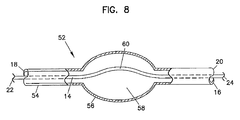
- FIG. 8 illustrates a still further alternative embodiment of an optical fiber cable 52 including a wider portion 56 of a cable jacket 54. Within portion 56 is defined an enlarged segment 58 of opening 16 through which fiber 14 extends. As described above, ends 18 and 20 of jacket 54 and ends 22 and 24 of fiber 14 are constrained with respect to each other, respectively. As jacket 54 contracts linearly when exposed to low ambient temperatures, excess fiber length 15 is collected within a curve 60 within enlarged segment 58. Segment 58 is sized to allow accumulation of the anticipated amount of excess fiber length 15 based on the overall length of cable 52 and the percentage of shrinkage calculated at the lowest ambient temperature for which cable 53 is likely to be subjected. This accumulation of excess fiber length 15 with curve 60 will avoid the problem of forcing microbending within opening 16 as shown above in FIG. 3 . Alternatively, wide portion 56 and segment 58 could be created in one or more standard sizes and the appropriate size incorporated into cable 52 depending of the length of cable 52 and a standardized lowest expected ambient temperature,
- a telecommunications module 100 is shown with an input optical fiber cable 102 and a plurality of output optical fiber holders 104 mounted to a front 106.
- Module 100 includes a housing with a top 108, a pair of opposing sides 110, a bottom 112 (shown in FIG. 12 , below), and a back 114.
- the housing defines an interior 116 (also shown in FIG. 12 , below).
- module 100 is an optical fiber splitter module, capable of separating an incoming optical fiber signal from cable 102 into up to thirty-two output optical fiber signals, each signal transmitted through an output optical fiber cable 118 terminated at an optical fiber connector 119.
- One cable 118 is shown in FIG. 10 .
- Each of the optical fiber holders 104 is adapted to hold up to eight output cables 118.
- each of the sides 110 is a mounting rail 120, adapted for mounting module 100 to a telecommunications equipment rack or similar structure.
- face 106 Adjacent sides 110, face 106 includes a pair of flanges 122 with one or more fastener openings 124. Flanges 122 and openings 124 aid with the mounting and secure fastening of module 100 to such a rack or structure.
- Each of the holders 104 includes eight openings 126, each opening 126 adapted to receive one of the output fibers 118.
- On front 106 is a space 128 for receiving indicia identifying module 100 or the cables extending to or from module 100.
- top 108 is a space for receiving a label 130, As shown, front 106 is angled with respect to back 114 to aid access to front 106 or cables 102 and 118 and to improve the cable management of these cables extending to and from module 100.
- FIG. 12 shows module 100 with top 108 removed to show routing of optical fibers within interior 116, Flanges 134 are included along sides 110 for receiving fasteners holding top 108 to module 100.
- Mounted within interior 116 along one of the sides 110 is splitter 42.
- An optical fiber 136 from cable 102 extends into interior 116 through front 106.
- Fiber 136 is formed into a loop 138 within interior 116 before being directed to a first end of splitter 42.
- An outer jacket of cable 102 is terminated at and constrained to a boot 140 attached to front 106.
- Fiber 136 extends through loop 138 to splitter 42 about interior 116 to ensure that minimum bend radius requirements to avoid excessive signal loss are maintained.
- One or more cable clips 142 are mounted to bottom 112 to aid in the layout of cable 136 within interior 116.
- Loop 138 provides a place to accumulate any such excess length 15 and avoid the creation of undesirably tight bends of fiber 136 within module 100 or cable 102.
- a plurality of ribbon cables 144 extend from splitter 42 opposite fiber 136.
- Splitter 42 separates the optical signals carried by fiber 136 into up to thirty-two individual optical signals.
- Each ribbon cable 144 may include up to eight fibers 146, each fiber carrying one of those optical signals.
- Ribbon cables 144 extend from splitter 42 to mounting holders 104 in front 106. Ribbon cables 144 form a loop 148 within interior 116 between splitter 42 and holders 104. Cable clips 142 are provided to aid in the routing and organization of loop 148 of cables 144 and cables 146 within interior 116. Loop 148 is shown in ribbon cables 144 with fibers 146 being broken out from ribbon cables 144 shortly before fibers 146 enter openings 126 of holders 104. Alternatively, individual fibers 146 could extend from splitter 42 about loop 148 with no ribbon cables included within interior 116.
- Fibers 146 are freely slidable within jackets of cables 118 and both the jacket and fibers 146 are terminated and constrained at connector 119. Cables 118 are also constrained at holders 104, as will be described further below. Fibers 146 extend through holder 104 to ribbon cables 144 and ribbon cables 144 are constrained at splitter 42. In one alternative where fibers 146 extend from holders 104 to splitter 42, fibers 146 are constrained at splitter 42. Any excess length 15 of fiber 146 within cable 118 created due to contraction of the jacket of cable 118 is accumulated within interior 116 by loop 148.
- FIG. 13 shows a generalized top view of the elements within interior 116. Only one of the ribbon cables 144 is shown completely and it should be understood that the other ribbon cables 144 are similarly constructed. At an end 145 of ribbon cable 144 individual fibers 146 are broken out. Only three fibers 146 are shown for clarity. Fibers 146 extend through an opening 126 of one of the holders 104 within a furcation tube assembly 148.
- FIG. 14 shows an inner face 105 of holder 104 with one furcation tube assembly 148 within one of the openings 126.
- Furcation tube assembly 148 includes a hollow inner tube 150 and a hollow outer tube 152.
- Outer tube 152 includes an opening within which inner tube 150 in inserted.
- Other elements may also be included within the opening of outer tube 152 about inner tube 150. These elements may include but are not limited to strength members or similar elements.
- Inner tube 150 includes an opening through which fiber 146 may be slidably inserted.
- FIGS. 15 and 16 show furcating tube assembly 148 in additional detail, including a mounting collar 154 with a front portion 153 sized to be inserted within one of the openings 126 of holder 104.
- Front portion 153 may be slightly oversized within respect to opening 126 to promote a friction fit within opening 126.
- an adhesive or some mechanical means may be used to secure mounting collar 154 within opening 126.
- Mounting collar 154 includes a central hollow opening through which inner tube 150 extends.
- a rear portion 155 of mounting collar 154 is sized to extend within the opening of outer tube 152 about inner tuber 150.
- a strength member 158 is shown in FIG. 16 extending from between inner tube 150 and outer tube 152.
- Strength member 158 as shown is an aramid fiber such as Kevlar but other suitable materials may also be used. When rear portion 155 is positioned between inner tube 150 and outer tube 152, strength member 158 is overlapped onto rear portion 155. A crimp sleeve 156 is fit about outer tube 152 above rear portion 155 of mounting collar 154 and crimped to hold these elements together. An adhesive may also be applied at location 160 where inner tube 150 extends through mounting collar 154 to ensure that inner tube 150 remains fixed within assembly 148.
- FIGS. 17 and 18 show additional details of input fiber 102 and boot 140 and their assembly to module 100.
- An opening 162 in front 105 receives an insert 164 and a threaded portion 163 of a cable mount 166 from outside module 100.
- a washer 168 and a nut 170 are placed over threaded portion 163 of mount 166 and secure mount 166 to front 106.
- an outer jacket assembly 177 for input cable 102 includes a hollow inner tube 174 with an opening to receive optical fiber 136.
- a hollow outer tube 176 is positioned about inner tube 174 and a strength member 178 is positioned between the inner and outer tubes.
- Inner tube 174 is inserted through cable mount 166 so that strength member 178 is positioned about as crimp portion of cable mount 166, A crimp sleeve 172 is positioned outer tube 176 and strength member 178 and crimped about crimp portion 165 to hold these elements together.
- Boot 140 is positioned about crimp sleeve 172 to provide strain relief and protection to cable 102 and its connection to module 100.
Landscapes
- Physics & Mathematics (AREA)
- General Physics & Mathematics (AREA)
- Optics & Photonics (AREA)
- Light Guides In General And Applications Therefor (AREA)
- Mechanical Coupling Of Light Guides (AREA)
Abstract
Description
- The present invention generally relates to optical fiber cable construction and furcation module construction.
- Optical fiber cables are typically composed of a variety of linear elements which are terminated and constrained linearly with respect to each other. These elements may include the optical fiber itself, tubular sheathing materials, linear strength members, and outer layers for sealing the other elements from environmental damage from rain or other moisture. Each of these elements may have different thermal coefficients of expansion. At temperatures near the ambient temperature present when the cable is assembled and terminated, the differences in thermal expansion of the various elements is not significant enough to cause any attenuation or insertion loss to optical signals being transmitted by the cable.
- However, as these cables are exposed to temperatures more extreme with respect to the ambient temperature at the time of assembly and termination, the differing thermal expansion coefficients may become more significant. Optical fiber cables may be exposed to operating temperatures up to one hundred degrees Fahrenheit removed from the ambient temperature of assembly and termination. At these temperatures, the differing degrees of elongation or contraction among the elements of the cable may damage the fiber or may cause unacceptable amounts of attenuation or insertion loss of signals being transmitted over the cable. Improvements to known optical fiber cables to address temperature-induced stresses are desirable.
- The present invention relates to an optical fiber cable assembly comprising an optical fiber slidably enclosed within a hollow tubing, both the fiber and the tubing having corresponding first and second ends, The cable is terminated with the first and second ends of the tubing and the fiber constrained with respect to each other such that fiber and the tubing are approximately the same length when the cable is at a first temperature. The tubing is made of a material which contracts more than the optical fiber when the cable is exposed to temperatures below the first temperature, such that the fiber is longer than the tubing and excess fiber length is formed relative to the tubing. A fiber receiving device is provided for receiving the excess fiber length when the tubing contracts more than the fiber. In one preferred embodiment, the fiber receiving device is an intermediate portion of the tubing permits the excess fiber length to accumulate without bending in a radius smaller than a minimum bend radius.
- The present invention further relates to an optical fiber cable assembly comprising an optical fiber slidably enclosed within a hollow tubing, both the fiber and the tubing having corresponding first and second ends. The second ends of the fiber and the tubing are constrained with respect to each other. The first end of the fiber constrained beyond where the first end of the tubing is constrained. The cable is assembled at a first temperature and at a second lower temperature the tubing shrinks in length relative to the fiber and any excess fiber length accumulates beyond the first end of the tube.
- The accompanying drawings, which are incorporated in and constitute a part of the specification, illustrate several aspects of the present invention and together with the description, serve to explain the principles of the invention. A brief description of the drawings is as follows:
-
FIG. 1 is a cross-sectional view of a prior art optical fiber cable segment. -
FIG. 2 is a cross-sectional view of the prior art optical fiber cable segment ofFIG. 1 at a reduced ambient temperature where the ends of the fiber and the cable jacket are not constrained with respect to each other. -
FIG. 3 is a cross-sectional view of the prior art optical fiber cable segment ofFIG. 1 at a reduced temperature where the ends of the fiber and the cable jacket are constrained with respect to each other. -
FIG. 4 is a perspective view of an optical fiber cable including a loop housing in accordance with the present invention. -
FIG. 5 is a top view of the optical fiber cable ofFIG. 4 with the top removed from the loop housing. -
FIG. 5A is a top view of an alternative embodiment of an optical fiber cable in accordance with the present invention including a coupler within a loop housing with the top removed from the housing. -
FIG. 6 is a perspective view of an optical fiber cable and splitter in accordance with the present invention. -
FIG. 7 is a perspective view of an alternative embodiment of an optical fiber cable including a loop housing and splitter mounted within the loop housing in accordance with the present invention, with the fiber and splitter within the housing shown in hidden lines. -
FIG. 8 is a side view with partial cross-section of an alternative embodiment of an optical fiber cable with in accordance with the present invention including an intermediate portion of tubing to receive excess fiber length. -
FIG. 9 is a front perspective view of an optical fiber module in accordance with the present invention. -
FIG. 10 is a top view of the optical fiber module ofFIG. 9 . -
FIG. 11 is a front view of the optical fiber module ofFIG. 9 . -
FIG. 12 is a top view of the optical fiber module ofFIG. 9 , with the top of the module removed to permit visibility of the interior of the module. -
FIG. 13 is a top view of a generalized layout of the optical fibers within the module ofFIG. 9 . -
FIG. 14 is a rear perspective view one of the optical fiber up-jacket mounting blocks from the front of the module ofFIG. 9 , with a single up-jacket tubing assembly mounted within one of the mounting openings for sheathing one of the plurality of fibers extending from splitter. -
FIG. 15 is a side view of the optical fiber up-jacket tubing assembly fromFIG. 13 . -
FIG. 16 is an exploded view of the optical fiber up-jacket tubing assembly ofFIG. 15 . -
FIG. 17 is a side view of an optical fiber up-jacket assembly for sheathing the single input fiber to the splitter. -
FIG. 18 is a rear exploded perspective view of the single input fiber extending through the front of the module ofFIG. 9 . - Reference will now be made in detail to the exemplary aspects of the present invention that are illustrated in the accompanying drawings. Wherever possible, the same reference numbers will be used throughout the drawings to refer to the same or like parts.
- Optical fiber cables may be installed within telecommunications networks and exposed to the extremes of outside air temperatures. These optical fiber cables are made of a variety of materials, including but not limited to the optical fiber itself, jacketing and cladding, and strength members. Each of these constituent materials may have a different thermal coefficient of expansion, meaning that the materials will expand or contract at different rates due to temperature changes. The prior art optical fiber cables in
FIGS. 1 to 3 show the effect of reduced temperature on anoptical fiber cable 10 including anouter jacket 12 and anoptical fiber 14. Fiber 14 is slidably held within ahollow opening 16 defined byjacket 12.Jacket 12 includes afirst end 18 and an opposingsecond end 20 andfiber 14 includes corresponding first andsecond ends - In
FIG. 1 ,cable 10 is exposed to a first temperature such that the ends offiber 14 andjacket 12 are aligned with each other. Iffiber 14 andjacket 12 were originally the same length at the time of their assembly, this indicates that the first temperature is approximately equal to the ambient temperature at whichcable 10 was assembled.Cable 10 may be an optical fiber drop cable wherefiber 14 is freely slidable within opening 16 ofjacket 14. Thefirst ends second ends cable 10. - In
FIG, 2 ,cable 10 has now been exposed to a second temperature below the first temperature. Fiber 14 has a thermal coefficient of expansion which is relatively smaller than a thermal coefficient of expansion ofjacket 12. At the second temperature,jacket 12 has contracted much more thanfiber 14. Ends 22 and 24 offiber 14 extend beyondends jacket 12. Ends 22 and 24 offiber 14 are unconstrained atends ends ends excess length 15 offiber 14. - Alternatively, one of the first or second ends of
fiber 14 andjacket 12 might be constrained with respect to each other provided the opposite ends are unconstrained andfiber 14 is freely movable within opening 16 ofjacket 12. - In
FIG. 3 ,cable 10 is now terminated at each of the first and second ends with anoptical fiber connector 26. Such optical fiber connectors are well known in the art. To terminatecable 10 atconnector 26,jacket 12 andfiber 14 are constrained with respect to each other. Whileoptical fiber connector 26 may provide some degree of movement in compression offiber 14,connector 26 does not permitfiber 14 to extend beyondconnector 26. As shown inFIG. 3 ,cable 10 is exposed to the second, lower temperature andjacket 12 has contracted to the same extent shown inFIG. 2 . InFIG. 3 , however, ends 22 and 24 offiber 14 are now constrained at ends 18 and 20 ofjacket 12 byconnectors 26. Thus, the contraction ofjacket 12compresses fiber 14 into the same length asjacket 12. Known materials suitable for makingoptical fiber 12 are essentially incompressible.Excess length 15 offiber 14 is forced to fit within a shorter length ofjacket 12 and is forced into a series ofmicrobends 28 withinopening 16. Thesemicrobends 28 may cause excess signal loss withincable 10. Whilecable 10 is shown as a single fiber cable andconnectors 26 are described as fiber connectors, it is anticipated that a cable including multiple optical fibers could be substituted forcable 10 and a cable breakout at the end of such a multifiber cable could be substituted forconnector 26 within the present invention. - Referring now to
FIGS. 4 and 5 , acable 30 in accordance with the present invention includes afirst jacket segment 32, asecond jacket segment 34,fiber 14 andconnectors 26 at each end. As discussed above, bothfiber 14 andjackets segments connectors 26. Mounted betweenjacket segments fiber receiving device 36. As shown, the fiber receiving device is afiber loop box 36.Fiber 14 extends from afirst connector 26 throughjacket segment 32 intobox 36, forms aloop 38 and then extends throughjacket segment 34 to asecond connector 26. - When
cable 30 is exposed to a range of temperatures andjacket segments fiber 14 is gathered withinbox 36.Loop 38 offiber 14 is sized to fit withinbox 36 offset from the inner surfaces 40. This will allowloop 38 to grow in size without being limited byinner surfaces 40 asexcess length 15 is incorporated withinloop 38.Box 36 should be sized to permit the formation of a loop that is greater in diameter than the minimum bend radius offiber 14. -
FIG. 5A shows anoptical fiber cable 80 similar tocable 30, with the addition of anoptical device 84 such as a coupler mounted withinbox 36.Fiber 14 extends throughfirst cable segment 32 fromconnector 26 intobox 36 forming aloop 38 to receive excess fiber length and is constrained atoptical device 84. Withindevice 84, a portion of the signal transmitted byfiber 14 is tapped or split into a second fiber such as afiber 82. Anextension 15 offiber 14 is constrained atdevice 84 and extends out of box 35 throughsecond jacket segment 34 toconnector 26.Fiber 82 extends fromdevice 84 out ofbox 36. Bothfibers form loops 38 withinbox 36 to receive excess fiber length withinbox 36. -
FIG. 6 shows an alternative embodiment of anoptical fiber cable 46 in accordance with the present invention.Cable 46 includesfiber segments fiber loop box 36. Optical fiber 14 (shown withinbox 36 in hidden lines) withincable 46 is a single strand of fiber carrying a plurality of optical signals simultaneously.Segment 32 andfiber 14 withinsegment 32 are constrained at one end atconnector 26. At a second end ofsegment 34 ofcable 46, asplitter 42 is included.Fiber 14 andjacket segment 34 are constrained with respect to each other at one end ofsplitter 42. Withinbox 36,fiber 14 forms aloop 38 to receive any excess fiber that might be formed whenjacket segments 32 and/or 34 contract more thanfiber 14. At an opposite end ofsplitter 42 are a plurality ofoptical fibers 44. Each of thesefibers 44 may carry one of the plurality of optical signals from fiber 33 which has been separated from the other optical signals bysplitter 42. As shown, eightoptical fibers 44 extend fromsplitter 42. Alternatively,individual fibers 44 could be combined into a single ribbon fiber extending fromsplitter 42 and theindividual fibers 44 broken out from the ribbon cable at a point removed fromsplitter 42. (Such an arrangement is shown inFIG. 12 , below.) -
FIG. 7 shows a further alternative embodiment of anoptical fiber cable 48 includingfirst jacket segment 32 withconnector 26 at one end.Segment 32 andfiber 14 withinsegment 32 are constrained atconnector 26. Within a fiber loop box 50 asplitter 42 is mounted so thatfibers 44 extend frombox 50.Fiber 14 is constrained withinbox 50 atsplitter 42. First jacket segment is constrained atbox 50 opposite fromconnector 26.Cable 48 does not include asecond jacket segment 34 within which fiber 33 extends. Aloop 38 of optical fiber withinbox 50 betweenjacket segment 32 andsplitter 42 permits anyexcess cable length 15 due to contraction ofjacket segment 32 to be absorbed without creating microbends which might create undesirable signal loss. As above,fibers 44 could be combined into a single ribbon cable and broken out into individual fibers at a point removed frombox 50. -
FIG. 8 illustrates a still further alternative embodiment of anoptical fiber cable 52 including awider portion 56 of acable jacket 54. Withinportion 56 is defined anenlarged segment 58 of opening 16 through whichfiber 14 extends. As described above, ends 18 and 20 ofjacket 54 and ends 22 and 24 offiber 14 are constrained with respect to each other, respectively. Asjacket 54 contracts linearly when exposed to low ambient temperatures,excess fiber length 15 is collected within acurve 60 withinenlarged segment 58.Segment 58 is sized to allow accumulation of the anticipated amount ofexcess fiber length 15 based on the overall length ofcable 52 and the percentage of shrinkage calculated at the lowest ambient temperature for which cable 53 is likely to be subjected. This accumulation ofexcess fiber length 15 withcurve 60 will avoid the problem of forcing microbending within opening 16 as shown above inFIG. 3 . Alternatively,wide portion 56 andsegment 58 could be created in one or more standard sizes and the appropriate size incorporated intocable 52 depending of the length ofcable 52 and a standardized lowest expected ambient temperature, - Referring now to
FIGS. 9 to 11 , atelecommunications module 100 is shown with an inputoptical fiber cable 102 and a plurality of outputoptical fiber holders 104 mounted to afront 106.Module 100 includes a housing with a top 108, a pair of opposingsides 110, a bottom 112 (shown inFIG. 12 , below), and aback 114. The housing defines an interior 116 (also shown inFIG. 12 , below). As shown,module 100 is an optical fiber splitter module, capable of separating an incoming optical fiber signal fromcable 102 into up to thirty-two output optical fiber signals, each signal transmitted through an outputoptical fiber cable 118 terminated at anoptical fiber connector 119. Onecable 118 is shown inFIG. 10 . Each of theoptical fiber holders 104 is adapted to hold up to eightoutput cables 118. - On each of the
sides 110 is a mountingrail 120, adapted for mountingmodule 100 to a telecommunications equipment rack or similar structure.Adjacent sides 110,face 106 includes a pair offlanges 122 with one ormore fastener openings 124.Flanges 122 andopenings 124 aid with the mounting and secure fastening ofmodule 100 to such a rack or structure. Each of theholders 104 includes eightopenings 126, each opening 126 adapted to receive one of theoutput fibers 118. Onfront 106 is aspace 128 for receivingindicia identifying module 100 or the cables extending to or frommodule 100. On top 108 is a space for receiving alabel 130, As shown,front 106 is angled with respect to back 114 to aid access tofront 106 orcables module 100. -
FIG. 12 shows module 100 with top 108 removed to show routing of optical fibers withininterior 116,Flanges 134 are included alongsides 110 for receiving fasteners holding top 108 tomodule 100. Mounted withininterior 116 along one of thesides 110 issplitter 42. Anoptical fiber 136 fromcable 102 extends intointerior 116 throughfront 106.Fiber 136 is formed into aloop 138 withininterior 116 before being directed to a first end ofsplitter 42. An outer jacket ofcable 102 is terminated at and constrained to aboot 140 attached tofront 106.Fiber 136 extends throughloop 138 tosplitter 42 aboutinterior 116 to ensure that minimum bend radius requirements to avoid excessive signal loss are maintained. One ormore cable clips 142 are mounted tobottom 112 to aid in the layout ofcable 136 withininterior 116. - Any contraction of the jacket of
cable 102 might result in the formation ofexcess length 15 offiber 136.Loop 138 provides a place to accumulate any suchexcess length 15 and avoid the creation of undesirably tight bends offiber 136 withinmodule 100 orcable 102. - A plurality of
ribbon cables 144 extend fromsplitter 42opposite fiber 136.Splitter 42 separates the optical signals carried byfiber 136 into up to thirty-two individual optical signals. Eachribbon cable 144 may include up to eightfibers 146, each fiber carrying one of those optical signals.Ribbon cables 144 extend fromsplitter 42 to mountingholders 104 infront 106.Ribbon cables 144 form aloop 148 withininterior 116 betweensplitter 42 andholders 104. Cable clips 142 are provided to aid in the routing and organization ofloop 148 ofcables 144 andcables 146 withininterior 116.Loop 148 is shown inribbon cables 144 withfibers 146 being broken out fromribbon cables 144 shortly beforefibers 146enter openings 126 ofholders 104. Alternatively,individual fibers 146 could extend fromsplitter 42 aboutloop 148 with no ribbon cables included withininterior 116. -
Fibers 146 are freely slidable within jackets ofcables 118 and both the jacket andfibers 146 are terminated and constrained atconnector 119.Cables 118 are also constrained atholders 104, as will be described further below.Fibers 146 extend throughholder 104 toribbon cables 144 andribbon cables 144 are constrained atsplitter 42. In one alternative wherefibers 146 extend fromholders 104 tosplitter 42,fibers 146 are constrained atsplitter 42. Anyexcess length 15 offiber 146 withincable 118 created due to contraction of the jacket ofcable 118 is accumulated withininterior 116 byloop 148. -
FIG. 13 shows a generalized top view of the elements withininterior 116. Only one of theribbon cables 144 is shown completely and it should be understood that theother ribbon cables 144 are similarly constructed. At anend 145 ofribbon cable 144individual fibers 146 are broken out. Only threefibers 146 are shown for clarity.Fibers 146 extend through anopening 126 of one of theholders 104 within afurcation tube assembly 148. -
FIG. 14 shows aninner face 105 ofholder 104 with onefurcation tube assembly 148 within one of theopenings 126.Furcation tube assembly 148 includes a hollowinner tube 150 and a hollowouter tube 152.Outer tube 152 includes an opening within whichinner tube 150 in inserted. Other elements may also be included within the opening ofouter tube 152 aboutinner tube 150. These elements may include but are not limited to strength members or similar elements.Inner tube 150 includes an opening through whichfiber 146 may be slidably inserted. -
FIGS. 15 and 16 show furcatingtube assembly 148 in additional detail, including a mountingcollar 154 with a front portion 153 sized to be inserted within one of theopenings 126 ofholder 104. Front portion 153 may be slightly oversized within respect to opening 126 to promote a friction fit withinopening 126. Alternatively, an adhesive or some mechanical means may be used to secure mountingcollar 154 withinopening 126. Mountingcollar 154 includes a central hollow opening through whichinner tube 150 extends. Arear portion 155 of mountingcollar 154 is sized to extend within the opening ofouter tube 152 aboutinner tuber 150. Astrength member 158 is shown inFIG. 16 extending from betweeninner tube 150 andouter tube 152.Strength member 158 as shown is an aramid fiber such as Kevlar but other suitable materials may also be used. Whenrear portion 155 is positioned betweeninner tube 150 andouter tube 152,strength member 158 is overlapped ontorear portion 155. Acrimp sleeve 156 is fit aboutouter tube 152 aboverear portion 155 of mountingcollar 154 and crimped to hold these elements together. An adhesive may also be applied atlocation 160 whereinner tube 150 extends through mountingcollar 154 to ensure thatinner tube 150 remains fixed withinassembly 148. -
FIGS. 17 and 18 show additional details ofinput fiber 102 andboot 140 and their assembly tomodule 100. Anopening 162 infront 105 receives aninsert 164 and a threadedportion 163 of acable mount 166 fromoutside module 100. Within interior 116 awasher 168 and anut 170 are placed over threadedportion 163 ofmount 166 andsecure mount 166 tofront 106. InFIG. 17 , an outer jacket assembly 177 forinput cable 102 includes a hollowinner tube 174 with an opening to receiveoptical fiber 136. A hollowouter tube 176 is positioned aboutinner tube 174 and astrength member 178 is positioned between the inner and outer tubes. -
Inner tube 174 is inserted throughcable mount 166 so thatstrength member 178 is positioned about as crimp portion ofcable mount 166, Acrimp sleeve 172 is positionedouter tube 176 andstrength member 178 and crimped aboutcrimp portion 165 to hold these elements together.Boot 140 is positioned aboutcrimp sleeve 172 to provide strain relief and protection tocable 102 and its connection tomodule 100. - The above specification, examples and data provide a complete description of the manufacture and use of the invention. Since many embodiments of the invention can be made without departing from the spirit and scope of the invention, the invention resides in the claims hereinafter appended.
- The preferred embodiments of the preceding disclosure can be summarized as follows:
- Aspect 1 is an optical fiber cable assembly comprising:
- an optical fiber slidably enclosed within a hollow tubing, both the fiber and the tubing having corresponding first and second ends;
- the cable being terminated with the first ends of the tubing and the fiber constrained with respect to each other and the second ends of the tubing and the fiber constrained with respect to each other, such that fiber and the tubing are approximately the same length when at a first temperature;
- the tubing is made of a material which contracts more than the optical fiber when the cable is exposed to temperatures below the first temperature, such that the fiber is longer than the tubing and excess fiber length is formed; and
- wherein a fiber receiving device permits the excess fiber length to accumulate without bending in a radius smaller than a minimum bend radius.
- Aspect 2 is the optical fiber cable of aspect 1, wherein the fiber receiving device includes an intermediate portion of the tubing which permits the excess fiber length to accumulate without bending in a radius smaller than a minimum bend radius.
- Aspect 3 is the optical fiber cable of aspect 1, wherein the fiber receiving device includes a box, a first and a second intennediate end of the tubing attached to the box and the fiber passing through the box.
- Aspect 4 is the optical fiber cable of aspect 3, wherein the optical fiber forms a loop within the box.
- Aspect 5 is the optical fiber cable of aspect 2, wherein the intermediate portion of the hollow tubing defines a greater inner diameter than the remainder of the tubing.
- Aspect 6 is the optical fiber cable of aspect 1, wherein the first end of the fiber and the first end of the tubing are terminated at an optical fiber connector.
- Aspect 7 is the optical fiber cable of aspect 6, wherein both dire first and second ends of the fiber and the tubing are terminated by an optical fiber connector.
- Aspect 8 is the optical fiber cable of aspect 6, wherein the second end of the fiber and the second end of the tubing are terminated at an optical signal splitter.
- Aspect 9 is an optical fiber cable assembly comprising:
- an optical fiber slidably enclosed within a hollow tubing, both the fiber and the tubing having corresponding first and second ends;
- the second ends of the fiber and the tubing terminated together and constrained with respect to each other;
- the first end of the fiber constrained beyond where the first end of the tubing is constrained;
- wherein the cable is assembled at a first temperature and at a second lower temperature the tubing shrinks in length relative to the fiber and any excess fiber length accumulates beyond the first end of the tube.
-
Aspect 10 is the optical fiber cable assembly of aspect 9, wherein the first end of the tubing is constrained at an outer wall of a housing of a module and the first end of the fiber is constrained within an interior of the module at one end of an optical component. - Aspect 11 is the optical fiber cable assembly of
aspect 10, wherein the optical component within the module is a splitter. -
Aspect 12 is the optical fiber cable assembly of aspect 11, wherein a plurality of optical fibers extend from the splitter. - Aspect 13 is the optical fiber cable assembly of aspect 9, wherein the second ends of the fiber and the tubing are constrained at an optical fiber connector.
-
Aspect 14 is the optical fiber cable assembly ofaspect 10, wherein the module further includes an input optical fiber cable, the input optical fiber with an optical fiber slidably received within a hollow tubing, the fiber and the tubing having corresponding first and second ends, the first ends of the tubing and the fiber constrained with respect to each other, the second end of the input cable tubing
constrained at a front of the module and the second end of the input cable fiber
constrained within the interior of the module at a second end of the optical component, the fiber of the input cable forming a loop within the interior which accumulates any excess length of fiber formed by a contraction of the tubing of the input cable. -
Aspect 15 is the optical fiber cable assembly ofaspect 14, wherein the contraction of the tubing of the input cable is due to a decrease in temperature. -
Aspect 16 is an optical fiber cable assembly comprising:- an optical fiber slidably enclosed within a hollow tube, both the fiber and the tube having corresponding first and second ends;
- the first ends of the fiber and the tube terminated and constrained with respect to each other;
- the second end of the tube constrained at a cable loop box with dire second end of the fiber extending into an interior of the cable loop box;
- the second end of the fiber constrained at an optical device mounted within the fiber loop box;
- the fiber formed into a loop within the fiber loop box between the second end of the tubing and the second end of the fiber;
- wherein the cable is assembled at a first temperature and at a second lower temperature the tubing shrinks in length relative to the fiber to form an excess length of fiber and any excess fiber length accumulates in the loop of fiber within the fiber loop box.
- Aspect 17 is the optical fiber cable assembly of
aspect 16, wherein the optical device is a splitter. -
Aspect 18 is the optical fiber cable assembly ofaspect 16, wherein the first ends of the fiber and the tuber are terminated at a connector. - Aspect 19 is the optical fiber cable assembly of
aspect 16, further comprising a second fiber extending from the optical device and out of the box into a second hollow tube, the second fiber and the second tube having corresponding first and second ends, the
first end of the fiber constrained at the optical device, the first end of the tube constrained at a wall of the box, the second ends of the second fiber and the second tube terminated and constrained with respect to each other, the second fiber forming a loop within the box between the first end of the fiber and the first end of the tube for receiving excess fiber length formed by the contraction of the tube. -
Aspect 20 is the optical fiber cable assembly of aspect 19, wherein the second ends of the second fiber and the second tube are terminated at an optical fiber connector. - Aspect 21 is the optical fiber cable assembly of aspect 19, wherein the optical device is a splitter and a plurality of second fibers extend from the splitter out of the box into a plurality of second tubes.
-
Aspect 22 is a method of assembling an optical fiber cable comprising:- providing an optical fiber and a hollow tubing, the tubing is made of a material which contracts more than the optical fiber when the cable is exposed to temperatures below the first temperature both the fiber and the tubing having first and second ends;
sliding die fiber within the tubing; - providing a fiber receiving device between the first ends of the fiber and the tubing and the second ends of the fiber and the tubing;
- terminating the cable with the first ends of the tubing and the fiber constrained with respect to each other and the second ends of the tubing and the fiber constrained with respect to each other, such that fiber and the tubing are approximately the same length when at a first temperature;
- exposing the cable to a second temperature lower than the first temperature and forming excess fiber length as the tubing contracts more than the fiber;
- accumulating the excess fiber within the fiber receiving device without bending in a radius smaller than a minimum bend radius.
- providing an optical fiber and a hollow tubing, the tubing is made of a material which contracts more than the optical fiber when the cable is exposed to temperatures below the first temperature both the fiber and the tubing having first and second ends;
- Aspect 23 is a method of assembling a fiber optic splitter module comprising:
- providing a splitter with at least one optical fiber extending from opposing ends of the splitter, each of the optical fibers having a first end constrained
at the splitter and an opposing second end;
placing the splitter within an interior of a housing; - forming each optical fiber into a loop within the housing and extending the second end outside of the housing;
- sliding a hollow tube over the second end of each optical fiber such that a first end of each tube is constrained at an outer wall of the housing and a second end of each tube is adjacent the second end of the fiber within the tube;
- terminating constraining with respect to each other the second ends of the tubes and the fibers within the tube;
- accumulating any excess length of fiber creating by contraction of the tube within the loop inside the housing.
- providing a splitter with at least one optical fiber extending from opposing ends of the splitter, each of the optical fibers having a first end constrained
Claims (9)
- An optical fibre holder (104) for an optical fibre module (100) for allowing one or more optical fibres (146) to pass from the inside of the module (100) to the outside of the module (100), the optical fibre holder (104) comprising:one or more openings (126) on one side of the optical fibre holder (104) which are sized to receive an end of a hollow tubing (152) which slideably surrounds an optical fibre (146) held therein to make an optical fibre cable (118), andone or more bores, one being provided for each opening (126), passing through the optical fibre holder (104), wherein the bores are sized to allow the optical fibre (146) but not the hollow tubing (152) to pass from one side of the optical fibre holder (104) to the other.
- The optical fibre holder (104) according to claim 1, wherein the one or more openings (126) are sized and shaped to provide a frictional fit holding of the hollow tubing (152) of the optical fibre cable (118).
- The optical fibre holder (104) according to either of claims 1 or 2, wherein the optical fibre holder (104) is provided with up to 8 openings (126).
- An optical fibre system comprising the optical fibre holder (104) according to any one of the previous claims, and one or more optical fibre cables (118) comprising a hollow tubing (152) surrounding an optical fibre cable (146) which is slideably held therein, wherein
the end of the hollow tubing (152) of each optical fibre cable (118) is held within one of the one or more openings (126) of the optical fibre holder (104) and the optical fibre (146) passes through the bore associated with the opening (126). - The optical fibre system according to claim 4, wherein the one or more openings (126) are sized and shaped to provide a frictional fit holding of the hollow tubing (152) of the optical fibre cable (118).
- The optical fibre system according to either of claims 4 or 5, wherein the optical fibre cable (118) is provided with a mounting collar (154) at the end which is to be inserted within the opening (126) of the optical fibre holder (104), wherein the mounting collar (154) is fit within the opening (126) of the optical fibre holder (104).
- An optical fibre module (100) comprising the optical fibre system of any one of claims 4 to 6, wherein the optical fibre holder (104) allows the optical fibre (146) to enter the interior of module (100) whilst constraining the hollow tubing (152) of the optical fibre cable (118).
- The optical fibre module (100) of claim 7, wherein a splitter (42) is contained in the module (100) and
each of the optical fibres (146) passing through the optical fibre holder (104) extends to one of a plurality of ribbon cables (144) each of which comprises one or more optical fibres (146) and which extend to the splitter (42) within the module (100), wherein each of the ribbon cables (144) is constrained at the splitter (42). - The optical fibre cable (118) according to any one of the above claims, wherein the cable (118) is provided with an inner hollow tubing (150) slideably surrounding the optical fibre (146), and wherein the hollow tubing (152) is an outer hollow tubing surrounding the inner hollow tubing (150), and wherein a strength member (158) is located between the inner hollow tubing (150) and the outer hollow tubing (152) and wherein further
the strength member (158) and the outer hollow tubing (152) are both held together with a mounting collar (154) and the inner hollow tubing (150) and optical fibre (146) contained therein pass through a hollow opening of the mounting collar (154).
Applications Claiming Priority (3)
| Application Number | Priority Date | Filing Date | Title |
|---|---|---|---|
| US10/658,802 US6885798B2 (en) | 2003-09-08 | 2003-09-08 | Fiber optic cable and furcation module |
| PCT/US2004/028479 WO2005036232A2 (en) | 2003-09-08 | 2004-09-01 | Fiber optic cable and furcation module |
| EP04809652A EP1664878B1 (en) | 2003-09-08 | 2004-09-01 | Fiber optic cable and furcation module |
Related Parent Applications (2)
| Application Number | Title | Priority Date | Filing Date |
|---|---|---|---|
| EP04809652A Division EP1664878B1 (en) | 2003-09-08 | 2004-09-01 | Fiber optic cable and furcation module |
| EP04809652.3 Division | 2004-09-01 |
Publications (3)
| Publication Number | Publication Date |
|---|---|
| EP2275848A2 true EP2275848A2 (en) | 2011-01-19 |
| EP2275848A3 EP2275848A3 (en) | 2011-04-27 |
| EP2275848B1 EP2275848B1 (en) | 2020-08-12 |
Family
ID=34226854
Family Applications (2)
| Application Number | Title | Priority Date | Filing Date |
|---|---|---|---|
| EP04809652A Expired - Lifetime EP1664878B1 (en) | 2003-09-08 | 2004-09-01 | Fiber optic cable and furcation module |
| EP10190349.0A Expired - Lifetime EP2275848B1 (en) | 2003-09-08 | 2004-09-01 | Fiber optic cable and furcation module |
Family Applications Before (1)
| Application Number | Title | Priority Date | Filing Date |
|---|---|---|---|
| EP04809652A Expired - Lifetime EP1664878B1 (en) | 2003-09-08 | 2004-09-01 | Fiber optic cable and furcation module |
Country Status (10)
| Country | Link |
|---|---|
| US (4) | US6885798B2 (en) |
| EP (2) | EP1664878B1 (en) |
| CN (2) | CN102289045B (en) |
| AR (1) | AR045610A1 (en) |
| AT (1) | ATE514112T1 (en) |
| AU (1) | AU2004281024B2 (en) |
| CA (1) | CA2537780C (en) |
| ES (2) | ES2364251T3 (en) |
| MX (1) | MXPA06002444A (en) |
| WO (1) | WO2005036232A2 (en) |
Families Citing this family (88)
| Publication number | Priority date | Publication date | Assignee | Title |
|---|---|---|---|---|
| US6885798B2 (en) | 2003-09-08 | 2005-04-26 | Adc Telecommunications, Inc. | Fiber optic cable and furcation module |
| GB0402187D0 (en) | 2004-01-31 | 2004-03-03 | Tyco Electronics Raychem Nv | A crimp for an optical cable connector |
| US7376322B2 (en) | 2004-11-03 | 2008-05-20 | Adc Telecommunications, Inc. | Fiber optic module and system including rear connectors |
| CA2531263C (en) * | 2004-12-22 | 2015-11-03 | Tyco Electronics Corporation | Optical fiber termination apparatus, entry sealing members and methods for using the same |
| US7302152B2 (en) | 2004-12-30 | 2007-11-27 | Corning Cable Systems Llc | Overmolded multi-port optical connection terminal having means for accommodating excess fiber length |
| US7505663B2 (en) * | 2005-02-23 | 2009-03-17 | Adc Telecommunications, Inc. | Fiber optic furcation device including expansion chamber |
| US20060233507A1 (en) * | 2005-04-14 | 2006-10-19 | Elli Makrides-Saravanos | Methods and apparatus for splitter modules and splitter module housings |
| US7349605B2 (en) | 2005-04-19 | 2008-03-25 | Adc Telecommunications, Inc. | Fiber breakout with radio frequency identification device |
| US7376323B2 (en) | 2005-05-25 | 2008-05-20 | Adc Telecommunications, Inc. | Fiber optic adapter module |
| US7400813B2 (en) * | 2005-05-25 | 2008-07-15 | Adc Telecommunications, Inc. | Fiber optic splitter module |
| US7359613B2 (en) * | 2005-05-27 | 2008-04-15 | Tyco Electronics Corporation | Optical fiber termination apparatus for taut sheath splicing and method for using the same |
| US7636507B2 (en) * | 2005-06-17 | 2009-12-22 | Adc Telecommunications, Inc. | Compact blind mateable optical splitter |
| US20070003204A1 (en) * | 2005-06-30 | 2007-01-04 | Elli Makrides-Saravanos | Methods and apparatus for splitter modules and splitter module housings |
| US7356237B2 (en) * | 2005-07-25 | 2008-04-08 | Tyco Electronics Corporation | Optical fiber cable termination apparatus |
| US7346254B2 (en) * | 2005-08-29 | 2008-03-18 | Adc Telecommunications, Inc. | Fiber optic splitter module with connector access |
| US7330626B2 (en) * | 2005-08-31 | 2008-02-12 | Adc Telecommunications, Inc. | Cabinet including optical bulkhead plate for blown fiber system |
| US7393148B2 (en) * | 2005-12-06 | 2008-07-01 | Tyco Electronics Corporation | Optical fiber splicing closures and methods |
| US7418181B2 (en) | 2006-02-13 | 2008-08-26 | Adc Telecommunications, Inc. | Fiber optic splitter module |
| AU2012265621B2 (en) * | 2006-02-13 | 2013-12-19 | Commscope Technologies Llc | Fiber optic splitter module |
| US7756372B2 (en) | 2006-02-22 | 2010-07-13 | Tyco Electronics Corporation | Fiber optic cable systems and kits and methods for terminating the same |
| US7270485B1 (en) * | 2006-06-23 | 2007-09-18 | Carlyle, Inc. | Device for furcating fiber optic cables |
| US7668432B2 (en) * | 2007-01-31 | 2010-02-23 | Tyco Electronics Corporation | Multi-drop closure systems and methods for fiber optic cabling |
| US7522805B2 (en) * | 2007-03-09 | 2009-04-21 | Adc Telecommunications, Inc. | Wall mount distribution arrangement |
| US7715679B2 (en) * | 2007-05-07 | 2010-05-11 | Adc Telecommunications, Inc. | Fiber optic enclosure with external cable spool |
| US7391954B1 (en) | 2007-05-30 | 2008-06-24 | Corning Cable Systems Llc | Attenuated optical splitter module |
| US20080298748A1 (en) * | 2007-05-31 | 2008-12-04 | Terry Dean Cox | Direct-connect optical splitter module |
| US20080298743A1 (en) * | 2007-05-31 | 2008-12-04 | Konstantinos Saravanos | Microsplitter module for optical connectivity |
| US7590328B2 (en) | 2007-08-02 | 2009-09-15 | Adc Telecommunications, Inc. | Fiber termination block with splitters |
| US7756379B2 (en) | 2007-08-06 | 2010-07-13 | Adc Telecommunications, Inc. | Fiber optic enclosure with internal cable spool |
| US8798427B2 (en) | 2007-09-05 | 2014-08-05 | Corning Cable Systems Llc | Fiber optic terminal assembly |
| US7536075B2 (en) * | 2007-10-22 | 2009-05-19 | Adc Telecommunications, Inc. | Wavelength division multiplexing module |
| US7885505B2 (en) | 2007-10-22 | 2011-02-08 | Adc Telecommunications, Inc. | Wavelength division multiplexing module |
| US8107816B2 (en) | 2008-01-29 | 2012-01-31 | Adc Telecommunications, Inc. | Wavelength division multiplexing module |
| US20100079248A1 (en) * | 2008-09-29 | 2010-04-01 | Johannes Ian Greveling | Optical fiber connector assembly with wire-based RFID antenna |
| US8573855B2 (en) * | 2008-10-06 | 2013-11-05 | Adc Telecommunications, Inc. | Fanout cable assembly and method |
| EP2344915A4 (en) | 2008-10-09 | 2015-01-21 | Corning Cable Sys Llc | OPTICAL FIBER TERMINAL HAVING AN ADAPTER PANEL HAVING BOTH INPUT AND OUTPUT FIBERS FROM AN OPTICAL DIVIDER |
| US8172465B2 (en) * | 2008-10-17 | 2012-05-08 | Netig Llc | Devices and associated methods for furcating fiber optic cables |
| US8879882B2 (en) | 2008-10-27 | 2014-11-04 | Corning Cable Systems Llc | Variably configurable and modular local convergence point |
| TW201038166A (en) * | 2008-11-14 | 2010-10-16 | Corning Inc | Equipment cabinet having improved space utilization |
| EP2380054A1 (en) * | 2009-01-15 | 2011-10-26 | ADC Telecommunications, INC. | Fiber optic module, chassis and adapter |
| EP2237091A1 (en) | 2009-03-31 | 2010-10-06 | Corning Cable Systems LLC | Removably mountable fiber optic terminal |
| US8467651B2 (en) | 2009-09-30 | 2013-06-18 | Ccs Technology Inc. | Fiber optic terminals configured to dispose a fiber optic connection panel(s) within an optical fiber perimeter and related methods |
| US9547144B2 (en) | 2010-03-16 | 2017-01-17 | Corning Optical Communications LLC | Fiber optic distribution network for multiple dwelling units |
| US8818156B2 (en) | 2010-03-30 | 2014-08-26 | Corning Cable Systems Llc | Multiple channel optical fiber furcation tube and cable assembly using same |
| US8792767B2 (en) | 2010-04-16 | 2014-07-29 | Ccs Technology, Inc. | Distribution device |
| WO2011134143A1 (en) | 2010-04-27 | 2011-11-03 | Adc Communications (Shanghai) Co., Ltd. | Fiber optic module and chassis |
| US8705930B2 (en) | 2010-06-25 | 2014-04-22 | Adc Telecommunications, Inc. | Transition housing and cap for fiber breakout assembly |
| US8410909B2 (en) | 2010-07-09 | 2013-04-02 | Corning Incorporated | Cables and connector assemblies employing a furcation tube(s) for radio-frequency identification (RFID)-equipped connectors, and related systems and methods |
| US9547145B2 (en) | 2010-10-19 | 2017-01-17 | Corning Optical Communications LLC | Local convergence point for multiple dwelling unit fiber optic distribution network |
| US9279951B2 (en) * | 2010-10-27 | 2016-03-08 | Corning Cable Systems Llc | Fiber optic module for limited space applications having a partially sealed module sub-assembly |
| US9182563B2 (en) | 2011-03-31 | 2015-11-10 | Adc Telecommunications, Inc. | Adapter plate for fiber optic module |
| AU2012272693B2 (en) | 2011-06-24 | 2015-11-05 | Commscope Technologies Llc | Fiber termination enclosure with modular plate assemblies |
| WO2013033890A1 (en) | 2011-09-06 | 2013-03-14 | Adc Telecommunications, Inc. | Adapter for fiber optic module |
| US9219546B2 (en) | 2011-12-12 | 2015-12-22 | Corning Optical Communications LLC | Extremely high frequency (EHF) distributed antenna systems, and related components and methods |
| US10110307B2 (en) | 2012-03-02 | 2018-10-23 | Corning Optical Communications LLC | Optical network units (ONUs) for high bandwidth connectivity, and related components and methods |
| US9004778B2 (en) | 2012-06-29 | 2015-04-14 | Corning Cable Systems Llc | Indexable optical fiber connectors and optical fiber connector arrays |
| US9250409B2 (en) | 2012-07-02 | 2016-02-02 | Corning Cable Systems Llc | Fiber-optic-module trays and drawers for fiber-optic equipment |
| WO2014022261A1 (en) * | 2012-08-03 | 2014-02-06 | Tyco Electronics Corporation | Optical fiber fan-out device |
| US9049500B2 (en) | 2012-08-31 | 2015-06-02 | Corning Cable Systems Llc | Fiber optic terminals, systems, and methods for network service management |
| US8909019B2 (en) | 2012-10-11 | 2014-12-09 | Ccs Technology, Inc. | System comprising a plurality of distribution devices and distribution device |
| EP2725397B1 (en) | 2012-10-26 | 2015-07-29 | CCS Technology, Inc. | Fiber optic management unit and fiber optic distribution device |
| US9536640B2 (en) * | 2012-11-19 | 2017-01-03 | Commscope Technologies Llc | Rugged furcation tube |
| US9091835B2 (en) | 2012-12-06 | 2015-07-28 | Corning Cable Systems Llc | Fiber optic assembly with loopback |
| CN105324696B (en) * | 2012-12-19 | 2019-05-17 | 泰科电子瑞侃有限公司 | Distribution device with progressively increasing splitters |
| US9341806B2 (en) * | 2013-01-09 | 2016-05-17 | Commscope Technologies Llc | Fan-out subassembly |
| US9411121B2 (en) * | 2013-07-12 | 2016-08-09 | Corning Optical Communications LLC | Port tap cable having in-line furcation for providing live optical connections and tap optical connection in a fiber optic network, and related systems, components, and methods |
| US9301030B2 (en) | 2013-11-11 | 2016-03-29 | Commscope Technologies Llc | Telecommunications module |
| AU2015276109B2 (en) | 2014-06-17 | 2020-11-19 | Adc Czech Republic, S.R.O. | Cable distribution system |
| US9395509B2 (en) | 2014-06-23 | 2016-07-19 | Commscope Technologies Llc | Fiber cable fan-out assembly and method |
| US9497525B2 (en) | 2014-09-12 | 2016-11-15 | Corning Optical Communications LLC | Optical engines and optical cable assemblies having electrical signal conditioning |
| US10054753B2 (en) | 2014-10-27 | 2018-08-21 | Commscope Technologies Llc | Fiber optic cable with flexible conduit |
| RU181686U1 (en) * | 2015-05-22 | 2018-07-26 | Тайко Электроникс Райхем Бвба | Splitter |
| AU2015207954C1 (en) | 2015-07-31 | 2022-05-05 | Adc Communications (Australia) Pty Limited | Cable breakout assembly |
| WO2017034931A1 (en) | 2015-08-21 | 2017-03-02 | Commscope Technologies Llc | Telecommunications module |
| US9664864B2 (en) | 2015-10-09 | 2017-05-30 | Commscope Technologies Llc | Method for terminating high fiber count cables |
| US10606009B2 (en) | 2015-12-01 | 2020-03-31 | CommScope Connectivity Belgium BVBA | Cable distribution system with fan out devices |
| US10637220B2 (en) | 2016-01-28 | 2020-04-28 | CommScope Connectivity Belgium BVBA | Modular hybrid closure |
| CN108780200B (en) | 2016-03-18 | 2021-05-07 | 康普技术有限责任公司 | Fiber optic cable fanout duct structures, components and methods |
| US10222571B2 (en) | 2016-04-07 | 2019-03-05 | Commscope Technologies Llc | Telecommunications module and frame |
| CN105928603B (en) * | 2016-04-28 | 2019-03-19 | 河南丹江大观苑旅游有限公司 | A kind of scenic spot massif monitoring system based on Fibre Optical Sensor |
| US10101544B2 (en) | 2016-07-26 | 2018-10-16 | Corning Optical Communications LLC | Fiber optic connector assemblies with rotatable pivot arm |
| WO2018044729A1 (en) | 2016-08-31 | 2018-03-08 | Commscope Technologies Llc | Fiber optic cable clamp and clamp assembly |
| CN109716194B (en) | 2016-10-13 | 2021-07-16 | 康普技术有限责任公司 | Fiber Optic Breakout Transition Assemblies with Epoxy Plugs and Cable Strain Reliefs |
| DE102016125609A1 (en) * | 2016-12-23 | 2018-06-28 | Gabo Systemtechnik Gmbh | Connection device and fiber distribution box |
| CN110622051A (en) | 2017-05-08 | 2019-12-27 | 康普技术有限责任公司 | Optical fiber branch transition assembly |
| US10712519B2 (en) * | 2017-06-28 | 2020-07-14 | Corning Research & Development Corporation | High fiber count pre-terminated optical distribution assembly |
| EP4115228A4 (en) * | 2020-03-02 | 2024-04-03 | Corning Research & Development Corporation | TENSILE STRENGTH LIMITATION SYSTEM FOR FIBER OPTIC CABLES |
| US12619045B2 (en) * | 2020-04-02 | 2026-05-05 | Fujikura Ltd. | Efficient alignment structure for multiple connectors branching from a single optical cable |
Family Cites Families (126)
| Publication number | Priority date | Publication date | Assignee | Title |
|---|---|---|---|---|
| IT1072041B (en) * | 1976-11-25 | 1985-04-10 | Cselt Centro Studi Lab Telecom | SYSTEM FOR MAKING GUINTI IN OPTICAL CABLES |
| US5093886A (en) * | 1984-10-15 | 1992-03-03 | Telephone Cables Limited | Optical communication system |
| US4650933A (en) | 1985-07-15 | 1987-03-17 | At&T Bell Laboratories | Jack and test plug |
| US4699462A (en) * | 1985-10-09 | 1987-10-13 | Rca Corporation | Fiber optic cable termination and method for forming same |
| US4640725A (en) * | 1985-10-09 | 1987-02-03 | Rca Corporation | Method of forming fiber optic cable termination |
| US4820200A (en) | 1987-02-13 | 1989-04-11 | Switchcraft, Inc. | Slab-like jack module |
| US4770639A (en) | 1987-03-02 | 1988-09-13 | Switchcraft, Inc. | Channelized jackfield |
| US4797114A (en) | 1987-03-02 | 1989-01-10 | Switchcraft, Inc. | Jack circuit board assembly |
| US4840568A (en) | 1987-03-31 | 1989-06-20 | Adc Telecommunications, Inc. | Jack assembly |
| US4768961A (en) | 1987-10-09 | 1988-09-06 | Switchcraft, Inc. | Jackfield with front removable jack modules having lamp assemblies |
| US4888076A (en) * | 1988-07-05 | 1989-12-19 | Lockheed Corporation | Method of coupling optical fibers enbedded in a molded article to the exterior thereof |
| US5214673A (en) | 1989-08-04 | 1993-05-25 | Adc Telecommunications, Inc. | Digital cross connect assembly |
| EP0502122A1 (en) * | 1989-11-21 | 1992-09-09 | Raynet Corporation | Card cage |
| US5069516A (en) * | 1989-11-21 | 1991-12-03 | Raynet Corporation | Telecommunications closures |
| US4995686A (en) * | 1989-12-22 | 1991-02-26 | At&T Bell Laboratories | Optical splitter/combiner with an adiabatic mixing region |
| US5189410A (en) | 1989-12-28 | 1993-02-23 | Fujitsu Limited | Digital cross connect system |
| US5201020A (en) * | 1990-11-08 | 1993-04-06 | Corning Incorporated | Reinforced protective tube for optical waveguide fibers |
| US5199878A (en) | 1990-11-15 | 1993-04-06 | Adc Telecommunications, Inc. | Plug-in jack card for normally closed contacts |
| IT1247307B (en) * | 1991-05-06 | 1994-12-12 | Sirti Spa | BRANCH DEVICE FOR OPTICAL FIBER CABLES |
| US5135590A (en) * | 1991-05-24 | 1992-08-04 | At&T Bell Laboratories | Optical fiber alignment method |
| DE4130706A1 (en) | 1991-09-14 | 1993-03-18 | Standard Elektrik Lorenz Ag | Optical jack-plug incorporating optical coupler - has optical fibre inserted in capillary provided by jack-plug pin and divergent optical paths coupled to rear optical fibres |
| US5189724A (en) * | 1992-02-24 | 1993-02-23 | Hughes Aircraft Company | Arrangement for accommodating excess length of optical fibers |
| CA2133304C (en) | 1992-04-02 | 2003-04-08 | Dennis M. Burroughs | Miniature coax jack module |
| US5432875A (en) | 1993-02-19 | 1995-07-11 | Adc Telecommunications, Inc. | Fiber optic monitor module |
| US5363465A (en) | 1993-02-19 | 1994-11-08 | Adc Telecommunications, Inc. | Fiber optic connector module |
| US5317663A (en) | 1993-05-20 | 1994-05-31 | Adc Telecommunications, Inc. | One-piece SC adapter |
| US5339379A (en) | 1993-06-18 | 1994-08-16 | Telect, Inc. | Telecommunication fiber optic cable distribution apparatus |
| US5393249A (en) | 1993-06-30 | 1995-02-28 | Adc Telecommunications, Inc. | Rear cross connect DSX system |
| TW232757B (en) | 1994-01-21 | 1994-10-21 | Adc Telecommunications Inc | High-density fiber distribution frame |
| US5740295A (en) * | 1994-11-02 | 1998-04-14 | Lucent Technologies Inc. | Low fiber count optical cable |
| US5582525A (en) | 1995-01-12 | 1996-12-10 | Adc Telecommunications, Inc. | Drop and insert card |
| US5600746A (en) | 1995-02-28 | 1997-02-04 | Lucent Technologies Inc. | Patch panel and collar for optical fiber couplers |
| TW286371B (en) | 1995-03-31 | 1996-09-21 | Minnesota Mining & Mfg | |
| GB2299683A (en) * | 1995-04-04 | 1996-10-09 | Northern Telecom Ltd | Optical notch filter manufacture in a single mode fibre |
| US5627925A (en) | 1995-04-07 | 1997-05-06 | Lucent Technologies Inc. | Non-blocking optical cross-connect structure for telecommunications network |
| GB2300978A (en) | 1995-04-19 | 1996-11-20 | Smiths Industries Plc | Shutter for connector |
| US5613030A (en) | 1995-05-15 | 1997-03-18 | The Whitaker Corporation | High density fiber optic interconnection enclosure |
| FR2734651B1 (en) | 1995-05-24 | 1997-06-20 | Alcatel Cable Interface | FIBER OPTIC CONNECTION BOX |
| AR004288A1 (en) * | 1995-11-13 | 1998-11-04 | Siemens Ag | OPTICAL FIBER CABLE INSTALLATION STRUCTURE. |
| CA2243159A1 (en) * | 1996-01-17 | 1997-07-24 | Siemens Aktiengesellschaft | Cable joint for optical fibres with splicing cassettes and overlength loops |
| US5818982A (en) * | 1996-04-01 | 1998-10-06 | Voss; Karl Friedrich | Fiber optic sensor based upon buckling of a freely suspended length of fiber |
| US5701380A (en) | 1996-06-24 | 1997-12-23 | Telect, Inc. | Fiber optic module for high density supply of patching and splicing |
| US5685741A (en) | 1996-06-27 | 1997-11-11 | Adc Telecommunications, Inc. | On demand plug-in jack card and monitor frame |
| US5694511A (en) | 1996-09-09 | 1997-12-02 | Lucent Technologies Inc. | Optical switching apparatus and method for use in the construction mode testing of a modular fiber administration system |
| US5793909A (en) | 1996-09-09 | 1998-08-11 | Lucent Technologies Inc. | Optical monitoring and test access module |
| EP0937344A4 (en) | 1996-12-06 | 2001-05-02 | Telcordia Tech Inc | Inter-ring cross-connect for survivable multi-wavelength optical communication networks |
| US5913701A (en) | 1997-02-28 | 1999-06-22 | Adc Telecommunications, Inc. | DSX module with removable switching jack |
| US5838861A (en) * | 1997-03-06 | 1998-11-17 | Newport News Shipbuilding And Dry Dock Company | Transition assembly for optical fiber |
| GB9713855D0 (en) * | 1997-06-30 | 1997-09-03 | Transradio Ltd | Coupling of optic fibres |
| DE59808089D1 (en) * | 1997-09-29 | 2003-05-28 | Siemens Ag | OPTICAL CABLE |
| US5946440A (en) | 1997-11-17 | 1999-08-31 | Adc Telecommunications, Inc. | Optical fiber cable management device |
| US6208796B1 (en) | 1998-07-21 | 2001-03-27 | Adc Telecommunications, Inc. | Fiber optic module |
| FR2782171B1 (en) | 1998-08-04 | 2001-11-30 | Pouyet Sa | FIBER OPTIC CABLES CONNECTION DEVICE |
| US6116961A (en) | 1998-11-12 | 2000-09-12 | Adc Telecommunications, Inc. | Jack assembly |
| CA2294967C (en) * | 1999-01-08 | 2007-03-27 | Priority Electronics Inc. | Fiber optic cable assembly |
| US6760531B1 (en) | 1999-03-01 | 2004-07-06 | Adc Telecommunications, Inc. | Optical fiber distribution frame with outside plant enclosure |
| US6556763B1 (en) | 1999-03-01 | 2003-04-29 | Adc Telecommunications, Inc. | Optical fiber distribution frame with connector modules |
| US6424781B1 (en) | 1999-03-01 | 2002-07-23 | Adc Telecommunications, Inc. | Optical fiber distribution frame with pivoting connector panels |
| US6535682B1 (en) | 1999-03-01 | 2003-03-18 | Adc Telecommunications, Inc. | Optical fiber distribution frame with connector modules |
| US6370294B1 (en) | 1999-06-25 | 2002-04-09 | Adc Telecommunications, Inc. | Fiber optic circuit and module with switch |
| DE19940432A1 (en) * | 1999-08-26 | 2001-04-05 | Siemens Ag | Coupling device for joining optical fibres to optical components |
| US6485192B1 (en) | 1999-10-15 | 2002-11-26 | Tyco Electronics Corporation | Optical device having an integral array interface |
| US6263136B1 (en) | 1999-10-29 | 2001-07-17 | Lucent Technologies | Intelligent optical transmitter module |
| DE19956067A1 (en) | 1999-11-22 | 2001-05-23 | Rxs Kabelgarnituren Gmbh & Co | Cassette for accommodating optical fibres, surplus lengths, splices, etc., has differently shaped splice holders for various types of splice protection elements, and add-on elements for adapting to required use |
| US6371657B1 (en) | 1999-12-07 | 2002-04-16 | Molex Incorporated | Alignment system for mating connectors |
| US6363183B1 (en) | 2000-01-04 | 2002-03-26 | Seungug Koh | Reconfigurable and scalable intergrated optic waveguide add/drop multiplexing element using micro-opto-electro-mechanical systems and methods of fabricating thereof |
| US6418262B1 (en) | 2000-03-13 | 2002-07-09 | Adc Telecommunications, Inc. | Fiber distribution frame with fiber termination blocks |
| US6485199B1 (en) * | 2000-04-13 | 2002-11-26 | Amherst Holding Co. | Disposable optical fiber splice sleeve and method for applying same |
| US7333606B1 (en) | 2000-04-13 | 2008-02-19 | Adc Telecommunications, Inc. | Splitter architecture for a telecommunications system |
| US6647197B1 (en) | 2000-06-02 | 2003-11-11 | Panduit Corp. | Modular latch and guide rail arrangement for use in fiber optic cable management systems |
| US6668108B1 (en) | 2000-06-02 | 2003-12-23 | Calient Networks, Inc. | Optical cross-connect switch with integrated optical signal tap |
| CA2353140A1 (en) | 2000-08-10 | 2002-02-10 | Fci America's Technology, Inc. | Optical connector adapter |
| US6922515B2 (en) * | 2000-12-20 | 2005-07-26 | Alcatel | Method and apparatus to reduce variation of excess fiber length in buffer tubes of fiber optic cables |
| US6618538B2 (en) * | 2000-12-20 | 2003-09-09 | Alcatel | Method and apparatus to reduce variation of excess fiber length in buffer tubes of fiber optic cables |
| US6523916B2 (en) | 2000-12-22 | 2003-02-25 | Aurora Networks, Inc. | Chassis with repositionable plates |
| US6532332B2 (en) | 2001-02-15 | 2003-03-11 | Adc Telecommunications, Inc. | Cable guide for fiber termination block |
| WO2002075403A1 (en) | 2001-03-16 | 2002-09-26 | Photuris, Inc. | Method and apparatus for providing gain equalizing to an optical signal in an optical communication system |
| US6461055B1 (en) | 2001-04-11 | 2002-10-08 | Adc Telecommunications, Inc. | Fiber optic adapter with attenuator and method |
| US6533616B2 (en) | 2001-04-13 | 2003-03-18 | Adc Telecommunications, Inc. | DSX jack including sliding rear connector |
| US20020159729A1 (en) * | 2001-04-27 | 2002-10-31 | Dimascio Philip A. | Optical fiber array |
| US6735361B2 (en) | 2001-06-01 | 2004-05-11 | Stratos Lightwave, Inc. | Modular wavelength division multiplexing (WDM) connector |
| US6824312B2 (en) | 2001-06-04 | 2004-11-30 | Adc Telecommunications, Inc. | Telecommunications chassis and module |
| US6632106B2 (en) | 2001-07-24 | 2003-10-14 | Adc Telecommunications, Inc. | Jack; jack assembly; and methods |
| US6511330B1 (en) | 2001-08-24 | 2003-01-28 | Adc Telecommunications, Inc. | Interconnect module |
| US6830465B2 (en) | 2001-08-24 | 2004-12-14 | Adc Telecommunications, Inc. | Interconnect chassis and module |
| US6616459B2 (en) | 2001-08-24 | 2003-09-09 | Adc Telecommunications, Inc. | Card edge contact including compliant end |
| US6579014B2 (en) | 2001-09-28 | 2003-06-17 | Corning Cable Systems Llc | Fiber optic receptacle |
| US6591051B2 (en) | 2001-11-16 | 2003-07-08 | Adc Telecommunications, Inc. | Fiber termination block with angled slide |
| DE20201170U1 (en) | 2002-01-15 | 2002-05-29 | Infineon Technologies AG, 81669 München | Device for protecting the plug receptacle of an opto-electronic component |
| US6688780B2 (en) | 2002-02-07 | 2004-02-10 | Amphenol Corporation | Cantilevered shutter for optical adapter |
| US6554652B1 (en) | 2002-02-15 | 2003-04-29 | Adc Telecommunications, Inc. | Jack assembly including baluns interface; and methods |
| US6863446B2 (en) | 2002-03-05 | 2005-03-08 | Fci Americas Technology, Inc. | Optical connector adapter with latch inserts |
| US6850685B2 (en) | 2002-03-27 | 2005-02-01 | Adc Telecommunications, Inc. | Termination panel with pivoting bulkhead and cable management |
| US6937807B2 (en) | 2002-04-24 | 2005-08-30 | Adc Telecommunications, Inc. | Cable management panel with sliding drawer |
| DE10219892A1 (en) | 2002-05-03 | 2004-02-05 | Krone Gmbh | Coupling for fiber optic connectors |
| JP4266319B2 (en) | 2002-09-06 | 2009-05-20 | 株式会社精工技研 | Optical connector plug and optical connector |
| US6822874B1 (en) | 2002-11-12 | 2004-11-23 | Wooshcom Corporation | Modular high availability electronic product architecture with flexible I/O |
| JP4105696B2 (en) | 2002-11-29 | 2008-06-25 | 富士通株式会社 | Unit mounted on electronic device and transmission line connection mechanism of electronic device |
| US7029322B2 (en) | 2003-02-27 | 2006-04-18 | Molex Incorporated | Connector panel mount system |
| US7142764B2 (en) | 2003-03-20 | 2006-11-28 | Tyco Electronics Corporation | Optical fiber interconnect cabinets, termination modules and fiber connectivity management for the same |
| US7035519B2 (en) | 2003-05-02 | 2006-04-25 | Panduit Corp. | Fiber optic connector removal tool |
| US6832035B1 (en) | 2003-05-30 | 2004-12-14 | Lucent Technologies Inc. | Optical fiber connection system |
| US7233731B2 (en) | 2003-07-02 | 2007-06-19 | Adc Telecommunications, Inc. | Telecommunications connection cabinet |
| US6885798B2 (en) | 2003-09-08 | 2005-04-26 | Adc Telecommunications, Inc. | Fiber optic cable and furcation module |
| US7303220B2 (en) | 2003-09-29 | 2007-12-04 | Richco Inc. | Connector coupling/decoupling tool |
| US7495931B2 (en) | 2003-11-13 | 2009-02-24 | Adc Telecommunications, Inc. | Patch panel chassis |
| US7453706B2 (en) | 2003-11-13 | 2008-11-18 | Adc Telecommunications, Inc. | Module with interchangeable card |
| US6983095B2 (en) | 2003-11-17 | 2006-01-03 | Fiber Optic Network Solutions Corporation | Systems and methods for managing optical fibers and components within an enclosure in an optical communications network |
| US6926449B1 (en) * | 2004-02-23 | 2005-08-09 | Corning Cable Systems Llc | Connector port for network interface device |
| US20050207711A1 (en) * | 2004-03-19 | 2005-09-22 | Vo Chanh C | Optical termination pedestal |
| US20050232565A1 (en) | 2004-04-16 | 2005-10-20 | Ross Heggestad | Normal through optical panel |
| US20050232551A1 (en) | 2004-04-16 | 2005-10-20 | Cheng-Pei Chang | Devices for preventing lens contamination in optoelectronic modules and connectors |
| US7218827B2 (en) | 2004-06-18 | 2007-05-15 | Adc Telecommunications, Inc. | Multi-position fiber optic connector holder and method |
| US7376322B2 (en) | 2004-11-03 | 2008-05-20 | Adc Telecommunications, Inc. | Fiber optic module and system including rear connectors |
| US7277614B2 (en) | 2004-12-03 | 2007-10-02 | Corning Cable Systems Llc | Tether assembly having individual connector ports |
| US7505663B2 (en) | 2005-02-23 | 2009-03-17 | Adc Telecommunications, Inc. | Fiber optic furcation device including expansion chamber |
| US7194181B2 (en) | 2005-03-31 | 2007-03-20 | Adc Telecommunications, Inc. | Adapter block including connector storage |
| US7400813B2 (en) | 2005-05-25 | 2008-07-15 | Adc Telecommunications, Inc. | Fiber optic splitter module |
| US7376323B2 (en) | 2005-05-25 | 2008-05-20 | Adc Telecommunications, Inc. | Fiber optic adapter module |
| US7636507B2 (en) | 2005-06-17 | 2009-12-22 | Adc Telecommunications, Inc. | Compact blind mateable optical splitter |
| US20070036503A1 (en) | 2005-08-10 | 2007-02-15 | Solheid James J | Fiber optic adapter modules with identification system |
| US7346254B2 (en) | 2005-08-29 | 2008-03-18 | Adc Telecommunications, Inc. | Fiber optic splitter module with connector access |
| US7190874B1 (en) | 2005-10-03 | 2007-03-13 | Adc Telecommunications, Inc. | Fiber demarcation box with cable management |
| US7245809B1 (en) | 2005-12-28 | 2007-07-17 | Adc Telecommunications, Inc. | Splitter modules for fiber distribution hubs |
| US7418181B2 (en) | 2006-02-13 | 2008-08-26 | Adc Telecommunications, Inc. | Fiber optic splitter module |
| US7536075B2 (en) | 2007-10-22 | 2009-05-19 | Adc Telecommunications, Inc. | Wavelength division multiplexing module |
-
2003
- 2003-09-08 US US10/658,802 patent/US6885798B2/en not_active Ceased
-
2004
- 2004-09-01 AT AT04809652T patent/ATE514112T1/en not_active IP Right Cessation
- 2004-09-01 EP EP04809652A patent/EP1664878B1/en not_active Expired - Lifetime
- 2004-09-01 ES ES04809652T patent/ES2364251T3/en not_active Expired - Lifetime
- 2004-09-01 CA CA2537780A patent/CA2537780C/en not_active Expired - Lifetime
- 2004-09-01 WO PCT/US2004/028479 patent/WO2005036232A2/en not_active Ceased
- 2004-09-01 EP EP10190349.0A patent/EP2275848B1/en not_active Expired - Lifetime
- 2004-09-01 MX MXPA06002444A patent/MXPA06002444A/en active IP Right Grant
- 2004-09-01 AU AU2004281024A patent/AU2004281024B2/en not_active Ceased
- 2004-09-01 ES ES10190349T patent/ES2831377T3/en not_active Expired - Lifetime
- 2004-09-01 CN CN201110235054.2A patent/CN102289045B/en not_active Expired - Fee Related
- 2004-09-01 CN CN2004800257142A patent/CN1849538B/en not_active Expired - Fee Related
- 2004-09-08 AR ARP040103217A patent/AR045610A1/en active IP Right Grant
-
2005
- 2005-03-02 US US11/071,648 patent/US8311379B2/en not_active Expired - Lifetime
-
2015
- 2015-08-24 US US14/834,155 patent/USRE47069E1/en not_active Expired - Lifetime
-
2018
- 2018-10-01 US US16/148,724 patent/USRE49374E1/en not_active Expired - Lifetime
Non-Patent Citations (1)
| Title |
|---|
| None |
Also Published As
| Publication number | Publication date |
|---|---|
| AU2004281024B2 (en) | 2009-10-08 |
| USRE47069E1 (en) | 2018-10-02 |
| AU2004281024A1 (en) | 2005-04-21 |
| EP1664878A2 (en) | 2006-06-07 |
| CN1849538A (en) | 2006-10-18 |
| WO2005036232A3 (en) | 2005-07-14 |
| ATE514112T1 (en) | 2011-07-15 |
| CN1849538B (en) | 2013-05-01 |
| ES2831377T3 (en) | 2021-06-08 |
| EP1664878B1 (en) | 2011-06-22 |
| CA2537780A1 (en) | 2005-04-21 |
| USRE49374E1 (en) | 2023-01-17 |
| WO2005036232A2 (en) | 2005-04-21 |
| AR045610A1 (en) | 2005-11-02 |
| US6885798B2 (en) | 2005-04-26 |
| CN102289045A (en) | 2011-12-21 |
| MXPA06002444A (en) | 2006-08-31 |
| EP2275848B1 (en) | 2020-08-12 |
| CA2537780C (en) | 2013-11-05 |
| EP2275848A3 (en) | 2011-04-27 |
| ES2364251T3 (en) | 2011-08-29 |
| US8311379B2 (en) | 2012-11-13 |
| HK1091552A1 (en) | 2007-01-19 |
| CN102289045B (en) | 2014-11-12 |
| US20050185910A1 (en) | 2005-08-25 |
| US20050053341A1 (en) | 2005-03-10 |
Similar Documents
| Publication | Publication Date | Title |
|---|---|---|
| USRE49374E1 (en) | Fiber optic cable and furcation module | |
| US20090103871A1 (en) | Fiber optic furcation device including expansion chamber | |
| US5903693A (en) | Fiber optic cable furcation unit | |
| US9494764B2 (en) | Fiber optic distribution cables and structures therefor | |
| US8059929B2 (en) | Tools and methods for manufacturing fiber optic distribution cables | |
| US20100098386A1 (en) | Devices and associated methods for furcating fiber optic cables | |
| US7346243B2 (en) | Methods for manufacturing fiber optic distribution cables | |
| US20080013898A1 (en) | Multi-piece protective mold | |
| US20060093268A1 (en) | Outside plant fiber optic cable with thermal protection | |
| EP2016453B1 (en) | Fiber optic distribution cables and structures therefor | |
| HK1091552B (en) | Fiber optic cable and furcation module | |
| US20260023235A1 (en) | Flexible Optical Fiber Splice Tray Assembly | |
| US20260023217A1 (en) | Flexible Optical Fiber Splitter Assembly |
Legal Events
| Date | Code | Title | Description |
|---|---|---|---|
| PUAI | Public reference made under article 153(3) epc to a published international application that has entered the european phase |
Free format text: ORIGINAL CODE: 0009012 |
|
| AC | Divisional application: reference to earlier application |
Ref document number: 1664878 Country of ref document: EP Kind code of ref document: P |
|
| AK | Designated contracting states |
Kind code of ref document: A2 Designated state(s): AT BE BG CH CY CZ DE DK EE ES FI FR GB GR HU IE IT LI LU MC NL PL PT RO SE SI SK TR |
|
| PUAL | Search report despatched |
Free format text: ORIGINAL CODE: 0009013 |
|
| AK | Designated contracting states |
Kind code of ref document: A3 Designated state(s): AT BE BG CH CY CZ DE DK EE ES FI FR GB GR HU IE IT LI LU MC NL PL PT RO SE SI SK TR |
|
| 17P | Request for examination filed |
Effective date: 20111027 |
|
| 17Q | First examination report despatched |
Effective date: 20130220 |
|
| STAA | Information on the status of an ep patent application or granted ep patent |
Free format text: STATUS: EXAMINATION IS IN PROGRESS |
|
| GRAP | Despatch of communication of intention to grant a patent |
Free format text: ORIGINAL CODE: EPIDOSNIGR1 |
|
| STAA | Information on the status of an ep patent application or granted ep patent |
Free format text: STATUS: GRANT OF PATENT IS INTENDED |
|
| RAP1 | Party data changed (applicant data changed or rights of an application transferred) |
Owner name: COMMSCOPE TECHNOLOGIES LLC |
|
| INTG | Intention to grant announced |
Effective date: 20200318 |
|
| GRAS | Grant fee paid |
Free format text: ORIGINAL CODE: EPIDOSNIGR3 |
|
| GRAA | (expected) grant |
Free format text: ORIGINAL CODE: 0009210 |
|
| STAA | Information on the status of an ep patent application or granted ep patent |
Free format text: STATUS: THE PATENT HAS BEEN GRANTED |
|
| AC | Divisional application: reference to earlier application |
Ref document number: 1664878 Country of ref document: EP Kind code of ref document: P |
|
| AK | Designated contracting states |
Kind code of ref document: B1 Designated state(s): AT BE BG CH CY CZ DE DK EE ES FI FR GB GR HU IE IT LI LU MC NL PL PT RO SE SI SK TR |
|
| REG | Reference to a national code |
Ref country code: GB Ref legal event code: FG4D |
|
| REG | Reference to a national code |
Ref country code: CH Ref legal event code: EP |
|
| REG | Reference to a national code |
Ref country code: DE Ref legal event code: R096 Ref document number: 602004054775 Country of ref document: DE |
|
| REG | Reference to a national code |
Ref country code: IE Ref legal event code: FG4D |
|
| REG | Reference to a national code |
Ref country code: AT Ref legal event code: REF Ref document number: 1302121 Country of ref document: AT Kind code of ref document: T Effective date: 20200915 |
|
| REG | Reference to a national code |
Ref country code: NL Ref legal event code: MP Effective date: 20200812 |
|
| PG25 | Lapsed in a contracting state [announced via postgrant information from national office to epo] |
Ref country code: BG Free format text: LAPSE BECAUSE OF FAILURE TO SUBMIT A TRANSLATION OF THE DESCRIPTION OR TO PAY THE FEE WITHIN THE PRESCRIBED TIME-LIMIT Effective date: 20201112 Ref country code: GR Free format text: LAPSE BECAUSE OF FAILURE TO SUBMIT A TRANSLATION OF THE DESCRIPTION OR TO PAY THE FEE WITHIN THE PRESCRIBED TIME-LIMIT Effective date: 20201113 Ref country code: SE Free format text: LAPSE BECAUSE OF FAILURE TO SUBMIT A TRANSLATION OF THE DESCRIPTION OR TO PAY THE FEE WITHIN THE PRESCRIBED TIME-LIMIT Effective date: 20200812 Ref country code: FI Free format text: LAPSE BECAUSE OF FAILURE TO SUBMIT A TRANSLATION OF THE DESCRIPTION OR TO PAY THE FEE WITHIN THE PRESCRIBED TIME-LIMIT Effective date: 20200812 |
|
| REG | Reference to a national code |
Ref country code: AT Ref legal event code: MK05 Ref document number: 1302121 Country of ref document: AT Kind code of ref document: T Effective date: 20200812 |
|
| PG25 | Lapsed in a contracting state [announced via postgrant information from national office to epo] |
Ref country code: NL Free format text: LAPSE BECAUSE OF FAILURE TO SUBMIT A TRANSLATION OF THE DESCRIPTION OR TO PAY THE FEE WITHIN THE PRESCRIBED TIME-LIMIT Effective date: 20200812 Ref country code: PL Free format text: LAPSE BECAUSE OF FAILURE TO SUBMIT A TRANSLATION OF THE DESCRIPTION OR TO PAY THE FEE WITHIN THE PRESCRIBED TIME-LIMIT Effective date: 20200812 |
|
| PG25 | Lapsed in a contracting state [announced via postgrant information from national office to epo] |
Ref country code: EE Free format text: LAPSE BECAUSE OF FAILURE TO SUBMIT A TRANSLATION OF THE DESCRIPTION OR TO PAY THE FEE WITHIN THE PRESCRIBED TIME-LIMIT Effective date: 20200812 Ref country code: DK Free format text: LAPSE BECAUSE OF FAILURE TO SUBMIT A TRANSLATION OF THE DESCRIPTION OR TO PAY THE FEE WITHIN THE PRESCRIBED TIME-LIMIT Effective date: 20200812 Ref country code: CZ Free format text: LAPSE BECAUSE OF FAILURE TO SUBMIT A TRANSLATION OF THE DESCRIPTION OR TO PAY THE FEE WITHIN THE PRESCRIBED TIME-LIMIT Effective date: 20200812 Ref country code: RO Free format text: LAPSE BECAUSE OF FAILURE TO SUBMIT A TRANSLATION OF THE DESCRIPTION OR TO PAY THE FEE WITHIN THE PRESCRIBED TIME-LIMIT Effective date: 20200812 |
|
| REG | Reference to a national code |
Ref country code: CH Ref legal event code: PL |
|
| REG | Reference to a national code |
Ref country code: DE Ref legal event code: R097 Ref document number: 602004054775 Country of ref document: DE |
|
| PG25 | Lapsed in a contracting state [announced via postgrant information from national office to epo] |
Ref country code: AT Free format text: LAPSE BECAUSE OF FAILURE TO SUBMIT A TRANSLATION OF THE DESCRIPTION OR TO PAY THE FEE WITHIN THE PRESCRIBED TIME-LIMIT Effective date: 20200812 Ref country code: MC Free format text: LAPSE BECAUSE OF FAILURE TO SUBMIT A TRANSLATION OF THE DESCRIPTION OR TO PAY THE FEE WITHIN THE PRESCRIBED TIME-LIMIT Effective date: 20200812 |
|
| REG | Reference to a national code |
Ref country code: ES Ref legal event code: FG2A Ref document number: 2831377 Country of ref document: ES Kind code of ref document: T3 Effective date: 20210608 |
|
| PLBE | No opposition filed within time limit |
Free format text: ORIGINAL CODE: 0009261 |
|
| REG | Reference to a national code |
Ref country code: BE Ref legal event code: MM Effective date: 20200930 |
|
| STAA | Information on the status of an ep patent application or granted ep patent |
Free format text: STATUS: NO OPPOSITION FILED WITHIN TIME LIMIT |
|
| PG25 | Lapsed in a contracting state [announced via postgrant information from national office to epo] |
Ref country code: SK Free format text: LAPSE BECAUSE OF FAILURE TO SUBMIT A TRANSLATION OF THE DESCRIPTION OR TO PAY THE FEE WITHIN THE PRESCRIBED TIME-LIMIT Effective date: 20200812 Ref country code: LU Free format text: LAPSE BECAUSE OF NON-PAYMENT OF DUE FEES Effective date: 20200901 |
|
| 26N | No opposition filed |
Effective date: 20210514 |
|
| PG25 | Lapsed in a contracting state [announced via postgrant information from national office to epo] |
Ref country code: IT Free format text: LAPSE BECAUSE OF FAILURE TO SUBMIT A TRANSLATION OF THE DESCRIPTION OR TO PAY THE FEE WITHIN THE PRESCRIBED TIME-LIMIT Effective date: 20200812 Ref country code: FR Free format text: LAPSE BECAUSE OF NON-PAYMENT OF DUE FEES Effective date: 20201012 |
|
| PG25 | Lapsed in a contracting state [announced via postgrant information from national office to epo] |
Ref country code: SI Free format text: LAPSE BECAUSE OF FAILURE TO SUBMIT A TRANSLATION OF THE DESCRIPTION OR TO PAY THE FEE WITHIN THE PRESCRIBED TIME-LIMIT Effective date: 20200812 Ref country code: IE Free format text: LAPSE BECAUSE OF NON-PAYMENT OF DUE FEES Effective date: 20200901 Ref country code: LI Free format text: LAPSE BECAUSE OF NON-PAYMENT OF DUE FEES Effective date: 20200930 Ref country code: BE Free format text: LAPSE BECAUSE OF NON-PAYMENT OF DUE FEES Effective date: 20200930 Ref country code: CH Free format text: LAPSE BECAUSE OF NON-PAYMENT OF DUE FEES Effective date: 20200930 |
|
| PG25 | Lapsed in a contracting state [announced via postgrant information from national office to epo] |
Ref country code: TR Free format text: LAPSE BECAUSE OF FAILURE TO SUBMIT A TRANSLATION OF THE DESCRIPTION OR TO PAY THE FEE WITHIN THE PRESCRIBED TIME-LIMIT Effective date: 20200812 Ref country code: CY Free format text: LAPSE BECAUSE OF FAILURE TO SUBMIT A TRANSLATION OF THE DESCRIPTION OR TO PAY THE FEE WITHIN THE PRESCRIBED TIME-LIMIT Effective date: 20200812 |
|
| PG25 | Lapsed in a contracting state [announced via postgrant information from national office to epo] |
Ref country code: PT Free format text: LAPSE BECAUSE OF FAILURE TO SUBMIT A TRANSLATION OF THE DESCRIPTION OR TO PAY THE FEE WITHIN THE PRESCRIBED TIME-LIMIT Effective date: 20200812 |
|
| PGFP | Annual fee paid to national office [announced via postgrant information from national office to epo] |
Ref country code: GB Payment date: 20220927 Year of fee payment: 19 Ref country code: DE Payment date: 20220928 Year of fee payment: 19 |
|
| PGFP | Annual fee paid to national office [announced via postgrant information from national office to epo] |
Ref country code: ES Payment date: 20221003 Year of fee payment: 19 |
|
| REG | Reference to a national code |
Ref country code: DE Ref legal event code: R119 Ref document number: 602004054775 Country of ref document: DE |
|
| GBPC | Gb: european patent ceased through non-payment of renewal fee |
Effective date: 20230901 |
|
| PG25 | Lapsed in a contracting state [announced via postgrant information from national office to epo] |
Ref country code: GB Free format text: LAPSE BECAUSE OF NON-PAYMENT OF DUE FEES Effective date: 20230901 |
|
| PG25 | Lapsed in a contracting state [announced via postgrant information from national office to epo] |
Ref country code: GB Free format text: LAPSE BECAUSE OF NON-PAYMENT OF DUE FEES Effective date: 20230901 Ref country code: DE Free format text: LAPSE BECAUSE OF NON-PAYMENT OF DUE FEES Effective date: 20240403 |
|
| REG | Reference to a national code |
Ref country code: ES Ref legal event code: FD2A Effective date: 20241025 |
|
| PG25 | Lapsed in a contracting state [announced via postgrant information from national office to epo] |
Ref country code: ES Free format text: LAPSE BECAUSE OF NON-PAYMENT OF DUE FEES Effective date: 20230902 |
|
| PG25 | Lapsed in a contracting state [announced via postgrant information from national office to epo] |
Ref country code: ES Free format text: LAPSE BECAUSE OF NON-PAYMENT OF DUE FEES Effective date: 20230902 |