EP2275775A2 - Dispositif de mesure de coordonnées à base de laser et procédé à base de laser pour mesurer les coordonnées - Google Patents
Dispositif de mesure de coordonnées à base de laser et procédé à base de laser pour mesurer les coordonnées Download PDFInfo
- Publication number
- EP2275775A2 EP2275775A2 EP10012367A EP10012367A EP2275775A2 EP 2275775 A2 EP2275775 A2 EP 2275775A2 EP 10012367 A EP10012367 A EP 10012367A EP 10012367 A EP10012367 A EP 10012367A EP 2275775 A2 EP2275775 A2 EP 2275775A2
- Authority
- EP
- European Patent Office
- Prior art keywords
- laser
- light
- retroreflector
- laser beam
- target
- Prior art date
- Legal status (The legal status is an assumption and is not a legal conclusion. Google has not performed a legal analysis and makes no representation as to the accuracy of the status listed.)
- Granted
Links
Images


Classifications
-
- G—PHYSICS
- G01—MEASURING; TESTING
- G01S—RADIO DIRECTION-FINDING; RADIO NAVIGATION; DETERMINING DISTANCE OR VELOCITY BY USE OF RADIO WAVES; LOCATING OR PRESENCE-DETECTING BY USE OF THE REFLECTION OR RERADIATION OF RADIO WAVES; ANALOGOUS ARRANGEMENTS USING OTHER WAVES
- G01S17/00—Systems using the reflection or reradiation of electromagnetic waves other than radio waves, e.g. lidar systems
- G01S17/02—Systems using the reflection of electromagnetic waves other than radio waves
- G01S17/06—Systems determining position data of a target
- G01S17/46—Indirect determination of position data
-
- G—PHYSICS
- G01—MEASURING; TESTING
- G01B—MEASURING LENGTH, THICKNESS OR SIMILAR LINEAR DIMENSIONS; MEASURING ANGLES; MEASURING AREAS; MEASURING IRREGULARITIES OF SURFACES OR CONTOURS
- G01B11/00—Measuring arrangements characterised by the use of optical techniques
- G01B11/002—Measuring arrangements characterised by the use of optical techniques for measuring two or more coordinates
-
- G—PHYSICS
- G01—MEASURING; TESTING
- G01C—MEASURING DISTANCES, LEVELS OR BEARINGS; SURVEYING; NAVIGATION; GYROSCOPIC INSTRUMENTS; PHOTOGRAMMETRY OR VIDEOGRAMMETRY
- G01C15/00—Surveying instruments or accessories not provided for in groups G01C1/00 - G01C13/00
- G01C15/002—Active optical surveying means
-
- G—PHYSICS
- G01—MEASURING; TESTING
- G01S—RADIO DIRECTION-FINDING; RADIO NAVIGATION; DETERMINING DISTANCE OR VELOCITY BY USE OF RADIO WAVES; LOCATING OR PRESENCE-DETECTING BY USE OF THE REFLECTION OR RERADIATION OF RADIO WAVES; ANALOGOUS ARRANGEMENTS USING OTHER WAVES
- G01S17/00—Systems using the reflection or reradiation of electromagnetic waves other than radio waves, e.g. lidar systems
- G01S17/02—Systems using the reflection of electromagnetic waves other than radio waves
- G01S17/06—Systems determining position data of a target
- G01S17/08—Systems determining position data of a target for measuring distance only
-
- G—PHYSICS
- G01—MEASURING; TESTING
- G01S—RADIO DIRECTION-FINDING; RADIO NAVIGATION; DETERMINING DISTANCE OR VELOCITY BY USE OF RADIO WAVES; LOCATING OR PRESENCE-DETECTING BY USE OF THE REFLECTION OR RERADIATION OF RADIO WAVES; ANALOGOUS ARRANGEMENTS USING OTHER WAVES
- G01S17/00—Systems using the reflection or reradiation of electromagnetic waves other than radio waves, e.g. lidar systems
- G01S17/02—Systems using the reflection of electromagnetic waves other than radio waves
- G01S17/06—Systems determining position data of a target
- G01S17/42—Simultaneous measurement of distance and other co-ordinates
-
- G—PHYSICS
- G01—MEASURING; TESTING
- G01S—RADIO DIRECTION-FINDING; RADIO NAVIGATION; DETERMINING DISTANCE OR VELOCITY BY USE OF RADIO WAVES; LOCATING OR PRESENCE-DETECTING BY USE OF THE REFLECTION OR RERADIATION OF RADIO WAVES; ANALOGOUS ARRANGEMENTS USING OTHER WAVES
- G01S17/00—Systems using the reflection or reradiation of electromagnetic waves other than radio waves, e.g. lidar systems
- G01S17/88—Lidar systems specially adapted for specific applications
- G01S17/89—Lidar systems specially adapted for specific applications for mapping or imaging
-
- G—PHYSICS
- G01—MEASURING; TESTING
- G01S—RADIO DIRECTION-FINDING; RADIO NAVIGATION; DETERMINING DISTANCE OR VELOCITY BY USE OF RADIO WAVES; LOCATING OR PRESENCE-DETECTING BY USE OF THE REFLECTION OR RERADIATION OF RADIO WAVES; ANALOGOUS ARRANGEMENTS USING OTHER WAVES
- G01S5/00—Position-fixing by co-ordinating two or more direction or position line determinations; Position-fixing by co-ordinating two or more distance determinations
- G01S5/16—Position-fixing by co-ordinating two or more direction or position line determinations; Position-fixing by co-ordinating two or more distance determinations using electromagnetic waves other than radio waves
- G01S5/163—Determination of attitude
-
- G—PHYSICS
- G01—MEASURING; TESTING
- G01S—RADIO DIRECTION-FINDING; RADIO NAVIGATION; DETERMINING DISTANCE OR VELOCITY BY USE OF RADIO WAVES; LOCATING OR PRESENCE-DETECTING BY USE OF THE REFLECTION OR RERADIATION OF RADIO WAVES; ANALOGOUS ARRANGEMENTS USING OTHER WAVES
- G01S7/00—Details of systems according to groups G01S13/00, G01S15/00, G01S17/00
- G01S7/48—Details of systems according to groups G01S13/00, G01S15/00, G01S17/00 of systems according to group G01S17/00
- G01S7/481—Constructional features, e.g. arrangements of optical elements
- G01S7/4811—Constructional features, e.g. arrangements of optical elements common to transmitter and receiver
- G01S7/4813—Housing arrangements
-
- G—PHYSICS
- G01—MEASURING; TESTING
- G01S—RADIO DIRECTION-FINDING; RADIO NAVIGATION; DETERMINING DISTANCE OR VELOCITY BY USE OF RADIO WAVES; LOCATING OR PRESENCE-DETECTING BY USE OF THE REFLECTION OR RERADIATION OF RADIO WAVES; ANALOGOUS ARRANGEMENTS USING OTHER WAVES
- G01S7/00—Details of systems according to groups G01S13/00, G01S15/00, G01S17/00
- G01S7/48—Details of systems according to groups G01S13/00, G01S15/00, G01S17/00 of systems according to group G01S17/00
- G01S7/481—Constructional features, e.g. arrangements of optical elements
- G01S7/4816—Constructional features, e.g. arrangements of optical elements of receivers alone
-
- G—PHYSICS
- G01—MEASURING; TESTING
- G01S—RADIO DIRECTION-FINDING; RADIO NAVIGATION; DETERMINING DISTANCE OR VELOCITY BY USE OF RADIO WAVES; LOCATING OR PRESENCE-DETECTING BY USE OF THE REFLECTION OR RERADIATION OF RADIO WAVES; ANALOGOUS ARRANGEMENTS USING OTHER WAVES
- G01S7/00—Details of systems according to groups G01S13/00, G01S15/00, G01S17/00
- G01S7/48—Details of systems according to groups G01S13/00, G01S15/00, G01S17/00 of systems according to group G01S17/00
- G01S7/481—Constructional features, e.g. arrangements of optical elements
- G01S7/4818—Constructional features, e.g. arrangements of optical elements using optical fibres
-
- G—PHYSICS
- G01—MEASURING; TESTING
- G01S—RADIO DIRECTION-FINDING; RADIO NAVIGATION; DETERMINING DISTANCE OR VELOCITY BY USE OF RADIO WAVES; LOCATING OR PRESENCE-DETECTING BY USE OF THE REFLECTION OR RERADIATION OF RADIO WAVES; ANALOGOUS ARRANGEMENTS USING OTHER WAVES
- G01S7/00—Details of systems according to groups G01S13/00, G01S15/00, G01S17/00
- G01S7/48—Details of systems according to groups G01S13/00, G01S15/00, G01S17/00 of systems according to group G01S17/00
- G01S7/481—Constructional features, e.g. arrangements of optical elements
- G01S7/4817—Constructional features, e.g. arrangements of optical elements relating to scanning
Definitions
- the present invention relates to a coordinate measuring device and, more particularly, to a laser based coordinate measuring device.
- Patent No. 4,790,651 to Brown et al. U.S. Patent No. 4,714,339 to Lau et al. ; U.S. Patent No. 5,5059,789 to Salcudean ; U.S. Patent No. 5,367,373 to Busch-Vishniac et al. ; U.S. Patent No. 5,973,788 to Pettersen et al. ; and U.S. Patent No. 5,267,014 to Prenninger, et al. (the disclosures of which are hereby incorporated by reference).
- the laser tracker is a particular type of coordinate-measuring device that tracks the retroreflector target with one or more laser beams it emits.
- laser trackers conventionally include a stationary base onto which a rotating stage or platform is mounted.
- optical elements such as mirrors or prisms, to steer the laser beam from its source in the base to optics in the rotating stage and through or off those optics toward the retroreflector.
- These optical elements and their mounts are costly. Also, they are subject to tilting and bending as a result of thermal and/or mechanical stresses that are usually present in tracker work environments. The consequence of these stresses is reduced accuracy and stability.
- a device that is closely related to a laser tracker is the laser scanner.
- the laser scanner steps one or more laser beams to points on a diffuse surface.
- the laser tracker and laser scanner are both coordinate-measuring devices. It is common practice today to use the term laser tracker to also refer to laser scanner devices having distance- and angle-measuring capability. This broad definition of laser tracker, which includes laser scanners, is used throughout this application.
- An alternative to steering the laser beam with a mirror or prism is to launch the laser beam from an optical fiber mounted on a rigid platform.
- Such devices have been built, none has taken full advantage of the simplicity, stability, and flexibility possible with such an approach.
- such systems usually require separate optical fibers for transmitting and receiving the laser light.
- An exemplary system that tracks a laser beam launched from an optical fiber is described in Nakamura, et al., Review of Scientific Instruments, pp. 1006-1011, 1994 ; Takatsuji et al., Measurement Science & Technology, pp. 38-41, 1998 ; Takatsuji, et al., Measurement Science & Technology, pp.
- Non-tracking systems that launch laser beams from optical fibers are numerous in the prior art and include U.S. Patent No. 4,459,022 to Morey ; U.S. Patent No. 5,095,472 to Uchino, et al. ; U.S. Patent No. 5,198,874 to Bell et al. ; U.S. Patent No. 5,200,838 to Nudelman ; U.S. Patent No. 5,402,230 to Tian, et al. ; U.S. Patent No. 5,508,804 to Furstenau ; and U.S. Patent No. 5,557,406 to Taylor (which are hereby incorporated by reference).
- the present invention is directed to a laser-based coordinate measuring device that substantially obviates one or more of the problems due to limitations and disadvantages of the related art.
- An object of the present invention is to provide a laser-based coordinate measuring device with improved laser beam steering, six degree of freedom measurements, and capability to locate multiple retroreflectors distributed throughout large volumes.
- Another object of the present invention is to provide a reliable laser-based coordinate measuring device that is easily manufactured at a low cost without complex beam-steering optics.
- a laser based coordinate measuring device for measuring a position of a remote target comprising a stationary portion having at least a first laser radiation source and at least a first optical detector; a rotatable portion that is rotatable with respect to the stationary portion; and at least a first optical fiber system for optically interconnecting the first laser radiation source and the first optical detector with an emission end of the first optical fiber system, the emission end disposed on the rotatable portion for emitting laser radiation to the remote target and for receiving laser radiation reflected from the remote target, wherein an emission direction of the laser radiation is controlled according to the rotation of the rotatable portion.
- a laser based coordinate measuring device comprises a rigid structure rotatable about two substantially orthogonal axes; a laser radiation source disposed off the rigid structure to provide laser radiation; an optical detector disposed off the rigid structure; a retroreflective target disposed remote from the rigid structure; a first optical fiber path optically coupled with the laser radiation source to transmit laser radiation from the laser radiation source to the rigid structure, the first optical fiber path having an end disposed on the rigid structure for emitting the laser radiation to the retroreflective target according to an orientation of the rigid structure and for receiving retroreflected radiation reflected by the retroreflective target; and an optical coupler optically connecting the optical detector with the first optical fiber path to receive the retroreflected radiation.
- a laser based coordinate measuring device comprises a structure rotatable about two substantially orthogonal axes; a laser radiation source disposed off the rotatable structure to provide laser radiation; a retroreflective target disposed remote from the rotatable structure, the retroreflective target having a pattern thereon; an optical system for directing the laser radiation from the laser radiation source to the rotatable structure and then to the retroreflective target in accordance with the rotation of the rotatable structure, the retroreflective target reflecting the laser radiation to the rotatable structure; and an orientation camera optically coupled with the reflected laser radiation to determine an orientation of the retroreflective target, the orientation camera including a detector and a lens system that forms an image of the pattern on the detector.
- a laser based coordinate measuring device comprises a structure rotatable about two substantially orthogonal axes; a laser radiation source disposed off the rotatable structure to provide laser radiation; a retroreflective target disposed remote from the rotatable structure; an optical system for directing the laser radiation from the laser radiation source to the rotatable structure and then to the retroreflective target in accordance with the rotation of the rotatable structure, the retroreflective target reflecting the laser radiation to the rotatable structure; and an orientation camera disposed on the rotatable structure and optically coupled with the reflected laser radiation to determine a three dimensional orientation of the retroreflective target.
- a laser based coordinate measuring system comprises a structure rotatable about two substantially orthogonal axes; a target disposed remote from the rotatable structure; a locator camera disposed on the rotatable structure for determining an approximate location of the target; and an actuator system to orient the rotatable structure in accordance with the location determined by the locator camera.
- a laser based method for measuring coordinates of a remote retroreflective target comprises the steps of coupling laser radiation into a first end of an optical fiber path, the optical fiber path having a second end disposed on a rotatable structure; controlling the rotation of the rotatable structure to direct the laser radiation to the remote retroreflective target; coupling a first portion of retroreflected laser radiation with an orientation camera; coupling a second portion of the retroreflected laser radiation with a distance meter; and calculating three positional and three orientational degrees of freedom of the remote retroreflective target.
- the present invention may be implemented as a laser-based coordinate measurement machine, laser tracker, or other suitable system.
- the present invention provides a new type of beam-steering mechanism; the ability to measure six degrees of freedom rather than just three degrees of freedom; and the ability to locate a plurality of retroreflector targets over a relatively wide field of view.
- the invention does not require beam-steering optics because the laser light is routed through the laser tracker with optical fibers rather than with beam-steering mirrors or prisms.
- Laser light is processed, detected, and analyzed by optical and electrical components located for the most part away from the rotating elements within the tracker.
- One advantage of this approach is that it reduces the size and cost of the laser tracker system.
- Another advantage is that it improves accuracy and stability of the laser tracker system.
- the architecture is flexible enough to allow any number of laser beams to be launched without the use of optical beam-steering components.
- the invention also provides the laser tracker with the ability to measure the six degrees of freedom of a target object which, in an exemplary embodiment, may be a cube-comer retroreflector.
- a hidden-point probe (capable of measuring points that are obscured from view) can be formed by attaching the target object to one end of a shaft and a probe tip to the other end of the shaft.
- the target object may also be attached directly to a machine tool or to the end-effector of a robot to more precisely control the movement of the tool or robot.
- the invention also provides the laser tracker with the ability to determine the location of a plurality of retroreflector targets over a relatively large volume surrounding the tracker.
- the rotating portion of the tracker is turned to bring a ring of LED's surrounding a lens and photosensitive array to face the retroreflector targets. Flashes of light from the LED's travel to the retroreflectors then return to the tracker, where they pass through the lens onto the photosensitive array.
- the locations of the spots on the array indicate the angular directions of the targets.
- One mode of distance measurement uses a laser beam that tracks a retroreflector to indicate either absolute or incremental distance.
- Another mode of distance measurement uses a laser beam to scan a diffuse surface. Either or both modes of distance measurement may be included in a given coordinate-measuring device.
- FIG. 1 shows a perspective, block-diagram view of a laser tracking system according to an embodiment of the invention.
- the laser tracking system comprises a laser tracker 100 and a probe assembly 180.
- the probe assembly comprises target object 185, adjustable stage 181, probe shaft 170, and probe tip 171.
- the target object 185 comprises retroreflector 107 and housing 109 comprise target object 185.
- Laser tracker 100 emits a laser beam 153 toward cube-comer retroreflector 107 mounted on housing 109. Housing 109 is attached to adjustable stage 181 that is designed to pivot about axis 182 and lock into place. Adjustable stage 181 is attached to probe shaft 170, which is attached on the opposing end to probe tip 171. Probe tip 171 is held in contact with the object 175 under evaluation. With the combination of laser tracker 100, computer 25, and probe assembly 180, it is possible to measure the coordinates of the object 175 under evaluation, even if object 175 is not directly accessible to the laser beam emitted from the tracker.
- Laser 102 on stationary base 101 of the laser tracker 100 injects laser light (at least essentially coherent light having one wavelength) into a first end of an optical fiber 111.
- the laser of the absolute-distance meter (ADM) 103 injects laser light into a first end of an optical fiber 115 (as shown in Figure 3 ) that is contained within optical fiber assembly 112.
- Laser 104 injects laser light into a first end of an optical fiber 110.
- These optical fibers are routed to rigid structure 190, at which location laser light is launched out of the second end of optical fibers 110, 111, 115 (as shown in Figure 3 ).
- the combined laser light may be conditioned by optical elements within rigid structure 190 and emitted from rigid structure 190 as laser beam 153.
- Laser light 153 travels to retroreflector 107, where it is reflected parallel to laser beam 153. If laser beam 153 is centered on the vertex of the cube-comer retroreflector, then laser beam 163 will coincide with laser beam 153. That is, laser beam 163 will retrace the path of laser beam 153.
- the laser beam 163 enters rigid structure 190, where it is conditioned, if desired, and injected back into optical fibers 110, 111, and/or 115, or otherwise detected and processed as explained below.
- Rigid structure 190 is rotated by motor 81 with the angle of rotation indicated by angular encoder 91.
- Steering platform 195 includes rigid structure 190 and the elements mounted thereto, i.e., motor 81 and angular encoder 91.
- Steering platform 195 is turned on base 101 by motor 80, with the angle of rotation indicated by angular encoder 90.
- Rigid structure 190 is therefore supported for rotation about two orthogonal axes on base 101.
- ADM 103 measures the absolute distance from laser tracker 100 to retroreflector 107.
- This device is capable of measuring the distance to retroreflector 107 in a single shot. Consequently, it can be used to perform rapid point-and-shoot measurements of multiple retroreflector targets.
- Laser 104 is used in conjunction with optical and electrical elements to measure the incremental distance moved by retroreflector 107.
- An example of a device that measures incremental-distance movement is the laser interferometer which measures the number of interference fringes that occur as the retroreflector is moved from a starting position. In a laser interferometer, if an obstruction is placed in the path of the interferometer's laser beam, all displacement information will be lost.
- Laser 102 is a stand-alone laser and will be discussed in more detail with reference to fiber launch assembly 310 of Figure 3 . Any number of laser beams may be sent over optical fibers into rigid structure 190.
- Electronics box 140 provides electrical power to motors 80 and 81, angular encoders 90 and 91, lasers 102 and 104, ADM 103, as well as other electrical components within rigid structure 190.
- Electronics box 140 analyzes signals from angular encoders 90 and 91, from ADM 103, and from other electrical components to calculate angles and distances from tracker 100 to retroreflector 107.
- Electronics box 140 is attached to computer 25, which provides application software for the advanced analysis of coordinate data.
- the preferred optical elements within rigid structure 190 are shown in block diagram form in Figure 2 .
- the main functional blocks within rigid structure 190 include beam-combiner block 200, orientation-camera block 210, beam-expander block 220, and locator-camera block 230.
- the optical fiber assemblies 110, 111, 112, etc. are routed into beam-combiner block 200, which combines the laser beams and sends them out as a single composite laser beam 250 that includes coherent light at a plurality of separate, discrete wavelengths.
- the composite laser beam 250 passes through orientation-camera block 210 to become laser beam 251.
- Laser beam 251 is beam expanded by beam-expander block 220, thereby exiting rigid structure 190 as expanded laser beam 153.
- the laser beam 153 travels to retroreflector 107 as shown in Figure 1 and returns as laser beam 163.
- the laser beam 163 retraces the path of the outgoing laser beams 153, 251, 250 back through beam-expander block 220 and orientation-camera block 210 into beam-combiner block 200.
- Electrical lines 41 provide power from electronics box 140 to mechanical and electro-optical devices. Electrical lines 41 also route electrical signals from electro-optical devices to electronics box 140 for analysis.
- Rigid structure 190 rotates around the center of shaft 270 which is attached to motor 81 as shown in Figure 1 .
- motor 81 rotates rigid structure 190 so that laser beam 153 points toward retroreflector 107, thereby causing laser beam 163 to retrace the path of laser beam 153.
- motor 81 rotates rigid structure 190 until aperture 231 of locator camera 230 is aimed in the general direction of one or more retroreflectors in the surrounding environment. Locator camera 230 determines the approximate location of the retroreflector targets within a wide field of view.
- Figure 3 shows diagrammatically the optical and electro-optical components within a preferred beam-combiner block 200.
- the main assemblies within beam-combiner block 200 are first laser-beam fiber launch and pickup assembly 300, second laser-beam fiber launch and pickup assembly 320, laser-beam fiber launch assembly 310, and position-detector assembly 340.
- First laser-beam fiber launch and pickup assembly 300 receives light an end of optical fiber 115 which is attached at its opposing end to a laser in the laser and ADM 103 shown in Figure 1 .
- Laser light (at least one essentially coherent light at a first discrete frequency) travels in optical fiber 115 until it reaches coupler assembly 305.
- Part of the laser light emerging from coupler assembly 305 is in optical fiber 306. It travels to fiber termination 301, at which point it diverges as cone of light 360.
- Lens 302 collimates this light as laser beam 361 which passes through beam splitter 314 to become laser beam 365.
- Another part of the laser light emerging from coupler assembly 305 travels through an optical fiber 307 to fiber retroreflector 303 and returns through optical fiber 307 into coupler assembly 305 thereby forming a reference path as will be discussed with reference to Figure 4 .
- Laser-beam fiber launch assembly 310 receives light from an end of optical fiber 111 which is attached at its opposing end to laser 102 shown in Figure 1 .
- Laser light travels in optical fiber 111 until it reaches fiber termination 311 where it diverges as cone of light 362.
- Lens 312 collimates the light as laser beam 363 which then reflects off mirror 313 to become laser beam 364.
- Laser beam 364 reflects off beam splitter 314 to join laser beam 365 from first laser-beam fiber launch and pick-up assembly 300.
- Laser beam 365 passes through beam splitter 324 to become laser beam 369.
- Second fiber launch and pickup assembly 320 receives light from an end of optical fiber 110 which is attached at its opposing end to laser 104 shown in Figure 1 .
- Laser light travels in polarization-maintaining (PM) optical fiber 110 until it reaches fiber termination 321 where it diverges as cone of light 366.
- Lens 322 collimates the laser light as laser beam 370.
- Laser beam 370 passes into interferometer assembly 325 and emerges as laser beam 367.
- the laser beam reflects off mirror 323 as laser beam 368 and off beam splitter 324 as a part of laser beam 369.
- Laser beam 369 passes through beam splitter 342 to become laser beam 250.
- Figure 2 shows that laser beam 250 passes out of beam-combiner block 200 and continues through the rest of the elements in rigid structure 190, then travels as laser beam 153 to retroreflector 107 of Figure 1 and returns as laser beam 163 to rigid structure 190.
- the laser light of beam 163 retraces the path of laser beams 251, 250 through the optical elements 220, 210 within rigid structure 190.
- Beam splitter 342 reflects a portion of all of the wavelengths of laser light within laser beam 250.
- Optical filter 343 blocks all but one wavelength of the light within laser beam 374, which it transmits as laser beam 373.
- Position detector 341 is aligned so that laser beam 373 strikes the center of position detector 341 when laser beam 153 of Figure 1 is centered on retroreflector 107. If laser beam 373 does not strike the center of position detector 341, an error signal is generated at detector 341, thereby causing motors 80 and 81 to turn rigid structure 190 to center laser beam 153 on retroreflector 107. In this way, position detector 341 enables the outgoing laser beam 153 of Figure 1 to automatically track a moving retroreflector 107.
- Position detector 341 can be any device capable of giving an electrical signal in response to the position of light on a two-dimensional surface.
- Such a device may include, but is not limited to, a quadrant detector, a lateral-effect detector, a charge-coupled-device (CCD) array, a charge-injection-device (CID) array, or a complementary-metal-oxide-semiconductor (CMOS) array.
- CMOS complementary-metal-oxide-semiconductor
- the number of laser beams launched out of beam-combiner block 200 can be increased or decreased as desired by adding more or fewer beam splitters within beam-combiner block 200.
- One way to combine and separate different types of laser beams is on the basis of wavelength.
- a dichroic beam splitter is a type of beam splitter that can pass particular wavelengths while reflecting other wavelengths.
- optical fiber 115 may emit laser light at a wavelength of 1550 nm
- optical fiber 111 may emit laser light at 690 nm
- optical fiber 110 may emit laser light at 633 nm.
- beam splitters 314 and 324 may be dichroic beam splitters with the following characteristics.
- Beam splitter 314 transmits laser wavelengths longer than 1400 nm, but reflects wavelengths shorter than 1400 nm.
- Beam splitter 324 transmits wavelengths longer than 660 nm, but reflects wavelengths shorter than 660 nm. In this way, the laser beams are combined as they pass through beam-combiner block 200 on the way out of rigid structure 190. Similarly, the laser beams are separated on the reverse path through beam-combiner block 200. Combining and separating the wavelengths with dichroic beam splitters reduces the interaction among the laser beams, thereby preventing measurement errors. Furthermore, the use of dichroic beam splitters reduces power loss that would result from the use of wavelength-insensitive beam splitters.
- the laser beam sent out of fiber launch assembly 310 may serve a number of purposes.
- the laser beam launched from second laser-beam fiber launch and pickup assembly 320 is red (633 nm), thereby providing a visible indication of the direction to which the laser beam is pointing.
- the laser beam emitted by laser-beam fiber launch assembly 310 can serve as a visible pointer beam to assist the operator in locating retroreflector targets with the tracker.
- This same laser beam may be used as a part of a complex system for other purposes such as determining the orientation of a retroreflector target.
- the flexible architecture of the invention allows as few or as many laser beams as desired to be launched.
- FIG. 4 shows a detailed view of the coupler assembly 305.
- Laser light enters coupler assembly 305 on optical fiber 115 and travels to Faraday isolator 420 which allows light to travel in only one direction.
- Faraday isolator 420 is included to prevent back-reflected laser light from entering and destabilizing the laser found in the ADM 103.
- the laser light passes through Faraday isolator 420 and enters optical coupler 401 which, in an exemplary configuration, sends 85% of the optical power to optical coupler 402 and 15% of the optical power to optical coupler 403. Of the optical power entering coupler 402, a portion such as one half is sent to low-reflectance termination 412 and the remaining half travels to optical fiber 306.
- the laser light in optical fiber 306 is launched from the fiber and travels to retroreflector 107.
- the light from the retroreflector retraces its path through the laser tracker and re-enters optical fiber 306.
- half of the optical power is sent to the Faraday isolator 402 where it is blocked.
- the remainder is sent to optical fiber 309 and continues to ADM 103 via optical fiber assembly 112.
- half travels to low-reflectance termination 413, and the other half travels along optical fiber 307 to fiber retroreflector 303.
- the light retraces its path back along optical fiber 307 into coupler 403.
- Half of the optical power is sent to coupler 401 where it is sent in equal parts to the low-reflectance termination 411 and the Faraday isolator 420.
- the other half of the optical power is sent into optical fiber 308 and continues to ADM 103 via optical fiber assembly 112.
- the optical couplers shown in Figure 4 split light into two paths in the forward direction and two paths in the reverse direction.
- a low-reflectance termination is used to absorb the light in one of the four possible paths (two forward paths plus two reverse paths).
- Another term for a possible path is a "port,” so the couplers shown in Figure 4 are examples of four-port couplers having a low-reflectance termination on one of the four ports.
- An alternative to the type of coupler shown in Figure 4 is the optical circulator, which has three ports, rather than four, ports. In other words, in an optical circulator, the laser light travels along one optical-fiber path in the forward direction and branches to a different optical fiber path in the reverse direction.
- optical coupler is used to encompass both four-port and three-port light splitting devices.
- a term fiber-optic coupler (or simply coupler) is understood to include any type of device that splits light in an optical fiber and therefore can be either a four-port coupler or a three-port circulator.
- a measurement path For absolute-distance measurement, two paths are used: a measurement path and a reference path. Both paths begin at the laser of the ADM 103 and include the optical fiber 115 and the Faraday isolator 420.
- the laser light travels through optical fiber 306, through rigid structure 190, to the retroreflector 107 and back, into fibers 306 and 309, and then into a measurement detector (not shown) in the ADM 103.
- the reference path the laser light travels through optical fiber 307, to the fiber retroreflector 303 and back, into fibers 307 and 308, and then into a reference detector (not shown) in the ADM 103.
- the optical fibers 308 and 309 are in the reference and measurement channels, respectively, and are matched in length. They are routed in close proximity to one another so that the local temperatures experienced by each are nearly equal. This commonality of length and temperature has the effect of minimizing the errors caused by temperature-induced changes in the index of refraction of the optical fibers. Without this commonality, a changing temperature might be mistaken for a changing distance to the retroreflector.
- ADM ADM-based optical light-steering mechanism
- an exemplary type of ADM operates by measuring the phase shift of laser light that is intensity modulated by a sine wave.
- the particular type of laser might be a distributed feedback (DFB) semiconductor laser whose optical power is modulated by the direct application of a radio-frequency (RF) electrical signal at a single (sinusoidal) frequency of 3 GHz.
- RF radio-frequency
- d a + c 2 ⁇ f ⁇ n ⁇ m + ⁇ 2 ⁇ ⁇ .
- the constant a sets the distance scale so that a distance of zero is set at the pivot point through which the laser beam appears to emanate as the laser tracker is turned to different angles.
- the pivot point is located approximately at the intersection of the laser beam and the center of shaft 270.
- the human arm is not capable of moving a retroreflector target at a radial speed of greater than about 4 meters per second, so this technique of determining m is feasible under the conditions given above.
- the modulated laser light that travels on optical fibers 308 and 309 within optical fiber assembly 112 arrives at optical detectors located within ADM 103. These optical detectors convert the laser light to electrical signals. For the particular type of ADM described above, electrical components within ADM 103 process the electrical signal to determine the phase of the signal for the measurement and reference paths.
- laser light that is launched from optical fiber 110 is collimated by lens 322 to become laser beam 370.
- This laser beam travels to interferometer assembly 325, a detailed view of which is shown in Figure 5 .
- the laser light of beam 370 is linearly polarized at 45 degrees to the plane of the paper in Figure 5 .
- half of the laser light is polarized in the plane of the paper and half of the light is polarized perpendicular to the plane of the paper, with both polarizations having the same phase.
- the arrow that is perpendicular to laser beam 370 in Figure 5 represents the laser light that is polarized in the plane.
- the small circle that is centered on laser beam 370 in Figure 5 represents the laser light that is polarized perpendicular to the plane of the paper.
- Laser beam 370 travels to polarizing beam splitter 501.
- the portion of laser beam 370 that is polarized perpendicular to the plane of the paper in Figure 5 reflects off polarizing beam splitter 501 to become laser beam 510.
- the light travels to quarter waveplate 502 having a fast axis oriented at 45 degrees to the plane of the paper in Figure 5 .
- the waveplate converts the polarization state of laser beam 510 from linear to circular.
- Lens 503 focuses the light onto mirror 504, which retroreflects the laser beam 510 back on itself.
- a retroreflector such as a cube-comer retroreflector
- Lens 503 collimates the retroreflected light, sending it back through quarter waveplate 502, changing the polarization state of the light from circular to linear, with the direction of the linearly polarized light now in the plane of the paper.
- This light which is now p-polarized with respect to the polarizing beam splitter 501, passes through the beam splitter to become part of laser beam 511. That portion of laser beam 370 that is in the plane of the paper in Figure 5 travels straight through polarizing beam splitter 501 to become laser beam 367.
- This light passes through quarter waveplate 367, whose fast axis is oriented at 45 degrees with respect to the plane of the paper.
- laser beam 367 passes through the waveplate, its polarization state changes from linear to circular.
- the resulting laser beam travels through the optical elements in rigid structure 190, travels to retroreflector 107, and travels back through the optical elements in rigid structure 190 to arrive at quarter waveplate 505.
- laser beam 367 travels in the reverse direction through quarter waveplate 505
- its polarization state changes from circular to linear, with the direction of the linearly polarized laser light now in perpendicular to the plane of the paper in Figure 5 .
- Laser beam 367 which is now s-polarized with respect to polarizing beam splitter 501, reflects off the beam splitter to become part of laser beam 511.
- Laser beam 511 comprises of two portions: a reference portion that is polarized in the plane of the paper and a measurement portion that is polarized perpendicular to the plane of the paper. As the retroreflector 107 is moved in a radial direction with respect to laser tracker 100, the phase difference between these two linearly polarized components will vary.
- the wavelength is that of the laser light in laser beam 370 as seen in the local medium (air) through which the laser light travels.
- Laser beam 511 travels to processing optics 506, which uses optical elements such as beamsplitters, waveplates, and optical detectors to provide two electrical signals.
- One electrical signal is proportional to cos p
- the other electrical signal is proportional to sin p , where p is the phase difference between the two linearly polarized portions of laser beam 511.
- the electrical signals are sent to a counter circuit 507 that counts the number of half wavelengths traveled by retroreflector 107.
- the product of the wavelength of the light and the number of wavelengths traveled gives the total displacement of retroreflector 107 relative to some starting position.
- Counter 507 sends electrical signals over electrical line 41 to electronics box 140 for conversion from counts to a radial distance. If laser beam 153 is obstructed from reaching retroreflector 107, even for a moment, then information on the correct number of counts is lost, and the measurement must be started anew from some reference position whose distance to the tracker has been previously established.
- the type of interferometer shown in Figure 5 is known as a homodyne interferometer because the reference portion and measurement portion that are combined to form laser beam 511 are both at the same wavelength. Alternatively, a heterodyne interferometer in which two different laser wavelengths are mixed together prior to optical detection or other suitable system could be used.
- the optical components within beam-expander block 220 of Figure 2 are shown in Figure 6 .
- the beam-expander block 220 expands the laser beam as it travels in the forward direction and to contract the laser beam as it travels in the reverse direction.
- Lens 601 converts collimated laser beam 251 into cone of light 651.
- Lens 602 converts cone of light 651 into collimated laser beam 153.
- the reason for expanding the laser beam before it leaves rigid structure 190 is to reduce the divergence of the laser beam during propagation. This makes it possible to place retroreflector 107 farther from laser tracker 100 than would otherwise be the case.
- the beam-expander block 220 could be eliminated by increasing the distance in Figure 3 between the fiber terminations 301, 311, and 321 and the corresponding lenses 302, 312, and 322 while increasing the focal lengths of lenses 302, 312, and 322 by a corresponding amount. Accordingly, the diameters of laser beams 361, 363, and 370 would be increased, thereby eliminating the need for beam-expander block 220.
- orientation-camera block 210 of Figure 2 The main elements of orientation-camera block 210 of Figure 2 are shown in Figure 7 .
- laser beam 251 travels along optical axis 741.
- Beam splitter 701 reflects a portion of the beam to a path along optical-axis segments 750, 742, 743, and 744. Eventually, this reflected light arrives at photosensitive array 753.
- the complete lens system which comprises the beam-expander block 220, afocal-lens block 710, and relay lenses, 721 and 723, produces an image on the photosensitive array of the pattern of light in the vicinity of the vertex of retroreflector 107.
- first intermediate image 751 of this pattern of light.
- the location of first intermediate image 751 will depend on the distance of retroreflector 107 from the laser tracker.
- Motorized stage 728 is activated to move lens 721 to an appropriate distance from first intermediate image 751.
- Lens 721 forms second intermediate image 752 located past negative lens 723 but inside the back focal point of negative lens 723.
- Negative lens 723 converts the second intermediate image into a real image 753 on photosensitive array 725.
- the orientation-camera block 210 allows the distance between the tracker and the retroreflector target to be large. For example, a distance of more than thirty meters is possible.
- the lens systems of the orientation-camera block 210 and beam-expander block 220 have two main functions. First, a magnification that is approximately constant is maintained so that the image will nearly fill the photosensitive array, thereby maintaining high accuracy for large and small distances alike. Second, the adverse effects of diffraction, which may result in lines or other features changing shape or direction during propagation over large distances, are minimized. To maintain constant magnification, afocal lens systems 220 and 710 are used.
- An afocal lens system is one that converts an incoming ray of light that is parallel to the optical axis into an outgoing ray of light that is also parallel to the optical axis.
- a succession of afocal lens systems as represented by the combination of lens systems 220 and 710, has the property of constant magnification.
- the size of first intermediate image 751 is constant, regardless of the distance from retroreflector 107 to the tracker. If first intermediate image 751 is located between lenses 711 and 714, then it is not possible to place photosensitive array 725 at the location of this intermediate image.
- Relay lenses 721 and 723 eliminate this problem by converting first intermediate image 751 into image 753 on array 725.
- Motorized stage 728 places lens 721 an appropriate distance from first intermediate image 751.
- Knowledge of the distance to retroreflector 107 which is a quantity measured by the tracker, along with knowledge of the focal lengths and positions of the lens elements, is sufficient to determine the correct placement of lens 721.
- motorized stage 728 can be relatively inexpensive.
- the distance that motorized stage 728 must move will depend on the range of distances to be covered, as well as on the magnification of the lens system. Longitudinal magnification of a lens system varies in proportion to the square of the transverse magnification.
- magnification of the afocal lens systems could be reduced, and the reduced magnification could be compensated with the relay lenses.
- the afocal lens pairs have a combined magnification of 1/32
- the relay lenses have a combined magnification of 8.
- the photosensitive array 725 can be any device capable of returning detailed electrical information about the pattern of light incident on the array.
- exemplary photosensitive arrays include the charged-coupled-detector (CCD) array, the charge-injection-device (CID) array, and the complementary-metal-oxide-semiconductor (CMOS) array.
- CCD arrays have high performance and small size, but CMOS arrays are often capable of providing high-speed readout with simpler electrical circuitry.
- CMOS and CID arrays often have the advantageous feature of random-access readout of pixel data.
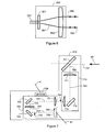
- Figures 8a and 8b show an unrotated cube-comer retroreflector.
- the roll angle is zero
- the yaw angle is zero
- the pitch angle is zero
- the x direction shown in Figures 8a and 8b is opposite the direction of the laser beam that is sent into the retroreflector.
- the three perpendicular reflecting surfaces of the cube-comer retroreflector form three lines of intersection.
- the x - y plane contains the x axis and one of the lines of intersection.
- the x - y plane also contains the y axis, which is perpendicular to the x axis and passes through the vertex of the cube corner.
- the dashed line in Figure 8a is parallel to they axis and has been included for clarity.
- the y and z axes lie in the plane of the paper, while the x axis points out of the paper.
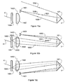
- Figures 11a and 11b show the effect of rotating the retroreflector about the x " axis by the roll angle R, which is 40 degrees in this example. Note that in Figure 11b , the x axis (direction opposite that of the laser beam) still points straight out of the paper.
- the roll, yaw, and pitch angles are found from a measurement of the three lines of intersection by the orientation camera 210.
- the camera detects the three lines of intersection of cube-comer retroreflector 107.
- the vertex of cube-comer retroreflector 107 which is defined as the common point of the three reflecting surfaces, remains centered on the photosensitive array 725 of Figure 7 .
- the electrical signals from photosensitive array 725 may be sent to a local digital-signal processing chip or sent over electrical wires 41 to electronics box 140 of Figure 1 . These electrical components determine the slopes of the three lines of intersection.
- the y and z axes on the surface of photosensitive array 725 point in the horizontal and vertical directions, respectively.
- the visibility of the lines on photosensitive array 725 of Figure 7 may be improved by increasing the thickness of the lines of intersection of retroreflector 107 or by coating the lines with a non-reflective material. Thicker lines of intersection on retroreflector 107 will cause the images of the lines seen on the photosensitive array to have higher contrast. However, thicker lines of intersection on retroreflector 107 will not usually result in thicker image lines on photosensitive array 725. Usually, the thickness of the lines as seen on photosensitive array 725 is determined by the effects of diffraction of the laser light that passes through the clear aperture of laser tracker 100.
- the deleterious effects of diffraction are also smaller when the retroreflector 107 is moved closer to the laser tracker 100. Fortunately, for the system considered here, the smearing effects of diffraction are symmetrical about the lines of intersection, so there is no bias in measuring the slopes of the lines.
- FIG 12 The appearance of the lines on the image of photosensitive array is shown in Figure 12 .
- the lines on this image that pass through vertex V appear on both sides of the vertex.
- Figure 11b shows that the lines of intersection of the physical cube-comer retroreflector appear on only one side of the vertex. This difference is the result of the symmetry in the paths that light can take when the laser beam is centered on vertex V. For example, if a pencil of light reflects off mirror 1, then mirror 2, then mirror 3 of the cube corner, then another pencil of light can reflect off mirror 3, then mirror 2, then mirror 1. If, instead of striking a mirror, the pencil of light strikes a line of intersection, then the light will not reflect back to the tracker and a dark spot will appear on the image of photosensitive array 725.
- Another simple but effective method is to temporarily turn off or reduce the power of the laser beam 153 emitted by laser tracker 100 and, at the same time, to increase the exposure time of photosensitive array 725. Under these conditions, the photosensitive array will ordinarily be able to make out the features of housing 109 and hence obtain information on the orientation of retroreflector 107.
- a third method for assigning the line segments to the corresponding lines of intersection is described in a second embodiment that is discussed later.
- the method for determining the pitch, roll, and yaw angles as described above provides has two main advantages. First, an essentially constant-magnification camera maintains the accuracy of the measurement for a probe located either near the tracker or far from it. Second, elimination of spurious diffraction effects improves accuracy, which may otherwise change the angles of the lines or dramatically change the appearance of the lines, especially at large distances.
- Figure 1 shows that housing 109 can be pivoted about axis 182 mounted on adjustable stage 181 and then locked in place.
- This allows cube-comer retroreflector 107 to be oriented in any desired direction.
- This flexibility in the orientation of retroreflector 107 is desirable because it allows probe tip 171 to be placed in slots, holes, and so forth at any given angle.
- shaft 182 is aligned with the vertex of retroreflector 107 to simplify calculations to determine the location of probe tip 171. If the locking mechanism allows a limited number of angular adjustments, each known to a sufficient angular accuracy (perhaps a few arc seconds), then measurement may resume as soon as the lock down is complete.
- an alternative approach involves adjusting housing 109 to any given orientation and performing a simple compensation routine to determine the angle between retroreflector 107 and probe shaft 170.
- a compensation routine might include measuring the location of a reference point with a spherically mounted retroreflector target and then measuring the same location with probe assembly 180 tilted to cover a range of pitch, yaw, and roll angles.
- the cube-comer retroreflector 107 which is made of three reflecting mirrors, with a cube-comer retroreflector prism formed of solid glass.
- Each type of retroreflector has advantages.
- the cube-comer retroreflector that uses mirrors also known as a hollow-core cube-comer retroreflector
- the solid glass cube-comer retroreflector has a wider field of view and is usually less expensive. Equations (2), (3), and (4) can be readily modified to account for a solid-glass, rather than a hollow-core, cube-comer retroreflector.
- the locator-camera block 230 of Figure 2 allows laser tracker 100 to quickly determine the approximate location of multiple retroreflectors within a wide field of view.
- the locator camera is shown in greater detail in Figures 14a and 14b .
- locator-camera block 230 is placed to one side of rigid structure 190 and has an aperture at 231, which might be considered the "top" side of rigid structure 190.
- rigid structure 190 is rotated about the center of shaft 270
- locator-camera block 230 faces the retroreflectors in the region of interest.
- Locator-camera block 230 then emits cone of light 1320 as shown in Figure 13 . This light reflects off retroreflectors 107, 1311, 1312, and 1313 shown in Figure 13 .
- retroreflector 107 represents a target of interest and retroreflectors 1311, 1312, and 1313 represent a number of other targets.
- the corresponding reflected light bundles 1357, 1351, 1352, and 1353 enter rigid structure 190.
- the light entering locator-camera block 230 falls onto a photosensitive array 1404 in Figure 14b , and the pattern is analyzed to determine the approximate location of the targets in the region of interest.
- Figures 14a and 14b depict an example locator-camera arrangement.
- a plurality of identical light sources 1401 is provided in a ring surrounding a lens 1402.
- the individual light sources emit overlapping cones of essentially incoherent light 1440 that collectively constitute the cone of light 1320 in Figure 13 .
- Each of the retroreflectors 107, 1311 - 1313 reflects some of the light from the cone of light 1320 back to the locator-camera block 230 as the bundles of light 1351 - 1353 or 1357.
- the bundle of light 1357 is shown in Figure 14b .
- Lens 1402 focuses the bundle 1357 down to a spot on the surface of photosensitive array 1404.
- the photosensitive array 1404 is separated from the front principal plane, 1403, of lens 1402 by the focal length f of the lens.
- Electrical wires 41 provide power from electronics box 140 to light emitters 1401 and photosensitive array 1404. Electrical wires 41 also transmit the pixel data from photosensitive array 1404 to electronics box 140 for analysis. Electronics box 41 analyzes the pattern of light on photosensitive array 1404 to determine the location of central point 1452 on photosensitive array 1404. Electronics box 140 also performs this analysis of the pattern formed by the other bundles of light returned by the retroreflectors. In other words, reflected light bundles 1357, 1351, 1352, and 1353 are focused by lens 1402 into patterns on photosensitive array 1404. Electronics box analyzes these patterns to determine the central point of each pattern. From the location of the central points, the approximate angular direction to each of the retroreflectors can be determined.
- the retroreflector of interest is retroreflector 107.
- motors 80 and 81 are activated to turn rigid structure 190 until laser beam 153 points in the approximate direction of retroreflector 107.
- the tracker then begins a search pattern, in which the direction of laser beam 153 is changed in a systematic fashion. For example, the laser beam might be steered along a spiral pattern.
- position detector 341 of Figure 3 senses the reflected light. The signals from position detector 341 provide enough information to enable motors 80 and 81 to point rigid structure 190 directly to the center of retroreflector 107.
- Figure 15a shows rays of light emitted by light emitter 1401 located above lens 1402.
- Ray of light 1520 travels to vertex V of retroreflector 107.
- Reflected light 1521 is sent directly back to light emitter 1401. It does not enter lens 1402 or appear as a spot of light on photosensitive array 1404.
- Ray of light 1530 is sent to the bottom of retroreflector 107 and emerges as reflected light 1532. It also misses lens 1402 and photosensitive array 1404.
- Figure 15b shows additional rays of light from light emitter 1401 located above lens 1402.
- Light emitter 1401 sends ray of light 1540 to a location above vertex V on retroreflector 107. This ray emerges as reflected ray 1541, which passes near the top of lens 1402, is bent into ray 1542, and arrives at photosensitive array 1404 near central point 1563.
- Light emitter 1401 sends ray of light 1550 to the top of retroreflector 107. This ray emerges as reflected ray 1552, which travels to lens 1402, is bent into ray 1553, and arrives at photosensitive array 1404 near central point 1563.
- rays 1541 and 1552 become nearly parallel, and the spot of light about point 1563 gets smaller and smaller.
- Figure 15c shows rays of light from light emitter 1401 located below lens 1402.
- the rays of light in the bottom diagram are mirror images of the rays in the middle diagram. If N is the number of pixels in photosensitive array 1404, W is the width of photosensitive array 1404, D is the diameter of lens 1402, and h is the distance from the edge of lens 1402 to light emitters 1401, the number of pixels between central points 1563 and 1593 will, in most cases, be less than [2N(D + h )/ L ]arctan( W /2 f ).
- the number of pixels between central points 1563 and 1593 will be less than six. Since light emitters 1401 are arranged in a circle, the image will be symmetrical, somewhat blurry, and about six pixels across. For retroreflectors further than 3 meters away, as most will be, the pattern of dots will be smaller. Electrical signals are sent from photosensitive array 1404 through electrical wire 41 to electronics box 140. Electronics box 140 analyzes the intensity of light in the pixels to obtain the best estimate of the center of the pattern produced by each retroreflector.
- Figure 16 shows a configuration of a fiber launch laser tracker 1600 for providing advantageous routing of optical fibers.
- optical fibers are preferably routed close to the two mechanical axes 1670 and 1671.
- the routing of the optical fibers in the system of Figure 16 has many advantages. For example, a large angular field of view of the tracker can be obtained. Also, bending or kinking of the optical fibers is prevented, thereby preserving measurement accuracy.
- Laser beam 1653 which is launched from rigid plate 1690, travels to retroreflector 107 as shown in Figure land returns as laser beam 1663.
- Laser light from optical fiber 1611 is collimated by lens 1613, reflected by mirror 1615, and transmitted through beam splitter 1614.
- Laser light from optical fiber 1612 is collimated by lens 1612 and reflected off beamsplitter 1614. Any number of laser beams can be combined into a common path to form outgoing laser beam 1653. Returning laser light may pass through a number of elements as previously discussed and omitted in Figure 16 for clarity. For example, beam splitters for the position detector and the orientation camera may be employed in accordance with the specific application. The returning laser light may reflect offbeam splitter 1614 and pass through lens 1612 to be coupled into optical fiber 1610. Alternatively, the laser light may pass into another device located on rigid plate 1690 for processing as previously discussed, for example, with reference to the absolute distance meter and the interferometer. Similarly, the returning laser light may reflect off mirror 1615 and couple back into optical fiber 1611. Alternatively, this laser light may travel to another device on rigid plate 1690 for processing.
- the direction of laser beam 1653 is determined by the orientation of rigid plate 1690, which in turn is determined by the angle of rotation of the zenith mechanical axis 1671 and the azimuth mechanical axis 1670.
- the zenith motor 1681 rotates the zenith axis 1671
- the azimuth motor 1680 rotates the azimuth axis 1670.
- Zenith angular encoder 1691 and the azimuth angular encoder 1690 measure the zenith and azimuth angles.
- Bearings 1681 and 1680 are also attached to the zenith and azimuth axes.
- zenith bearings 1621, zenith angular encoder 1691, and zenith motor 1681 are attached to the azimuth structural frame (not shown).
- the azimuth structural frame turns with the azimuth axis. Consequently, the zenith axis rotates within the azimuth structural frame.
- the outside of azimuth bearings 1620, azimuth angular encoder 1690, and azimuth motor 1680 are attached to stationary structural frame (not shown).
- the stationary structural frame is stationary with respect to the surroundings to which the tracker is mounted. Consequently, the azimuth axis rotates within the stationary structural frame.
- Optical fibers 1610 and 1611 are incorporated into optical fiber assembly 1605.
- Optical fiber assembly 1605 passes through zenith axis 1671 and azimuth axis 1670.
- Lasers within optoelectronic module 1606 (which, like the azimuth motor 1680, is stationary) inject laser light into optical fibers 1610 and 1611.
- Optoelectronic module 1606 may also contain optical detectors and electronics to determine the distance to retroreflector 107 or to a diffuse surface under investigation.
- the optical fiber assembly 1605 travels from optoelectronic module 1606 to the underside of azimuth axis 1670. It is attached to the stationary structural frame near point A shown in Figure 16 . At point A, the fiber is stationary with respect to the rotating azimuth axis.
- optical fiber assembly 1605 is attached to the azimuth structural frame near point B, which rotates along with azimuth axis 1670. Since one end of the fiber is fixed and the other end of the fiber is rotating with respect to the rotation of the azimuth axis, the optical fiber will experience a torsional twist. In most cases, a gentle twist of this sort will not degrade measurement accuracy.
- Optical fiber assembly 1605 is routed to the zenith axis, where it is attached to the azimuth structural frame near point C. At point C, the fiber is stationary with respect to the rotating zenith axis. At the other end of the zenith axis, fiber assembly 1605 is attached near point D, which rotates along with the zenith axis 1671.
- Optical fiber assembly 1605 is routed through the two mechanical axes.
- the fiber assembly is stationary at one end of each axis. At the other end, the fiber assembly rotates along with the axis. This produces a torsional twist, which is acceptable in most situations.
- a slightly different method of routing optical fiber assembly 1605 near the two mechanical axes may be preferable in some cases.
- the optical fibers are placed in coils to the outside of the mechanical axes, with the end of the optical fiber attached at one end to a point that is stationary relative to the mechanical axis and at the other end attached to a point that moves with the mechanical axis.
- the diameter of the coils will change slightly as the axis is rotated. In most cases, this small change in the radius of the coiled fiber assembly will not adversely affect measurement accuracy.
- the second embodiment of the invention is generally similar to that shown in Figure 1 except for the probe assembly 180 is replaced by probe assembly 1780, as shown in Figure 17 .
- Probe assembly 1780 contains a single small retroreflector 1708 to the side of retroreflector 107. Retroreflector 1708 is approximately aligned with the first line of intersection.
- the photosensitive array 725 of Figure 7 displays a pattern similar to that of Figure 12 , with the details of the pattern dependant on the pitch, yaw, and roll angles of retroreflector 107. As explained previously, at the start of the measurement, it is not possible to tell which line segments correspond to each of the three lines of intersection.
- the tracker performs a search in which it directs laser beam 153 in succession to each of the six possible locations of retroreflector 1708.
- a flash of light on position detector 341 of Figure 3 indicates that the first line of intersection has been identified.
- two thin wires 1711 and 1712 have been stretched across the top of retroreflector 107. Additional thin wires or alternative shapes may also be used. These wires provide redundant information for determining the pitch, yaw, and roll angles for those cases in which accuracy is more important than measurement speed.
- Probe assemblies 180 and 1780 can be used in either a scanning mode or a trigger mode.
- probe tip 171 shown in Figures 1 and 17
- data is continually collected at a high rate.
- probe 180 or 1780 is moved successively to the points of interest.
- the operator triggers the measurement by performing an action such as pressing a button or issuing a voice command.
- Either target object 185 in the first preferred embodiment or target object 1785 in the second preferred embodiment can be detached from adjustable stage 181 and probe shaft 170, then attached to the end effector of a robot arm.
- the target object can be attached to a machine tool such as a drilling or milling machine.
- the tracker sends a laser beam to the target object to determine the six degrees of freedom of the drill or mill.
- the information provided by the tracker on the six degrees of freedom of target object 185 or 1785 can be used in a control loop to precisely direct the machine tool or robot end effector to the desired locations. If the tracker measures the six degrees of freedom fast enough, real-time control of machine tools and robots is possible.
- the third embodiment of the invention provides a laser tracker 1800 as shown in Figure 18 that uses a steering reflector 1804 within gimbal mount 95 to direct laser beam 1853 to retroreflector 107.
- Laser 1802 emits laser light that is sent to retroreflector 107.
- Optical block 1806 contains beam expander 220 and any other optical beam-conditioning elements that may be required.
- Laser light returning from retroreflector 107 is sent to distance-measuring device 1814, which may be either an absolute-distance meter or an incremental-distance meter. Part of the returning laser light is also reflected off beam splitter 1809 to position detector 341.
- the beam splitter 701 reflects a portion of laser beam 54 into orientation-camera subsystem 1810.
- Orientation camera subsystem 1810 comprises afocal lens block 710 and relay/array block 720, also shown in Figure 7 .
- the optical elements within blocks 1806 and 1810 of Figure 18 are substantially equivalent to the optical elements within blocks 220 and 210 of Figures 6 and 7 .
- an orientation camera comprising elements 701 and 1810 is embedded within laser tracker 1800. This orientation camera is equivalent to the orientation camera 210 of Figure 2 and can therefore be used to measure the six degrees of freedom of target object 185.
Priority Applications (1)
| Application Number | Priority Date | Filing Date | Title |
|---|---|---|---|
| EP10012367.8A EP2275775B1 (fr) | 2002-01-16 | 2002-01-16 | Dispositif de mesure de coordonnées à base de laser et procédé à base de laser pour mesurer les coordonnées |
Applications Claiming Priority (3)
| Application Number | Priority Date | Filing Date | Title |
|---|---|---|---|
| PCT/US2002/001346 WO2003062744A1 (fr) | 2002-01-16 | 2002-01-16 | Dispositif et procede de mesure de coordonnees par laser |
| EP10012367.8A EP2275775B1 (fr) | 2002-01-16 | 2002-01-16 | Dispositif de mesure de coordonnées à base de laser et procédé à base de laser pour mesurer les coordonnées |
| EP02720805A EP1466136B1 (fr) | 2002-01-16 | 2002-01-16 | Dispositif et procede de mesure de coordonnees par laser |
Related Parent Applications (2)
| Application Number | Title | Priority Date | Filing Date |
|---|---|---|---|
| EP02720805.7 Division | 2002-01-16 | ||
| EP02720805A Division EP1466136B1 (fr) | 2002-01-16 | 2002-01-16 | Dispositif et procede de mesure de coordonnees par laser |
Publications (3)
| Publication Number | Publication Date |
|---|---|
| EP2275775A2 true EP2275775A2 (fr) | 2011-01-19 |
| EP2275775A3 EP2275775A3 (fr) | 2013-09-18 |
| EP2275775B1 EP2275775B1 (fr) | 2015-09-23 |
Family
ID=27608964
Family Applications (2)
| Application Number | Title | Priority Date | Filing Date |
|---|---|---|---|
| EP10012367.8A Revoked EP2275775B1 (fr) | 2002-01-16 | 2002-01-16 | Dispositif de mesure de coordonnées à base de laser et procédé à base de laser pour mesurer les coordonnées |
| EP02720805A Expired - Lifetime EP1466136B1 (fr) | 2002-01-16 | 2002-01-16 | Dispositif et procede de mesure de coordonnees par laser |
Family Applications After (1)
| Application Number | Title | Priority Date | Filing Date |
|---|---|---|---|
| EP02720805A Expired - Lifetime EP1466136B1 (fr) | 2002-01-16 | 2002-01-16 | Dispositif et procede de mesure de coordonnees par laser |
Country Status (3)
| Country | Link |
|---|---|
| EP (2) | EP2275775B1 (fr) |
| AT (1) | ATE519092T1 (fr) |
| WO (1) | WO2003062744A1 (fr) |
Cited By (10)
| Publication number | Priority date | Publication date | Assignee | Title |
|---|---|---|---|---|
| JP2014514561A (ja) * | 2011-04-15 | 2014-06-19 | ファロ テクノロジーズ インコーポレーテッド | 光ファイバカプラで二種類の波長を結合させるレーザトラッカ |
| EP3015839A1 (fr) | 2014-10-31 | 2016-05-04 | Agisco S.r.l. | Système de pointage laser pour surveiller la stabilité de structures |
| CN106546172A (zh) * | 2016-10-20 | 2017-03-29 | 天津大学 | 基于非正交轴系激光全站仪的三维坐标测量方法 |
| CN108051822A (zh) * | 2017-12-22 | 2018-05-18 | 湖北汽车工业学院 | 一种探测器及探测方法 |
| US10119805B2 (en) | 2011-04-15 | 2018-11-06 | Faro Technologies, Inc. | Three-dimensional coordinate scanner and method of operation |
| US10209059B2 (en) | 2010-04-21 | 2019-02-19 | Faro Technologies, Inc. | Method and apparatus for following an operator and locking onto a retroreflector with a laser tracker |
| US10267619B2 (en) | 2011-04-15 | 2019-04-23 | Faro Technologies, Inc. | Three-dimensional coordinate scanner and method of operation |
| US11493632B2 (en) | 2018-10-17 | 2022-11-08 | Trimble Jena Gmbh | Tracker of a surveying apparatus for tracking a target |
| US11493340B2 (en) | 2019-02-15 | 2022-11-08 | Trimble Jena Gmbh | Surveying instrument and method of calibrating a survey instrument |
| US11525677B2 (en) | 2018-10-17 | 2022-12-13 | Trimble Jena Gmbh | Surveying apparatus for surveying an object |
Families Citing this family (70)
| Publication number | Priority date | Publication date | Assignee | Title |
|---|---|---|---|---|
| EP1794620B1 (fr) | 2004-09-30 | 2014-01-01 | Faro Technologies Inc. | Appareil de mesure de distance absolue permettant de mesurer la distance a un retroreflecteur mobile |
| EP1659417A1 (fr) * | 2004-11-19 | 2006-05-24 | Leica Geosystems AG | Procédé pour la détermination de l'orientation d'un outil d'orientation |
| US8082120B2 (en) | 2005-03-11 | 2011-12-20 | Creaform Inc. | Hand-held self-referenced apparatus for three-dimensional scanning |
| EP1877726B1 (fr) * | 2005-03-11 | 2011-07-27 | Creaform Inc. | Systeme autoreference et appareil de lecture optique 3d |
| DE102005043912B4 (de) * | 2005-05-18 | 2011-08-18 | Steinbichler Optotechnik GmbH, 83115 | Verfahren zum Bestimmen der 3D-Koordinaten der Oberfläche eines Objekts |
| CN101371160B (zh) * | 2006-01-13 | 2012-10-03 | 莱卡地球系统公开股份有限公司 | 跟踪方法以及配有激光跟踪仪的测量系统 |
| AU2007204542B2 (en) * | 2006-01-13 | 2013-12-05 | Leica Geosystems Ag | Coordinate measurement instrument |
| ITRM20060651A1 (it) * | 2006-12-06 | 2008-06-07 | Enea Ente Nuove Tec | Metodo e dispositivo radar ottico tridimensionale utilizzante tre fasci rgb modulati da diodi laser, in particolare per applicazioni metrologiche e delle belle arti. |
| DE102008027976A1 (de) | 2008-06-12 | 2009-12-31 | Steinbichler Optotechnik Gmbh | Verfahren und Vorrichtung zur Ermittlung der Lage eines Sensors |
| US8284240B2 (en) | 2008-08-06 | 2012-10-09 | Creaform Inc. | System for adaptive three-dimensional scanning of surface characteristics |
| US9482755B2 (en) | 2008-11-17 | 2016-11-01 | Faro Technologies, Inc. | Measurement system having air temperature compensation between a target and a laser tracker |
| JP2012509464A (ja) | 2008-11-17 | 2012-04-19 | ファロ テクノロジーズ インコーポレーテッド | 六自由度計測装置及び方法 |
| US8659749B2 (en) | 2009-08-07 | 2014-02-25 | Faro Technologies, Inc. | Absolute distance meter with optical switch |
| DE102009040837A1 (de) * | 2009-09-10 | 2011-03-17 | Carl Zeiss Ag | Vorrichtungen und Verfahren zur Positionsbestimmung und Oberflächenvermessung |
| US8497981B2 (en) | 2009-09-15 | 2013-07-30 | Qualcomm Incorporated | Small form-factor size sensor |
| US8396685B2 (en) | 2009-09-15 | 2013-03-12 | Qualcomm Incorporated | Small form-factor distance sensor |
| US20110069322A1 (en) * | 2009-09-21 | 2011-03-24 | Faro Technologies, Inc. | Laser pointing mechanism |
| CN102713514B (zh) | 2010-01-18 | 2015-04-22 | 法罗技术股份有限公司 | 用于跟踪隐藏点的回射器探头适配器 |
| CN102834694B (zh) * | 2010-02-11 | 2014-11-12 | 特林布尔公司 | 双发射机跟踪器 |
| IT1399420B1 (it) * | 2010-04-08 | 2013-04-16 | Ocn S P A | "metodo di rilevamento della estremita' finale di un avvolgimento" |
| CN101819270A (zh) * | 2010-04-19 | 2010-09-01 | 天津宝成新宇电子科技有限公司 | 基于激光扫描光纤耦合系统的激光雷达发射装置 |
| US9400170B2 (en) | 2010-04-21 | 2016-07-26 | Faro Technologies, Inc. | Automatic measurement of dimensional data within an acceptance region by a laser tracker |
| US8422034B2 (en) | 2010-04-21 | 2013-04-16 | Faro Technologies, Inc. | Method and apparatus for using gestures to control a laser tracker |
| US8619265B2 (en) | 2011-03-14 | 2013-12-31 | Faro Technologies, Inc. | Automatic measurement of dimensional data with a laser tracker |
| US9377885B2 (en) | 2010-04-21 | 2016-06-28 | Faro Technologies, Inc. | Method and apparatus for locking onto a retroreflector with a laser tracker |
| US8724119B2 (en) | 2010-04-21 | 2014-05-13 | Faro Technologies, Inc. | Method for using a handheld appliance to select, lock onto, and track a retroreflector with a laser tracker |
| US8537371B2 (en) | 2010-04-21 | 2013-09-17 | Faro Technologies, Inc. | Method and apparatus for using gestures to control a laser tracker |
| US8416396B2 (en) | 2010-07-18 | 2013-04-09 | David H. Parker | Methods and apparatus for optical amplitude modulated wavefront shaping |
| DE112011102995B4 (de) | 2010-09-08 | 2016-05-19 | Faro Technologies Inc. | Laserscanner oder Lasernachführungsgerät mit einem Projektor |
| US8902408B2 (en) | 2011-02-14 | 2014-12-02 | Faro Technologies Inc. | Laser tracker used with six degree-of-freedom probe having separable spherical retroreflector |
| DE112012001082B4 (de) | 2011-03-03 | 2015-12-03 | Faro Technologies Inc. | Verfahren zum Messen von Zielen |
| FR2973107B1 (fr) * | 2011-03-21 | 2013-04-12 | Tiama | Dispositif de controle dimensionnel de recipients munis d'un buvant |
| US9164173B2 (en) | 2011-04-15 | 2015-10-20 | Faro Technologies, Inc. | Laser tracker that uses a fiber-optic coupler and an achromatic launch to align and collimate two wavelengths of light |
| US9686532B2 (en) | 2011-04-15 | 2017-06-20 | Faro Technologies, Inc. | System and method of acquiring three-dimensional coordinates using multiple coordinate measurement devices |
| USD688577S1 (en) | 2012-02-21 | 2013-08-27 | Faro Technologies, Inc. | Laser tracker |
| US9222771B2 (en) | 2011-10-17 | 2015-12-29 | Kla-Tencor Corp. | Acquisition of information for a construction site |
| EP2589982A1 (fr) | 2011-11-03 | 2013-05-08 | Leica Geosystems AG | Diode laser comme source de rayonnement laser d'interféromètre dans un appareil de suivi laser |
| CN104094081A (zh) | 2012-01-27 | 2014-10-08 | 法罗技术股份有限公司 | 利用条形码识别的检查方法 |
| EP2620746A1 (fr) * | 2012-01-30 | 2013-07-31 | Hexagon Technology Center GmbH | Dispositif d'arpentage doté d'une fonctionnalité de balayage et d'un mode de mesure à point unique |
| EP2634594A1 (fr) | 2012-03-01 | 2013-09-04 | Leica Geosystems AG | Procédé de détermination d'une modification d'éloignement par interférométrie |
| EP2645125B1 (fr) * | 2012-03-27 | 2017-05-10 | Sick AG | Laser scanner et procédé destiné à la détection d'objets dans une zone de surveillance |
| US9864184B2 (en) | 2012-10-30 | 2018-01-09 | California Institute Of Technology | Embedded pupil function recovery for fourier ptychographic imaging devices |
| US10652444B2 (en) | 2012-10-30 | 2020-05-12 | California Institute Of Technology | Multiplexed Fourier ptychography imaging systems and methods |
| US10679763B2 (en) | 2012-10-30 | 2020-06-09 | California Institute Of Technology | Fourier ptychographic imaging systems, devices, and methods |
| EP2738570A1 (fr) * | 2012-11-29 | 2014-06-04 | BAE Systems PLC | Commande de poursuite laser |
| EP3028088B1 (fr) | 2013-07-31 | 2022-01-19 | California Institute of Technology | Imagerie ptychographique de fourier à balayage à ouverture |
| JP6221197B2 (ja) * | 2013-08-06 | 2017-11-01 | 株式会社東京精密 | レーザトラッカ |
| CN110082900B (zh) | 2013-08-22 | 2022-05-13 | 加州理工学院 | 可变照明傅立叶重叠关联成像设备、系统以及方法 |
| US11468557B2 (en) | 2014-03-13 | 2022-10-11 | California Institute Of Technology | Free orientation fourier camera |
| US10162161B2 (en) | 2014-05-13 | 2018-12-25 | California Institute Of Technology | Ptychography imaging systems and methods with convex relaxation |
| US9395174B2 (en) | 2014-06-27 | 2016-07-19 | Faro Technologies, Inc. | Determining retroreflector orientation by optimizing spatial fit |
| EP2980526B1 (fr) | 2014-07-30 | 2019-01-16 | Leica Geosystems AG | Appareil et méthode de mesure de coordonnées |
| GB2530053A (en) * | 2014-09-10 | 2016-03-16 | Capaltec Ltd | Measuring device |
| EP3032277B1 (fr) | 2014-12-12 | 2021-04-07 | Leica Geosystems AG | Appareil de suivi laser |
| CN107111118B (zh) | 2014-12-22 | 2019-12-10 | 加州理工学院 | 用于厚样本的epi照明傅立叶重叠关联成像 |
| AU2016209275A1 (en) | 2015-01-21 | 2017-06-29 | California Institute Of Technology | Fourier ptychographic tomography |
| CN107003245B (zh) | 2015-01-26 | 2018-11-06 | 加州理工学院 | 阵列级傅立叶重叠关联成像 |
| JP2018509622A (ja) | 2015-03-13 | 2018-04-05 | カリフォルニア インスティチュート オブ テクノロジー | フーリエタイコグラフィ手法を用いるインコヒーレント撮像システムにおける収差補正 |
| US9993149B2 (en) | 2015-03-25 | 2018-06-12 | California Institute Of Technology | Fourier ptychographic retinal imaging methods and systems |
| WO2016187591A1 (fr) * | 2015-05-21 | 2016-11-24 | California Institute Of Technology | Systèmes et procédés d'imagerie ptychographique de fourier à laser |
| EP3208636B1 (fr) | 2016-02-19 | 2018-01-24 | Sick Ag | Capteur optoélectronique et procédé destiné à la saisie d'objets |
| EP3220163B1 (fr) | 2016-03-15 | 2021-07-07 | Leica Geosystems AG | Appareil de suivi laser à deux fonctionnalités de mesure |
| TWI595252B (zh) * | 2016-05-10 | 2017-08-11 | 財團法人工業技術研究院 | 測距裝置及其測距方法 |
| US11092795B2 (en) | 2016-06-10 | 2021-08-17 | California Institute Of Technology | Systems and methods for coded-aperture-based correction of aberration obtained from Fourier ptychography |
| US10568507B2 (en) | 2016-06-10 | 2020-02-25 | California Institute Of Technology | Pupil ptychography methods and systems |
| CN107289903B (zh) * | 2017-06-16 | 2023-07-14 | 郑州市市政工程总公司 | 直线桥梁悬臂法施工线形连续测量监测系统及监测方法 |
| WO2019090149A1 (fr) | 2017-11-03 | 2019-05-09 | California Institute Of Technology | Procédés et systèmes d'acquisition et de restauration parallèles d'images numériques |
| CN112304214B (zh) * | 2019-08-01 | 2022-10-11 | 上海飞机制造有限公司 | 基于摄影测量的工装检测方法和工装检测系统 |
| CN112945109B (zh) * | 2021-01-26 | 2023-03-31 | 西安交通大学 | 基于水平位移台的激光位移计阵列系统参数标定方法 |
| CN117386957B (zh) * | 2023-12-11 | 2024-02-13 | 成都匠泰建筑工程设计有限公司 | 一种生态园林景观规划施工用测量装置 |
Citations (20)
| Publication number | Priority date | Publication date | Assignee | Title |
|---|---|---|---|---|
| US4020340A (en) | 1971-03-22 | 1977-04-26 | Gte Sylvania Incorporated | Precision automatic tracking system |
| US4025193A (en) | 1974-02-11 | 1977-05-24 | The Boeing Company | Apparatus suitable for use in orienting aircraft in-flight for refueling or other purposes |
| US4386848A (en) | 1980-08-11 | 1983-06-07 | Martin Marietta Corporation | Optical target tracking and designating system |
| DE3205362A1 (de) | 1982-02-15 | 1983-08-25 | Pfeifer, Tilo, Prof. Dr.-Ing. | Raeumliches wegmesssystem |
| US4436417A (en) | 1982-04-14 | 1984-03-13 | Itek Corporation | Beam director for optical ranging system |
| US4457625A (en) | 1981-07-13 | 1984-07-03 | Itek Corporation | Self calibrating contour measuring system using fringe counting interferometers |
| US4459022A (en) | 1980-10-16 | 1984-07-10 | United Technologies Corporation | Fiber optic angular sensor |
| US4714339A (en) | 1986-02-28 | 1987-12-22 | The United States Of America As Represented By The Secretary Of Commerce | Three and five axis laser tracking systems |
| US4721385A (en) | 1985-02-11 | 1988-01-26 | Raytheon Company | FM-CW laser radar system |
| US4790651A (en) | 1987-09-30 | 1988-12-13 | Chesapeake Laser Systems, Inc. | Tracking laser interferometer |
| US5059789A (en) | 1990-10-22 | 1991-10-22 | International Business Machines Corp. | Optical position and orientation sensor |
| US5095472A (en) | 1989-06-02 | 1992-03-10 | Hitachi Cable Limited | Focusing error detecting system for optical head |
| US5198874A (en) | 1991-04-22 | 1993-03-30 | Sheffield Measurement Division | Coordinate measuring machine with laser interferometer and fiber optic laser delivery system |
| US5200838A (en) | 1988-05-27 | 1993-04-06 | The University Of Connecticut | Lateral effect imaging system |
| US5267014A (en) | 1992-04-21 | 1993-11-30 | Bodenseewerk Geratetechnik Gmbh | Position and orientation measurement device |
| US5367373A (en) | 1992-11-19 | 1994-11-22 | Board Of Regents, The University Of Texas System | Noncontact position measurement systems using optical sensors |
| US5402230A (en) | 1991-12-16 | 1995-03-28 | Tsinghua University | Heterodyne interferometric optical fiber displacement sensor for measuring displacement of an object |
| US5508804A (en) | 1993-03-27 | 1996-04-16 | Deutsche Forschungsanstatt Fur Luft- Und Raumfahrt E.V. | Laser interferometer strain sensor with adjustable feedback amplification in the form of a saw-tooth pattern |
| US5557406A (en) | 1995-02-28 | 1996-09-17 | The Texas A&M University System | Signal conditioning unit for fiber optic sensors |
| US5973788A (en) | 1995-10-12 | 1999-10-26 | Metronor Asa | System for point-by-point measuring of spatial coordinates |
Family Cites Families (4)
| Publication number | Priority date | Publication date | Assignee | Title |
|---|---|---|---|---|
| JPS60237307A (ja) | 1984-05-11 | 1985-11-26 | Yokogawa Hewlett Packard Ltd | レ−ザ測長器 |
| CH676041A5 (en) | 1988-07-22 | 1990-11-30 | Wild Leitz Ag | Surveying unit with theodolite and range finder - determines fine coordinates from coarsely determined target points and has light pulse transmitter and receiver |
| GB2285550B (en) * | 1994-01-05 | 1997-09-17 | Creo Products Inc | Optical coordinate measuring system for large objects |
| DE59901809D1 (de) | 1999-08-31 | 2002-07-25 | Leica Geosystems Ag | Tachymeter-Fernrohr |
-
2002
- 2002-01-16 WO PCT/US2002/001346 patent/WO2003062744A1/fr not_active Application Discontinuation
- 2002-01-16 AT AT02720805T patent/ATE519092T1/de not_active IP Right Cessation
- 2002-01-16 EP EP10012367.8A patent/EP2275775B1/fr not_active Revoked
- 2002-01-16 EP EP02720805A patent/EP1466136B1/fr not_active Expired - Lifetime
Patent Citations (22)
| Publication number | Priority date | Publication date | Assignee | Title |
|---|---|---|---|---|
| US4020340A (en) | 1971-03-22 | 1977-04-26 | Gte Sylvania Incorporated | Precision automatic tracking system |
| US4025193A (en) | 1974-02-11 | 1977-05-24 | The Boeing Company | Apparatus suitable for use in orienting aircraft in-flight for refueling or other purposes |
| US4386848A (en) | 1980-08-11 | 1983-06-07 | Martin Marietta Corporation | Optical target tracking and designating system |
| US4459022A (en) | 1980-10-16 | 1984-07-10 | United Technologies Corporation | Fiber optic angular sensor |
| US4457625A (en) | 1981-07-13 | 1984-07-03 | Itek Corporation | Self calibrating contour measuring system using fringe counting interferometers |
| DE3205362A1 (de) | 1982-02-15 | 1983-08-25 | Pfeifer, Tilo, Prof. Dr.-Ing. | Raeumliches wegmesssystem |
| US4436417A (en) | 1982-04-14 | 1984-03-13 | Itek Corporation | Beam director for optical ranging system |
| US4721385A (en) | 1985-02-11 | 1988-01-26 | Raytheon Company | FM-CW laser radar system |
| US4714339A (en) | 1986-02-28 | 1987-12-22 | The United States Of America As Represented By The Secretary Of Commerce | Three and five axis laser tracking systems |
| US4714339B1 (en) | 1986-02-28 | 1997-03-18 | Us Army | Three and five axis laser tracking systems |
| US4714339B2 (en) | 1986-02-28 | 2000-05-23 | Us Commerce | Three and five axis laser tracking systems |
| US4790651A (en) | 1987-09-30 | 1988-12-13 | Chesapeake Laser Systems, Inc. | Tracking laser interferometer |
| US5200838A (en) | 1988-05-27 | 1993-04-06 | The University Of Connecticut | Lateral effect imaging system |
| US5095472A (en) | 1989-06-02 | 1992-03-10 | Hitachi Cable Limited | Focusing error detecting system for optical head |
| US5059789A (en) | 1990-10-22 | 1991-10-22 | International Business Machines Corp. | Optical position and orientation sensor |
| US5198874A (en) | 1991-04-22 | 1993-03-30 | Sheffield Measurement Division | Coordinate measuring machine with laser interferometer and fiber optic laser delivery system |
| US5402230A (en) | 1991-12-16 | 1995-03-28 | Tsinghua University | Heterodyne interferometric optical fiber displacement sensor for measuring displacement of an object |
| US5267014A (en) | 1992-04-21 | 1993-11-30 | Bodenseewerk Geratetechnik Gmbh | Position and orientation measurement device |
| US5367373A (en) | 1992-11-19 | 1994-11-22 | Board Of Regents, The University Of Texas System | Noncontact position measurement systems using optical sensors |
| US5508804A (en) | 1993-03-27 | 1996-04-16 | Deutsche Forschungsanstatt Fur Luft- Und Raumfahrt E.V. | Laser interferometer strain sensor with adjustable feedback amplification in the form of a saw-tooth pattern |
| US5557406A (en) | 1995-02-28 | 1996-09-17 | The Texas A&M University System | Signal conditioning unit for fiber optic sensors |
| US5973788A (en) | 1995-10-12 | 1999-10-26 | Metronor Asa | System for point-by-point measuring of spatial coordinates |
Non-Patent Citations (7)
| Title |
|---|
| BERNARD; FENCIL, APPLIED OPTICS, 1966, pages 497 - 505 |
| LUCY ET AL., APPLIED OPTICS, 1966, pages 517 - 524 |
| NAKAMURA ET AL., REVIEW OF SCIENTIFIC INSTRUMENTS, 1994, pages 1006 - 1011 |
| SULLIVAN, SPIE, vol. 227, 1980, pages 148 - 161 |
| TAKATSUJI ET AL., MEASUREMENT SCIENCE & TECHNOLOGY, 1998, pages 1357 - 1359 |
| TAKATSUJI ET AL., MEASUREMENT SCIENCE & TECHNOLOGY, 1998, pages 38 - 41 |
| TAKATSUJI ET AL.: "Dimensional Metrology in the 21" Century", INTERNATIONAL DIMENSIONAL METROLOGY WORKSHOP SPONSORED BY OAK RIDGE METROLOGY CENTER, 10 May 1999 (1999-05-10) |
Cited By (17)
| Publication number | Priority date | Publication date | Assignee | Title |
|---|---|---|---|---|
| US10209059B2 (en) | 2010-04-21 | 2019-02-19 | Faro Technologies, Inc. | Method and apparatus for following an operator and locking onto a retroreflector with a laser tracker |
| US10480929B2 (en) | 2010-04-21 | 2019-11-19 | Faro Technologies, Inc. | Method and apparatus for following an operator and locking onto a retroreflector with a laser tracker |
| US10302413B2 (en) | 2011-04-15 | 2019-05-28 | Faro Technologies, Inc. | Six degree-of-freedom laser tracker that cooperates with a remote sensor |
| JP2014514561A (ja) * | 2011-04-15 | 2014-06-19 | ファロ テクノロジーズ インコーポレーテッド | 光ファイバカプラで二種類の波長を結合させるレーザトラッカ |
| US10119805B2 (en) | 2011-04-15 | 2018-11-06 | Faro Technologies, Inc. | Three-dimensional coordinate scanner and method of operation |
| US10578423B2 (en) | 2011-04-15 | 2020-03-03 | Faro Technologies, Inc. | Diagnosing multipath interference and eliminating multipath interference in 3D scanners using projection patterns |
| US10267619B2 (en) | 2011-04-15 | 2019-04-23 | Faro Technologies, Inc. | Three-dimensional coordinate scanner and method of operation |
| EP3015839A1 (fr) | 2014-10-31 | 2016-05-04 | Agisco S.r.l. | Système de pointage laser pour surveiller la stabilité de structures |
| CN106546172B (zh) * | 2016-10-20 | 2019-05-07 | 天津大学 | 基于非正交轴系激光全站仪的三维坐标测量方法 |
| CN106546172A (zh) * | 2016-10-20 | 2017-03-29 | 天津大学 | 基于非正交轴系激光全站仪的三维坐标测量方法 |
| CN108051822A (zh) * | 2017-12-22 | 2018-05-18 | 湖北汽车工业学院 | 一种探测器及探测方法 |
| CN108051822B (zh) * | 2017-12-22 | 2021-07-13 | 湖北汽车工业学院 | 一种探测器及探测方法 |
| US11493632B2 (en) | 2018-10-17 | 2022-11-08 | Trimble Jena Gmbh | Tracker of a surveying apparatus for tracking a target |
| US11525677B2 (en) | 2018-10-17 | 2022-12-13 | Trimble Jena Gmbh | Surveying apparatus for surveying an object |
| US11802966B2 (en) | 2018-10-17 | 2023-10-31 | Trimble Jena Gmbh | Tracker of a surveying apparatus for tracking a target |
| US11493340B2 (en) | 2019-02-15 | 2022-11-08 | Trimble Jena Gmbh | Surveying instrument and method of calibrating a survey instrument |
| US11566897B2 (en) | 2019-02-15 | 2023-01-31 | Trimble Jena Gmbh | Surveying instrument and method of calibrating a survey instrument |
Also Published As
| Publication number | Publication date |
|---|---|
| EP2275775B1 (fr) | 2015-09-23 |
| EP1466136B1 (fr) | 2011-08-03 |
| ATE519092T1 (de) | 2011-08-15 |
| WO2003062744A1 (fr) | 2003-07-31 |
| EP2275775A3 (fr) | 2013-09-18 |
| EP1466136A1 (fr) | 2004-10-13 |
Similar Documents
| Publication | Publication Date | Title |
|---|---|---|
| US9989350B2 (en) | Laser-based coordinate measuring device and laser-based method for measuring coordinates | |
| EP1466136B1 (fr) | Dispositif et procede de mesure de coordonnees par laser | |
| US11709240B2 (en) | Descan compensation in scanning LIDAR | |
| US9075025B2 (en) | Apparatus and method to compensate bearing runout in laser tracker | |
| US9482525B2 (en) | Apparatus to compensate bearing runout in a three-dimensional coordinate measuring system | |
| US7027162B2 (en) | System and method for three-dimensional measurement | |
| RU2292566C1 (ru) | Многофункциональная оптико-локационная система | |
| WO2012141810A1 (fr) | Appareil et procédé pour cible | |
| US6618132B1 (en) | Miniature laser tracker | |
| US20220123052A1 (en) | Techniques for fiber tip re-imaging in lidar systems | |
| RU2372628C1 (ru) | Многофункциональная оптико-локационная система |
Legal Events
| Date | Code | Title | Description |
|---|---|---|---|
| PUAI | Public reference made under article 153(3) epc to a published international application that has entered the european phase |
Free format text: ORIGINAL CODE: 0009012 |
|
| AC | Divisional application: reference to earlier application |
Ref document number: 1466136 Country of ref document: EP Kind code of ref document: P |
|
| AK | Designated contracting states |
Kind code of ref document: A2 Designated state(s): AT BE CH CY DE DK ES FI FR GB GR IE IT LI LU MC NL PT SE TR |
|
| PUAL | Search report despatched |
Free format text: ORIGINAL CODE: 0009013 |
|
| AK | Designated contracting states |
Kind code of ref document: A3 Designated state(s): AT BE CH CY DE DK ES FI FR GB GR IE IT LI LU MC NL PT SE TR |
|
| RIC1 | Information provided on ipc code assigned before grant |
Ipc: G01C 15/00 20060101ALI20130814BHEP Ipc: G01S 17/08 20060101ALI20130814BHEP Ipc: G01B 11/00 20060101AFI20130814BHEP Ipc: G01S 5/16 20060101ALI20130814BHEP Ipc: G01S 17/46 20060101ALI20130814BHEP |
|
| 17P | Request for examination filed |
Effective date: 20140318 |
|
| RBV | Designated contracting states (corrected) |
Designated state(s): AT BE CH CY DE DK ES FI FR GB GR IE IT LI LU MC NL PT SE TR |
|
| GRAP | Despatch of communication of intention to grant a patent |
Free format text: ORIGINAL CODE: EPIDOSNIGR1 |
|
| INTG | Intention to grant announced |
Effective date: 20150626 |
|
| RIN1 | Information on inventor provided before grant (corrected) |
Inventor name: ACKERSON, SCOTT D. Inventor name: BRIDGES, ROBERT E. Inventor name: BROWN, LAWRENCE B. Inventor name: WEST, JAMES K. |
|
| GRAS | Grant fee paid |
Free format text: ORIGINAL CODE: EPIDOSNIGR3 |
|
| GRAA | (expected) grant |
Free format text: ORIGINAL CODE: 0009210 |
|
| AC | Divisional application: reference to earlier application |
Ref document number: 1466136 Country of ref document: EP Kind code of ref document: P |
|
| AK | Designated contracting states |
Kind code of ref document: B1 Designated state(s): AT BE CH CY DE DK ES FI FR GB GR IE IT LI LU MC NL PT SE TR |
|
| REG | Reference to a national code |
Ref country code: GB Ref legal event code: FG4D |
|
| REG | Reference to a national code |
Ref country code: CH Ref legal event code: EP |
|
| REG | Reference to a national code |
Ref country code: AT Ref legal event code: REF Ref document number: 751483 Country of ref document: AT Kind code of ref document: T Effective date: 20151015 |
|
| REG | Reference to a national code |
Ref country code: IE Ref legal event code: FG4D |
|
| REG | Reference to a national code |
Ref country code: DE Ref legal event code: R096 Ref document number: 60247495 Country of ref document: DE |
|
| REG | Reference to a national code |
Ref country code: NL Ref legal event code: MP Effective date: 20150923 |
|
| PG25 | Lapsed in a contracting state [announced via postgrant information from national office to epo] |
Ref country code: GR Free format text: LAPSE BECAUSE OF FAILURE TO SUBMIT A TRANSLATION OF THE DESCRIPTION OR TO PAY THE FEE WITHIN THE PRESCRIBED TIME-LIMIT Effective date: 20151224 Ref country code: FI Free format text: LAPSE BECAUSE OF FAILURE TO SUBMIT A TRANSLATION OF THE DESCRIPTION OR TO PAY THE FEE WITHIN THE PRESCRIBED TIME-LIMIT Effective date: 20150923 |
|
| REG | Reference to a national code |
Ref country code: AT Ref legal event code: MK05 Ref document number: 751483 Country of ref document: AT Kind code of ref document: T Effective date: 20150923 |
|
| PG25 | Lapsed in a contracting state [announced via postgrant information from national office to epo] |
Ref country code: SE Free format text: LAPSE BECAUSE OF FAILURE TO SUBMIT A TRANSLATION OF THE DESCRIPTION OR TO PAY THE FEE WITHIN THE PRESCRIBED TIME-LIMIT Effective date: 20150923 |
|
| PG25 | Lapsed in a contracting state [announced via postgrant information from national office to epo] |
Ref country code: NL Free format text: LAPSE BECAUSE OF FAILURE TO SUBMIT A TRANSLATION OF THE DESCRIPTION OR TO PAY THE FEE WITHIN THE PRESCRIBED TIME-LIMIT Effective date: 20150923 |
|
| PG25 | Lapsed in a contracting state [announced via postgrant information from national office to epo] |
Ref country code: ES Free format text: LAPSE BECAUSE OF FAILURE TO SUBMIT A TRANSLATION OF THE DESCRIPTION OR TO PAY THE FEE WITHIN THE PRESCRIBED TIME-LIMIT Effective date: 20150923 Ref country code: IT Free format text: LAPSE BECAUSE OF FAILURE TO SUBMIT A TRANSLATION OF THE DESCRIPTION OR TO PAY THE FEE WITHIN THE PRESCRIBED TIME-LIMIT Effective date: 20150923 |
|
| PGFP | Annual fee paid to national office [announced via postgrant information from national office to epo] |
Ref country code: DE Payment date: 20160112 Year of fee payment: 15 |
|
| PG25 | Lapsed in a contracting state [announced via postgrant information from national office to epo] |
Ref country code: PT Free format text: LAPSE BECAUSE OF FAILURE TO SUBMIT A TRANSLATION OF THE DESCRIPTION OR TO PAY THE FEE WITHIN THE PRESCRIBED TIME-LIMIT Effective date: 20160125 Ref country code: BE Free format text: LAPSE BECAUSE OF NON-PAYMENT OF DUE FEES Effective date: 20160131 Ref country code: AT Free format text: LAPSE BECAUSE OF FAILURE TO SUBMIT A TRANSLATION OF THE DESCRIPTION OR TO PAY THE FEE WITHIN THE PRESCRIBED TIME-LIMIT Effective date: 20150923 |
|
| PGFP | Annual fee paid to national office [announced via postgrant information from national office to epo] |
Ref country code: GB Payment date: 20160113 Year of fee payment: 15 |
|
| REG | Reference to a national code |
Ref country code: DE Ref legal event code: R026 Ref document number: 60247495 Country of ref document: DE |
|
| PLBI | Opposition filed |
Free format text: ORIGINAL CODE: 0009260 |
|
| 26 | Opposition filed |
Opponent name: LEICA GEOSYSTEMS AG Effective date: 20160622 |
|
| PLAX | Notice of opposition and request to file observation + time limit sent |
Free format text: ORIGINAL CODE: EPIDOSNOBS2 |
|
| PG25 | Lapsed in a contracting state [announced via postgrant information from national office to epo] |
Ref country code: DK Free format text: LAPSE BECAUSE OF FAILURE TO SUBMIT A TRANSLATION OF THE DESCRIPTION OR TO PAY THE FEE WITHIN THE PRESCRIBED TIME-LIMIT Effective date: 20150923 Ref country code: LU Free format text: LAPSE BECAUSE OF FAILURE TO SUBMIT A TRANSLATION OF THE DESCRIPTION OR TO PAY THE FEE WITHIN THE PRESCRIBED TIME-LIMIT Effective date: 20160116 |
|
| REG | Reference to a national code |
Ref country code: CH Ref legal event code: PL |
|
| RDAF | Communication despatched that patent is revoked |
Free format text: ORIGINAL CODE: EPIDOSNREV1 |
|
| PG25 | Lapsed in a contracting state [announced via postgrant information from national office to epo] |
Ref country code: MC Free format text: LAPSE BECAUSE OF FAILURE TO SUBMIT A TRANSLATION OF THE DESCRIPTION OR TO PAY THE FEE WITHIN THE PRESCRIBED TIME-LIMIT Effective date: 20150923 |
|
| REG | Reference to a national code |
Ref country code: DE Ref legal event code: R064 Ref document number: 60247495 Country of ref document: DE Ref country code: DE Ref legal event code: R103 Ref document number: 60247495 Country of ref document: DE |
|
| REG | Reference to a national code |
Ref country code: FR Ref legal event code: ST Effective date: 20160930 |
|
| PG25 | Lapsed in a contracting state [announced via postgrant information from national office to epo] |
Ref country code: CH Free format text: LAPSE BECAUSE OF NON-PAYMENT OF DUE FEES Effective date: 20160131 Ref country code: LI Free format text: LAPSE BECAUSE OF NON-PAYMENT OF DUE FEES Effective date: 20160131 |
|
| REG | Reference to a national code |
Ref country code: IE Ref legal event code: MM4A |
|
| PG25 | Lapsed in a contracting state [announced via postgrant information from national office to epo] |
Ref country code: FR Free format text: LAPSE BECAUSE OF NON-PAYMENT OF DUE FEES Effective date: 20160201 |
|
| PG25 | Lapsed in a contracting state [announced via postgrant information from national office to epo] |
Ref country code: BE Free format text: LAPSE BECAUSE OF FAILURE TO SUBMIT A TRANSLATION OF THE DESCRIPTION OR TO PAY THE FEE WITHIN THE PRESCRIBED TIME-LIMIT Effective date: 20150923 |
|
| RDAG | Patent revoked |
Free format text: ORIGINAL CODE: 0009271 |
|
| STAA | Information on the status of an ep patent application or granted ep patent |
Free format text: STATUS: PATENT REVOKED |
|
| PG25 | Lapsed in a contracting state [announced via postgrant information from national office to epo] |
Ref country code: IE Free format text: LAPSE BECAUSE OF NON-PAYMENT OF DUE FEES Effective date: 20160116 |
|
| 27W | Patent revoked |
Effective date: 20161003 |
|
| GBPR | Gb: patent revoked under art. 102 of the ep convention designating the uk as contracting state |
Effective date: 20161003 |
|
| PG25 | Lapsed in a contracting state [announced via postgrant information from national office to epo] |
Ref country code: CY Free format text: LAPSE BECAUSE OF FAILURE TO SUBMIT A TRANSLATION OF THE DESCRIPTION OR TO PAY THE FEE WITHIN THE PRESCRIBED TIME-LIMIT Effective date: 20150923 |
|
| PG25 | Lapsed in a contracting state [announced via postgrant information from national office to epo] |
Ref country code: TR Free format text: LAPSE BECAUSE OF FAILURE TO SUBMIT A TRANSLATION OF THE DESCRIPTION OR TO PAY THE FEE WITHIN THE PRESCRIBED TIME-LIMIT Effective date: 20150923 |