EP2275773A2 - Mine protection - Google Patents
Mine protection Download PDFInfo
- Publication number
- EP2275773A2 EP2275773A2 EP20100006649 EP10006649A EP2275773A2 EP 2275773 A2 EP2275773 A2 EP 2275773A2 EP 20100006649 EP20100006649 EP 20100006649 EP 10006649 A EP10006649 A EP 10006649A EP 2275773 A2 EP2275773 A2 EP 2275773A2
- Authority
- EP
- European Patent Office
- Prior art keywords
- profiles
- vehicle
- mine protection
- steel
- mine
- Prior art date
- Legal status (The legal status is an assumption and is not a legal conclusion. Google has not performed a legal analysis and makes no representation as to the accuracy of the status listed.)
- Granted
Links
Images


Classifications
-
- F—MECHANICAL ENGINEERING; LIGHTING; HEATING; WEAPONS; BLASTING
- F41—WEAPONS
- F41H—ARMOUR; ARMOURED TURRETS; ARMOURED OR ARMED VEHICLES; MEANS OF ATTACK OR DEFENCE, e.g. CAMOUFLAGE, IN GENERAL
- F41H7/00—Armoured or armed vehicles
- F41H7/02—Land vehicles with enclosing armour, e.g. tanks
- F41H7/04—Armour construction
- F41H7/042—Floors or base plates for increased land mine protection
-
- F—MECHANICAL ENGINEERING; LIGHTING; HEATING; WEAPONS; BLASTING
- F41—WEAPONS
- F41H—ARMOUR; ARMOURED TURRETS; ARMOURED OR ARMED VEHICLES; MEANS OF ATTACK OR DEFENCE, e.g. CAMOUFLAGE, IN GENERAL
- F41H5/00—Armour; Armour plates
- F41H5/013—Mounting or securing armour plates
-
- F—MECHANICAL ENGINEERING; LIGHTING; HEATING; WEAPONS; BLASTING
- F41—WEAPONS
- F41H—ARMOUR; ARMOURED TURRETS; ARMOURED OR ARMED VEHICLES; MEANS OF ATTACK OR DEFENCE, e.g. CAMOUFLAGE, IN GENERAL
- F41H7/00—Armoured or armed vehicles
- F41H7/02—Land vehicles with enclosing armour, e.g. tanks
- F41H7/04—Armour construction
Definitions
- the invention is concerned with a steel sandwich mine protection, in particular for horizontal floors in vehicles.
- An armor to ward off a balancing projectile with protective elements preferably made of steel describes the DE 43 10 737 A1 ,
- An armored vehicle is the DE 43 14 094 C2 removable. This has a frame construction of profiles with grooves. The grooves are provided on its inside with teeth, while the legs have a bead at the other end.
- a device for fastening of armor elements is also in the DE 44 26 082 A1 demonstrated.
- This device also has a frame to which a unit of armor elements is attached.
- the frame is in turn connected to the structure by telescopic struts.
- An armoring device further describes the DE 102 58 411 A1 , This is formed from at least two layers of different materials. At least one of the layers is made of steel. It is envisaged that a layer formed of wood between two plate layers of steel is arranged.
- the housing has two plate elements, between which an explosive occupancy is involved.
- the housing forms a vehicle front protection and is oriented for this purpose with its longitudinal direction obliquely upwards and forwards.
- An armor element of bombardment inhibiting fabric mats or moldings reveals the DE 199 00 716 A1 ,
- the bent regions or edge regions are provided with elements which are suitable for absorbing the energy of a projectile.
- the EP 1 564 520 A2 With a mine-protected tub structure, the EP 1 564 520 A2 , Here, the welds are reinforced with a heat-influencing zones covering fender, which in turn have an angular shape.
- a method for attaching an additional armor can the EP 2 017 569 A1 be removed.
- a clamping element is arranged in a space between the auxiliary armor plates and clamped by means of oblique contact surfaces wedge-shaped against the side surfaces.
- a bullet inhibiting wall element also reveals the DE 36 33 349 A1 , This consists of two sheet steel walls with intermediate steel sheet walls, which are arranged in the interstices of the two sheets. These intermediate walls have a shape which is not parallel to the respective adjacent walls.
- the DE 10 2007 005 301 A1 describes in turn a protective armor for vehicles with bulletproof steel plates, which include an angle to adapt to the outer body shape of the vehicle.
- a sandwich structure in the WO 2004/011871 A1 consists of an outer plate of highly ductile material and an inner layer of high hardness. The distance between the two can be variably adjusted.
- a protective device designed as a composite armor is known, in particular for protecting armored vehicles against projectile-forming mines.
- This composite armor consists essentially of two layers of a high-strength material, such as armor steel, and a middle layer of a material that is plastically flowable under dynamic load.
- the middle layer can be a metal, but also a thermoplastic or an elastomer.
- the protective device here consists of at least two plates of a high-strength metal, preferably armored steel, which are connected to each other only in the edge region non-positively and otherwise lie loosely together without space. As a result, the two plates arranged parallel to one another can be deformed largely independently of one another under load from mines or bombardment.
- the protective device is also arranged inclined at an angle preferably between 40 ° and 50 ° relative to the vertical vehicle axis.
- the DE 198 42 629 C1 includes an armor for a vehicle whose fasteners are attached on the one hand to the protective element and on the other hand to the vehicle outer panel. These allow an adjusting movement of the protective element relative to the vehicle outer panel at least in the direction of the vehicle interior and can thereby be plastically deformed.
- the protective element is in this case between the vehicle interior and exterior trim.
- the invention has the object to show a simple mine protection, which ensures adequate protection against projectile-forming mines and / or blast mines, especially from below.
- the invention is based on the idea to incorporate U-profiles that provide the distance between a steel sandwich and the vehicle outer wall or the vehicle floor and at the same time can accommodate mounting screws for the cultivation of mine protection plates.
- U-profiles that provide the distance between a steel sandwich and the vehicle outer wall or the vehicle floor and at the same time can accommodate mounting screws for the cultivation of mine protection plates.
- further square profiles are provided with threaded holes that can be inserted into the U-profiles, etc. This ensures that in case of an explosion, the nuts do not act as projectiles, which can then penetrate the vehicle floor.
- the screw can be replaced easily.
- a pure steel solution of the mine protection or the sandwich is preferred, but is not a requirement.
- a structure with two or more steel plates reduces the necessary thickness of a single plate to provide adequate protection.
- the curved around the lateral edges of the vehicle floor panels in turn provide for a favorable force application and provide an additional EFP protection (Explosively-Formed Penetrator).
- EFP protection Expressive-Formed Penetrator
- With the curved edges it is also possible, for example in a tracked vehicle, the lateral area between the rollers in addition to protect against EFP's.
- the proposed mine protection floor is so strongly stiffened by the constructive measures that the blast pressure resulting from the explosion can only cause small denting.
- the projectile of the projectile-forming mine (EFP) is prevented from penetrating the vehicle floor.
- the mine protection can be changed and aligned to specific threats. The simple installation or attachment of the protection allows a repair or a change of protection on site. They are also less expensive than glued sandwich floors with plastic or similar layers.
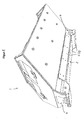
- Fig. 1 shows a protective floor 2 with U-profiles 3 for vehicle 1 (partially shown in FIG Fig. 2 ). These are turned with the opening to the floor panel 4 of the vehicle 1 parallel to each other ( Fig. 2 ) or in a cross pattern 10 ( Fig. 3 - For example, a tracked vehicle) arranged.
- the pattern and the distance between the U-profiles 3 is vehicle-specific and is thus usually specified by the respective vehicle type.
- Additional, laterally extending crimping tubes 5 prevent the mine protection plates 6, 9 from being drawn around the lateral edges when the soil is dented (constriction).
- U-profiles 3 profiles 7, preferably square profiles are inserted. These are provided with threaded holes 11.
- the U-profiles 3 have with these threaded holes corresponding holes / holes or a narrow slot or the like (not shown in detail).
- recesses 12 are provided in the squeeze tubes.
- the lateral square sections 7 are provided with attached rods 13, through which the square sections 7 can be fixed before screwing.
- the stiff composite withstands the load and prevents or reduces the damage to the vehicle 1.
- a projectile-forming mine eg TMRP 7 acts the steel sandwich 9, 6. The projectile is broken by the first, harder plate 6 and the fragments etc. held by the second softer sheet 9.
- the different hardness and thickness of the additional and the base plates allow a variation of the protective properties, so that by replacing the additional plates against thicker plates, the level of protection can be adapted to the threat scenario.
Abstract
Description
Die Erfindung beschäftigt sich mit einem Stahl - Sandwich - Minenschutz insbesondere für horizontale Böden bei Fahrzeugen.The invention is concerned with a steel sandwich mine protection, in particular for horizontal floors in vehicles.
Eine Panzerung zur Abwehr eines Wuchtgeschosses mit Schutzelementen bevorzugt aus Stahl beschreibt die
Ein gepanzertes Fahrzeug ist der
Eine Vorrichtung zur Befestigung von Panzerelementen wird zudem in der
Eine Vorrichtung zur Panzerung beschreibt des Weiteren die
Eine weitere Vorrichtung zum Schutz eines gepanzerten Fahrzeuges gibt die
Ein Panzerungselement aus Beschuss hemmenden Gewebematten oder Formteilen offenbart die
Mit einer minengeschützten Wannenstruktur beschäftigt sich die
Ein Verfahren zur Befestigung einer Zusatzpanzerung kann der
Ein Durchschuss hemmendes Wandungselement offenbart zudem die
Die
Eine Sandwich- Struktur in der
Aus der
In der nicht vorveröffentlichten
Die
Hier stellt sich die Erfindung die Aufgabe, einen einfachen Minenschutz aufzuzeigen, der einen ausreichenden Schutz gegen projektilbildende Minen und/oder gegen Blastminen insbesondere von unten gewährleistet.Here, the invention has the object to show a simple mine protection, which ensures adequate protection against projectile-forming mines and / or blast mines, especially from below.
Gelöst wird die Aufgabe durch die Merkmale des Patentanspruchs 1. Vorteilhafte Ausführungen sind in den Unteransprüchen enthalten.The object is achieved by the features of
Der Erfindung liegt die Idee zugrunde, U-Profile einzubinden, die für den Abstand zwischen einem Stahl- Sandwich und der Fahrzeugaußenwand bzw. dem Fahrzeugboden sorgen und gleichzeitig Befestigungsschrauben für den Anbau der Minenschutzplatten aufnehmen können. Zur Aufnahme der Befestigungsschrauben sind weitere Vierkantprofile mit Gewindebohrungen vorgesehen, die in die U-Profile etc. eingeschoben werden können. So wird sichergestellt, dass bei Explosion die Muttern nicht als Geschosse wirken, die dann den Fahrzeugboden durchschlagen können. Zudem können nach Beschädigung des Minenschutzes die Schraubverbindung einfacher ausgetauscht werden. Durch die Einbindung der weiteren (Vierkant-)Profile ist es zudem unwichtig, ob die Schrauben abgerissen und/oder die Gewinde zerstört wurden, da das gesamte Profil (als Ganzes) ausgetauscht werden kann.The invention is based on the idea to incorporate U-profiles that provide the distance between a steel sandwich and the vehicle outer wall or the vehicle floor and at the same time can accommodate mounting screws for the cultivation of mine protection plates. To accommodate the mounting screws further square profiles are provided with threaded holes that can be inserted into the U-profiles, etc. This ensures that in case of an explosion, the nuts do not act as projectiles, which can then penetrate the vehicle floor. In addition, after damage to the mine protection, the screw can be replaced easily. By integrating the other (square) profiles, it is also unimportant whether the screws were torn off and / or the threads were destroyed because the entire profile (as a whole) can be replaced.
Eine reine Stahl- Lösung des Minenschutzes bzw. des Sandwichs wird bevorzugt, ist aber nicht Bedingung. Ein Aufbau mit zwei oder mehreren Stahlplatten reduziert die notwendige Dicke einer einzelnen Platte, um den ausreichenden Schutz zu gewähren.A pure steel solution of the mine protection or the sandwich is preferred, but is not a requirement. A structure with two or more steel plates reduces the necessary thickness of a single plate to provide adequate protection.
Die um die seitlichen Kanten des Fahrzeugbodens herum gebogenen Platten sorgen ihrerseits für eine günstige Krafteinleitung und stellen einen zusätzlichen EFP-Schutz (Explosively-Formed Penetrator) dar. Mit den gebogenen Kanten ist es zudem möglich, beispielsweise bei einem Kettenfahrzeug den seitlichen Bereich zwischen den Laufrollen zusätzlich auch gegen EFP's zu schützen.The curved around the lateral edges of the vehicle floor panels in turn provide for a favorable force application and provide an additional EFP protection (Explosively-Formed Penetrator). With the curved edges, it is also possible, for example in a tracked vehicle, the lateral area between the rollers in addition to protect against EFP's.
Der vorgeschlagene Minenschutzboden wird dabei durch die konstruktiven Maßnahmen so stark versteift, dass der durch die Explosion entstehende Blastdruck nur geringe Einbeulungen verursachen kann. Das Projektil der projektilbildenden Mine (EFP) wird hingegen daran gehindert, den Fahrzeugboden zu durchschlagen. Der Minenschutz kann verändert und auf spezifische Bedrohungen ausgerichtet werden. Die einfache Montage bzw. Befestigung des Schutzes erlaubt eine Reparatur bzw. einen Wechsel des Schutzes vor Ort. Sie sind zudem kostengünstiger als geklebte Sandwich-Böden mit Kunststoff oder ähnlichen Schichten.The proposed mine protection floor is so strongly stiffened by the constructive measures that the blast pressure resulting from the explosion can only cause small denting. The projectile of the projectile-forming mine (EFP), however, is prevented from penetrating the vehicle floor. The mine protection can be changed and aligned to specific threats. The simple installation or attachment of the protection allows a repair or a change of protection on site. They are also less expensive than glued sandwich floors with plastic or similar layers.
Anhand eines Ausführungsbeispiels mit Zeichnung soll die Erfindung näher erläutert werden. Es zeigt:
- Fig. 1
- einen Schutzboden als Stahl - Sandwich in einer Draufsicht mit parallel zum Bodenblech ausgerichteten U-Profilen,
- Fig. 2
- den Stahl - Sandwich - Schutzboden aus
Fig. 1 an einem Fahrzeug, - Fig. 3
- eine Unteransicht eines Kettenfahrzeuges mit in einem Kreuzmuster zum Bo- denblech des Fahrzeugs ausgerichteten U-Profilen.
- Fig. 1
- a protective floor as a steel sandwich in a plan view with U-profiles aligned parallel to the floor panel,
- Fig. 2
- the steel sandwich protection floor
Fig. 1 on a vehicle, - Fig. 3
- a bottom view of a tracked vehicle with U-profiles aligned in a cross pattern to the bottom plate of the vehicle.
In die U-Profile 3 werden Profile 7, vorzugsweise Vierkantprofile eingeschoben. Diese sind mit Gewindebohrungen 11 versehen. Die U-Profile 3 besitzen mit diesen Gewindebohrungen korrespondierende Bohrungen/Löcher oder ein schmales Langloch oder dergleichen (nicht näher dargestellt). Für das vollständige Einschieben sind in den Quetschrohren 5 Aussparungen 12 vorgesehen. Zur besseren Montierbarkeit sind die seitlichen Vierkantprofile 7 mit aufgesetzten Rundstäben 13 versehen, durch die die Vierkantprofile 7 vor dem Verschrauben fixiert werden können.In the U-profiles 3 profiles 7, preferably square profiles are inserted. These are provided with threaded
Auf die U-Profile 3 werden zwei oder mehrere Stahlplatten 9, 6 geschraubt. Es entsteht ein Verbund aus Fahrzeugboden 4 (Basisplatten) - Luftspalt - und Stahlsandwich (Zusatzplatten 9, 6), der bei Explosion nur wenig einbeult. Der Luftspalt zwischen dem Fahrzeugboden 4 und dem Sandwich 9, 6 stellt sich dabei durch die Höhe/Form der U-Profile 3 ein.On the U-profiles 3, two or
Bei einer Explosion einer Blastmine hält somit der steife Verbund der Belastung stand und verhindert bzw. verringert die Beschädigung am Fahrzeug 1. Bei einer Explosion einer projektilbildenden Mine (z. B. TMRP 7) wirkt das Stahl-Sandwich 9, 6. Das Projektil wird durch die erste, härtere Platte 6 gebrochen und die Fragmente etc. vom zweiten weicheren Blech 9 gehalten.In an explosion of a blast mine thus the stiff composite withstands the load and prevents or reduces the damage to the
Als vorteilhaft hat sich gezeigt, die beiden Bleche nur am Rand (und an den U-Profilen) zu verschrauben, damit sich die Bleche 6, 9 unabhängig voneinander einbeulen können.It has proven to be advantageous to screw the two sheets only on the edge (and on the U-profiles), so that the
Die unterschiedliche Härte und Dicke der Zusatz- und der Basisplatten ermöglichen ein Variieren der Schutzeigenschaften, sodass durch Austausch der Zusatzplatten gegen dickere Platten das Schutzniveau dem Bedrohungsszenario angepasst werden kann.The different hardness and thickness of the additional and the base plates allow a variation of the protective properties, so that by replacing the additional plates against thicker plates, the level of protection can be adapted to the threat scenario.
Claims (7)
Applications Claiming Priority (1)
| Application Number | Priority Date | Filing Date | Title |
|---|---|---|---|
| DE102009033563A DE102009033563A1 (en) | 2009-07-16 | 2009-07-16 | mine protection |
Publications (3)
| Publication Number | Publication Date |
|---|---|
| EP2275773A2 true EP2275773A2 (en) | 2011-01-19 |
| EP2275773A3 EP2275773A3 (en) | 2012-07-25 |
| EP2275773B1 EP2275773B1 (en) | 2013-09-11 |
Family
ID=42799879
Family Applications (1)
| Application Number | Title | Priority Date | Filing Date |
|---|---|---|---|
| EP20100006649 Active EP2275773B1 (en) | 2009-07-16 | 2010-06-26 | Mine protection |
Country Status (3)
| Country | Link |
|---|---|
| EP (1) | EP2275773B1 (en) |
| DE (1) | DE102009033563A1 (en) |
| ES (1) | ES2437667T3 (en) |
Cited By (6)
| Publication number | Priority date | Publication date | Assignee | Title |
|---|---|---|---|---|
| US8240239B1 (en) | 2011-07-16 | 2012-08-14 | Kevin Mark Diaz | Green energy mine defeat system |
| WO2013036924A1 (en) * | 2011-09-09 | 2013-03-14 | Bae Systems Land & Armaments L.P. | Armored vehicle with bolt-on bottom |
| EP2997324B1 (en) | 2013-05-15 | 2018-04-11 | NEXTER Systems | Floor structure for an armoured vehicle body |
| EP3012571B1 (en) | 2010-04-23 | 2018-06-13 | Krauss-Maffei Wegmann GmbH & Co. KG | Vehicle floor pan comprising additional armouring |
| CN111649116A (en) * | 2020-05-07 | 2020-09-11 | 南京理工大学 | Impact-resistant protection device for vehicle transfer case |
| CN114475810A (en) * | 2022-02-18 | 2022-05-13 | 北京汽车集团越野车有限公司 | Floor assembly and vehicle |
Citations (14)
| Publication number | Priority date | Publication date | Assignee | Title |
|---|---|---|---|---|
| DE3633349A1 (en) | 1986-10-01 | 1988-04-14 | Jung Akustik Gmbh | Shot-penetration resistant (bulletproof) wall element for protection of industrial plants, production machines and such apparatuses |
| DE4310737A1 (en) | 1993-04-01 | 1994-10-06 | Deutsch Franz Forsch Inst | Armour |
| DE4426082A1 (en) | 1993-07-22 | 1995-01-26 | Giat Ind Sa | Device for fastening armored elements to a receiving structure, in particular to an armored vehicle |
| DE4314094C2 (en) | 1992-07-11 | 1996-10-31 | Wendler Karosseriebau Gmbh | Armored vehicle |
| DE19649709A1 (en) | 1996-11-29 | 1998-06-04 | Diehl Gmbh & Co | Reactive armour for tank |
| DE19900716A1 (en) | 1998-01-29 | 1999-08-12 | Sachsenring Entwicklungsgesell | Armor component, particularly for security vehicle |
| DE19842629C1 (en) | 1998-09-17 | 2000-03-16 | Daimler Chrysler Ag | Armor for vehicle for protection of vehicle interior comprises protective component fixed to inside of vehicle outer covering, facing vehicle interior, by at least one fixture component |
| WO2004011871A1 (en) | 2002-07-24 | 2004-02-05 | Société Nouvelle Des Automobiles Auverland (S.N.A.A.) | Sandwich structure |
| DE10258411A1 (en) | 2002-12-13 | 2004-07-08 | Blohm + Voss Gmbh | Armor device |
| WO2004088238A1 (en) | 2003-04-01 | 2004-10-14 | Geke Technologie Gmbh | Anti-mine arrangement |
| EP1564520A2 (en) | 2004-02-05 | 2005-08-17 | Steyr-Daimler-Puch Spezialfahrzeug AG & Co. KG | Hull structure of an armored vehicle with protection against landmines |
| DE102007005301A1 (en) | 2007-02-02 | 2008-08-07 | Audi Ag | Protective armor for use on side door of passenger car, has bullet proof steel plates which are curved or enclosed at one angle for adjustment to outer body design of vehicle, where one steel plate is strengthened by deposit welding |
| EP2017569A1 (en) | 2007-07-18 | 2009-01-21 | Steyr-Daimler-Puch Spezialfahrzeug GmbH | Method for mounting add-on armour and mounting produced according to the method |
| DE102009012251A1 (en) | 2009-03-07 | 2010-09-09 | Rheinmetall Landsysteme Gmbh | Protective device for protecting an object against projectile-forming mines |
Family Cites Families (10)
| Publication number | Priority date | Publication date | Assignee | Title |
|---|---|---|---|---|
| US4351558A (en) * | 1979-04-23 | 1982-09-28 | Mueller Frederick N | Truck body construction |
| US5670734A (en) * | 1994-10-05 | 1997-09-23 | United Defense, L.P. | Modular armor mounting system |
| DE29500711U1 (en) * | 1995-01-18 | 1996-05-30 | Thyssen Industrie | Protective wall for shelters, storage spaces or the like. and kit intended for their manufacture |
| DE19945257A1 (en) * | 1999-09-21 | 2001-03-22 | Bayerische Motoren Werke Ag | Bullet-proof car has plates connected by nuts and bolts, socket mounted in bore in one plate having first section which surrounds nut and second section enclosing bolt head and welded to other plate |
| EP1182420A1 (en) * | 2000-08-23 | 2002-02-27 | SW Schweizerische Unternehmung für Waffensysteme AG | System for protecting a vehicle against the effects of an explosive charge |
| DE10134394B4 (en) * | 2001-07-14 | 2004-02-12 | Rheinmetall Landsysteme Gmbh | Mine protection floor for an armored vehicle |
| US6523460B1 (en) * | 2001-07-31 | 2003-02-25 | Rita T. Lange | Skillet with interchangeable perforated bottom plates |
| DE20201005U1 (en) * | 2002-01-24 | 2002-07-04 | Krauss Maffei Wegmann Gmbh & C | Armored vehicle, especially battle tanks |
| DE202004007765U1 (en) * | 2004-05-13 | 2005-09-22 | Ah Worldwide Lp, Edinburgh | Double armour plating for fighting vehicle or vehicle carrying civilians threatened by explosion or gunfire |
| WO2008127272A1 (en) * | 2006-09-12 | 2008-10-23 | Protected Vehicles, Inc. | Systems and methods for enhancing the protection provided by armored vehicles |
-
2009
- 2009-07-16 DE DE102009033563A patent/DE102009033563A1/en not_active Withdrawn
-
2010
- 2010-06-26 EP EP20100006649 patent/EP2275773B1/en active Active
- 2010-06-26 ES ES10006649T patent/ES2437667T3/en active Active
Patent Citations (14)
| Publication number | Priority date | Publication date | Assignee | Title |
|---|---|---|---|---|
| DE3633349A1 (en) | 1986-10-01 | 1988-04-14 | Jung Akustik Gmbh | Shot-penetration resistant (bulletproof) wall element for protection of industrial plants, production machines and such apparatuses |
| DE4314094C2 (en) | 1992-07-11 | 1996-10-31 | Wendler Karosseriebau Gmbh | Armored vehicle |
| DE4310737A1 (en) | 1993-04-01 | 1994-10-06 | Deutsch Franz Forsch Inst | Armour |
| DE4426082A1 (en) | 1993-07-22 | 1995-01-26 | Giat Ind Sa | Device for fastening armored elements to a receiving structure, in particular to an armored vehicle |
| DE19649709A1 (en) | 1996-11-29 | 1998-06-04 | Diehl Gmbh & Co | Reactive armour for tank |
| DE19900716A1 (en) | 1998-01-29 | 1999-08-12 | Sachsenring Entwicklungsgesell | Armor component, particularly for security vehicle |
| DE19842629C1 (en) | 1998-09-17 | 2000-03-16 | Daimler Chrysler Ag | Armor for vehicle for protection of vehicle interior comprises protective component fixed to inside of vehicle outer covering, facing vehicle interior, by at least one fixture component |
| WO2004011871A1 (en) | 2002-07-24 | 2004-02-05 | Société Nouvelle Des Automobiles Auverland (S.N.A.A.) | Sandwich structure |
| DE10258411A1 (en) | 2002-12-13 | 2004-07-08 | Blohm + Voss Gmbh | Armor device |
| WO2004088238A1 (en) | 2003-04-01 | 2004-10-14 | Geke Technologie Gmbh | Anti-mine arrangement |
| EP1564520A2 (en) | 2004-02-05 | 2005-08-17 | Steyr-Daimler-Puch Spezialfahrzeug AG & Co. KG | Hull structure of an armored vehicle with protection against landmines |
| DE102007005301A1 (en) | 2007-02-02 | 2008-08-07 | Audi Ag | Protective armor for use on side door of passenger car, has bullet proof steel plates which are curved or enclosed at one angle for adjustment to outer body design of vehicle, where one steel plate is strengthened by deposit welding |
| EP2017569A1 (en) | 2007-07-18 | 2009-01-21 | Steyr-Daimler-Puch Spezialfahrzeug GmbH | Method for mounting add-on armour and mounting produced according to the method |
| DE102009012251A1 (en) | 2009-03-07 | 2010-09-09 | Rheinmetall Landsysteme Gmbh | Protective device for protecting an object against projectile-forming mines |
Cited By (7)
| Publication number | Priority date | Publication date | Assignee | Title |
|---|---|---|---|---|
| EP3012571B1 (en) | 2010-04-23 | 2018-06-13 | Krauss-Maffei Wegmann GmbH & Co. KG | Vehicle floor pan comprising additional armouring |
| US8240239B1 (en) | 2011-07-16 | 2012-08-14 | Kevin Mark Diaz | Green energy mine defeat system |
| WO2013036924A1 (en) * | 2011-09-09 | 2013-03-14 | Bae Systems Land & Armaments L.P. | Armored vehicle with bolt-on bottom |
| US8998299B2 (en) | 2011-09-09 | 2015-04-07 | Bae Systems Land & Armaments, L.P. | Armored vehicle with bolt-on bottom |
| EP2997324B1 (en) | 2013-05-15 | 2018-04-11 | NEXTER Systems | Floor structure for an armoured vehicle body |
| CN111649116A (en) * | 2020-05-07 | 2020-09-11 | 南京理工大学 | Impact-resistant protection device for vehicle transfer case |
| CN114475810A (en) * | 2022-02-18 | 2022-05-13 | 北京汽车集团越野车有限公司 | Floor assembly and vehicle |
Also Published As
| Publication number | Publication date |
|---|---|
| EP2275773B1 (en) | 2013-09-11 |
| EP2275773A3 (en) | 2012-07-25 |
| ES2437667T3 (en) | 2014-01-13 |
| DE102009033563A1 (en) | 2011-01-20 |
Similar Documents
| Publication | Publication Date | Title |
|---|---|---|
| EP1566607B1 (en) | Vehicle floor for land mine protection | |
| EP2275773B1 (en) | Mine protection | |
| DE19913845C2 (en) | Device to ensure the availability of military vehicles | |
| DE10134394A1 (en) | Mine protection floor for an armored vehicle | |
| EP3417231B1 (en) | Device and system for absorbing energy | |
| DE19605230A1 (en) | Anti-mine protection system for military vehicle | |
| EP2806245B1 (en) | Protective device against projectiles | |
| DE19707462C1 (en) | Armoured road vehicle with reinforced bodywork chassis parts | |
| EP2226603A2 (en) | Protection device for protecting an object against projectile forming mines | |
| DE102004027767B4 (en) | System for fixing protective plates against fire | |
| DE102005060604B3 (en) | Armored car, comprises particularly strong shell-proof profile inserted into gap around door | |
| EP0992383B1 (en) | Door system for utility vehicles | |
| DE102006050130A1 (en) | Multi-layered, armor plating material, has ceramic or metal bodies arranged on support layer such that large surface of position lies against support layer by one body, where another body of another position is inserted into gaps | |
| DE3730371A1 (en) | Welded joint arrangement for armour bulkhead plates | |
| EP0578085A1 (en) | Armoured vehicle-door | |
| DE102005020657A1 (en) | Corrugated outer metal skin for armoured fighting vehicle is maintained at a distance from armoured structure by spacers | |
| DE102007050658B4 (en) | Flat composite armor element | |
| EP0933612A2 (en) | Armour | |
| DE102014226015A1 (en) | Screw and use a screw | |
| EP4045868B1 (en) | Underbody of a vehicle with mine protection | |
| DE10231607B4 (en) | armor panel | |
| DE102008049933A1 (en) | Mint protection seat cover for vehicle seats | |
| EP2372047B1 (en) | Explosion and shot-inhibiting structure and method for producing same | |
| DE102007002210B4 (en) | Plate for a bullet resistant armor | |
| WO2016146571A1 (en) | Protective structure for an armored vehicle |
Legal Events
| Date | Code | Title | Description |
|---|---|---|---|
| PUAI | Public reference made under article 153(3) epc to a published international application that has entered the european phase |
Free format text: ORIGINAL CODE: 0009012 |
|
| AK | Designated contracting states |
Kind code of ref document: A2 Designated state(s): AL AT BE BG CH CY CZ DE DK EE ES FI FR GB GR HR HU IE IS IT LI LT LU LV MC MK MT NL NO PL PT RO SE SI SK SM TR |
|
| AX | Request for extension of the european patent |
Extension state: BA ME RS |
|
| PUAL | Search report despatched |
Free format text: ORIGINAL CODE: 0009013 |
|
| AK | Designated contracting states |
Kind code of ref document: A3 Designated state(s): AL AT BE BG CH CY CZ DE DK EE ES FI FR GB GR HR HU IE IS IT LI LT LU LV MC MK MT NL NO PL PT RO SE SI SK SM TR |
|
| AX | Request for extension of the european patent |
Extension state: BA ME RS |
|
| RIC1 | Information provided on ipc code assigned before grant |
Ipc: F41H 5/013 20060101ALN20120618BHEP Ipc: F41H 7/04 20060101AFI20120618BHEP |
|
| 17P | Request for examination filed |
Effective date: 20130125 |
|
| RIC1 | Information provided on ipc code assigned before grant |
Ipc: F41H 7/04 20060101AFI20130227BHEP Ipc: F41H 5/013 20060101ALN20130227BHEP |
|
| GRAP | Despatch of communication of intention to grant a patent |
Free format text: ORIGINAL CODE: EPIDOSNIGR1 |
|
| RIC1 | Information provided on ipc code assigned before grant |
Ipc: F41H 5/013 20060101ALN20130318BHEP Ipc: F41H 7/04 20060101AFI20130318BHEP |
|
| INTG | Intention to grant announced |
Effective date: 20130412 |
|
| GRAS | Grant fee paid |
Free format text: ORIGINAL CODE: EPIDOSNIGR3 |
|
| GRAA | (expected) grant |
Free format text: ORIGINAL CODE: 0009210 |
|
| AK | Designated contracting states |
Kind code of ref document: B1 Designated state(s): AL AT BE BG CH CY CZ DE DK EE ES FI FR GB GR HR HU IE IS IT LI LT LU LV MC MK MT NL NO PL PT RO SE SI SK SM TR |
|
| REG | Reference to a national code |
Ref country code: GB Ref legal event code: FG4D Free format text: NOT ENGLISH |
|
| REG | Reference to a national code |
Ref country code: CH Ref legal event code: EP |
|
| REG | Reference to a national code |
Ref country code: AT Ref legal event code: REF Ref document number: 631883 Country of ref document: AT Kind code of ref document: T Effective date: 20130915 |
|
| REG | Reference to a national code |
Ref country code: IE Ref legal event code: FG4D Free format text: LANGUAGE OF EP DOCUMENT: GERMAN |
|
| REG | Reference to a national code |
Ref country code: DE Ref legal event code: R096 Ref document number: 502010004662 Country of ref document: DE Effective date: 20131107 |
|
| REG | Reference to a national code |
Ref country code: CH Ref legal event code: NV Representative=s name: WEINMANN ZIMMERLI, CH |
|
| RAP2 | Party data changed (patent owner data changed or rights of a patent transferred) |
Owner name: RHEINMETALL LANDSYSTEME GMBH |
|
| REG | Reference to a national code |
Ref country code: ES Ref legal event code: FG2A Ref document number: 2437667 Country of ref document: ES Kind code of ref document: T3 Effective date: 20140113 |
|
| PG25 | Lapsed in a contracting state [announced via postgrant information from national office to epo] |
Ref country code: SE Free format text: LAPSE BECAUSE OF FAILURE TO SUBMIT A TRANSLATION OF THE DESCRIPTION OR TO PAY THE FEE WITHIN THE PRESCRIBED TIME-LIMIT Effective date: 20130911 Ref country code: LT Free format text: LAPSE BECAUSE OF FAILURE TO SUBMIT A TRANSLATION OF THE DESCRIPTION OR TO PAY THE FEE WITHIN THE PRESCRIBED TIME-LIMIT Effective date: 20130911 Ref country code: HR Free format text: LAPSE BECAUSE OF FAILURE TO SUBMIT A TRANSLATION OF THE DESCRIPTION OR TO PAY THE FEE WITHIN THE PRESCRIBED TIME-LIMIT Effective date: 20130911 Ref country code: CY Free format text: LAPSE BECAUSE OF FAILURE TO SUBMIT A TRANSLATION OF THE DESCRIPTION OR TO PAY THE FEE WITHIN THE PRESCRIBED TIME-LIMIT Effective date: 20130918 Ref country code: NO Free format text: LAPSE BECAUSE OF FAILURE TO SUBMIT A TRANSLATION OF THE DESCRIPTION OR TO PAY THE FEE WITHIN THE PRESCRIBED TIME-LIMIT Effective date: 20131211 |
|
| REG | Reference to a national code |
Ref country code: NL Ref legal event code: VDEP Effective date: 20130911 |
|
| REG | Reference to a national code |
Ref country code: LT Ref legal event code: MG4D |
|
| PG25 | Lapsed in a contracting state [announced via postgrant information from national office to epo] |
Ref country code: FI Free format text: LAPSE BECAUSE OF FAILURE TO SUBMIT A TRANSLATION OF THE DESCRIPTION OR TO PAY THE FEE WITHIN THE PRESCRIBED TIME-LIMIT Effective date: 20130911 Ref country code: SI Free format text: LAPSE BECAUSE OF FAILURE TO SUBMIT A TRANSLATION OF THE DESCRIPTION OR TO PAY THE FEE WITHIN THE PRESCRIBED TIME-LIMIT Effective date: 20130911 Ref country code: GR Free format text: LAPSE BECAUSE OF FAILURE TO SUBMIT A TRANSLATION OF THE DESCRIPTION OR TO PAY THE FEE WITHIN THE PRESCRIBED TIME-LIMIT Effective date: 20131212 Ref country code: LV Free format text: LAPSE BECAUSE OF FAILURE TO SUBMIT A TRANSLATION OF THE DESCRIPTION OR TO PAY THE FEE WITHIN THE PRESCRIBED TIME-LIMIT Effective date: 20130911 |
|
| PG25 | Lapsed in a contracting state [announced via postgrant information from national office to epo] |
Ref country code: CY Free format text: LAPSE BECAUSE OF FAILURE TO SUBMIT A TRANSLATION OF THE DESCRIPTION OR TO PAY THE FEE WITHIN THE PRESCRIBED TIME-LIMIT Effective date: 20130911 |
|
| PG25 | Lapsed in a contracting state [announced via postgrant information from national office to epo] |
Ref country code: SK Free format text: LAPSE BECAUSE OF FAILURE TO SUBMIT A TRANSLATION OF THE DESCRIPTION OR TO PAY THE FEE WITHIN THE PRESCRIBED TIME-LIMIT Effective date: 20130911 Ref country code: EE Free format text: LAPSE BECAUSE OF FAILURE TO SUBMIT A TRANSLATION OF THE DESCRIPTION OR TO PAY THE FEE WITHIN THE PRESCRIBED TIME-LIMIT Effective date: 20130911 Ref country code: RO Free format text: LAPSE BECAUSE OF FAILURE TO SUBMIT A TRANSLATION OF THE DESCRIPTION OR TO PAY THE FEE WITHIN THE PRESCRIBED TIME-LIMIT Effective date: 20130911 Ref country code: CZ Free format text: LAPSE BECAUSE OF FAILURE TO SUBMIT A TRANSLATION OF THE DESCRIPTION OR TO PAY THE FEE WITHIN THE PRESCRIBED TIME-LIMIT Effective date: 20130911 Ref country code: IS Free format text: LAPSE BECAUSE OF FAILURE TO SUBMIT A TRANSLATION OF THE DESCRIPTION OR TO PAY THE FEE WITHIN THE PRESCRIBED TIME-LIMIT Effective date: 20140111 Ref country code: NL Free format text: LAPSE BECAUSE OF FAILURE TO SUBMIT A TRANSLATION OF THE DESCRIPTION OR TO PAY THE FEE WITHIN THE PRESCRIBED TIME-LIMIT Effective date: 20130911 |
|
| PG25 | Lapsed in a contracting state [announced via postgrant information from national office to epo] |
Ref country code: PL Free format text: LAPSE BECAUSE OF FAILURE TO SUBMIT A TRANSLATION OF THE DESCRIPTION OR TO PAY THE FEE WITHIN THE PRESCRIBED TIME-LIMIT Effective date: 20130911 |
|
| REG | Reference to a national code |
Ref country code: DE Ref legal event code: R097 Ref document number: 502010004662 Country of ref document: DE |
|
| PG25 | Lapsed in a contracting state [announced via postgrant information from national office to epo] |
Ref country code: PT Free format text: LAPSE BECAUSE OF FAILURE TO SUBMIT A TRANSLATION OF THE DESCRIPTION OR TO PAY THE FEE WITHIN THE PRESCRIBED TIME-LIMIT Effective date: 20140113 |
|
| PLBE | No opposition filed within time limit |
Free format text: ORIGINAL CODE: 0009261 |
|
| STAA | Information on the status of an ep patent application or granted ep patent |
Free format text: STATUS: NO OPPOSITION FILED WITHIN TIME LIMIT |
|
| 26N | No opposition filed |
Effective date: 20140612 |
|
| PG25 | Lapsed in a contracting state [announced via postgrant information from national office to epo] |
Ref country code: IT Free format text: LAPSE BECAUSE OF FAILURE TO SUBMIT A TRANSLATION OF THE DESCRIPTION OR TO PAY THE FEE WITHIN THE PRESCRIBED TIME-LIMIT Effective date: 20130911 |
|
| REG | Reference to a national code |
Ref country code: DE Ref legal event code: R097 Ref document number: 502010004662 Country of ref document: DE Effective date: 20140612 |
|
| PG25 | Lapsed in a contracting state [announced via postgrant information from national office to epo] |
Ref country code: DK Free format text: LAPSE BECAUSE OF FAILURE TO SUBMIT A TRANSLATION OF THE DESCRIPTION OR TO PAY THE FEE WITHIN THE PRESCRIBED TIME-LIMIT Effective date: 20130911 |
|
| PG25 | Lapsed in a contracting state [announced via postgrant information from national office to epo] |
Ref country code: LU Free format text: LAPSE BECAUSE OF FAILURE TO SUBMIT A TRANSLATION OF THE DESCRIPTION OR TO PAY THE FEE WITHIN THE PRESCRIBED TIME-LIMIT Effective date: 20140626 Ref country code: MC Free format text: LAPSE BECAUSE OF FAILURE TO SUBMIT A TRANSLATION OF THE DESCRIPTION OR TO PAY THE FEE WITHIN THE PRESCRIBED TIME-LIMIT Effective date: 20130911 |
|
| REG | Reference to a national code |
Ref country code: IE Ref legal event code: MM4A |
|
| REG | Reference to a national code |
Ref country code: FR Ref legal event code: ST Effective date: 20150227 |
|
| PG25 | Lapsed in a contracting state [announced via postgrant information from national office to epo] |
Ref country code: IE Free format text: LAPSE BECAUSE OF NON-PAYMENT OF DUE FEES Effective date: 20140626 |
|
| PG25 | Lapsed in a contracting state [announced via postgrant information from national office to epo] |
Ref country code: FR Free format text: LAPSE BECAUSE OF NON-PAYMENT OF DUE FEES Effective date: 20140630 |
|
| PG25 | Lapsed in a contracting state [announced via postgrant information from national office to epo] |
Ref country code: MT Free format text: LAPSE BECAUSE OF FAILURE TO SUBMIT A TRANSLATION OF THE DESCRIPTION OR TO PAY THE FEE WITHIN THE PRESCRIBED TIME-LIMIT Effective date: 20130911 |
|
| PG25 | Lapsed in a contracting state [announced via postgrant information from national office to epo] |
Ref country code: SM Free format text: LAPSE BECAUSE OF FAILURE TO SUBMIT A TRANSLATION OF THE DESCRIPTION OR TO PAY THE FEE WITHIN THE PRESCRIBED TIME-LIMIT Effective date: 20130911 |
|
| PG25 | Lapsed in a contracting state [announced via postgrant information from national office to epo] |
Ref country code: BG Free format text: LAPSE BECAUSE OF FAILURE TO SUBMIT A TRANSLATION OF THE DESCRIPTION OR TO PAY THE FEE WITHIN THE PRESCRIBED TIME-LIMIT Effective date: 20130911 |
|
| PG25 | Lapsed in a contracting state [announced via postgrant information from national office to epo] |
Ref country code: BE Free format text: LAPSE BECAUSE OF FAILURE TO SUBMIT A TRANSLATION OF THE DESCRIPTION OR TO PAY THE FEE WITHIN THE PRESCRIBED TIME-LIMIT Effective date: 20140630 Ref country code: HU Free format text: LAPSE BECAUSE OF FAILURE TO SUBMIT A TRANSLATION OF THE DESCRIPTION OR TO PAY THE FEE WITHIN THE PRESCRIBED TIME-LIMIT; INVALID AB INITIO Effective date: 20100626 Ref country code: TR Free format text: LAPSE BECAUSE OF FAILURE TO SUBMIT A TRANSLATION OF THE DESCRIPTION OR TO PAY THE FEE WITHIN THE PRESCRIBED TIME-LIMIT Effective date: 20130911 |
|
| REG | Reference to a national code |
Ref country code: AT Ref legal event code: MM01 Ref document number: 631883 Country of ref document: AT Kind code of ref document: T Effective date: 20150626 |
|
| PG25 | Lapsed in a contracting state [announced via postgrant information from national office to epo] |
Ref country code: AT Free format text: LAPSE BECAUSE OF NON-PAYMENT OF DUE FEES Effective date: 20150626 |
|
| PG25 | Lapsed in a contracting state [announced via postgrant information from national office to epo] |
Ref country code: MK Free format text: LAPSE BECAUSE OF FAILURE TO SUBMIT A TRANSLATION OF THE DESCRIPTION OR TO PAY THE FEE WITHIN THE PRESCRIBED TIME-LIMIT Effective date: 20130911 |
|
| PG25 | Lapsed in a contracting state [announced via postgrant information from national office to epo] |
Ref country code: AL Free format text: LAPSE BECAUSE OF FAILURE TO SUBMIT A TRANSLATION OF THE DESCRIPTION OR TO PAY THE FEE WITHIN THE PRESCRIBED TIME-LIMIT Effective date: 20130911 |
|
| PGFP | Annual fee paid to national office [announced via postgrant information from national office to epo] |
Ref country code: DE Payment date: 20220914 Year of fee payment: 14 |
|
| PGFP | Annual fee paid to national office [announced via postgrant information from national office to epo] |
Ref country code: GB Payment date: 20230620 Year of fee payment: 14 Ref country code: ES Payment date: 20230828 Year of fee payment: 14 Ref country code: CH Payment date: 20230702 Year of fee payment: 14 |