EP2275760A2 - Cooling device - Google Patents
Cooling device Download PDFInfo
- Publication number
- EP2275760A2 EP2275760A2 EP10169719A EP10169719A EP2275760A2 EP 2275760 A2 EP2275760 A2 EP 2275760A2 EP 10169719 A EP10169719 A EP 10169719A EP 10169719 A EP10169719 A EP 10169719A EP 2275760 A2 EP2275760 A2 EP 2275760A2
- Authority
- EP
- European Patent Office
- Prior art keywords
- fluid flow
- compartment
- cooling means
- deflector
- cooling
- Prior art date
- Legal status (The legal status is an assumption and is not a legal conclusion. Google has not performed a legal analysis and makes no representation as to the accuracy of the status listed.)
- Granted
Links
Images


Classifications
-
- F—MECHANICAL ENGINEERING; LIGHTING; HEATING; WEAPONS; BLASTING
- F25—REFRIGERATION OR COOLING; COMBINED HEATING AND REFRIGERATION SYSTEMS; HEAT PUMP SYSTEMS; MANUFACTURE OR STORAGE OF ICE; LIQUEFACTION SOLIDIFICATION OF GASES
- F25D—REFRIGERATORS; COLD ROOMS; ICE-BOXES; COOLING OR FREEZING APPARATUS NOT OTHERWISE PROVIDED FOR
- F25D17/00—Arrangements for circulating cooling fluids; Arrangements for circulating gas, e.g. air, within refrigerated spaces
- F25D17/04—Arrangements for circulating cooling fluids; Arrangements for circulating gas, e.g. air, within refrigerated spaces for circulating air, e.g. by convection
- F25D17/06—Arrangements for circulating cooling fluids; Arrangements for circulating gas, e.g. air, within refrigerated spaces for circulating air, e.g. by convection by forced circulation
- F25D17/062—Arrangements for circulating cooling fluids; Arrangements for circulating gas, e.g. air, within refrigerated spaces for circulating air, e.g. by convection by forced circulation in household refrigerators
- F25D17/065—Arrangements for circulating cooling fluids; Arrangements for circulating gas, e.g. air, within refrigerated spaces for circulating air, e.g. by convection by forced circulation in household refrigerators with compartments at different temperatures
Definitions
- This invention relates to a cooling device for foods. Particularly, it concerns a combined no-frost-type refrigerator/freezer (such devices are also known as no-frost fridge-freezers).
- the fluid of the first and of the second fluid flow after having been cooled by said finned evaporating device, is in fluid contact with the freezer compartment and periodically, by opening a specific valve, also with the refrigeration compartment. As a result, a cooling of the refrigerator compartment and of the freezer compartment is therefore achieved.
- the finned evaporating device is located in a chamber which is external to the freezer compartment and the refrigerator compartment.
- the first and the second fluid flows pour into said chamber, just underneath the finned evaporating device, and they then are transferred from the bottom to the top of the finned evaporating device .
- the technical task that is the objective of this invention is to propose a cooling device that overcomes the inconvenience of the known technique described above.
- the objective of this invention is to create a cooling device capable of improving the thermal efficiency.
- a further purpose of this invention is to propose a cooling device capable of facilitating and expediting assembly.
- cooling device has been indicated with reference number 1.
- Said cooling device 1 is specifically used to refrigerate foods for the purpose of allowing a longer-lasting preservation.
- Device 1 comprises a first cooled compartment 2 for the conservation of foods.
- Device 1 also comprises a second cooled compartment 3 for the conservation of foods.
- first and second compartments 2 and 3 could be two compartments refrigerated at different temperatures, for example one of the compartments could have a thermostat regulated at a nominal temperature greater than 0°C and the other compartment could have a thermostat regulated at a nominal temperature less than 0°C.
- humidity conditions of said compartments 2 and 3 may be different.
- the first cooled compartment 2 is conveniently a refrigerator compartment.
- a thermostat regulated at a nominal temperature ranging between 3°C and 8°C. Obviously, every thermostat also allows small temperature fluctuations (some centigrade degrees) around the nominal value.
- the second cooled compartment 3 is a freezer compartment. Normally in a freezer compartment there is a thermostat regulated at a nominal temperature comprised between -20°C and -10°C. In this case also, the thermostat allows for small temperature fluctuations around the nominal value.
- the first and the second compartments 2 and 3 could be, respectively, the freezer and the refrigerator compartments.
- Device 1 comprises a cooling means 4 of at least one first fluid flow 5 deriving from said first compartment 2 and of at least a second fluid flow 6 coming from said second compartment 3.
- the first fluid flow 5 is a flow of air.
- the second fluid flow 6 is a flow of air.
- the first fluid flow 5 is taken from the interior of the first compartment 2.
- the first fluid flow 5 has therefore the humidity and temperature conditions of the air present in the first compartment 2.
- the second fluid flow 6 is taken from the interior of the second compartment 3.
- the second fluid flow 6 has therefore the humidity and temperature conditions of the air present in the first compartment 3.
- the cooling means 4 comprises a finned evaporating device 41.
- the cooling means 4 are passed through by the first and by the second fluid flows 5 and 6.
- the finned evaporating device 41 is equipped with fins.
- the finned device 41 comprises of at least one first conduit 42 in which flows a corresponding first operative fluid flow diminishing the heat of the first and the second fluid flows 5 and 6, although remaining fluid-dynamically isolated from them.
- Said 'at least one first conduit' 42 is equipped with a number of fins 43.
- the fins 43 appropriately allow the improvement of the thermal exchange between the first operative fluid and the first and the second fluid flow 5 and 6.
- the device 1 also comprises deflector means 8 that are situated in proximity of an inlet 40 to the cooling means 4 of said first and/or of said second fluid flows 5 and 6.
- the deflector means 8 obstruct the mixing of the first and of the second fluid flows 5 and 6 (see for example Drawing 4, or 5 or 6 ).
- the deflector means 8 obstruct the mixing of the first and second fluid flows 5 and 6 at the inlet 40 of the first and of the second fluid flows 5 and 6 in the cooling means 4.
- the formation of ice in proximity of the cooling means 4 is also reduced.
- Said ice represents an obstruction that, in addition to worsening the fluid-dynamics, also reduces the efficiency of the thermal exchange.
- Heating means are strategically placed in the interior of the cooling means 4 that, when activated, contribute to melting, or in any case reducing the formation of, said ice.
- the heating means are usefully equipped with a resistance that is placed inside the cooling means 4.
- the deflector means 8 extend mainly in a vertical direction.
- the deflector means 8 direct at least one of the first and second fluid flows 5 and 6 towards at least one of the cooling means 4, separately from the one towards which the other fluid flow moves. Specifically, the deflector means 8 direct at least the second fluid flow 6. As a result, the controlled distribution of the first and of the second fluid flows 5 and 6 is obtained through the cooling means 4.
- the concentration of the fins 43 in the area towards which said fluid flow 5 is directed is different from the concentration of fins 43 in the area towards which the second fluid flow 6 is directed. Specifically, the concentration of fins 43 may be better examined case by case taking into account the possible humidity and temperature of the first and of the second fluid flows 5 and 6.
- the cooling means 4 are inside a chamber 7 in which flow said first and said second fluid flows 5 and 6.
- the chamber 7 is external to the first and to the second compartments 2 and 3. In the preferred case in which the second compartment 3 is a freezer compartment, the chamber 7 is appropriately placed adjacent to the second compartment 3.
- the cooling device 1 comprises the first conveyance means 12 of the first fluid flow 5 from the first compartment 2 to the chamber 7.
- said conveyance means 12 comprises a conduit 121 that extends itself from the first compartment 2 to the chamber 7.
- conduit 121 and the first compartment 2 is depicted as an exemplification, but not limited to, in the upper portion of the first compartment 2, but could also be placed corresponding to the lower portion, this would make it possible to obtain an optimal air circulation in the first compartment 2, particularly useful if vegetable containers are placed in the lower portion of the first compartment 2.
- the cooling device 1 also comprises a second conveyance means 13 for the second fluid flow 6 from the second compartment 3 to the chamber 7.
- Said second conveyance means 13 comprise at least one conduit 131 that extends from the first compartment 2 to the chamber 7.
- the deflector means 8 expand at least in part towards the interior of said chamber 7 in order to separate, at least in part, said first and said second fluid flows 5 and 6. Specifically, the deflector means 8 extend between the edge of chamber 7 and the cooling means 4. With regards to the direction of the flow of said first and said second fluid flows 5 and 6, said deflector means 8 extend at least in part over the cooling means 4.
- the cooling device 1 comprises at least a first opening 71 and at least a second opening 72.
- the device 1 can comprise at least a third opening 73.
- first and the second fluid flows 5 and 6 may flow into the chamber 7 through the first opening 71, whilst the other fluid flow may flow into the chamber 7 by means of said second and said third openings 72 and 73.
- the first opening 71 is substantially placed between the second and the third openings 72 and 73.
- said first fluid flow 5 flows into said chamber 7 and it is the second opening 72 that allows the second fluid flow 6 to enter into said chamber 7.
- the third opening 73 allows the second fluid flow 6 to enter into chamber 7.
- the deflector means 8 comprise:
- the second fluid flow 6, at least within the cooling means 4, provides two flows 6a and 6b, between which flows said first fluid flow 5. These two flows 6a and 6b of the second fluid flow 6 enter the chamber 7 from the second and from the third opening 72 and 73 respectively.
- the cooling means 4 are situated above the first, the second and the third openings 71, 72 and 73.
- the first fluid flow 5 will mostly affect the part of the cooling means 4 that intersects an imaginary vertical parallelepiped, a face of which is determined by the vertical projection of the first opening 71.
- the second fluid flow 6 will mostly affect the part of the cooling means 4 that intersects an imaginary vertical parallelepiped, a face of which is determined by the vertical projection of the second opening 72.
- the second fluid flow 6 will also affect the part of the cooling means 4 that intersects an imaginary vertical parallelepiped, a face of which is determined by the vertical projection of the third opening 73.
- the deflector means 8 contribute to obstruct the mixing of the first and of the second fluid flows 5 and 6.
- the first, the second and the third opening 71, 72 and 73, the first and the second deflectors 81 and 82 are symmetrically placed with respect to an imaginary plane 9.
- the chamber 7 is significantly symmetrical with respect to said imaginary plane 9.
- said imaginary plane 9 is vertical.
- the parallelepiped, that substantially envelops the exterior of the cooling means 4 (particularly the evaporating device 41), is significantly symmetrical with respect to the imaginary plane 9.
- the device 1 comprises a housing structure 10 for said cooling means 4.
- the housing structure 10 is situated inside the chamber 7.
- the housing structure 10 is bound inside said chamber 7.
- said housing structure 10 is bound by interference inside said chamber 7.
- the deflector means 8 are part of said housing structure 10. Specifically, the deflector means 8 are assembled with the remaining parts of the housing structure 10 in such a way that from a functional viewpoint, they are one unit. In an alternative solution, the deflector means 8 could structurally constitute one unit with the remaining parts of the housing structure 10.
- the housing structure 10 comprises a basic panel 101, that is preferably four-sided, corresponding to at least two opposite ends 102 and 103 of the basic panel 101, (and where there are) a first and a second fins 104 and 105 between which the cooling means 4 may be interposed.
- the basic panel 101 is adjoining a wall of the chamber 7.
- the first and the second fins 104 and 105 extend transversally to the basic panel 101 and preferably extend orthogonally to the basic panel 101.
- a third fin 107 extends along one side 106 of the basic panel 101 interposed between the first and the second fins 104 and 105. Helpfully, said third fin 107 connects the first and the second fins 104 and 105 (see Drawing 5 ).
- the basic panel 101, the first and the second fins 104 and 105 (and advantageously also the third fin 107) combined are placed in a concavity 108 in which the cooling means 4 are at least partially accommodated.
- the deflector means 8 extend from the basic panel 101.
- the deflector means 8 extend inside said concavity 108.
- Between the first deflector 81 and the first fin 104 is interposed the second opening 72.
- the first opening 71 is situated in fluid contact with the space interposed between the first and the second deflectors 81 and 82. Specifically, said first opening 71 is located above (with respect to the physical vertical) the space interposed between the first and the second deflectors 81 and 82.
- the fluid exiting from the second opening 72 is directed by the contribution of the first fin 104 and the first deflector 81.
- the fluid exiting from the third opening 73 is therefore directed by the contribution of the second fin 105 and the second deflector 82. Therefore, the fluid flow exiting from the second and from the third openings 72 and 73 is directed upwards along two imaginary corridors between which is interposed the first opening 71.
- the deflector means 8 will obstruct the movement of the fluid flow exiting from the second and from the third openings 72 and 73 towards the first opening 71 in order to minimize contact between two fluid flows 5 and 6 that have different thermodynamic properties.
- the housing structure 10 is made of thermo-insulating material.
- the basic panel 101 and/or the first and/or the second and/or the third fin 104, 105 and 107 and/or the deflector means 8 are made of thermo-insulating material.
- Said thermo-insulating material is, usefully, Styrofoam.
- an element that is made of thermo-conductor material is interposed between at least a portion of the housing structure 10 and the cooling means 4.
- said thermo-conductor material element is the coating of at least a portion of the housing structure 10. Said coating may affect the part of the housing structure 10 that is in contact with and/or interfaces the cooling means 4. Said coating reduces the risk of adhesion (due to the freezing of the humidity present in the air) of the cooling means 4 with the housing structure 10.
- Said coating usefully comprises a sheet of aluminum.
- the coating protects the housing structure 10 from the heat generated by the resistance that develops inside the cooling means 4.
- the cooling means 4 lean against the deflector means 8 (solution not shown) unloading onto them at least part of their weight.
- the deflector means 8 perform a double function: fluid-dynamic guide of the first and/or of the second fluid flows and structural, by contributing to sustaining the weight of the cooling means 4.
- said fluid is directed towards the freezer compartment and by means of an appropriate valve 17 (in the specific technical field said valve is normally called “damper") is periodically also directed toward the refrigerator compartment.
- a first duct 14 extends from the chamber 7, which allows to direct the flow of the first and of the second fluid flows 5 and 6 towards the first compartment 2 and a second duct 15 that allows to direct the flow of the first and of the second fluid flows 5 and 6 towards the second compartment 3.
- the first and the second compartments 2 and 3 are therefore cooled.
- Both the first and the second ducts 14 and 15 could comprise a number of interconnected conduits.
- the cooling device 1 usefully comprises fluid motion means 16.
- Said fluid motion means 16 are operatively interposed between the cooling means 4 and the first and/or the second ducts 14 and 15.
- Said fluid motion means 16 comprises a fan.
- Said fluid motion means 16 allow the extraction of fluid from the first and from the second fluid flows exiting from the cooling means 4 and direct it towards the first and/or the second ducts 15 and 16.
- the invention has important advantages.
- a further important advantage is connected to the increased speed and ease of assembly.
- the cooling means it will now be possible to connect the cooling means to the housing structure outside of the chamber and then insert them as a unit into the chamber.
- the speed of assembly saves time and/or reduce the number of operations performed on the assembly line.
- the cooling means 4 and the housing structure 10 may easily be preassembled obtaining a compact unit that can easily be attached to the remaining parts of the cooling device 1 directly along the assembly line (with simple positioning and attachment operations). Specifically, the positioning operation becomes much easier in the case that the housing structure 10 also has the function of supporting, at least in part, the cooling means 4.
Landscapes
- Engineering & Computer Science (AREA)
- Chemical & Material Sciences (AREA)
- Combustion & Propulsion (AREA)
- Physics & Mathematics (AREA)
- Mechanical Engineering (AREA)
- Thermal Sciences (AREA)
- General Engineering & Computer Science (AREA)
- Cold Air Circulating Systems And Constructional Details In Refrigerators (AREA)
- Devices That Are Associated With Refrigeration Equipment (AREA)
- Transition And Organic Metals Composition Catalysts For Addition Polymerization (AREA)
- Superconductors And Manufacturing Methods Therefor (AREA)
Abstract
-a first cooled compartment (2) for the preservation of food;
-a second cooled compartment (3) for the preservation of food;
-means (4) of cooling at least a first fluid flow (5) coming from the first compartment (2) and at least a second fluid flow (6) coming from the second compartment (3), the cooling means (4) being crossed by the first and the second fluid flow (5, 6);
-deflector means (8) extending close to an inlet (40) through which the first and/or the second fluid flow (5, 6) run into the cooling means (4), the deflector means (8) obstructing the mixing of the first and the second fluid flow (5, 6).
Description
- This invention relates to a cooling device for foods. Particularly, it concerns a combined no-frost-type refrigerator/freezer (such devices are also known as no-frost fridge-freezers).
- Well known are no-frost fridge-freezers comprising of:
- a refrigeration compartment for the preservation of foods;
- a freezer compartment for the preservation of foods;
- a finned evaporating device that cools at least a first fluid flow coming from said refrigerating compartment and at least a second fluid flow deriving from said freezing compartment.
- The fluid of the first and of the second fluid flow, after having been cooled by said finned evaporating device, is in fluid contact with the freezer compartment and periodically, by opening a specific valve, also with the refrigeration compartment. As a result, a cooling of the refrigerator compartment and of the freezer compartment is therefore achieved.
- The finned evaporating device is located in a chamber which is external to the freezer compartment and the refrigerator compartment. The first and the second fluid flows pour into said chamber, just underneath the finned evaporating device, and they then are transferred from the bottom to the top of the finned evaporating device .
- An inconvenience of these no-frost fridge-freezers is that the first and the second fluid flows are mixed, at least in part, when entering the finned evaporating device. The contact of a cold fluid flow coming from the freezer compartment and a fluid flow which is warmer and more humid coming from the refrigerator compartment increases the probability of a block of ice forming at the entrance of the finned evaporating device. Said block of ice may obstruct a large part of the finned evaporating device thus reducing the efficiency of its thermal exchange and may generate turbulence that can cause dynamic fluid leakage and noise.
- In this context, the technical task that is the objective of this invention is to propose a cooling device that overcomes the inconvenience of the known technique described above.
- Particularly, the objective of this invention is to create a cooling device capable of improving the thermal efficiency.
- A further purpose of this invention is to propose a cooling device capable of facilitating and expediting assembly.
- The defined technical task and the specified objectives are substantially achieved by means of a cooling device, comprising the technical characteristics described in one or more of the attached claims.
- Further characteristics and advantages of this invention will become clearer from the indicative, but not limited to, description of the preferred, although non-exclusive, embodiment of a cooling device, as illustrated in the attached Drawings, in which:
-
Drawing 1 shows a schematic view of a section of the cooling device; -
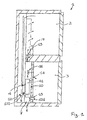
Drawing 2 shows a section view of a portion of the cooling device; -
Drawing 3 shows a perspective view of what is illustrated inDrawing 2 -
Drawing 4 shows a perspective view of an element of the cooling device; -
Drawings - With reference to the attached Drawings, the cooling device has been indicated with reference number 1. Said cooling device 1 is specifically used to refrigerate foods for the purpose of allowing a longer-lasting preservation.
- Device 1 comprises a first cooled
compartment 2 for the conservation of foods. Device 1 also comprises a second cooledcompartment 3 for the conservation of foods. - Appropriately the first and
second compartments - Also depending on the type of foods kept in the first and in the
second compartments compartments - In the preferred solution, the first cooled
compartment 2 is conveniently a refrigerator compartment. Normally, in a refrigerator compartment there is a thermostat regulated at a nominal temperature ranging between 3°C and 8°C. Obviously, every thermostat also allows small temperature fluctuations (some centigrade degrees) around the nominal value. - In the preferred solution, the second cooled
compartment 3 is a freezer compartment. Normally in a freezer compartment there is a thermostat regulated at a nominal temperature comprised between -20°C and -10°C. In this case also, the thermostat allows for small temperature fluctuations around the nominal value. - In an alternative solution, which is not illustrated, the first and the
second compartments - Device 1 comprises a cooling means 4 of at least one
first fluid flow 5 deriving from saidfirst compartment 2 and of at least asecond fluid flow 6 coming from saidsecond compartment 3. - Appropriately, the
first fluid flow 5 is a flow of air. Appropriately, thesecond fluid flow 6 is a flow of air. - The
first fluid flow 5 is taken from the interior of thefirst compartment 2. Thefirst fluid flow 5 has therefore the humidity and temperature conditions of the air present in thefirst compartment 2. - Similarly, the
second fluid flow 6 is taken from the interior of thesecond compartment 3. Thesecond fluid flow 6 has therefore the humidity and temperature conditions of the air present in thefirst compartment 3. - Usefully, the cooling means 4 comprises a finned
evaporating device 41. - The cooling means 4 are passed through by the first and by the second fluid flows 5 and 6.
- Usefully, the finned
evaporating device 41 is equipped with fins. Thefinned device 41 comprises of at least onefirst conduit 42 in which flows a corresponding first operative fluid flow diminishing the heat of the first and the second fluid flows 5 and 6, although remaining fluid-dynamically isolated from them. Said 'at least one first conduit' 42 is equipped with a number offins 43. Thefins 43 appropriately allow the improvement of the thermal exchange between the first operative fluid and the first and thesecond fluid flow fins 43 and saidfirst conduit 42. - Usefully, the device 1 also comprises deflector means 8 that are situated in proximity of an
inlet 40 to the cooling means 4 of said first and/or of said second fluid flows 5 and 6. The deflector means 8 obstruct the mixing of the first and of the second fluid flows 5 and 6 (see for exampleDrawing 4, or 5 or 6 ). Specifically, the deflector means 8 obstruct the mixing of the first and second fluid flows 5 and 6 at theinlet 40 of the first and of the second fluid flows 5 and 6 in the cooling means 4. By reducing the mixing of the first and of the second fluid flows 5 and 6 the turbulence and the dynamic fluid leakages that would derive from two fluid flows mixing, are generally reduced. - Furthermore, by reducing the mixing of the first and second fluid flows 5 and 6, the formation of ice in proximity of the cooling means 4 is also reduced.
- Said ice represents an obstruction that, in addition to worsening the fluid-dynamics, also reduces the efficiency of the thermal exchange. Heating means are strategically placed in the interior of the cooling means 4 that, when activated, contribute to melting, or in any case reducing the formation of, said ice. The heating means are usefully equipped with a resistance that is placed inside the cooling means 4.
- The deflector means 8 extend mainly in a vertical direction.
- Appropriately, the deflector means 8 direct at least one of the first and second fluid flows 5 and 6 towards at least one of the cooling means 4, separately from the one towards which the other fluid flow moves. Specifically, the deflector means 8 direct at least the
second fluid flow 6. As a result, the controlled distribution of the first and of the second fluid flows 5 and 6 is obtained through the cooling means 4. Appropriately, the concentration of thefins 43 in the area towards which saidfluid flow 5 is directed is different from the concentration offins 43 in the area towards which thesecond fluid flow 6 is directed. Specifically, the concentration offins 43 may be better examined case by case taking into account the possible humidity and temperature of the first and of the second fluid flows 5 and 6. - As an exemplification, but not limited to indications in
Drawings 13 , the cooling means 4 are inside achamber 7 in which flow said first and said second fluid flows 5 and 6. - The
chamber 7 is external to the first and to thesecond compartments second compartment 3 is a freezer compartment, thechamber 7 is appropriately placed adjacent to thesecond compartment 3. - The cooling device 1 comprises the first conveyance means 12 of the
first fluid flow 5 from thefirst compartment 2 to thechamber 7. Appropriately, said conveyance means 12 comprises aconduit 121 that extends itself from thefirst compartment 2 to thechamber 7. - In
Drawing 1 , the interface betweenconduit 121 and thefirst compartment 2 is depicted as an exemplification, but not limited to, in the upper portion of thefirst compartment 2, but could also be placed corresponding to the lower portion, this would make it possible to obtain an optimal air circulation in thefirst compartment 2, particularly useful if vegetable containers are placed in the lower portion of thefirst compartment 2. - The cooling device 1 also comprises a second conveyance means 13 for the
second fluid flow 6 from thesecond compartment 3 to thechamber 7. Said second conveyance means 13 comprise at least oneconduit 131 that extends from thefirst compartment 2 to thechamber 7. - The deflector means 8 expand at least in part towards the interior of said
chamber 7 in order to separate, at least in part, said first and said second fluid flows 5 and 6. Specifically, the deflector means 8 extend between the edge ofchamber 7 and the cooling means 4. With regards to the direction of the flow of said first and said second fluid flows 5 and 6, said deflector means 8 extend at least in part over the cooling means 4. - The cooling device 1 comprises at least a
first opening 71 and at least asecond opening 72. Usefully, the device 1 can comprise at least athird opening 73. - One between the first and the second fluid flows 5 and 6 may flow into the
chamber 7 through thefirst opening 71, whilst the other fluid flow may flow into thechamber 7 by means of said second and saidthird openings first opening 71 is substantially placed between the second and thethird openings - Usefully, through said
opening 71, saidfirst fluid flow 5 flows into saidchamber 7 and it is thesecond opening 72 that allows thesecond fluid flow 6 to enter into saidchamber 7. - Usefully, the
third opening 73 allows thesecond fluid flow 6 to enter intochamber 7. - In an alternative constructive solution, the
second fluid flow 6, in the case that it comes from said freezer compartment, flows into saidchamber 7 by means of thefirst opening 71, whilst thefirst fluid flow 5, in the case that it comes from the refrigerator compartment, flows intochamber 7 by means of the second and of thethird openings - This reduces the thermal gradient and heat dissipation from the moment in which the fluid flow deriving from the freezer compartment flows between two flows coming from the refrigerator compartment.
- The deflector means 8 comprise:
- a first deflector 81 situated between the first and the
second openings - a
second deflector 82 situated between the first and thethird openings - In the preferred solution, the
second fluid flow 6, at least within the cooling means 4, provides two flows 6a and 6b, between which flows saidfirst fluid flow 5. These two flows 6a and 6b of thesecond fluid flow 6 enter thechamber 7 from the second and from thethird opening - The cooling means 4 are situated above the first, the second and the
third openings first fluid flow 5 will mostly affect the part of the cooling means 4 that intersects an imaginary vertical parallelepiped, a face of which is determined by the vertical projection of thefirst opening 71. Thesecond fluid flow 6 will mostly affect the part of the cooling means 4 that intersects an imaginary vertical parallelepiped, a face of which is determined by the vertical projection of thesecond opening 72. Usefully, thesecond fluid flow 6 will also affect the part of the cooling means 4 that intersects an imaginary vertical parallelepiped, a face of which is determined by the vertical projection of thethird opening 73. - Thanks to the placement of the deflector means 8 over the cooling means 4, the flow distribution described above will occur advantageously even in absence of a specific conduit to separate the fluid flows inside the cooling means 4.
- Usefully, the first and the second fluid flows 5 and 6 enter into the
chamber 7 through two opposite sides of thechamber 7. In any case, the deflector means 8 contribute to obstruct the mixing of the first and of the second fluid flows 5 and 6. Appropriately, the first, the second and thethird opening second deflectors 81 and 82 are symmetrically placed with respect to animaginary plane 9. Usefully, thechamber 7 is significantly symmetrical with respect to saidimaginary plane 9. Usefully, saidimaginary plane 9 is vertical. The parallelepiped, that substantially envelops the exterior of the cooling means 4 (particularly the evaporating device 41), is significantly symmetrical with respect to theimaginary plane 9. In accordance with the above description, it is possible to generate, corresponding to the cooling means 4, a significantly symmetrical movement of the first and of the second fluid flows 5 and 6. Said symmetry of motion allows the reduction of turbulence and, therefore, of fluid-dynamic leakages. Usefully, the device 1 comprises ahousing structure 10 for said cooling means 4. Appropriately, thehousing structure 10 is situated inside thechamber 7. Helpfully, thehousing structure 10 is bound inside saidchamber 7. Specifically, saidhousing structure 10 is bound by interference inside saidchamber 7. There could also be means of connection between saidhousing structure 10 and saidchamber 7, such as for example coupling means or threaded connection means. - Usefully, there could also be coupling means to attach the cooling means 4 to the
housing structure 10. - Preferably, the deflector means 8 are part of said
housing structure 10. Specifically, the deflector means 8 are assembled with the remaining parts of thehousing structure 10 in such a way that from a functional viewpoint, they are one unit. In an alternative solution, the deflector means 8 could structurally constitute one unit with the remaining parts of thehousing structure 10. - As indicated as an exemplification in
Drawing 5housing structure 10 envelops on at least three sides the said cooling means 4. - The
housing structure 10 comprises abasic panel 101, that is preferably four-sided, corresponding to at least twoopposite ends 102 and 103 of thebasic panel 101, (and where there are) a first and asecond fins basic panel 101 is adjoining a wall of thechamber 7. - The first and the
second fins basic panel 101 and preferably extend orthogonally to thebasic panel 101. - Usefully, a
third fin 107 extends along oneside 106 of thebasic panel 101 interposed between the first and thesecond fins third fin 107 connects the first and thesecond fins 104 and 105 (seeDrawing 5 ). Usefully, thebasic panel 101, the first and thesecond fins 104 and 105 (and advantageously also the third fin 107) combined are placed in aconcavity 108 in which the cooling means 4 are at least partially accommodated. - Usefully, the deflector means 8 extend from the
basic panel 101. The deflector means 8 extend inside saidconcavity 108. Between the first deflector 81 and thefirst fin 104 is interposed thesecond opening 72. In the constructive solution shown in the attached Drawings, thefirst opening 71 is situated in fluid contact with the space interposed between the first and thesecond deflectors 81 and 82. Specifically, saidfirst opening 71 is located above (with respect to the physical vertical) the space interposed between the first and thesecond deflectors 81 and 82. - Between the
second deflector 82 and thesecond fin 105 is interposed athird opening 73. - As an exemplification, but not limited to, in the preferred solution the fluid exiting from the
second opening 72 is directed by the contribution of thefirst fin 104 and the first deflector 81. Similarly, the fluid exiting from thethird opening 73 is therefore directed by the contribution of thesecond fin 105 and thesecond deflector 82. Therefore, the fluid flow exiting from the second and from thethird openings first opening 71. The deflector means 8 will obstruct the movement of the fluid flow exiting from the second and from thethird openings first opening 71 in order to minimize contact between twofluid flows - Appropriately, the
housing structure 10 is made of thermo-insulating material. Appropriately, thebasic panel 101 and/or the first and/or the second and/or thethird fin housing structure 10 and the cooling means 4. Specifically, said thermo-conductor material element is the coating of at least a portion of thehousing structure 10. Said coating may affect the part of thehousing structure 10 that is in contact with and/or interfaces the cooling means 4. Said coating reduces the risk of adhesion (due to the freezing of the humidity present in the air) of the cooling means 4 with thehousing structure 10. - Said coating usefully comprises a sheet of aluminum. Usefully, the coating protects the
housing structure 10 from the heat generated by the resistance that develops inside the cooling means 4. - Appropriately, the cooling means 4 lean against the deflector means 8 (solution not shown) unloading onto them at least part of their weight.
- Therefore, the deflector means 8 perform a double function: fluid-dynamic guide of the first and/or of the second fluid flows and structural, by contributing to sustaining the weight of the cooling means 4.
- The fluid of the first and/or of the second fluid flows 5 and 6, after the thermal exchange with said cooling means 4, is directed towards the first and/or the
second compartments second compartments first duct 14 extends from thechamber 7, which allows to direct the flow of the first and of the second fluid flows 5 and 6 towards thefirst compartment 2 and asecond duct 15 that allows to direct the flow of the first and of the second fluid flows 5 and 6 towards thesecond compartment 3. The first and thesecond compartments second ducts second ducts second ducts - The invention has important advantages.
- Firstly, these advantages are linked to the reduction of risk of ice forming in the cooling means. This in turn is linked to the increase of thermal efficiency of the cooling device and to an improvement of the fluid-dynamics of the device.
- A further important advantage is connected to the increased speed and ease of assembly. In fact, it will now be possible to connect the cooling means to the housing structure outside of the chamber and then insert them as a unit into the chamber. The speed of assembly saves time and/or reduce the number of operations performed on the assembly line.
- In fact, the cooling means 4 and the
housing structure 10 may easily be preassembled obtaining a compact unit that can easily be attached to the remaining parts of the cooling device 1 directly along the assembly line (with simple positioning and attachment operations). Specifically, the positioning operation becomes much easier in the case that thehousing structure 10 also has the function of supporting, at least in part, the cooling means 4. - The invention thus conceived is susceptible to numerous modifications and variations, all falling within the scope of the inventive concept that characterizes it. Furthermore, all details are replaceable by other technical equivalent elements. In practice, all materials used, as well as dimensions, may vary in accordance with requirements.
Claims (15)
- A cooling device comprising:- a first cooled compartment (2) for the preservation of food;- a second cooled compartment (3) for the preservation of food;- means (4) of cooling at least a first fluid flow (5) coming from the first compartment (2) and at least a second fluid flow (6) coming from the second compartment (3), the cooling means (4) being crossed by the first and the second fluid flow (5, 6);characterised in that it comprises deflector means (8) extending close to an inlet (40) through which the first and/or the second fluid flow (5, 6) run into the cooling means (4), the deflector means (8) obstructing the mixing of the first and the second fluid flow (5, 6).
- The device according to claim 1, characterised in that the cooling means (4) are positioned inside a chamber (7) into which the first and the second fluid flow (5, 6) enter.
- The device according to claim 2, characterised in that the deflector means (8) extend at least partially towards the inside of the chamber (7) to separate at least in part the first and the second fluid flow (5, 6); the deflector means (8) extending at least partly upstream of the cooling means (4) relative to the direction of flow of the first and the second fluid flow (5, 6).
- The device according to claim 2 or 3, characterised in that it comprises:- at least a first opening (71) through which the first fluid flow (5) enters into the chamber (7);- a second and a third opening (72, 73) which permit the entry into the chamber (7) of the second fluid flow (6);the first opening (71) being substantially positioned between the second and the third opening (72, 73); the deflector means (8) comprising:i) a first deflector (81) positioned between the first and the second opening (71, 72);ii) a second deflector (82) positioned between the first and the third opening (71, 73).
- The device according to claim 4, characterised in that the first, the second and the third opening (71, 72, 73) and the first and the second deflector (81, 82) are distributed symmetrically with respect to an imaginary plane (9).
- The device according to any of the foregoing claims from 2 to 5, characterised in that it comprises a structure (10) for housing the cooling means (4), the housing structure (10) being located inside the chamber (7).
- The device according to claim 6, characterised in that the deflector means (8) form part of the housing structure (10).
- The device according to claim 6 or 7, characterised in that there is a plane (11) at right angles to the imaginary direction of crossing the cooling means (4) by the first and the second fluid flow (5, 6) where the housing structure (10) surrounds the cooling means (4) on at least three sides.
- The device according to any of the foregoing claims, characterised in that the cooling means (4) rest on the deflector means (8).
- The device according to any of the foregoing claims, characterised in that the deflector means (8) extend mainly in a vertical direction.
- The device according to any of the foregoing claims, characterised in that the deflector means (8) guide at least one of the first and the second fluid flow (5, 6) towards at least one area of the cooling means (4) different to that towards which the other fluid flow is directed, thus permitting a controlled distribution of the first and the second fluid flow (5, 6) across the cooling means (4).
- The device according to any of the foregoing claims, characterised in that the cooling means (4) comprise a finned evaporating device (41) comprising a first conduit (42) in which a first operational fluid flows that draws heat from the first and the second fluid flow (5, 6) whilst remaining fluid-dynamically isolated from them, the first conduit (42) having a plurality of fins (43); the concentration of the fins (43) in the area towards which the first fluid flow (5) runs being different from the concentration of the fins (43) in the area towards which the second fluid flow (6) runs.
- The device according to any of the foregoing claims, characterised in that the second fluid flow (6) at least inside the cooling means (4) has two flows (6a, 6b) between which the first fluid flow (5) runs.
- The device according to any of the foregoing claims, characterised in that the first compartment (2) is a refrigerator compartment and the second compartment (3) is a freezer compartment.
- The device according to any of the foregoing claims, characterised in that the fluid of the first and/or the second fluid flow (5, 6), after the heat exchange with the cooling means (4), is guided towards the first and/or the second compartment (2, 3) for cooling the first and/or the second compartment (2, 3).
Applications Claiming Priority (1)
| Application Number | Priority Date | Filing Date | Title |
|---|---|---|---|
| IT000033A ITRN20090033A1 (en) | 2009-07-15 | 2009-07-15 | REFRIGERATION DEVICE. |
Publications (3)
| Publication Number | Publication Date |
|---|---|
| EP2275760A2 true EP2275760A2 (en) | 2011-01-19 |
| EP2275760A3 EP2275760A3 (en) | 2011-12-07 |
| EP2275760B1 EP2275760B1 (en) | 2019-05-01 |
Family
ID=41697647
Family Applications (1)
| Application Number | Title | Priority Date | Filing Date |
|---|---|---|---|
| EP10169719.1A Not-in-force EP2275760B1 (en) | 2009-07-15 | 2010-07-15 | Cooling device |
Country Status (2)
| Country | Link |
|---|---|
| EP (1) | EP2275760B1 (en) |
| IT (1) | ITRN20090033A1 (en) |
Family Cites Families (5)
| Publication number | Priority date | Publication date | Assignee | Title |
|---|---|---|---|---|
| US3018637A (en) * | 1960-02-17 | 1962-01-30 | Gen Motors Corp | Refrigerator with defrost means |
| US3004401A (en) * | 1960-07-08 | 1961-10-17 | Gen Motors Corp | Forced air cooled refrigerator |
| US3004400A (en) * | 1960-07-08 | 1961-10-17 | Gen Motors Corp | Two compartment frost-free refrigerator |
| US3070973A (en) * | 1961-06-16 | 1963-01-01 | Gen Motors Corp | Refrigerating apparatus |
| US3287930A (en) * | 1964-02-10 | 1966-11-29 | Gen Motors Corp | Refrigerating apparatus |
-
2009
- 2009-07-15 IT IT000033A patent/ITRN20090033A1/en unknown
-
2010
- 2010-07-15 EP EP10169719.1A patent/EP2275760B1/en not_active Not-in-force
Non-Patent Citations (1)
| Title |
|---|
| None |
Also Published As
| Publication number | Publication date |
|---|---|
| EP2275760A3 (en) | 2011-12-07 |
| ITRN20090033A1 (en) | 2011-01-16 |
| EP2275760B1 (en) | 2019-05-01 |
Similar Documents
| Publication | Publication Date | Title |
|---|---|---|
| US10612857B2 (en) | Evaporator fins in contact with end bracket | |
| CN102374722B (en) | Refrigerator | |
| JP6344896B2 (en) | refrigerator | |
| CN101446465B (en) | refrigerator | |
| CN103629877B (en) | Refrigerator | |
| WO2013006217A1 (en) | Cryogen heat pipe heat exchanger | |
| JP2014044035A (en) | Refrigerator | |
| EP2275760B1 (en) | Cooling device | |
| CN111886461A (en) | Refrigerator with a door | |
| JP2009275929A (en) | Refrigerator | |
| JP2019138512A (en) | refrigerator | |
| JP2008202882A (en) | Refrigerator | |
| AU2020373770B2 (en) | Refrigerator with obliquely arranged evaporator | |
| JP2011112267A (en) | Refrigeration unit for container | |
| JP2019027649A (en) | refrigerator | |
| EP2146164A2 (en) | Household refrigeration appliance, in particular of the no-frost type | |
| JP6940424B2 (en) | refrigerator | |
| JP2005016903A (en) | Refrigerator | |
| JP7696239B2 (en) | refrigerator | |
| JP2006017372A (en) | Refrigerator | |
| JP5381278B2 (en) | Air curtain device for refrigerated storage | |
| JP4203662B2 (en) | refrigerator | |
| JP5532079B2 (en) | refrigerator | |
| JP6709346B2 (en) | refrigerator | |
| WO2023068023A1 (en) | Refrigerator |
Legal Events
| Date | Code | Title | Description |
|---|---|---|---|
| PUAI | Public reference made under article 153(3) epc to a published international application that has entered the european phase |
Free format text: ORIGINAL CODE: 0009012 |
|
| AK | Designated contracting states |
Kind code of ref document: A2 Designated state(s): AL AT BE BG CH CY CZ DE DK EE ES FI FR GB GR HR HU IE IS IT LI LT LU LV MC MK MT NL NO PL PT RO SE SI SK SM TR |
|
| AX | Request for extension of the european patent |
Extension state: BA ME RS |
|
| PUAL | Search report despatched |
Free format text: ORIGINAL CODE: 0009013 |
|
| AK | Designated contracting states |
Kind code of ref document: A3 Designated state(s): AL AT BE BG CH CY CZ DE DK EE ES FI FR GB GR HR HU IE IS IT LI LT LU LV MC MK MT NL NO PL PT RO SE SI SK SM TR |
|
| AX | Request for extension of the european patent |
Extension state: BA ME RS |
|
| RIC1 | Information provided on ipc code assigned before grant |
Ipc: F25D 17/06 20060101AFI20111031BHEP |
|
| 17P | Request for examination filed |
Effective date: 20120330 |
|
| STAA | Information on the status of an ep patent application or granted ep patent |
Free format text: STATUS: EXAMINATION IS IN PROGRESS |
|
| 17Q | First examination report despatched |
Effective date: 20170111 |
|
| RAP1 | Party data changed (applicant data changed or rights of an application transferred) |
Owner name: WHIRLPOOL EMEA S.P.A |
|
| GRAP | Despatch of communication of intention to grant a patent |
Free format text: ORIGINAL CODE: EPIDOSNIGR1 |
|
| STAA | Information on the status of an ep patent application or granted ep patent |
Free format text: STATUS: GRANT OF PATENT IS INTENDED |
|
| INTG | Intention to grant announced |
Effective date: 20190201 |
|
| GRAS | Grant fee paid |
Free format text: ORIGINAL CODE: EPIDOSNIGR3 |
|
| GRAA | (expected) grant |
Free format text: ORIGINAL CODE: 0009210 |
|
| STAA | Information on the status of an ep patent application or granted ep patent |
Free format text: STATUS: THE PATENT HAS BEEN GRANTED |
|
| AK | Designated contracting states |
Kind code of ref document: B1 Designated state(s): AL AT BE BG CH CY CZ DE DK EE ES FI FR GB GR HR HU IE IS IT LI LT LU LV MC MK MT NL NO PL PT RO SE SI SK SM TR |
|
| REG | Reference to a national code |
Ref country code: GB Ref legal event code: FG4D |
|
| REG | Reference to a national code |
Ref country code: CH Ref legal event code: EP Ref country code: AT Ref legal event code: REF Ref document number: 1127486 Country of ref document: AT Kind code of ref document: T Effective date: 20190515 |
|
| REG | Reference to a national code |
Ref country code: DE Ref legal event code: R096 Ref document number: 602010058525 Country of ref document: DE |
|
| REG | Reference to a national code |
Ref country code: IE Ref legal event code: FG4D |
|
| REG | Reference to a national code |
Ref country code: NL Ref legal event code: MP Effective date: 20190501 |
|
| REG | Reference to a national code |
Ref country code: LT Ref legal event code: MG4D |
|
| PG25 | Lapsed in a contracting state [announced via postgrant information from national office to epo] |
Ref country code: FI Free format text: LAPSE BECAUSE OF FAILURE TO SUBMIT A TRANSLATION OF THE DESCRIPTION OR TO PAY THE FEE WITHIN THE PRESCRIBED TIME-LIMIT Effective date: 20190501 Ref country code: LT Free format text: LAPSE BECAUSE OF FAILURE TO SUBMIT A TRANSLATION OF THE DESCRIPTION OR TO PAY THE FEE WITHIN THE PRESCRIBED TIME-LIMIT Effective date: 20190501 Ref country code: NL Free format text: LAPSE BECAUSE OF FAILURE TO SUBMIT A TRANSLATION OF THE DESCRIPTION OR TO PAY THE FEE WITHIN THE PRESCRIBED TIME-LIMIT Effective date: 20190501 Ref country code: ES Free format text: LAPSE BECAUSE OF FAILURE TO SUBMIT A TRANSLATION OF THE DESCRIPTION OR TO PAY THE FEE WITHIN THE PRESCRIBED TIME-LIMIT Effective date: 20190501 Ref country code: HR Free format text: LAPSE BECAUSE OF FAILURE TO SUBMIT A TRANSLATION OF THE DESCRIPTION OR TO PAY THE FEE WITHIN THE PRESCRIBED TIME-LIMIT Effective date: 20190501 Ref country code: SE Free format text: LAPSE BECAUSE OF FAILURE TO SUBMIT A TRANSLATION OF THE DESCRIPTION OR TO PAY THE FEE WITHIN THE PRESCRIBED TIME-LIMIT Effective date: 20190501 Ref country code: AL Free format text: LAPSE BECAUSE OF FAILURE TO SUBMIT A TRANSLATION OF THE DESCRIPTION OR TO PAY THE FEE WITHIN THE PRESCRIBED TIME-LIMIT Effective date: 20190501 Ref country code: NO Free format text: LAPSE BECAUSE OF FAILURE TO SUBMIT A TRANSLATION OF THE DESCRIPTION OR TO PAY THE FEE WITHIN THE PRESCRIBED TIME-LIMIT Effective date: 20190801 Ref country code: PT Free format text: LAPSE BECAUSE OF FAILURE TO SUBMIT A TRANSLATION OF THE DESCRIPTION OR TO PAY THE FEE WITHIN THE PRESCRIBED TIME-LIMIT Effective date: 20190901 |
|
| PG25 | Lapsed in a contracting state [announced via postgrant information from national office to epo] |
Ref country code: GR Free format text: LAPSE BECAUSE OF FAILURE TO SUBMIT A TRANSLATION OF THE DESCRIPTION OR TO PAY THE FEE WITHIN THE PRESCRIBED TIME-LIMIT Effective date: 20190802 Ref country code: LV Free format text: LAPSE BECAUSE OF FAILURE TO SUBMIT A TRANSLATION OF THE DESCRIPTION OR TO PAY THE FEE WITHIN THE PRESCRIBED TIME-LIMIT Effective date: 20190501 Ref country code: BG Free format text: LAPSE BECAUSE OF FAILURE TO SUBMIT A TRANSLATION OF THE DESCRIPTION OR TO PAY THE FEE WITHIN THE PRESCRIBED TIME-LIMIT Effective date: 20190801 |
|
| REG | Reference to a national code |
Ref country code: AT Ref legal event code: MK05 Ref document number: 1127486 Country of ref document: AT Kind code of ref document: T Effective date: 20190501 |
|
| PG25 | Lapsed in a contracting state [announced via postgrant information from national office to epo] |
Ref country code: IS Free format text: LAPSE BECAUSE OF FAILURE TO SUBMIT A TRANSLATION OF THE DESCRIPTION OR TO PAY THE FEE WITHIN THE PRESCRIBED TIME-LIMIT Effective date: 20190901 |
|
| PG25 | Lapsed in a contracting state [announced via postgrant information from national office to epo] |
Ref country code: SK Free format text: LAPSE BECAUSE OF FAILURE TO SUBMIT A TRANSLATION OF THE DESCRIPTION OR TO PAY THE FEE WITHIN THE PRESCRIBED TIME-LIMIT Effective date: 20190501 Ref country code: RO Free format text: LAPSE BECAUSE OF FAILURE TO SUBMIT A TRANSLATION OF THE DESCRIPTION OR TO PAY THE FEE WITHIN THE PRESCRIBED TIME-LIMIT Effective date: 20190501 Ref country code: CZ Free format text: LAPSE BECAUSE OF FAILURE TO SUBMIT A TRANSLATION OF THE DESCRIPTION OR TO PAY THE FEE WITHIN THE PRESCRIBED TIME-LIMIT Effective date: 20190501 Ref country code: AT Free format text: LAPSE BECAUSE OF FAILURE TO SUBMIT A TRANSLATION OF THE DESCRIPTION OR TO PAY THE FEE WITHIN THE PRESCRIBED TIME-LIMIT Effective date: 20190501 Ref country code: EE Free format text: LAPSE BECAUSE OF FAILURE TO SUBMIT A TRANSLATION OF THE DESCRIPTION OR TO PAY THE FEE WITHIN THE PRESCRIBED TIME-LIMIT Effective date: 20190501 Ref country code: DK Free format text: LAPSE BECAUSE OF FAILURE TO SUBMIT A TRANSLATION OF THE DESCRIPTION OR TO PAY THE FEE WITHIN THE PRESCRIBED TIME-LIMIT Effective date: 20190501 |
|
| REG | Reference to a national code |
Ref country code: DE Ref legal event code: R097 Ref document number: 602010058525 Country of ref document: DE |
|
| PG25 | Lapsed in a contracting state [announced via postgrant information from national office to epo] |
Ref country code: SM Free format text: LAPSE BECAUSE OF FAILURE TO SUBMIT A TRANSLATION OF THE DESCRIPTION OR TO PAY THE FEE WITHIN THE PRESCRIBED TIME-LIMIT Effective date: 20190501 Ref country code: MC Free format text: LAPSE BECAUSE OF FAILURE TO SUBMIT A TRANSLATION OF THE DESCRIPTION OR TO PAY THE FEE WITHIN THE PRESCRIBED TIME-LIMIT Effective date: 20190501 |
|
| REG | Reference to a national code |
Ref country code: CH Ref legal event code: PL |
|
| PLBE | No opposition filed within time limit |
Free format text: ORIGINAL CODE: 0009261 |
|
| STAA | Information on the status of an ep patent application or granted ep patent |
Free format text: STATUS: NO OPPOSITION FILED WITHIN TIME LIMIT |
|
| PG25 | Lapsed in a contracting state [announced via postgrant information from national office to epo] |
Ref country code: TR Free format text: LAPSE BECAUSE OF FAILURE TO SUBMIT A TRANSLATION OF THE DESCRIPTION OR TO PAY THE FEE WITHIN THE PRESCRIBED TIME-LIMIT Effective date: 20190501 |
|
| 26N | No opposition filed |
Effective date: 20200204 |
|
| REG | Reference to a national code |
Ref country code: BE Ref legal event code: MM Effective date: 20190731 |
|
| PG25 | Lapsed in a contracting state [announced via postgrant information from national office to epo] |
Ref country code: PL Free format text: LAPSE BECAUSE OF FAILURE TO SUBMIT A TRANSLATION OF THE DESCRIPTION OR TO PAY THE FEE WITHIN THE PRESCRIBED TIME-LIMIT Effective date: 20190501 |
|
| PG25 | Lapsed in a contracting state [announced via postgrant information from national office to epo] |
Ref country code: LI Free format text: LAPSE BECAUSE OF NON-PAYMENT OF DUE FEES Effective date: 20190731 Ref country code: SI Free format text: LAPSE BECAUSE OF FAILURE TO SUBMIT A TRANSLATION OF THE DESCRIPTION OR TO PAY THE FEE WITHIN THE PRESCRIBED TIME-LIMIT Effective date: 20190501 Ref country code: BE Free format text: LAPSE BECAUSE OF NON-PAYMENT OF DUE FEES Effective date: 20190731 Ref country code: LU Free format text: LAPSE BECAUSE OF NON-PAYMENT OF DUE FEES Effective date: 20190715 Ref country code: CH Free format text: LAPSE BECAUSE OF NON-PAYMENT OF DUE FEES Effective date: 20190731 |
|
| PG25 | Lapsed in a contracting state [announced via postgrant information from national office to epo] |
Ref country code: IE Free format text: LAPSE BECAUSE OF NON-PAYMENT OF DUE FEES Effective date: 20190715 |
|
| PG25 | Lapsed in a contracting state [announced via postgrant information from national office to epo] |
Ref country code: CY Free format text: LAPSE BECAUSE OF FAILURE TO SUBMIT A TRANSLATION OF THE DESCRIPTION OR TO PAY THE FEE WITHIN THE PRESCRIBED TIME-LIMIT Effective date: 20190501 |
|
| PG25 | Lapsed in a contracting state [announced via postgrant information from national office to epo] |
Ref country code: HU Free format text: LAPSE BECAUSE OF FAILURE TO SUBMIT A TRANSLATION OF THE DESCRIPTION OR TO PAY THE FEE WITHIN THE PRESCRIBED TIME-LIMIT; INVALID AB INITIO Effective date: 20100715 Ref country code: MT Free format text: LAPSE BECAUSE OF FAILURE TO SUBMIT A TRANSLATION OF THE DESCRIPTION OR TO PAY THE FEE WITHIN THE PRESCRIBED TIME-LIMIT Effective date: 20190501 |
|
| PG25 | Lapsed in a contracting state [announced via postgrant information from national office to epo] |
Ref country code: MK Free format text: LAPSE BECAUSE OF FAILURE TO SUBMIT A TRANSLATION OF THE DESCRIPTION OR TO PAY THE FEE WITHIN THE PRESCRIBED TIME-LIMIT Effective date: 20190501 |
|
| P01 | Opt-out of the competence of the unified patent court (upc) registered |
Effective date: 20230523 |
|
| REG | Reference to a national code |
Ref country code: DE Ref legal event code: R081 Ref document number: 602010058525 Country of ref document: DE Owner name: WHIRLPOOL EMEA S.R.L., IT Free format text: FORMER OWNER: WHIRLPOOL EMEA S.P.A, PERO, IT |
|
| PGFP | Annual fee paid to national office [announced via postgrant information from national office to epo] |
Ref country code: DE Payment date: 20240730 Year of fee payment: 15 |
|
| PGFP | Annual fee paid to national office [announced via postgrant information from national office to epo] |
Ref country code: GB Payment date: 20240724 Year of fee payment: 15 |
|
| PGFP | Annual fee paid to national office [announced via postgrant information from national office to epo] |
Ref country code: FR Payment date: 20240725 Year of fee payment: 15 |
|
| PGFP | Annual fee paid to national office [announced via postgrant information from national office to epo] |
Ref country code: IT Payment date: 20240705 Year of fee payment: 15 |
|
| REG | Reference to a national code |
Ref country code: DE Ref legal event code: R119 Ref document number: 602010058525 Country of ref document: DE |
|
| GBPC | Gb: european patent ceased through non-payment of renewal fee |
Effective date: 20250715 |
|
| PG25 | Lapsed in a contracting state [announced via postgrant information from national office to epo] |
Ref country code: GB Free format text: LAPSE BECAUSE OF NON-PAYMENT OF DUE FEES Effective date: 20250715 |
|
| PG25 | Lapsed in a contracting state [announced via postgrant information from national office to epo] |
Ref country code: DE Free format text: LAPSE BECAUSE OF NON-PAYMENT OF DUE FEES Effective date: 20260203 |
|
| PG25 | Lapsed in a contracting state [announced via postgrant information from national office to epo] |
Ref country code: FR Free format text: LAPSE BECAUSE OF NON-PAYMENT OF DUE FEES Effective date: 20250731 |
|
| PG25 | Lapsed in a contracting state [announced via postgrant information from national office to epo] |
Ref country code: IT Free format text: LAPSE BECAUSE OF NON-PAYMENT OF DUE FEES Effective date: 20250715 |