EP2275729B1 - Valve - Google Patents
Valve Download PDFInfo
- Publication number
- EP2275729B1 EP2275729B1 EP10006668.7A EP10006668A EP2275729B1 EP 2275729 B1 EP2275729 B1 EP 2275729B1 EP 10006668 A EP10006668 A EP 10006668A EP 2275729 B1 EP2275729 B1 EP 2275729B1
- Authority
- EP
- European Patent Office
- Prior art keywords
- valve
- driver
- control element
- valve according
- drive
- Prior art date
- Legal status (The legal status is an assumption and is not a legal conclusion. Google has not performed a legal analysis and makes no representation as to the accuracy of the status listed.)
- Not-in-force
Links
Images


Classifications
-
- F—MECHANICAL ENGINEERING; LIGHTING; HEATING; WEAPONS; BLASTING
- F16—ENGINEERING ELEMENTS AND UNITS; GENERAL MEASURES FOR PRODUCING AND MAINTAINING EFFECTIVE FUNCTIONING OF MACHINES OR INSTALLATIONS; THERMAL INSULATION IN GENERAL
- F16K—VALVES; TAPS; COCKS; ACTUATING-FLOATS; DEVICES FOR VENTING OR AERATING
- F16K31/00—Actuating devices; Operating means; Releasing devices
- F16K31/02—Actuating devices; Operating means; Releasing devices electric; magnetic
- F16K31/06—Actuating devices; Operating means; Releasing devices electric; magnetic using a magnet, e.g. diaphragm valves, cutting off by means of a liquid
- F16K31/08—Actuating devices; Operating means; Releasing devices electric; magnetic using a magnet, e.g. diaphragm valves, cutting off by means of a liquid using a permanent magnet
- F16K31/082—Actuating devices; Operating means; Releasing devices electric; magnetic using a magnet, e.g. diaphragm valves, cutting off by means of a liquid using a permanent magnet using a electromagnet and a permanent magnet
-
- F—MECHANICAL ENGINEERING; LIGHTING; HEATING; WEAPONS; BLASTING
- F16—ENGINEERING ELEMENTS AND UNITS; GENERAL MEASURES FOR PRODUCING AND MAINTAINING EFFECTIVE FUNCTIONING OF MACHINES OR INSTALLATIONS; THERMAL INSULATION IN GENERAL
- F16K—VALVES; TAPS; COCKS; ACTUATING-FLOATS; DEVICES FOR VENTING OR AERATING
- F16K11/00—Multiple-way valves, e.g. mixing valves; Pipe fittings incorporating such valves
- F16K11/10—Multiple-way valves, e.g. mixing valves; Pipe fittings incorporating such valves with two or more closure members not moving as a unit
- F16K11/14—Multiple-way valves, e.g. mixing valves; Pipe fittings incorporating such valves with two or more closure members not moving as a unit operated by one actuating member, e.g. a handle
- F16K11/16—Multiple-way valves, e.g. mixing valves; Pipe fittings incorporating such valves with two or more closure members not moving as a unit operated by one actuating member, e.g. a handle which only slides, or only turns, or only swings in one plane
- F16K11/168—Multiple-way valves, e.g. mixing valves; Pipe fittings incorporating such valves with two or more closure members not moving as a unit operated by one actuating member, e.g. a handle which only slides, or only turns, or only swings in one plane only swings
-
- F—MECHANICAL ENGINEERING; LIGHTING; HEATING; WEAPONS; BLASTING
- F16—ENGINEERING ELEMENTS AND UNITS; GENERAL MEASURES FOR PRODUCING AND MAINTAINING EFFECTIVE FUNCTIONING OF MACHINES OR INSTALLATIONS; THERMAL INSULATION IN GENERAL
- F16K—VALVES; TAPS; COCKS; ACTUATING-FLOATS; DEVICES FOR VENTING OR AERATING
- F16K31/00—Actuating devices; Operating means; Releasing devices
- F16K31/02—Actuating devices; Operating means; Releasing devices electric; magnetic
- F16K31/06—Actuating devices; Operating means; Releasing devices electric; magnetic using a magnet, e.g. diaphragm valves, cutting off by means of a liquid
- F16K31/0682—Actuating devices; Operating means; Releasing devices electric; magnetic using a magnet, e.g. diaphragm valves, cutting off by means of a liquid with an articulated or pivot armature
Definitions
- the invention relates to a valve, with two in a valve housing relative to this and relative to each other between each closed position and at least one open position movably arranged first and second controls, of which the first control with a first valve seat associated first closure means and the second control with a second closure means associated with a second valve seat is coupled for movement, wherein each closure means sealingly abuts in the closed position of the motion-coupled with him control element on the associated valve seat and is lifted off in the open position thereof, and with electrically activatable drive means for actuating the controls, wherein the drive means of at least one the selective actuation of each control element enabling electrodynamic drive means are formed, the two cooperating with each other and relatively movable first and second An drive unit in the form of a permanent magnet unit and an electrically energized coil unit, wherein the first drive unit arranged stationary relative to the valve housing and the second drive unit is part of a relative to the valve housing movable carrier.
- a valve in the form of a piezo valve is out of the EP 1 207 329 B1 known.
- the known valve contains two control elements formed by bending transducers, which are firmly connected to one another at one end and mounted on the valve housing.
- the opposite end portions of the bending transducers are designed as closure means which project in each case over a valve seat to release or close a valve channel associated with the valve seat, depending on the actuation state.
- Due to the rigid connection of the bending transducers in the storage area can be an increase in the travel and the force achieved.
- the problem is the very complex and cost-intensive production of the bending transducer, which are combined in a one-piece Bieoderlerü.
- very high Anberichttensionen required and the life can be affected by cracking in the piezoceramic.
- a valve of the aforementioned type which has two each equipped with a closure means and a permanent magnet controls.
- the permanent magnets repel, so that in a basic position, both closure means are pressed against a valve seat.
- By energizing a coil is achieved in response to the current flow direction that either the one or the other closure means is lifted from the associated valve seat, while the non-lifted closure means is simultaneously pressed against the associated valve seat.
- a solenoid valve in which a single lamellar control element is equipped with a permanent magnet, which cooperates with an electromagnet. Due to the permanent magnet, the control in cooperation with two soft iron parts alternatively in each case one of two switch positions held. By pulse-like actuation of the electromagnet, the control can be switched between its two switching positions.
- the DE 10 2006 023 652 A1 describes a device for actuating two spring-biased valve members in an internal combustion engine, which has a pivotable double lever, which can act alternately on the two valve members.
- the invention provides that the driver, starting from a present at no current coil unit basic position depending on the selected direction of energization of the coil unit to either one of two oppositely oriented first and second working movements can be driven in the execution of he simultaneous driving decoupling from each other control acts on either the first or the second control to change its switching position.
- a single electrodynamic drive device is sufficient to operate either one or the other control and to position in a desired switching position.
- the drive device is functionally assigned to the two control elements together, one of their drive units, so either the permanent magnet unit or the coil unit, is stationary with respect to the valve housing and the relative mobility between the two drive units only by the movement of the is realized with respect to the valve housing not fixed drive unit, which is formed as part of a relative to the valve housing movable carrier.
- the driver By energizing the coil unit thus the driver can be driven depending on the Bestromungscardi to a first working movement or to a related oppositely oriented second working movement, where he either only on one or only on the other control exerts this switching driving force, while he from each another control is drivingly decoupled, so that this can maintain its current switching position.
- the driver can be driven depending on the Bestromungscardi to a first working movement or to a related oppositely oriented second working movement, where he either only on one or only on the other control exerts this switching driving force, while he from each another control is drivingly decoupled, so that this can maintain its current switching position.
- the permanent magnet unit is structurally designed so that adjusts the highest flux density of the magnet at a preferred location.
- the coil unit when the driver assumes the basic position.
- For fixation in the basic position of the driver may be fixed over, for example, an elastic joint or other resilient suspension means with respect to the valve housing.
- the two drive units are designed such that they dive into each other more or less depending on their relative position.
- a submersible coil principle is used, in which the coil unit is more or less immersed in the permanent magnet unit, in particular in a coaxial arrangement.
- a suitable control device is present. With her can be preferably also control the duration of the energization and consequently the duration of compliance with the particular desired valve position. If the control device is also designed for the variable specification of the intensity of the charge, not only a purely digital switching behavior of the control elements can be realized but, if required, a proportional mode of operation in which the deflection of the control elements can be regulated in proportion to the current intensity.
- the closure means and the valve seats are arranged so that both control elements assume their closed position when the driver assumes its basic position due to the current coil unit without current.
- the closed position of the controls is particularly given by spring means in a yielding manner, so that the driver has to overcome the associated spring force to deflect a control in an open position. The currently not affected by the driver control then remains biased by the spring means in the closed position.
- the spring means are suitably of a mechanical nature and may be formed to save space by at least one leaf spring or be implemented by an internal spring elasticity of the controls themselves.
- valve seats expediently in each case surround a separate valve channel opening into a valve chamber of the valve, one of which expediently being a feed channel serving to supply a pressure medium and the other being a discharge channel serving as a vent for pneumatical applications.
- at least one further, third valve channel expediently also opens into the valve chamber, which is constantly open and whose flow cross-section can not be influenced by the control elements. It is expediently a working channel which can be connected to a consumer to be activated.
- a 3/3-way valve can be realized, in particular in one embodiment as a proportional valve.
- the closure means are expediently arranged directly on the respectively associated control element. They may be sealing materials made of material with sealing properties that are glued or otherwise fixed. However, it is also possible to design the control elements in such a way that they themselves directly define the closure means.
- the drive connection between the driver and each control is expediently only a loose connection, wherein the driver for transmitting a control deflecting force without firm connection in particular oppressive manner acts on the relevant control. Notwithstanding this, in principle, a design would be conceivable in which only a pulling force can be exercised. However, a drive coupling suitable for the exclusive transmission of compressive forces can be realized in a structurally simpler manner.
- the driver expediently has at least one first and second pressing surface each opposite a first or second actuating surface arranged on the respective associated control element. Depending on the direction of movement of the driver then acts with the one pressing surface on the one actuating surface, while at the same time removes its other pressing surface of the actuating surface of the other, remaining in the starting position control.
- the design of the individual components is particularly such that in the basic position of the driver between at least one and unspecific each pressing surface and this opposite actuating surface a smaller Air gap is present so that over-determination can be avoided and a reliable simultaneous taking the closed position can be ensured by both controls.
- the two pressing surfaces may be located on opposite sides or on one and the same side of the driver.
- the former variant is chosen in particular when the driver protrudes between the two actuating surfaces and is flanked in particular on opposite sides of the two control elements.
- the second named variant is used in particular when the two actuating surfaces and in particular both controls are placed on the same side of the driver and the driver is formed like a rocker, with its pressing surfaces are placed on both sides of its pivot bearing.
- Both controls are suitably designed such that their control movement is a pivoting movement.
- the valve seats to be controlled are aligned identically to one another, it is advisable to design one of the control elements in order to realize a reversal of direction of the movement of the closure means like a rocker.
- each driver own electrodynamic drive means, so that in a simple way, a mass balance can be realized.
- ferrofluid in the area of each drive means. This is a liquid on a magnetic field reacts. It is located where otherwise an air gap would be arranged around the coil unit and is held by the field of the permanent magnet unit. Among other things, the ferrofluid effects cooling of the coil unit and damping of the moving components.
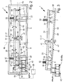
- valve housing 2 which defines a valve chamber 3.
- valve chamber 3 the functional components of the valve 1 are housed.
- the valve housing 2 has a dash-dotted line indicated main axis 4a and a perpendicular transverse axis 4b.
- the illustrated sections extend in a plane spanned by the main axis 4a and the transverse axis 4b.
- the first valve channel 6 opens with a first channel opening 12 in the valve chamber 3, as well as the second valve channel 7 with a second channel mouth 13.
- the first channel mouth 12 is framed by a first valve seat 15, the second channel mouth 13 of a second valve seat 16.
- the valve seats 15, 16 respectively at the free end face of a arranged on the first wall 5 and projecting into the valve chamber 3 elevation 10, 11. This can be formed tapered in particular tapered to the associated valve seat 15, 16 out.
- valve channels 6, 7 open towards the outer surface of the first wall 5. There can be connected away from the valve 1 leading fluid lines, which are not shown.
- the first valve channel 6 is in particular a feed channel and can be connected to an external pressure source, which supplies a fluidic pressure medium, in particular compressed air.
- the second valve channel 7 is expediently a drainage channel which can be connected to a pressure sink, for example to the atmosphere or to a tank. The functionality of the two valve channels 6, 7 can also be reversed.
- the two channel openings 12, 13 with their associated valve seats 15, 16 are arranged expediently spaced from one another in the axial direction of the main axis 4 a. Preferably, however, they lie together in the plane spanned by the main axis 4a and the transverse axis 4b or in a plane parallel thereto.
- the valve seats 15, 16 are preferably aligned identically with respect to one another; they point in the axial direction of the transverse axis 4b and in this case in particular away from the first wall 5.
- a transverse offset of the valve seats 15, 16 at right angles to the aforementioned plane would also be possible in principle.
- a third valve channel 8 also opens into the valve chamber 3. He also expediently passes through the first wall 5. It is in particular a connectable with a consumer to be operated working channel.
- first control element 23 In the valve chamber 3 are a first control element 23 and a respect to the first control element 23 in particular separately formed second control element 24.
- the two controls 23, 24 are independent of each other relative to each other and relative to the valve housing 2 movable.
- a lamellar shaping has proven to be particularly useful for the two controls 23, 24.
- their longitudinal axes extend in particular parallel to the main axis 4a, their main expansion planes being perpendicular to the plane defined by the main axis 4a, the transverse axis 4b, referred to hereinafter as the "reference plane".
- the two controls 23, 24 are arranged alongside each other at a distance. They extend in the starting position with measured in the axial direction of the transverse axis 4b distance next to each other.
- the two control elements 23, 24 are arranged successively in their longitudinal direction, their longitudinal axes aligned with the main axis 4a preferably being aligned coaxially.
- the main planes of extension of both control elements 23, 24 oriented at right angles to the reference plane expediently coincide in the starting position.
- the first control element 23 extends over the first valve seat 15. In the same way, the second control element 24 extends beyond the second valve seat 16.
- Both controls 23, 24 are pivotable with respect to the valve housing 2.
- the pivot plane is parallel to the reference plane, the associated pivot axis 14 extends perpendicular to the reference plane.
- the possible pivoting movement is in FIGS. 1 . 2 and 5 at 28 indicated by a double arrow.
- the pivoting mobility of the control elements 23, 24 is made possible in each case by a pivot bearing 17 arranged between the control element 23, 24 and the valve housing 2.
- a pivot bearing 17 arranged between the control element 23, 24 and the valve housing 2.
- the first control element 23 associated pivot bearing 17 at a first end portion 18 of the first control element 23. In this way, the entire first control member 23 is pivoted in the pivoting movement 28 in either one or the other direction.
- Comparable states apply in the embodiments of FIGS. 2 to 5 for each of the two control elements 23, 24.
- both the first control element 23 and the second control element 24 are each suspended pivotably at a first end region 18 via a pivot bearing 17 relative to the valve housing 2.
- the two control elements 23, 24 are installed with mutually facing first end regions 18, so that the associated pivot bearings 17 can be locally concentrated in the region lying between the two control elements 23, 24 and in particular the possibility exists both Form pivot bearing 17 as a unit.
- the bearing design is such that the two control elements 23, 24 can be pivoted independently of each other according to the double arrow 28 without mutual interference.
- At least one pivot bearing 17 may be formed, for example, as an elastic spring joint, preferably consisting of a resiliently flexible material portion.
- the pivot bearing 17 without cohesive material composite easily formed by relatively movable separate components, for example by means of a bearing shaft or by means of a cutting edge bearing, in which the first end portion 18 is pressed by spring means to a bearing blade.
- the two control elements 23, 24 have in particular the same basic structure and the same basic storage measure is in the embodiment of FIG. 1 formed the second control 24 rocker-like.
- the second control element 24 is generally rigid, with its pivot bearing 17 is located at a location spaced from both end region, such that the second control element 24 is divided by the pivot bearing 17 in a first and second rocker arm 20, 21.
- the pivoting movement according to double arrow 28 manifests itself here in a tilting of the entire second control element 24 about its associated pivot bearing 17th
- the controls 23, 24 could be mounted in a different manner with respect to the valve housing 2 in order to achieve the desired pivoting mobility 28.
- the first control element 23 is provided with a first closure means 36 in the region opposite the first valve seat 15.
- the second control element 24 has a second closure means 37 in the region opposite the second valve seat 16.
- the closure means 36, 37 consist, for example, of a respective plate formed of material with rubber-elastic properties, which is adhered to the associated control element 23, 24 attached there in a different way. It can be too to act a coating of the control element 23, 24.
- the closure means 36, 37 are formed directly by the control element 23, 24.
- each control 23, 24 takes one out FIGS. 1 . 2 and 5 apparent starting position, which is a closed position in all embodiments in which the associated closure means 36, 37 rests with sealing on the valve seat 15, 16 facing it.
- the closed position is expediently predetermined by spring means 32, in particular consisting of at least one leaf spring arrangement or a helical spring arrangement which is effective between the valve housing 2 and the associated first or second control element 23, 24. If the pivotal mounting of a control element 23, 24 by means of a resilient joint, this can also be used for the realization of the spring means, so that could be dispensed with additional separate spring means.
- each control element 23, 24 can only be pivoted in a direction designated below as the opening direction 41. A movement in the opposite direction is prevented by the associated, acting as a stop means valve seat 15, 16.
- each control element 23, 24 By pivoting in the opening direction 41, wherein the restoring force of the spring means 32 is overcome, each control element 23, 24 can be moved to an open position in which the closing means 36 or 37 arranged on it are lifted more or less far from the opposite valve seat 15 or 16 is. There is then a fluidic connection between the open valve channel 6 or 7 and the valve chamber 3, wherein the valve chamber 3 in turn is fluidically connected to the third valve channel 8.
- both control elements 23, 24 occupy the closed position at the same time, the third valve channel 8 (working channel) is separated from both the first and the second valve channels 6, 7 and the volume of fluid possibly supplied beforehand is locked up.
- first control element 23 and simultaneously located in the closed position second control element 24 of the third valve channel 8 is shut off from the second valve channel 7 and connected to the supply of fluid to the first valve channel 6.
- second control element 24 assumes an open position and, at the same time, the first control element 23 is in the closed position, there is a connection between the third valve channel 8 and the second valve channel 7, so that the third valve channel 8 (working channel) is depressurized or vented ,
- the valve 1 can be used to control any fluid, but is preferably used to control compressed air.
- the valve 1 is equipped with electrically activatable drive means in the form of at least one electrodynamic drive device 42.
- the valve according to FIGS. 1 to 4 has just such an electro-dynamic drive device 42, the valve according to FIG. 5 is equipped with two pieces of it.
- Each drive device 42 is able to actuate both the first control element 23 and the second control element 24, that is to perform an optional actuation of each control element 23, 24.
- the drive device 42 is an electrodynamic magnet coil system, as it often comes in speakers, inter alia, used.
- the drive device 42 is configured to have two interacting first and second drive units 43, 44, of which in the embodiment, the first drive unit 43 as a permanent magnet unit 43a and the second drive unit 44 is formed as an electrically energizable coil unit 44a.
- a swapped training would also be possible.
- the two drive units 43, 44 are movable in a conventional manner relative to each other, wherein the driving force is caused by an electric current, with which the coil unit 44a is fed and generates a magnetic field interacting with the magnetic field of the permanent magnet unit 43a.
- the driving force is caused by an electric current, with which the coil unit 44a is fed and generates a magnetic field interacting with the magnetic field of the permanent magnet unit 43a.
- the abovementioned relative movement only manifests itself in a movement of the second drive unit 44.
- first drive unit 43 is stationary with respect to the valve housing 2, it is
- second drive unit 44 is part of a generally designated by reference numeral 45 driver, which is relative to the valve housing 2 and consequently also relative to the first drive unit 43 movable.
- the driver 45 is in particular designed so that it is pivotable relative to the valve housing 2. Its possible pivoting movement is indicated at 46 by a double arrow. Ensures the pivoting movement by a pivot bearing 47, which can be formed in the same manner as the various above with reference to the pivot bearing 17 of the controls 23, 24 embodiments explained.
- the pivot axis defined by the pivot bearing 47 extends parallel to the pivot axes 14 of the controls 23, 24th
- the two drive units 43, 44 are arranged so that they face each other in the direction of pivotal movement 46. Depending on the activation state of the coil unit 44a, they dive into each other more or less widely.
- the structure corresponds in particular to a so-called plunger coil principle, wherein the coil unit 44 can dive more or less far into the permanent magnet unit 43.
- the driver 45 has a preferably rigid, the second drive unit 44 supporting driver arm 48.
- the driver arm 48 is arranged between the two control elements 23, 24, wherein one end region cooperates with the pivot bearing 47 and its other end region is provided with the second drive unit 44.
- the pivot bearing 47 is designed in particular as a spring joint.
- the second arm portion 63 carries no drive unit.
- two drive means 42 can according to FIG. 5 two arm portions 62, 63 each be associated with the drive means 42, so that here each arm portion 62, 63 carries a second drive unit 44.
- the valve 1 may be equipped with a dashed line indicated electrical or electronic control device 58 or connectable. From the coil unit 44a go only in FIGS. 1 and 2 indicated electrical conductors 57 from which are led out of the valve housing 2 and to the outside of the valve housing 2 arranged connecting means 59 lead, to which the control device 58 can be connected.
- the electrical conductors 57 may be at least partially flexible so as not to hinder the movement of the coil unit 44. You can also be guided over the driver arm 48 and associated with this pivot bearing 47 away.
- the coil unit 44a can be energized in two opposite directions.
- the current flow is thus reversible in its direction. This makes it possible to vary the force effect between the two drive units 43, 44.
- the two drive units 43, 44 attract, at the other Bestromungs therapies they repel.
- the driver 45 can be driven, starting from a basic position assumed when the coil unit 44a is de-energized, to either a first working movement 64 or an opposite second working movement 65.
- the exemplary embodiment is the pivoting movement 46 that is executed in one direction or the other.
- the drive principle of the electrodynamic drive device 42 is based on the fact that the current flowing in the coil unit 44a at right angles to the magnetic field of the permanent magnet unit 43a causes a drive force perpendicular to the current direction and the field line direction, the direction of which depends on the current flow direction.
- the direction of the driving force can be reversed to produce either the first working movement 64 or the second working movement 65.
- the current intensity can expediently be set variably.
- the distance or the stroke of the two working movements 64, 65 can specify variable.
- the hub is responsible for each occupied open position of the controls 23, 24 and Consequently, for the released in the open position flow cross-section.
- the driver 45 takes the FIGS. 1 . 2 and 5 apparent basic position.
- the coil unit 44a is expediently in the region of the highest flux density of the permanent magnet unit 43a.
- the basic position is predetermined by the cooperation of spring means which fix the driver 45 in a yielding manner.
- spring means may be present separately and / or integrated into the associated pivot bearing 47.
- the basic position of the driver 45 can also be defined solely by the two controls 43, 44, between which he is interposed operatively. Since the two controls 23, 24 are biased by spring means 32 in its closed position, the driver 45 can be inserted therebetween so that it is in the direction of the first working movement 64 on the first control element 23 and in the direction of the second working movement 65 on the second control 24 supported.
- the abovementioned support is expediently play-related, so that an air gap 66 is present between one or both control elements 23, 24 engaging the closed position and the driver 45 located in the basic position. In this way, a reliable simultaneous closed position of both controls 23, 24 can be ensured in a simple manner.
- the driver 45 transmits the drive force generated by the drive device 42 to either the first or second control element 23, 24.
- the driver 45 in the execution of the first working movement 64, a control force on only the first control element 23 and at Execution of the second working movement 65 exerts a force exclusively on the second control 24. From the other control element 24, 23 of the driver 45 is decoupled in this case drivingly. If one of the controls 23, 24 is moved into an open position, consequently, the respective other control element 24, 23 remains in the closed position.
- This automatically decoupling drive connection is in particular realized in that the driver 45 only by loose contact with the two control elements 23, 24 cooperates, in such a way that it in each case only one of its possible drive movements 64, 65 a force on the controls 23, 24 exercise.
- the valves 1 of the embodiment are designed so that the driver 48 can act on each control element 23, 24 exclusively with a pressing force. Depending on the activation direction, either the first control element 23 or the second control element 24 is actively acted upon in the opening direction 41 by this pressing force.
- a first control element 23 facing first pressing surface 67 and a second control element 24 facing the second pressing surface 68 is arranged, wherein the first pressing surface 67 a arranged on the first control element 23 first actuating surface 72 and the second pressing surface 68 is disposed opposite to a second control element 24 second actuating surface 73.
- the two pressing surfaces 67, 68 are in the embodiment of the FIG. 1 the two pressing surfaces 67, 68 on opposite sides of the driver 45 and have in opposite directions.
- the first pressing surface 67 is preferably arranged in the region of the second drive unit 44, the second pressing surface 68 is expediently located between the section of the driver 45 having the first pressing surface 67 and the pivot bearing 67.
- the driver 45 acts on the first actuating surface 72 with its first pressing surface 67, wherein at the same time the second pressing surface 68 moves away from the second actuating surface 73.
- the second actuating surface 73 and the closure means 37 move in opposite directions relative to the axial direction of the transverse axis 4b due to the rocker characteristic. This reversal of movement makes it possible to arrange the two valve seats 15, 16 with the same orientation.
- the first pressing surface 67 on the first arm portion 62 and the second pressing surface 68 on the second arm portion 63 of the Mit supportivearmes 48 are located on one and the same longitudinal side of the driver 45 and point in the same direction as the valve seats 15, 16. Je according to the direction of pivoting of the driver 45 presses here in each case an arm portion 62 or 63 on the one control element 23, 24, while the other arm portion is removed from the associated control.
- driver 45 is formed rocker-like, it is advantageous if its pivot bearing 47 is located with respect to the axial direction of the main axis 4a at least substantially the same height with the pivot bearings 17 for the controls 23, 24.
- the permanent magnet unit 43a conveniently includes a permanent magnet ring 49 having its longitudinal axis in or parallel to the reference plane and flanked by a front (52) and a rear (53) ferrite pole disc at its two faces.
- the rear pole disk 53 can be used for fastening and carries a central iron core 54, which protrudes coaxially with radial distance in the permanent magnet ring 49.
- the coil unit 44a facing the front pole plate 52 is annular and has a central opening into which the iron core 54 protrudes at a radial distance.
- the iron core 54 and on the other hand, the permanent magnet ring 49 and the front pole plate 52 defines an annular gap 55 which is open to the coil unit 44.
- the coil unit 44a designed as a structural unit with the driver arm 48 contains a coil 55, which is provided with a suitable number of windings and which is arranged substantially coaxially with the permanent magnet unit 43a. Its rear end face is facing the Mit Conversearm 48, its free front end faces the permanent magnet unit 43 a. With this front free front side, the coil 56 immersed in the aforementioned annular gap 55 a. The immersion depth depends on the intensity and direction of the energization of the coil 56.
- both controls 23, 24 are each in the form of a one-armed lever, while the rocker-like driver 45 is designed as a two-armed lever.
Description
Die Erfindung betrifft ein Ventil, mit zwei in einem Ventilgehäuse relativ zu diesem und relativ zueinander zwischen jeweils einer Schließstellung und mindestens einer Offenstellung bewegbar angeordneten ersten und zweiten Steuerelementen, von denen das erste Steuerelement mit einem einem ersten Ventilsitz zugeordneten ersten Verschlussmittel und das zweite Steuerelement mit einem einem zweiten Venilsitz zugeordneten zweiten Verschlussmittel bewegungsgekoppelt ist, wobei jedes Verschlussmittel in der Schließstellung des mit ihm bewegungsgekoppelten Steuerelementes dichtend am zugeordneten Ventilsitz anliegt und in der Offenstellung davon abgehoben ist, und mit elektrisch aktivierbaren Antriebsmitteln zum Betätigen der Steuerelemente, wobei die Antriebsmittel von mindestens einer die wahlweise Betätigung jedes Steuerelementes ermöglichenden elektrodynamischen Antriebseinrichtung gebildet sind, die zwei miteinander kooperierende und relativ zueinander bewegliche erste und zweite Antriebseinheiten in Form einer Permanentmagneteinheit und einer elektrisch bestrombaren Spuleneinheit enthält, wobei die erste Antriebseinheit ortsfest bezüglich dem Ventilgehäuse angeordnet und die zweite Antriebseinheit Bestandteil eines relativ zum Ventilgehäuse beweglichen Mitnehmers ist.The invention relates to a valve, with two in a valve housing relative to this and relative to each other between each closed position and at least one open position movably arranged first and second controls, of which the first control with a first valve seat associated first closure means and the second control with a second closure means associated with a second valve seat is coupled for movement, wherein each closure means sealingly abuts in the closed position of the motion-coupled with him control element on the associated valve seat and is lifted off in the open position thereof, and with electrically activatable drive means for actuating the controls, wherein the drive means of at least one the selective actuation of each control element enabling electrodynamic drive means are formed, the two cooperating with each other and relatively movable first and second An drive unit in the form of a permanent magnet unit and an electrically energized coil unit, wherein the first drive unit arranged stationary relative to the valve housing and the second drive unit is part of a relative to the valve housing movable carrier.
Ein Ventil in Form eines Piezoventils ist aus der
Aus der
Aus der
Aus der
Die
In der erst nach dem Prioritätsdatum der vorliegenden Patentanmeldung veröffentlichten
Es ist die Aufgabe der vorliegenden Erfindung, ein zur Steuerung zweier Ventilkanäle geeignetes Ventil zu schaffen, das bei einfacher und kostengünstiger Herstellung eine lange Lebensdauer verspricht.It is the object of the present invention to provide a suitable valve for controlling two valve passages, which promises a long life with simple and cost-effective production.
Zur Lösung dieser Aufgabe ist erfindungsgemäß vorgesehen, dass der Mitnehmer ausgehend von einer bei unbestromter Spuleneinheit vorliegenden Grundstellung je nach gewählter Richtung der Bestromung der Spuleneinheit zu wahlweise einer von zwei einander entgegengesetzt orientierten ersten und zweiten Arbeitsbewegungen antreibbar ist, bei deren Ausführung er bei gleichzeitiger antriebsmäßiger Entkopplung vom jeweils anderen Steuerelement auf entweder das erste oder das zweite Steuerelement einwirkt, um dessen Schaltstellung zu verändern.To achieve this object, the invention provides that the driver, starting from a present at no current coil unit basic position depending on the selected direction of energization of the coil unit to either one of two oppositely oriented first and second working movements can be driven in the execution of he simultaneous driving decoupling from each other control acts on either the first or the second control to change its switching position.
Somit genügt prinzipiell eine einzige elektrodynamische Antriebseinrichtung, um entweder das eine oder das andere Steuerelement zu betätigen und in einer gewünschten Schaltstellung zu positionieren. Die Antriebseinrichtung ist den beiden Steuerelementen funktionell gemeinsam zugeordnet, wobei eine ihrer Antriebseinheiten, also entweder die Permanentmagneteinheit oder die Spuleneinheit, ortsfest bezüglich des Ventilgehäuses angeordnet ist und die relative Beweglichkeit zwischen den beiden Antriebseinheiten nur durch die Bewegung der bezüglich dem Ventilgehäuse nicht ortsfesten Antriebseinheit realisiert wird, die als Bestandteil eines relativ zum Ventilgehäuse beweglichen Mitnehmers ausgebildet ist. Durch Bestromung der Spuleneinheit kann somit der Mitnehmer abhängig von der Bestromungsrichtung zu einer ersten Arbeitsbewegung oder zu einer diesbezüglich entgegengesetzt orientierten zweiten Arbeitsbewegung angetrieben werden, wobei er entweder nur auf das eine oder nur auf das andere Steuerelement eine dieses umschaltende Antriebskraft ausübt, während er vom jeweils anderen Steuerelement antriebsmäßig entkoppelt ist, so dass dieses seine momentane Schaltstellung beibehalten kann. Somit liegt eine äußerst kompakte Anordnung vor, die wenig verschleißanfällig ist und nur geringe Ansteuerspannungen erfordert. Die Herstellung lässt sich verhältnismäßig kostengünstig bewerkstelligen. Außerdem wird das Betriebsverhalten des Ventils durch Schwankungen in der Umgebungstemperatur und durch Feuchtigkeitseinflüsse kaum beeinträchtigt.Thus, in principle, a single electrodynamic drive device is sufficient to operate either one or the other control and to position in a desired switching position. The drive device is functionally assigned to the two control elements together, one of their drive units, so either the permanent magnet unit or the coil unit, is stationary with respect to the valve housing and the relative mobility between the two drive units only by the movement of the is realized with respect to the valve housing not fixed drive unit, which is formed as part of a relative to the valve housing movable carrier. By energizing the coil unit thus the driver can be driven depending on the Bestromungsrichtung to a first working movement or to a related oppositely oriented second working movement, where he either only on one or only on the other control exerts this switching driving force, while he from each another control is drivingly decoupled, so that this can maintain its current switching position. Thus, there is an extremely compact arrangement, which is less susceptible to wear and requires only low drive voltages. The production can be accomplished relatively inexpensively. In addition, the operating behavior of the valve is hardly affected by fluctuations in the ambient temperature and by the effects of moisture.
Zweckmäßigerweise besteht die Möglichkeit, durch Veränderung der Stromstärke bei der elektrischen Ansteuerung der Spuleneinheit das Maß der im Rahmen der jeweiligen Arbeitsbewegung erzielbaren Auslenkung des Mitnehmers und mithin auch der Steuerelemente zwischen Maximalwerten zu variieren, insbesondere stufenlos. Auf diese Weise kann insbesondere die Möglichkeit geschaffen werden, ein und dasselbe Steuerelement in verschiedenen Offenstellungen zu positionieren, in denen das ihm zugeordnete Verschlussmittel unterschiedlich weit von dem ihm gegenüberliegenden Ventilsitz abgehoben ist und es folglich einen unterschiedlich großen Strömungsquerschnitt freigeben kann. Dies ermöglicht einen besonders vorteilhaften Betrieb des Ventils als Proportionalventil.Appropriately, it is possible to vary by varying the current in the electrical control of the coil unit, the extent of achievable in the context of the respective working movement deflection of the driver and thus also the controls between maximum values, in particular continuously. In this way, in particular the possibility can be created to position one and the same control element in different open positions, in which the closure means assigned to it is lifted at different distances from the valve seat opposite it and consequently it can release a flow cross section of different sizes. This allows a particularly advantageous operation of the valve as a proportional valve.
Zweckmäßigerweise ist die Permanentmagneteinheit konstruktiv so ausgelegt, dass sich an einer bevorzugten Stelle die höchste Flussdichte des Magneten einstellt. Zweckmäßigerweise in diesem Bereich liegt die Spuleneinheit, wenn der Mitnehmer die Grundstellung einnimmt. Zur Fixierung in der Grundstellung kann der Mitnehmer über beispielsweise ein elastisches Gelenk oder sonstige nachgiebige Aufhängungsmittel bezüglich dem Ventilgehäuse fixiert sein.Conveniently, the permanent magnet unit is structurally designed so that adjusts the highest flux density of the magnet at a preferred location. Appropriately, in this area is the coil unit when the driver assumes the basic position. For fixation in the basic position of the driver may be fixed over, for example, an elastic joint or other resilient suspension means with respect to the valve housing.
Vorteilhafte Weiterbildungen der Erfindung gehen aus den Unteransprüchen hervor.Advantageous developments of the invention will become apparent from the dependent claims.
Besonders kompakte Abmessungen sind realisierbar, wenn die beiden Antriebseinheiten so ausgebildet sind, dass sie in Abhängigkeit von ihrer Relativposition mehr oder weniger weit ineinander eintauchen. Hierbei kommt insbesondere ein Tauchspulenprinzip zur Anwendung, bei dem die Spuleneinheit mehr oder weniger weit in die Permanentmagneteinheit eintaucht, insbesondere in koaxialer Anordnung.Particularly compact dimensions can be realized if the two drive units are designed such that they dive into each other more or less depending on their relative position. In this case, in particular, a submersible coil principle is used, in which the coil unit is more or less immersed in the permanent magnet unit, in particular in a coaxial arrangement.
Zur Vorgabe der Bestromungsrichtung der Spuleneinheit ist zweckmäßigerweise eine geeignete Steuereinrichtung vorhanden. Mit ihr lässt sich vorzugsweise auch die Dauer der Bestromung und folglich die Dauer der Einhaltung der jeweils gewünschten Ventilstellung kontrollieren. Ist die Steuereinrichtung auch zur variablen Vorgabe der Bestomungsintensität ausgebildet, lässt sich nicht nur ein rein digitales Schaltverhalten der Steuerelemente realisieren, sondern bei Bedarf eine proportionale Betriebsweise, bei der die Auslenkung der Steuerelemente proportional zur Stromstärke regulierbar ist.To specify the Bestromungsrichtung the coil unit expediently a suitable control device is present. With her can be preferably also control the duration of the energization and consequently the duration of compliance with the particular desired valve position. If the control device is also designed for the variable specification of the intensity of the charge, not only a purely digital switching behavior of the control elements can be realized but, if required, a proportional mode of operation in which the deflection of the control elements can be regulated in proportion to the current intensity.
Da die Masse einer Spuleneinheit in der Regel kleiner ist als diejenige einer Permanentmagneteinheit, ist es zur Minimierung der zu bewegenden Massen vorteilhaft, die Permanentmagneteinheit ortsfest am Ventilgehäuse anzuordnen und die Spuleneinheit als Bestandteil des Mitnehmers auszuführen.Since the mass of a coil unit is usually smaller than that of a permanent magnet unit, it is for minimization the masses to be moved advantageous to arrange the permanent magnet unit stationary on the valve housing and to perform the coil unit as part of the driver.
Bei einer zweckmäßigen Ausgestaltung der Ventileinheit sind die Verschlussmittel und die Ventilsitze so angeordnet, dass beide Steuerelemente ihre Schließstellung einnehmen, wenn der Mitnehmer aufgrund unbestromter Spuleneinheit seine Grundstellung einnimmt. Die Schließstellung der Steuerelemente wird insbesondere durch Federmittel in nachgiebiger Weise vorgegeben, so dass der Mitnehmer die zugeordnete Federkraft überwinden muss, um ein Steuerelement in eine Offenstellung auszulenken. Das momentan vom Mitnehmer nicht beeinflusste Steuerelement verbleibt dann in durch die Federmittel vorgespannter Weise in der Schließstellung. Die Federmittel sind zweckmäßigerweise mechanischer Art und können platzsparend von mindestens einer Blattfeder gebildet sein oder auch durch eine interne Federelastizität der Steuerelemente selbst realisiert sein.In an expedient embodiment of the valve unit, the closure means and the valve seats are arranged so that both control elements assume their closed position when the driver assumes its basic position due to the current coil unit without current. The closed position of the controls is particularly given by spring means in a yielding manner, so that the driver has to overcome the associated spring force to deflect a control in an open position. The currently not affected by the driver control then remains biased by the spring means in the closed position. The spring means are suitably of a mechanical nature and may be formed to save space by at least one leaf spring or be implemented by an internal spring elasticity of the controls themselves.
Die Ventilsitze umschließen zweckmäßigerweise jeweils einen in eine Ventilkammer des Ventils einmündenden eigenen Ventilkanal, von denen der eine zweckmäßigerweise ein der Zufuhr eines Druckmediums dienender Speisekanal und der andere ein zur Druckentlastung dienender, bei pneumatischen Anwendungen als Entlüftungskanal fungierender Abführkanal ist. Zusätzlich zu diesen beiden steuerbaren Ventilkanälen mündet zweckmäßigerweise noch mindestens ein weiterer, dritter Ventilkanal in die Ventilkammer ein, der ständig offen ist und dessen Strömungsquerschnitt durch die Steuerelemente nicht beeinflussbar ist. Bei ihm handelt es sich zweckmäßigerweise um einen mit einem anzusteuernden Verbraucher verbindbaren Arbeitskanal. Somit kann beispielsweise ein 3/3-Wegeventil realisiert werden, insbesondere in einer Ausgestaltung als Proportionalventil. Die Verschlussmittel sind zweckmäßigerweise unmittelbar am jeweils zugeordneten Steuerelement angeordnet. Es kann sich bei ihnen um aus Material mit abdichtenden Eigenschaften bestehende Dichtungselemente handeln, die angeklebt oder auf sonstige Weise fixiert sind. Es ist aber auch möglich, die Steuerelemente so auszubilden, dass sie unmittelbar selbst die Verschlussmittel definieren.The valve seats expediently in each case surround a separate valve channel opening into a valve chamber of the valve, one of which expediently being a feed channel serving to supply a pressure medium and the other being a discharge channel serving as a vent for pneumatical applications. In addition to these two controllable valve channels, at least one further, third valve channel expediently also opens into the valve chamber, which is constantly open and whose flow cross-section can not be influenced by the control elements. It is expediently a working channel which can be connected to a consumer to be activated. Thus, for example, a 3/3-way valve can be realized, in particular in one embodiment as a proportional valve. The closure means are expediently arranged directly on the respectively associated control element. They may be sealing materials made of material with sealing properties that are glued or otherwise fixed. However, it is also possible to design the control elements in such a way that they themselves directly define the closure means.
Die Antriebsverbindung zwischen dem Mitnehmer und jedem Steuerelement ist zweckmäßigerweise eine nur lose Verbindung, wobei der Mitnehmer zur Übertragung einer ein Steuerelement auslenkenden Stellkraft ohne feste Verbindung in insbesondere drückender Weise auf das betreffende Steuerelement einwirkt. Abweichend hiervon wäre prinzipiell auch eine Bauform denkbar, bei der nur eine ziehende Kraft ausgeübt werden kann. Konstruktiv einfacher lässt sich jedoch eine zur ausschließlichen Übertragung von drückenden Kräften geeignete antriebsmäßige Kopplung verwirklichen.The drive connection between the driver and each control is expediently only a loose connection, wherein the driver for transmitting a control deflecting force without firm connection in particular oppressive manner acts on the relevant control. Notwithstanding this, in principle, a design would be conceivable in which only a pulling force can be exercised. However, a drive coupling suitable for the exclusive transmission of compressive forces can be realized in a structurally simpler manner.
Um solche Drückkräfte übertragen zu können, verfügt der Mitnehmer zweckmäßigerweise über je mindestens eine erste und zweite Drückfläche, der jeweils eine am jeweils zugeordneten Steuerelement angeordnete erste bzw. zweite Betätigungsfläche gegenüberliegt. Je nach Bewegungsrichtung wirkt dann der Mitnehmer mit der einen Drückfläche auf die eine Betätigungsfläche ein, während sich gleichzeitig seine andere Drückfläche von der Betätigungsfläche des anderen, in der Ausgangsstellung verharrenden Steuerelementes entfernt.In order to be able to transmit such pressing forces, the driver expediently has at least one first and second pressing surface each opposite a first or second actuating surface arranged on the respective associated control element. Depending on the direction of movement of the driver then acts with the one pressing surface on the one actuating surface, while at the same time removes its other pressing surface of the actuating surface of the other, remaining in the starting position control.
Die Auslegung der einzelnen Komponenten ist insbesondere so getroffen, dass in der Grundstellung des Mitnehmers zwischen mindestens einer und unsbesondere jeder Drückfläche und der dieser gegenüberliegenden Betätigungsfläche ein kleiner Luftspalt vorliegt, so dass Überbestimmungen vermieden werden und eine zuverlässige gleichzeitige Einnahme der Schließstellung durch beide Steuerelemente gewährleistet werden kann.The design of the individual components is particularly such that in the basic position of the driver between at least one and unspecific each pressing surface and this opposite actuating surface a smaller Air gap is present so that over-determination can be avoided and a reliable simultaneous taking the closed position can be ensured by both controls.
Je nach Ausgestaltung und Lagerung des Mitnehmers können sich die beiden Drückflächen an einander entgegengesetzten Seiten oder an ein und derselben Seite des Mitnehmers befinden. Die erstgenannte Variante wird insbesondere dann gewählt, wenn der Mitnehmer zwischen die beiden Betätigungsflächen ragt und insbesondere auf einander entgegengesetzten Seiten von den beiden Steuerelementen flankiert wird. Die an zweiter Stelle genannte Variante kommt insbesondere dann zum Einsatz, wenn die beiden Betätigungsflächen und insbesondere auch beide Steuerelemente auf der gleichen Seite des Mitnehmers platziert sind und der Mitnehmer wippenartig ausgebildet ist, wobei seine Drückflächen beidseits seines Schwenklagers platziert sind.Depending on the design and storage of the driver, the two pressing surfaces may be located on opposite sides or on one and the same side of the driver. The former variant is chosen in particular when the driver protrudes between the two actuating surfaces and is flanked in particular on opposite sides of the two control elements. The second named variant is used in particular when the two actuating surfaces and in particular both controls are placed on the same side of the driver and the driver is formed like a rocker, with its pressing surfaces are placed on both sides of its pivot bearing.
Beide Steuerelemente sind zweckmäßigerweise derart ausgebildet, dass ihre Steuerbewegung eine Schwenkbewegung ist. Insbesondere wenn die zu steuernden Ventilsitze untereinander identisch ausgerichtet sind, ist es empfehlenswert, eines der Steuerelemente zur Realisierung einer Richtungsumkehr der Bewegung des Verschlussmittels wippenartig auszubilden.Both controls are suitably designed such that their control movement is a pivoting movement. In particular, if the valve seats to be controlled are aligned identically to one another, it is advisable to design one of the control elements in order to realize a reversal of direction of the movement of the closure means like a rocker.
Insbesondere in Verbindung mit einem wippenartig ausgebildeten Mitnehmer ist es zur Vermeidung unerwünschter Schwingungen zweckmäßig, jedem Mitnehmerarm eine eigene elektrodynamische Antriebseinrichtung zuzuordnen, so dass auf einfache Weise ein Massenausgleich realisierbar ist.In particular, in conjunction with a rocker-like driver, it is expedient to avoid unwanted vibrations, assign each driver own electrodynamic drive means, so that in a simple way, a mass balance can be realized.
Es sei auch noch auf die Möglichkeit verwiesen, im Bereich jeder Antriebseinrichtung ein sogenanntes Ferrofluid zu platzieren. Hierbei handelt es sich um eine Flüssigkeit, die auf ein magnetisches Feld reagiert. Sie befindet sich dort, wo ansonsten ein Luftspalt um die Spuleneinheit herum angeordnet wäre und wird durch das Feld der Permanentmagneteinheit gehalten. Das Ferrofluid bewirkt unter anderem eine Kühlung der Spuleneinheit sowie eine Dämpfung der sich bewegenden Komponenten.It should also be made to the possibility to place a so-called ferrofluid in the area of each drive means. This is a liquid on a magnetic field reacts. It is located where otherwise an air gap would be arranged around the coil unit and is held by the field of the permanent magnet unit. Among other things, the ferrofluid effects cooling of the coil unit and damping of the moving components.
Nachfolgend wird die Erfindung anhand der beiliegenden Zeichnung näher erläutert. In dieser zeigen:
- Figur 1
- eine bevorzugte erste Bauform des erfindungsgemäßen Ventils in einer schematischen Schnittdarstellung, wobei der Mitnehmer in der Grundstellung und die beiden Steuerelemente in jeweils ihrer Schließstellung gezeigt sind,
Figur 2- einen schematischen Längsschnitt durch ein weiteres Ausführungsbeispiel des erfindungsgemäßen Ventils, wobei wiederum der Mitnehmer bei Einnahme der deaktivierten Grundstellung und beide Steuerelemente bei Einnahme ihrer Schließstellung gezeigt sind,
Figur 3- funktionell relevante Komponenten des Ventils aus
Figur 2 in der Offenstellung des einen Steuerelementes, - Figur 4
- das
Ventil aus Figur 2 ineiner mit Figur 3 übereinstimmenden Darstellungsweise, jedoch bei Einnahme der Offenstellung durch das andere Steuerelement, und Figur 5- einen schematischen Längsschnitt durch eine weitere Ausführungsform des Ventils, wobei wie in
Figuren 34 das Ventilgehäuse nicht gezeigt ist und wobei der Mitnehmer die Grundstellung und die beiden Steuerelemente jeweils ihre Schließstellung einnehmen.
- FIG. 1
- a preferred first design of the valve according to the invention in a schematic sectional view, wherein the driver in the normal position and the two control elements are shown in each case in its closed position,
- FIG. 2
- a schematic longitudinal section through a further embodiment of the valve according to the invention, again showing the driver when taking the deactivated basic position and both controls when taking their closed position,
- FIG. 3
- functionally relevant components of the valve
FIG. 2 in the open position of the one control element, - FIG. 4
- the valve off
FIG. 2 in one withFIG. 3 consistent presentation, but taking the open position by the other control, and - FIG. 5
- a schematic longitudinal section through a further embodiment of the valve, wherein as in
Figures 3 and4 the valve housing is not shown and wherein the Carrier the basic position and the two controls each take their closed position.
Die nachfolgende Beschreibung bezieht sich, sofern im Einzelfall keine andere Aussage getroffen wird, einheitlich auf alle Ausführungsbeispiel.The following description refers, unless otherwise stated in a particular case, uniformly to all embodiments.
Das insgesamt mit Bezugsziffer 1 bezeichnete Ventil enthält ein nur in
Das Ventilgehäuse 2 besitzt eine strichpunktiert angedeutete Hauptachse 4a und eine dazu rechtwinkelige Querachse 4b. Die abgebildeten Schnitte verlaufen in einer durch die Hauptachse 4a und die Querachse 4b aufgespannten Ebene.The
Eine erste Wandung 5 des Ventilgehäuses 2, die beim Ausführungsbeispiels den Boden der Ventilkammer 3 definiert, ist von einem ersten und zweiten Ventilkanal 6, 7 durchsetzt. Der erste Ventilkanal 6 mündet mit einer ersten Kanalmündung 12 in die Ventilkammer 3 ein, ebenso der zweite Ventilkanal 7 mit einer zweiten Kanalmündung 13. Die erste Kanalmündung 12 ist von einem ersten Ventilsitz 15 umrahmt, die zweite Kanalmündung 13 von einem zweiten Ventilsitz 16. Vorzugsweise befinden sich die Ventilsitze 15, 16 jeweils an der freien Stirnseite einer an der ersten Wandung 5 angeordneten und in die Ventilkammer 3 hineinragenden Erhebung 10, 11. Diese kann zum zugeordneten Ventilsitz 15, 16 hin insbesondere konisch verjüngt ausgebildet sein.A
Mit ihren der ersten und zweiten Kanalmündung 12, 13 entgegengesetzten äußeren Kanalmündungen 22 sind die beiden Ventilkanäle 6, 7 zur Außenfläche der ersten Wandung 5 hin offen. Dort können vom Ventil 1 wegführende Fluidleitungen angeschlossen werden, die nicht weiter abgebildet sind.With their first and
Der erste Ventilkanal 6 ist insbesondere ein Speisekanal und kann mit einer externen Druckquelle verbunden werden, die ein fluidisches Druckmedium liefert, insbesondere Druckluft. Der zweite Ventilkanal 7 ist zweckmäßigerweise ein mit einer Drucksenke, beispielsweise mit der Atmosphäre oder mit einem Tank verbindbarer Abführkanal. Die Funktionalität der beiden Ventilkanäle 6, 7 kann auch vertauscht sein.The
Die beiden Kanalmündungen 12, 13 mit ihren zugeordneten Ventilsitzen 15, 16 sind in Achsrichtung der Hauptachse 4a zweckmäßigerweise beabstandet zueinander angeordnet. Bevorzugt liegen sie allerdings gemeinsam in der von der Hauptachse 4a und der Querachse 4b aufgespannten oder einer hierzu parallelen Ebene. Untereinander sind die Ventilsitze 15, 16 bevorzugt identisch ausgerichtet, sie weisen in Achsrichtung der Querachse 4b und hierbei insbesondere von der ersten Wandung 5 weg. Ein Querversatz der Ventilsitze 15, 16 rechtwinkelig zu der vorgenannten Ebene wäre prinzipiell ebenfalls möglich.The two
An einer anderen Stelle mündet ein dritter Ventilkanal 8 ebenfalls in die Ventilkammer 3 ein. Auch er durchsetzt zweckmäßigerweise die erste Wandung 5. Bei ihm handelt es sich insbesondere um einen mit einem zu betätigenden Verbraucher verbindbaren Arbeitskanal.At another point, a
In der Ventilkammer 3 befinden sich ein erstes Steuerelement 23 und ein bezüglich dem ersten Steuerelement 23 insbesondere gesondert ausgebildetes zweites Steuerelement 24. Jedenfalls sind die beiden Steuerelemente 23, 24 unabhängig voneinander relativ zueinander und relativ zum Ventilgehäuse 2 bewegbar. Obgleich prinzipiell auch andere Gestaltungsformen möglich wären, hat sich für die beiden Steuerelemente 23, 24 eine lamellenförmige Formgebung als besonders zweckmäßig erwiesen. Es handelt sich also zweckmäßigerweise um längliche, bevorzugt streifenförmig gestaltete Bauteile, deren Längsachsen bei Einnahme einer Ausgangsstellung parallel zueinander verlaufen, wie dies aus
Bei dem Ausführungsbeispiel der
Bei den Ausführungsbeispielen der
Das erste Steuerelement 23 erstreckt sich über den ersten Ventilsitz 15 hinweg. In gleicher Weise erstreckt sich das zweite Steuerelement 24 über den zweiten Ventilsitz 16 hinweg.The
Beide Steuerelemente 23, 24 sind bezüglich dem Ventilgehäuse 2 verschwenkbar. Die Schwenkebene verläuft parallel zu der Bezugsebene, die jeweils zugeordnete Schwenkachse 14 verläuft rechtwinkelig zu der Bezugsebene. Die mögliche Schwenkbewegung ist in
Die Schwenkbeweglichkeit der Steuerelemente 23, 24 wird jeweils durch ein zwischen dem Steuerelement 23, 24 und dem Ventilgehäuse 2 angeordnetes Schwenklager 17 ermöglicht. Beim Ausführungsbeispiel der
Vergleichbare Zustände gelten bei den Ausführungsbeispielen der
Mindestens ein Schwenklager 17 kann beispielsweise als elastisches Federgelenk ausgebildet sein, vorzugsweise bestehend aus einem federelastisch biegbaren Materialabschnitt. Ebenso besteht jedoch die Möglichkeit, die Schwenklager 17 ohne stoffschlüssigen Materialverbund einfach durch relativ zueinander bewegliche gesonderte Komponenten auszubilden, beispielsweise mittels einer Lagerwelle oder mittels einer Schneidenlagerung, bei der der erste Endbereich 18 durch Federmittel an eine Lagerungsschneide angedrückt wird.At least one pivot bearing 17 may be formed, for example, as an elastic spring joint, preferably consisting of a resiliently flexible material portion. However, it is also possible, the pivot bearing 17 without cohesive material composite easily formed by relatively movable separate components, for example by means of a bearing shaft or by means of a cutting edge bearing, in which the
Während also bei den Ventilen der
Abgesehen von den geschilderten Lagerungsarten könnten die Steuerelemente 23, 24 auch auf andere Weise bezüglich dem Ventilgehäuse 2 gelagert werden, um die gewünschte Schwenkbeweglichkeit 28 zu erreichen.Apart from the described types of storage, the
Bei allen Ausführungsformen ist das erste Steuerelement 23 in dem dem ersten Ventilsitz 15 gegenüberliegenden Bereich mit einem ersten Verschlussmittel 36 versehen. In gleicher Weise verfügt das zweite Steuerelement 24 in dem dem zweiten Ventilsitz 16 gegenüberliegenden Bereich über ein zweites Verschlussmittel 37. Die Verschlussmittel 36, 37 bestehen beispielhaft aus jeweils einem aus Material mit gummielastischen Eigenschaften gebildeten Plättchen, das an das zugeordnete Steuerelement 23, 24 angeklebt oder dort auf andere Weise befestigt ist. Es kann sich aber auch um eine Beschichtung des Steuerelementes 23, 24 handeln. Im einfachsten Fall wird das Verschlussmittel 36, 37 unmittelbar von dem Steuerelement 23, 24 gebildet.In all embodiments, the
Im unbetätigten Zustand nimmt jedes Steuerelement 23, 24 eine aus
Ausgehend von der Ausgangsstellung, vorliegend also der Schließstellung, kann jedes Steuerelement 23, 24 nur in einer im Folgenden als Öffnungsrichtung 41 bezeichneten Richtung verschwenkt werden. Eine Bewegung in entgegengesetzter Richtung ist durch den zugeordneten, als Anschlagmittel fungierenden Ventilsitz 15, 16 verhindert.Starting from the initial position, in the present case therefore the closed position, each
Durch Verschwenken in der Öffnungsrichtung 41, wobei die Rückstellkraft der Federmittel 32 zu überwinden ist, kann jedes Steuerelement 23, 24 in eine Offenstellung bewegt werden, in der das an ihm angeordnete Verschlussmittel 36 oder 37 vom gegenüberliegenden Ventilsitz 15 oder 16 mehr oder weniger weit abgehoben ist. Es liegt dann eine fluidische Verbindung zwischen dem offenen Ventilkanal 6 oder 7 und der Ventilkammer 3 vor, wobei die Ventilkammer 3 ihrerseits mit dem dritten Ventilkanal 8 fluidisch verbunden ist.By pivoting in the
Je nachdem, wie weit ein Steuerelement 23, 24 aus der Schließstellung ausgelenkt wird, ergeben sich Offenstellungen mit unterschiedlich großen freigegebenen Strömungsquerschnitten, da der freigegebene Strömungsquerschnitt davon abhängt, wie weit ein Verschlussmittel 36, 37 vom zugeordneten Ventilsitz 15, 16 abgehoben ist.Depending on how far a
Wenn im Betrieb des Ventils 1 beide Steuerelemente 23, 24 zur gleichen Zeit die Schließstellung einnehmen, ist der dritte Ventilkanal 8 (Arbeitskanal) von sowohl dem ersten als auch dem zweiten Ventilkanal 6, 7 abgetrennt und das ihm zuvor eventuell zugeführte Fluidvolumen ist eingesperrt. Bei in einer Offenstellung befindlichem ersten Steuerelement 23 und gleichzeitig in Schließstellung befindlichem zweiten Steuerelement 24 ist der dritte Ventilkanal 8 vom zweiten Ventilkanal 7 abgesperrt und zur Speisung mit Fluid mit dem ersten Ventilkanal 6 verbunden. Nimmt das zweite Steuerelement 24 eine Offenstellung ein und befindet sich gleichzeitig das erste Steuerelement 23 in der Schließstellung, liegt eine Verbindung zwischen dem dritten Ventilkanal 8 und dem zweiten Ventilkanal 7 vor, so dass der dritte Ventilkanal 8 (Arbeitskanal) druckmäßig entlastet bzw. entlüftet wird.If, during operation of the valve 1, both
Das Ventil 1 lässt sich zur Steuerung jedes beliebigen Fluides einsetzen, wird aber bevorzugt zur Steuerung von Druckluft genutzt.The valve 1 can be used to control any fluid, but is preferably used to control compressed air.
Zur Betätigung der Steuerelemente 23, 24 ist das Ventil 1 mit elektrisch aktivierbaren Antriebsmitteln in Gestalt mindestens einer elektrodynamischen Antriebseinrichtung 42 ausgestattet. Das Ventil gemäß
Jede Antriebseinrichtung 42 ist in der Lage, sowohl das erste Steuerelement 23 als auch das zweite Steuerelement 24 zu betätigen, also eine wahlweise Betätigung jedes Steuerelementes 23, 24 vorzunehmen. Die Antriebseinrichtung 42 ist ein elektrodynamisches Magnet-Spule-System, wie es unter anderem häufig auch in Lautsprechern zur Anwendung gelangt.Each
Genauer gesagt ist die Antriebseinrichtung 42 dahingehend aufgebaut, dass sie zwei miteinander in Wechselwirkung stehende erste und zweite Antriebseinheiten 43, 44 aufweist, von denen beim Ausführungsbeispiel die erste Antriebseinheit 43 als Permanentmagneteinheit 43a und die zweite Antriebseinheit 44 als elektrisch bestrombare Spuleneinheit 44a ausgebildet ist. Eine vertauschte Ausbildung wäre jedoch ebenfalls möglich.More specifically, the
Die beiden Antriebseinheiten 43, 44 sind in an sich bekannter Weise relativ zueinander beweglich, wobei die Antriebskraft durch einen elektrischen Strom verursacht wird, mit dem die Spuleneinheit 44a gespeist wird und der ein mit dem Magnetfeld der Permanentmagneteinheit 43a in Wechselwirkung tretendes Magnetfeld erzeugt. Je nach Bestromungsrichtung ergibt sich eine anziehende oder abstoßende Wirkung der genannten Magnetfelder, aus der eine Relativbewegung zwischen den beiden Antriebseinheiten 43, 44 resultiert.The two
Die vorgenannte Relativbewegung äußert sich bei den beschriebenen Ventilen 1 allerdings lediglich in einer Bewegung der zweiten Antriebseinheit 44. Während die erste Antriebseinheit 43 ortsfest bezüglich dem Ventilgehäuse 2 angeordnet ist - sie ist beispielsweise an der Innenseite des Ventilgehäuses 2 und dabei vorzugsweise an der ersten Wandung 5 befestigt - bildet die zweite Antriebseinheit 44 einen Bestandteil eines insgesamt mit Bezugsziffer 45 bezeichneten Mitnehmers, der relativ zum Ventilgehäuse 2 und folglich auch relativ zu der ersten Antriebseinheit 43 bewegbar ist.However, in the case of the valves 1 described, the abovementioned relative movement only manifests itself in a movement of the
Der Mitnehmer 45 ist insbesondere so ausgebildet, dass er relativ zum Ventilgehäuse 2 verschwenkbar ist. Seine mögliche Schwenkbewegung ist bei 46 durch einen Doppelpfeil angedeutet. Gewährleistet wird die Schwenkbeweglichkeit durch ein Schwenklager 47, das in gleicher Weise ausgebildet werden kann wie die verschiedenen weiter oben anhand des Schwenklagers 17 der Steuerelemente 23, 24 erläuterten Ausführungsformen. Die durch das Schwenklager 47 definierte Schwenkachse verläuft parallel zu den Schwenkachsen 14 der Steuerelemente 23, 24.The
Die beiden Antriebseinheiten 43, 44 sind so angeordnet, dass sie sich in der Richtung der Schwenkbewegung 46 gegenüberliegen. Dabei tauchen sie je nach Aktivierungszustand der Spuleneinheit 44a mehr oder weniger weit ineinander ein. Der Aufbau entspricht insbesondere einem sogenannten Tauchspulenprinzip, wobei die Spuleneinheit 44 mehr oder weniger weit in die Permanentmagneteinheit 43 eintauchen kann.The two
Allen Ausführungsbeispielen ist gemeinsam, dass der Mitnehmer 45 einen bevorzugt starren, die zweite Antriebseinheit 44 tragenden Mitnehmerarm 48 aufweist. Beim Ausführungsbeispiel der
Bei den Ausführungsbeispielen der
Bei dem mit nur einer Antriebsrichtung 42 ausgestatteten Ventil der
Zur gesteuerten Bestromung der Spuleneinheit 44a kann das Ventil 1 mit einer gestrichelt angedeuteten elektrischen oder elektronischen Steuereinrichtung 58 ausgestattet oder verbindbar sein. Von der Spuleneinheit 44a gehen lediglich in
Über die Steuereinrichtung 58 kann die Spuleneinheit 44a in zwei einander entgegengesetzten Richtungen bestromt werden. Der Stromfluss ist also in seiner Richtung umkehrbar. Damit lässt sich die Kraftwirkung zwischen beiden Antriebseinheiten 43, 44 variieren. Bei der einen Bestromungsrichtung ziehen sich die beiden Antriebseinheiten 43, 44 an, bei der anderen Bestromungsrichtung stoßen sie sich ab. Auf diese Weise kann der Mitnehmer 45 ausgehend von einer bei unbestromter Spuleneinheit 44a eingenommenen Grundstellung zu wahlweise einer ersten Arbeitsbewegung 64 oder einer dieser entgegengesetzten zweiten Arbeitsbewegung 65 angetrieben werden. Bei diesen Arbeitsbewegungen 64, 65 handelt es sich beim Ausführungsbeispiel um die entweder in der einen Richtung oder der anderen Richtung ausgeführte Schwenkbewegung 46.Via the
Das Antriebsprinzip der elektrodynamischen Antriebseinrichtung 42 basiert darauf, dass der in der Spuleneinheit 44a rechtwinkelig zum magnetischen Feld der Permanentmagneteinheit 43a fließende Strom eine zur Stromrichtung und zur Feldlinienrichtung rechtwinkelige Antriebskraft hervorruft, deren Richtung von der Stromflussrichtung abhängt. Somit kann durch Wechseln der Stromflussrichtung die Richtung der Antriebskraft umgekehrt werden, um entweder die erste Arbeitsbewegung 64 oder die zweite Arbeitsbewegung 65 zu erzeugen.The drive principle of the
Durch die Steuereinrichtung 58 kann zweckmäßigerweise auch die Stromstärke variabel vorgegeben werden. Auf diese Weise lässt sich die Wegstrecke bzw. der Hub der beiden Arbeitsbewegungen 64, 65 variabel vorgeben. Der Hub ist verantwortlich für die jeweils eingenommene Offenstellung der Steuerelemente 23, 24 und folglich für den in der Offenstellung freigegebenen Strömungsquerschnitt.By the
Bei elektrisch nicht aktivierter elektrodynamischer Antriebseinrichtung 42, wenn also weder elektrodynamische Anziehungskräfte noch elektrodynamische Abstoßungskräfte wirken, nimmt der Mitnehmer 45 die aus
Die Grundstellung des Mitnehmers 45 kann auch allein durch die beiden Steuerelemente 43, 44 definiert werden, zwischen die er wirkungsmäßig zwischengeschaltet ist. Da die beiden Steuerelemente 23, 24 durch Federmittel 32 in ihre Schließstellung vorgespannt sind, kann der Mitnehmer 45 derart dazwischen eingegliedert werden, dass er sich in der Richtung der ersten Arbeitsbewegung 64 am ersten Steuerelement 23 und in der Richtung der zweiten Arbeitsbewegung 65 am zweiten Steuerelement 24 abstützt.The basic position of the
Die vorgenannte Abstützung ist zweckmäßigerweise jedoch spielbehaftet, so dass ein Luftspalt 66 zwischen einem oder beiden die Schließstellung einnehmenden Steuerelementen 23, 24 und dem sich in der Grundstellung befindenden Mitnehmer 45 vorliegt. Auf diese Weise kann eine zuverlässige gleichzeitige Schließstellung beider Steuerelemente 23, 24 auf einfache Weise gewährleistet werden.However, the abovementioned support is expediently play-related, so that an
Der Mitnehmer 45 überträgt die von der Antriebsvorrichtung 42 erzeugte Antriebskraft auf wahlweise das erste oder zweite Steuerelement 23, 24. Hierbei liegt eine Besonderheit darin, dass der Mitnehmer 45 bei der Ausführung der ersten Arbeitsbewegung 64 eine Stellkraft auf lediglich das erste Steuerelement 23 ausübt und bei Ausführung der zweiten Arbeitsbewegung 65 eine Stellkraft ausschließlich auf das zweite Steuerelement 24 ausübt. Vom jeweils anderen Steuerelement 24, 23 ist der Mitnehmer 45 hierbei antriebsmäßig entkoppelt. Wenn eines der Steuerelemente 23, 24 in eine Offenstellung bewegt wird, verharrt demzufolge das jeweils andere Steuerelement 24, 23 in der Schließstellung.The
Diese sich selbsttätig entkoppelnde Antriebsverbindung wird insbesondere dadurch realisiert, dass der Mitnehmer 45 nur durch losen Kontakt mit den beiden Steuerelementen 23, 24 zusammenwirkt, und zwar derart, dass er bei jeweils nur einer seiner möglichen Antriebsbewegungen 64, 65 eine Stellkraft auf die Steuerelemente 23, 24 ausüben kann. Die Ventile 1 des Ausführungsbeispiels sind so ausgebildet, dass der Mitnehmer 48 ausschließlich mit einer drückenden Stellkraft auf jedes Steuerelement 23, 24 einwirken kann. Durch diese drückende Stellkraft wird je nach Aktivierungsrichtung entweder das erste Steuerelement 23 oder das zweite Steuerelement 24 aktiv in der Öffnungsrichtung 41 beaufschlagt.This automatically decoupling drive connection is in particular realized in that the
Wird die der Spuleneinheit 44a auferlegte Stromstärke reduziert oder die Bestromung unterbrochen, kehrt das zuvor ausgelenkte Steuerelement 23, 24 aufgrund der rückstellenden Kraft der Federmittel 32 wieder in die Schließstellung zurück.If the current intensity imposed on the
Zur Übertragung der drückenden Stellkraft ist an dem Mitnehmer 45 eine dem ersten Steuerelement 23 zugewandte erste Drückfläche 67 und eine dem zweiten Steuerelement 24 zugewandte zweite Drückfläche 68 angeordnet, wobei der ersten Drückfläche 67 eine am ersten Steuerelement 23 angeordnete erste Betätigungsfläche 72 und der zweiten Drückfläche 68 eine an dem zweiten Steuerelement 24 angeordnete zweite Betätigungsfläche 73 gegenüberliegt. Zwischen den jeweils zugewandten ersten und zweiten Drück- und Betätigungsflächen befindet sich bei Einnahme der Grundstellung des Mitnehmers 45 der schon erwähnte minimale Luftspalt 66.To transmit the pressing force is on the
Bedingt durch die Anordnung zwischen den beiden Steuerelementen 23, 24 befinden sich bei dem Ausführungsbeispiel der
Seitens des zweiten Steuerelementes 24 ist die zweite Betätigungsfläche 73 an dem ersten Wippenarm 20 und das Verschlussmittel 37 an dem zweiten Wippenarm 21 angeordnet.On the part of the
Bei der ersten Arbeitsbewegung 64 beaufschlagt der Mitnehmer 45 die erste Betätigungsfläche 72 mit seiner ersten Drückfläche 67, wobei sich gleichzeitig die zweite Drückfläche 68 von der zweiten Betätigungsfläche 73 entfernt. Umgekehrte Verhältnisse ergeben sich bei Ausführung der zweiten Arbeitsbewegung 65. Aufgrund der Wippencharakteristik des zweiten Steuerelementes 24 bewegen sich bei dessen Auslenkung die zweite Betätigungsfläche 73 und das Verschlussmittel 37 bezogen auf die Achsrichtung der Querachse 4b in einander entgegengesetzten Richtungen. Diese Bewegungsumkehr macht es möglich, die beiden Ventilsitze 15, 16 mit gleicher Orientierung anzuordnen.During the first working
Bei den Ausführungsbeispielen der
Wenn der Mitnehmer 45 wippenartig ausgebildet ist, ist es von Vorteil, wenn sich sein Schwenklager 47 bezogen auf die Achsrichtung der Hauptachse 4a auf zumindest im Wesentlichen gleicher Höhe mit den Schwenklagern 17 für die Steuerelemente 23, 24 befindet.If the
Was den Aufbau der Antriebseinrichtung 42 anbelangt, enthält die Permanentmagneteinheit 43a zweckmäßigerweise einen Permanentmagnetring 49, dessen Längsachse in der oder parallel zu der Bezugsebene verläuft und der an seinen beiden Stirnseiten von einer vorderen (52) und einer rückseitigen (53) ferritischen Polscheibe flankiert ist. Die rückseitige Polscheibe 53 kann zur Befestigung genutzt werden und trägt einen zentralen Eisenkern 54, der mit Radialabstand koaxial in den Permanentmagnetring 49 hineinragt.With regard to the structure of the drive means 42, the
Die der Spuleneinheit 44a zugewandte vordere Polscheibe 52 ist ringförmig ausgebildet und verfügt über eine zentrale Durchbrechung, in die der Eisenkern 54 mit radialem Abstand hineinragt. Somit ist zwischen einerseits dem Eisenkern 54 und andererseits dem Permanentmagnetring 49 und der vorderen Polscheibe 52 ein Ringspalt 55 definiert, der zur Spuleneinheit 44 hin offen ist.The
Die als Baueinheit mit dem Mitnehmerarm 48 ausgebildete Spuleneinheit 44a enthält eine mit einer geeigneten Anzahl von Wicklungen versehene Spule 55, die im Wesentlichen koaxial zu der Permanentmagneteinheit 43a angeordnet ist. Ihre rückwärtige Stirnseite ist dem Mitnehmerarm 48 zugewandt, ihre freie vordere Stirnseite weist zu der Permanentmagneteinheit 43a. Mit dieser freien vorderen Stirnseite voraus taucht die Spule 56 in den vorgenannten Ringspalt 55 ein. Die Eintauchtiefe hängt von der Intensität und Richtung der Bestromung der Spule 56 ab.The
Bei dem Ventil der
Kooperiert der Mitnehmer 45 wie bei dem Ventil der
Claims (17)
- Valve comprising two first and second control elements (23, 24), which are located in a valve housing (2) while being movable relative thereto and relative to each other between a closed position and at least one open position, wherein the first control element (23) is motion-coupled to a first closing means (36) assigned to a first valve seat (15) and the second control element (24) is motion-coupled to a second closing means (37) assigned to a second valve seat (16), wherein each closing means (36, 37) bears against the associated valve seat (15, 16) in a sealing manner in the closed position of the motion-coupled control element (23, 24) and is lifted off therefrom in the open position, and further comprising electrically actuatable drive means for actuating the control elements (23, 24), wherein the drive means are represented by at least one electrodynamic drive device (42), which allows the selective actuation of each control element (23, 24) and contains two mutually cooperating first and second drive units (43, 44) in the form of a permanent magnet unit (43a) and an electrically energisable coil unit (44a), which drive units are movable relative to each other, wherein the first drive unit (43) is arranged to be stationary relative to the valve housing (2) and the second drive unit (44) is a part of a driver (45) which is movable relative to the valve housing (2), characterised in that the driver (45) can, starting from a basic position present if the coil unit (44a) is not energised, selectively be driven to perform one of two oppositely oriented first and second working movements (64, 65) depending on the selected energisation direction of the coil unit (44a), in the performance of which movements it acts either on the first (23) or on the second control element (24) to change its switching position, while at the same time being decoupled from the respective other control element (23, 24).
- Valve according to claim 1, characterised in that the two drive units (43, 44) are designed such that they dip into each other to a greater or lesser degree depending on their relative position, wherein the electrodynamic drive device (42) is expediently designed in accordance with the moving coil principle, wherein the coil unit (44a) dips into the permanent magnet unit (43a) to a greater or lesser degree depending on the relative position of the two drive units (43a, 44a).
- Valve according to claim 2, characterised in that the permanent magnet unit (43a) has a permanent magnet ring (49), which is flanked at the end faces by two ferritic pole pieces (52, 53), wherein an iron core (54) projects from the one pole piece (53) coaxially into the permanent magnet ring (49) and the iron core (54), together with the permanent magnet ring (49) and the other pole piece (52) provided with a central opening, bounds an annular gap (55), into which a coil (56) of the coil unit (44a) dips coaxially.
- Valve according to any of claims 1 to 3, characterised in that a control device (58) is provided for presetting the energisation direction and expediently also for the variable presetting of the energisation intensity of the coil unit (44a).
- Valve according to any of claims 1 to 4, characterised in that the permanent magnet unit (43a) is the drive unit (43) which is arranged to be stationary relative to the valve housing (2).
- Valve according to any of claims 1 to 5, characterised in that both control elements (23, 24) adopt their closed position if the driver (45) is in its base position in such a way that the driver (45), when performing one or the other working movement (64, 65), moves the driven control element (23, 24) from the closed position into an open position, the other control element (24), being decoupled from the driver (45), remaining in the closed position.
- Valve according to any of claims 1 to 6, characterised in that both control elements (23, 24) are resiliently preloaded towards the closed position by spring means (32).
- Valve according to any of claims 1 to 7, characterised in that each of the two valve seats (15, 16) frames the passage orifice (12, 13) of a valve passage (6, 7) terminating into a valve chamber (3), a third valve passage (8) not controlled by the closing means (36, 37) likewise terminating into the valve chamber (3)
- Valve according to any of claims 1 to 8, characterised in that each of the closing means (36, 37) is directly located on the associated control element (23, 24).
- Valve according to any of claims 1 to 9, characterised in that the driver (45) is or can be loosely drive-coupled to both control elements (23, 24) in such a way that it can apply an actuating force to each control element (23, 24) during only one of its two possible working movements (64, 65), wherein the driver (45), in order to actuate the control elements (23, 24), can expediently act on each control element (23, 24) exclusively with a pressing actuating force.
- Valve according to claim 10, characterised in that a first pressing face (67) and a second pressing face (68) are provided on the driver, wherein a first actuating face (72) located on the first control element (23) is arranged opposite the first pressing face (67) and a second actuating face (73) located on the second control element (24) is arranged opposite the second pressing face (68), and wherein the driver (45) acts in a pressing manner on the first actuating face (72) with the first pressing face (67) in the first working movement (64) and on the second actuating face (73) with the second pressing face (68) in the second working movement (65), in order to switch over the associated control element (23, 24), with at least one air gap (66) being expediently present between opposing pressing faces (67, 68) and actuating faces (72, 73) in the base position of the driver (45).
- Valve according to claim 11, characterised in that the two pressing faces (67, 68) are arranged on the driver (45) so as to point in opposite directions, in particular on opposite sides of the driver (45).
- Valve according to claim 12, characterised in that the two pressing faces (67, 68) are arranged on the driver (45) so as to point in the same direction, in particular on one and the same side of the driver (45).
- Valve according to any of claims 1 to 13, characterised in that the driver (45) is pivotable relative to the valve housing (2) for performing its working movements (64, 65), being expediently designed in the manner of a rocker.
- Valve according to any of claims 1 to 14, characterised in that at least one of the control elements (23, 24) and expediently each control element (23, 24) is pivotable relative to the valve housing (2), wherein expediently at least one of the control elements (23, 24) is designed in the manner of a rocker and has two rocker arms (20, 21), of which the one rocker arm (20) cooperates with the driver (45) and the other rocker arm (21) is provided with the closing means (37).
- Valve according to any of claims 1 to 15, characterised in that the driver (45) is assigned two drive devices (42), each of the second drive units (44) of which is expediently located on one of two arms (62, 63) of the driver (45), which extend on the near side and on the far side of a pivot bearing (47) assigned to the driver (45).
- Valve according to any of claims 1 to 16, characterised in that the two valve seats (15, 16) are oriented identically relative to each other.
Applications Claiming Priority (1)
| Application Number | Priority Date | Filing Date | Title |
|---|---|---|---|
| DE102009033585A DE102009033585A1 (en) | 2009-07-16 | 2009-07-16 | Valve |
Publications (3)
| Publication Number | Publication Date |
|---|---|
| EP2275729A2 EP2275729A2 (en) | 2011-01-19 |
| EP2275729A3 EP2275729A3 (en) | 2014-07-02 |
| EP2275729B1 true EP2275729B1 (en) | 2018-03-21 |
Family
ID=42830680
Family Applications (1)
| Application Number | Title | Priority Date | Filing Date |
|---|---|---|---|
| EP10006668.7A Not-in-force EP2275729B1 (en) | 2009-07-16 | 2010-06-28 | Valve |
Country Status (3)
| Country | Link |
|---|---|
| EP (1) | EP2275729B1 (en) |
| CN (1) | CN101956858B (en) |
| DE (1) | DE102009033585A1 (en) |
Families Citing this family (10)
| Publication number | Priority date | Publication date | Assignee | Title |
|---|---|---|---|---|
| DE102013010536B3 (en) * | 2013-06-25 | 2014-08-07 | Festo Ag & Co. Kg | Valve structure has operating rod that is arranged coaxially and axially down on electrically energizable coil unit so that the operating rod with actuating drive movement is moved linearly in longitudinal direction |
| DE102013110029C5 (en) * | 2013-09-12 | 2017-03-16 | Bürkert Werke GmbH | Electrodynamic actuator |
| US9726299B2 (en) * | 2014-03-18 | 2017-08-08 | Fisher Controls International Llc | Integrated transducer |
| DE102014006511A1 (en) | 2014-05-02 | 2015-11-05 | Festo Ag & Co. Kg | valve assembly |
| DE102014006510B3 (en) * | 2014-05-02 | 2015-10-29 | Festo Ag & Co. Kg | valve assembly |
| DE102015219195B4 (en) | 2015-10-05 | 2019-07-04 | Conti Temic Microelectronic Gmbh | Pneumatic solenoid valve |
| DE102015219197B4 (en) | 2015-10-05 | 2019-07-04 | Conti Temic Microelectronic Gmbh | Pneumatic solenoid valve |
| DE102017201316A1 (en) * | 2017-01-27 | 2018-08-02 | Festo Ag & Co. Kg | valve means |
| DE102017106297B4 (en) | 2017-03-23 | 2023-01-19 | Samson Aktiengesellschaft | Electromagnetic flapper assembly |
| DE102018219098A1 (en) | 2018-11-08 | 2020-05-14 | Audi Ag | Fluid power valve device and method for operating a fluid power valve device |
Family Cites Families (10)
| Publication number | Priority date | Publication date | Assignee | Title |
|---|---|---|---|---|
| US3203447A (en) * | 1963-10-09 | 1965-08-31 | Skinner Prec Ind Inc | Magnetically operated valve |
| JP2000517037A (en) | 1997-06-09 | 2000-12-19 | ビルケルト ベルケ ゲーエムベーハー ウント ツエーオー. | Small solenoid valve |
| EP1030091B1 (en) * | 1999-02-19 | 2004-09-15 | Ranco Incorporated of Delaware | Solenoid valve |
| DK1207329T3 (en) | 2000-11-20 | 2003-04-22 | Festo Ag & Co | piezo valve |
| DE10354231A1 (en) * | 2003-11-20 | 2005-06-23 | Robert Bosch Gmbh | Valve |
| WO2006125259A1 (en) * | 2005-05-24 | 2006-11-30 | Adelaide Research & Innovation Pty Ltd | Magnetically actuated valve |
| EP1760376B1 (en) * | 2005-08-31 | 2007-12-12 | FESTO AG & Co | Pilot operated impulse valve |
| DE102006023652B4 (en) * | 2006-05-18 | 2008-10-30 | Esa Patentverwertungsagentur Sachsen-Anhalt Gmbh | Electromotive device for actuating gas exchange valves |
| WO2008011886A1 (en) * | 2006-07-22 | 2008-01-31 | Festo Ag & Co. Kg | Bi-stable solenoid valve |
| EP2193298B1 (en) * | 2008-02-06 | 2011-05-11 | FESTO AG & Co. KG | Valve |
-
2009
- 2009-07-16 DE DE102009033585A patent/DE102009033585A1/en not_active Withdrawn
-
2010
- 2010-06-28 EP EP10006668.7A patent/EP2275729B1/en not_active Not-in-force
- 2010-07-16 CN CN201010289318.8A patent/CN101956858B/en not_active Expired - Fee Related
Non-Patent Citations (1)
| Title |
|---|
| None * |
Also Published As
| Publication number | Publication date |
|---|---|
| EP2275729A3 (en) | 2014-07-02 |
| DE102009033585A1 (en) | 2011-01-20 |
| EP2275729A2 (en) | 2011-01-19 |
| CN101956858A (en) | 2011-01-26 |
| CN101956858B (en) | 2015-05-06 |
Similar Documents
| Publication | Publication Date | Title |
|---|---|---|
| EP2275729B1 (en) | Valve | |
| DE102007028600B4 (en) | Electromagnetic actuator | |
| DE102014200162B4 (en) | Machine, in particular an internal combustion engine, with a movable component that is equipped with a switchable valve | |
| EP1564464B1 (en) | Piezo valve | |
| EP1959178B1 (en) | Electromagnetically operated valve | |
| EP2004428B1 (en) | On-off valve | |
| EP1747395B1 (en) | Flap valve | |
| EP2365239B1 (en) | Device for regulating the flow of a fluid or gaseous medium | |
| EP0829668B1 (en) | Solenoid valve | |
| EP2336619B1 (en) | Valve with an actuator | |
| DE102013107744A1 (en) | actuator | |
| WO2017060079A1 (en) | Pressure distributor for a motor vehicle | |
| DE102014006510B3 (en) | valve assembly | |
| EP2336618B1 (en) | Magnetic actuator | |
| EP2193298B1 (en) | Valve | |
| DE19720858A1 (en) | Electromagnetic actuator | |
| EP0922893B1 (en) | Valve | |
| EP2846070B1 (en) | Solenoid valve | |
| DE102010006346B4 (en) | magnetic valve | |
| DE102011011578A1 (en) | Magnetic valve i.e. normally open-type 2/2-way valve, has operating arms dragged against pole faces of electromagnetic device, and control arms simultaneously pivoted into controllable conduit openings in closed position | |
| DE102013110885A1 (en) | Valve | |
| EP1752693B1 (en) | Solenoid actuated valve | |
| EP2716946B1 (en) | Valve device and method for its production | |
| DE102013016548B3 (en) | Movable armature of a solenoid valve and solenoid valve equipped with it | |
| DE102017211257A1 (en) | Electromagnetic actuator and valve equipped with it |
Legal Events
| Date | Code | Title | Description |
|---|---|---|---|
| PUAI | Public reference made under article 153(3) epc to a published international application that has entered the european phase |
Free format text: ORIGINAL CODE: 0009012 |
|
| AK | Designated contracting states |
Kind code of ref document: A2 Designated state(s): AL AT BE BG CH CY CZ DE DK EE ES FI FR GB GR HR HU IE IS IT LI LT LU LV MC MK MT NL NO PL PT RO SE SI SK SM TR |
|
| AX | Request for extension of the european patent |
Extension state: BA ME RS |
|
| PUAL | Search report despatched |
Free format text: ORIGINAL CODE: 0009013 |
|
| AK | Designated contracting states |
Kind code of ref document: A3 Designated state(s): AL AT BE BG CH CY CZ DE DK EE ES FI FR GB GR HR HU IE IS IT LI LT LU LV MC MK MT NL NO PL PT RO SE SI SK SM TR |
|
| AX | Request for extension of the european patent |
Extension state: BA ME RS |
|
| RIC1 | Information provided on ipc code assigned before grant |
Ipc: F16K 31/08 20060101AFI20140528BHEP Ipc: F16K 11/052 20060101ALI20140528BHEP |
|
| 17P | Request for examination filed |
Effective date: 20141028 |
|
| RBV | Designated contracting states (corrected) |
Designated state(s): AL AT BE BG CH CY CZ DE DK EE ES FI FR GB GR HR HU IE IS IT LI LT LU LV MC MK MT NL NO PL PT RO SE SI SK SM TR |
|
| RIC1 | Information provided on ipc code assigned before grant |
Ipc: F16K 31/08 20060101AFI20170920BHEP Ipc: F16K 11/16 20060101ALI20170920BHEP Ipc: F16K 31/06 20060101ALI20170920BHEP |
|
| GRAP | Despatch of communication of intention to grant a patent |
Free format text: ORIGINAL CODE: EPIDOSNIGR1 |
|
| INTG | Intention to grant announced |
Effective date: 20171103 |
|
| RIN1 | Information on inventor provided before grant (corrected) |
Inventor name: GASSMANN, ANDREAS Inventor name: MUNZ, GEBHARD Inventor name: ZANKER, MICHAEL STEFAN Inventor name: GIOUSOUF, METIN Inventor name: BLASSMANN, LARS |
|
| GRAS | Grant fee paid |
Free format text: ORIGINAL CODE: EPIDOSNIGR3 |
|
| GRAA | (expected) grant |
Free format text: ORIGINAL CODE: 0009210 |
|
| AK | Designated contracting states |
Kind code of ref document: B1 Designated state(s): AL AT BE BG CH CY CZ DE DK EE ES FI FR GB GR HR HU IE IS IT LI LT LU LV MC MK MT NL NO PL PT RO SE SI SK SM TR |
|
| REG | Reference to a national code |
Ref country code: GB Ref legal event code: FG4D Free format text: NOT ENGLISH |
|
| REG | Reference to a national code |
Ref country code: CH Ref legal event code: EP |
|
| REG | Reference to a national code |
Ref country code: AT Ref legal event code: REF Ref document number: 981470 Country of ref document: AT Kind code of ref document: T Effective date: 20180415 |
|
| REG | Reference to a national code |
Ref country code: IE Ref legal event code: FG4D Free format text: LANGUAGE OF EP DOCUMENT: GERMAN |
|
| REG | Reference to a national code |
Ref country code: DE Ref legal event code: R096 Ref document number: 502010014777 Country of ref document: DE |
|
| REG | Reference to a national code |
Ref country code: FR Ref legal event code: PLFP Year of fee payment: 9 |
|
| REG | Reference to a national code |
Ref country code: NL Ref legal event code: MP Effective date: 20180321 |
|
| PG25 | Lapsed in a contracting state [announced via postgrant information from national office to epo] |
Ref country code: NO Free format text: LAPSE BECAUSE OF FAILURE TO SUBMIT A TRANSLATION OF THE DESCRIPTION OR TO PAY THE FEE WITHIN THE PRESCRIBED TIME-LIMIT Effective date: 20180621 Ref country code: FI Free format text: LAPSE BECAUSE OF FAILURE TO SUBMIT A TRANSLATION OF THE DESCRIPTION OR TO PAY THE FEE WITHIN THE PRESCRIBED TIME-LIMIT Effective date: 20180321 Ref country code: CY Free format text: LAPSE BECAUSE OF FAILURE TO SUBMIT A TRANSLATION OF THE DESCRIPTION OR TO PAY THE FEE WITHIN THE PRESCRIBED TIME-LIMIT Effective date: 20180321 Ref country code: LT Free format text: LAPSE BECAUSE OF FAILURE TO SUBMIT A TRANSLATION OF THE DESCRIPTION OR TO PAY THE FEE WITHIN THE PRESCRIBED TIME-LIMIT Effective date: 20180321 Ref country code: HR Free format text: LAPSE BECAUSE OF FAILURE TO SUBMIT A TRANSLATION OF THE DESCRIPTION OR TO PAY THE FEE WITHIN THE PRESCRIBED TIME-LIMIT Effective date: 20180321 |
|
| PGFP | Annual fee paid to national office [announced via postgrant information from national office to epo] |
Ref country code: DE Payment date: 20180511 Year of fee payment: 9 |
|
| REG | Reference to a national code |
Ref country code: LT Ref legal event code: MG4D |
|
| PG25 | Lapsed in a contracting state [announced via postgrant information from national office to epo] |
Ref country code: BG Free format text: LAPSE BECAUSE OF FAILURE TO SUBMIT A TRANSLATION OF THE DESCRIPTION OR TO PAY THE FEE WITHIN THE PRESCRIBED TIME-LIMIT Effective date: 20180621 Ref country code: SE Free format text: LAPSE BECAUSE OF FAILURE TO SUBMIT A TRANSLATION OF THE DESCRIPTION OR TO PAY THE FEE WITHIN THE PRESCRIBED TIME-LIMIT Effective date: 20180321 Ref country code: LV Free format text: LAPSE BECAUSE OF FAILURE TO SUBMIT A TRANSLATION OF THE DESCRIPTION OR TO PAY THE FEE WITHIN THE PRESCRIBED TIME-LIMIT Effective date: 20180321 Ref country code: GR Free format text: LAPSE BECAUSE OF FAILURE TO SUBMIT A TRANSLATION OF THE DESCRIPTION OR TO PAY THE FEE WITHIN THE PRESCRIBED TIME-LIMIT Effective date: 20180622 |
|
| PGFP | Annual fee paid to national office [announced via postgrant information from national office to epo] |
Ref country code: FR Payment date: 20180625 Year of fee payment: 9 |
|
| PG25 | Lapsed in a contracting state [announced via postgrant information from national office to epo] |
Ref country code: MT Free format text: LAPSE BECAUSE OF FAILURE TO SUBMIT A TRANSLATION OF THE DESCRIPTION OR TO PAY THE FEE WITHIN THE PRESCRIBED TIME-LIMIT Effective date: 20180321 |
|
| PG25 | Lapsed in a contracting state [announced via postgrant information from national office to epo] |
Ref country code: RO Free format text: LAPSE BECAUSE OF FAILURE TO SUBMIT A TRANSLATION OF THE DESCRIPTION OR TO PAY THE FEE WITHIN THE PRESCRIBED TIME-LIMIT Effective date: 20180321 Ref country code: AL Free format text: LAPSE BECAUSE OF FAILURE TO SUBMIT A TRANSLATION OF THE DESCRIPTION OR TO PAY THE FEE WITHIN THE PRESCRIBED TIME-LIMIT Effective date: 20180321 Ref country code: PL Free format text: LAPSE BECAUSE OF FAILURE TO SUBMIT A TRANSLATION OF THE DESCRIPTION OR TO PAY THE FEE WITHIN THE PRESCRIBED TIME-LIMIT Effective date: 20180321 Ref country code: EE Free format text: LAPSE BECAUSE OF FAILURE TO SUBMIT A TRANSLATION OF THE DESCRIPTION OR TO PAY THE FEE WITHIN THE PRESCRIBED TIME-LIMIT Effective date: 20180321 Ref country code: ES Free format text: LAPSE BECAUSE OF FAILURE TO SUBMIT A TRANSLATION OF THE DESCRIPTION OR TO PAY THE FEE WITHIN THE PRESCRIBED TIME-LIMIT Effective date: 20180321 Ref country code: NL Free format text: LAPSE BECAUSE OF FAILURE TO SUBMIT A TRANSLATION OF THE DESCRIPTION OR TO PAY THE FEE WITHIN THE PRESCRIBED TIME-LIMIT Effective date: 20180321 |
|
| PGFP | Annual fee paid to national office [announced via postgrant information from national office to epo] |
Ref country code: IT Payment date: 20180627 Year of fee payment: 9 |
|
| PG25 | Lapsed in a contracting state [announced via postgrant information from national office to epo] |
Ref country code: SK Free format text: LAPSE BECAUSE OF FAILURE TO SUBMIT A TRANSLATION OF THE DESCRIPTION OR TO PAY THE FEE WITHIN THE PRESCRIBED TIME-LIMIT Effective date: 20180321 Ref country code: SM Free format text: LAPSE BECAUSE OF FAILURE TO SUBMIT A TRANSLATION OF THE DESCRIPTION OR TO PAY THE FEE WITHIN THE PRESCRIBED TIME-LIMIT Effective date: 20180321 Ref country code: CZ Free format text: LAPSE BECAUSE OF FAILURE TO SUBMIT A TRANSLATION OF THE DESCRIPTION OR TO PAY THE FEE WITHIN THE PRESCRIBED TIME-LIMIT Effective date: 20180321 |
|
| PG25 | Lapsed in a contracting state [announced via postgrant information from national office to epo] |
Ref country code: PT Free format text: LAPSE BECAUSE OF FAILURE TO SUBMIT A TRANSLATION OF THE DESCRIPTION OR TO PAY THE FEE WITHIN THE PRESCRIBED TIME-LIMIT Effective date: 20180723 |
|
| REG | Reference to a national code |
Ref country code: DE Ref legal event code: R097 Ref document number: 502010014777 Country of ref document: DE |
|
| PLBE | No opposition filed within time limit |
Free format text: ORIGINAL CODE: 0009261 |
|
| STAA | Information on the status of an ep patent application or granted ep patent |
Free format text: STATUS: NO OPPOSITION FILED WITHIN TIME LIMIT |
|
| PG25 | Lapsed in a contracting state [announced via postgrant information from national office to epo] |
Ref country code: DK Free format text: LAPSE BECAUSE OF FAILURE TO SUBMIT A TRANSLATION OF THE DESCRIPTION OR TO PAY THE FEE WITHIN THE PRESCRIBED TIME-LIMIT Effective date: 20180321 |
|
| REG | Reference to a national code |
Ref country code: CH Ref legal event code: PL |
|
| 26N | No opposition filed |
Effective date: 20190102 |
|
| GBPC | Gb: european patent ceased through non-payment of renewal fee |
Effective date: 20180628 |
|
| REG | Reference to a national code |
Ref country code: BE Ref legal event code: MM Effective date: 20180630 |
|
| PG25 | Lapsed in a contracting state [announced via postgrant information from national office to epo] |
Ref country code: MC Free format text: LAPSE BECAUSE OF FAILURE TO SUBMIT A TRANSLATION OF THE DESCRIPTION OR TO PAY THE FEE WITHIN THE PRESCRIBED TIME-LIMIT Effective date: 20180321 Ref country code: LU Free format text: LAPSE BECAUSE OF NON-PAYMENT OF DUE FEES Effective date: 20180628 |
|
| REG | Reference to a national code |
Ref country code: IE Ref legal event code: MM4A |
|
| PG25 | Lapsed in a contracting state [announced via postgrant information from national office to epo] |
Ref country code: CH Free format text: LAPSE BECAUSE OF NON-PAYMENT OF DUE FEES Effective date: 20180630 Ref country code: LI Free format text: LAPSE BECAUSE OF NON-PAYMENT OF DUE FEES Effective date: 20180630 Ref country code: GB Free format text: LAPSE BECAUSE OF NON-PAYMENT OF DUE FEES Effective date: 20180628 Ref country code: IE Free format text: LAPSE BECAUSE OF NON-PAYMENT OF DUE FEES Effective date: 20180628 |
|
| PG25 | Lapsed in a contracting state [announced via postgrant information from national office to epo] |
Ref country code: BE Free format text: LAPSE BECAUSE OF NON-PAYMENT OF DUE FEES Effective date: 20180630 Ref country code: SI Free format text: LAPSE BECAUSE OF FAILURE TO SUBMIT A TRANSLATION OF THE DESCRIPTION OR TO PAY THE FEE WITHIN THE PRESCRIBED TIME-LIMIT Effective date: 20180321 |
|
| REG | Reference to a national code |
Ref country code: AT Ref legal event code: MM01 Ref document number: 981470 Country of ref document: AT Kind code of ref document: T Effective date: 20180628 |
|
| PG25 | Lapsed in a contracting state [announced via postgrant information from national office to epo] |
Ref country code: AT Free format text: LAPSE BECAUSE OF NON-PAYMENT OF DUE FEES Effective date: 20180628 |
|
| REG | Reference to a national code |
Ref country code: DE Ref legal event code: R119 Ref document number: 502010014777 Country of ref document: DE |
|
| PG25 | Lapsed in a contracting state [announced via postgrant information from national office to epo] |
Ref country code: TR Free format text: LAPSE BECAUSE OF FAILURE TO SUBMIT A TRANSLATION OF THE DESCRIPTION OR TO PAY THE FEE WITHIN THE PRESCRIBED TIME-LIMIT Effective date: 20180321 |
|
| PG25 | Lapsed in a contracting state [announced via postgrant information from national office to epo] |
Ref country code: IT Free format text: LAPSE BECAUSE OF NON-PAYMENT OF DUE FEES Effective date: 20190628 Ref country code: DE Free format text: LAPSE BECAUSE OF NON-PAYMENT OF DUE FEES Effective date: 20200101 |
|
| PG25 | Lapsed in a contracting state [announced via postgrant information from national office to epo] |
Ref country code: HU Free format text: LAPSE BECAUSE OF FAILURE TO SUBMIT A TRANSLATION OF THE DESCRIPTION OR TO PAY THE FEE WITHIN THE PRESCRIBED TIME-LIMIT; INVALID AB INITIO Effective date: 20100628 |
|
| PG25 | Lapsed in a contracting state [announced via postgrant information from national office to epo] |
Ref country code: FR Free format text: LAPSE BECAUSE OF NON-PAYMENT OF DUE FEES Effective date: 20190630 Ref country code: MK Free format text: LAPSE BECAUSE OF NON-PAYMENT OF DUE FEES Effective date: 20180321 |
|
| PG25 | Lapsed in a contracting state [announced via postgrant information from national office to epo] |
Ref country code: IS Free format text: LAPSE BECAUSE OF FAILURE TO SUBMIT A TRANSLATION OF THE DESCRIPTION OR TO PAY THE FEE WITHIN THE PRESCRIBED TIME-LIMIT Effective date: 20180721 |