EP2275691A1 - Screw grommet - Google Patents
Screw grommet Download PDFInfo
- Publication number
- EP2275691A1 EP2275691A1 EP09723665A EP09723665A EP2275691A1 EP 2275691 A1 EP2275691 A1 EP 2275691A1 EP 09723665 A EP09723665 A EP 09723665A EP 09723665 A EP09723665 A EP 09723665A EP 2275691 A1 EP2275691 A1 EP 2275691A1
- Authority
- EP
- European Patent Office
- Prior art keywords
- screw
- tapping screw
- hole
- screwing
- screwing hole
- Prior art date
- Legal status (The legal status is an assumption and is not a legal conclusion. Google has not performed a legal analysis and makes no representation as to the accuracy of the status listed.)
- Granted
Links
Images


Classifications
-
- F—MECHANICAL ENGINEERING; LIGHTING; HEATING; WEAPONS; BLASTING
- F16—ENGINEERING ELEMENTS AND UNITS; GENERAL MEASURES FOR PRODUCING AND MAINTAINING EFFECTIVE FUNCTIONING OF MACHINES OR INSTALLATIONS; THERMAL INSULATION IN GENERAL
- F16B—DEVICES FOR FASTENING OR SECURING CONSTRUCTIONAL ELEMENTS OR MACHINE PARTS TOGETHER, e.g. NAILS, BOLTS, CIRCLIPS, CLAMPS, CLIPS OR WEDGES; JOINTS OR JOINTING
- F16B37/00—Nuts or like thread-engaging members
- F16B37/04—Devices for fastening nuts to surfaces, e.g. sheets, plates
- F16B37/041—Releasable devices
- F16B37/043—Releasable devices with snap action
-
- F—MECHANICAL ENGINEERING; LIGHTING; HEATING; WEAPONS; BLASTING
- F16—ENGINEERING ELEMENTS AND UNITS; GENERAL MEASURES FOR PRODUCING AND MAINTAINING EFFECTIVE FUNCTIONING OF MACHINES OR INSTALLATIONS; THERMAL INSULATION IN GENERAL
- F16B—DEVICES FOR FASTENING OR SECURING CONSTRUCTIONAL ELEMENTS OR MACHINE PARTS TOGETHER, e.g. NAILS, BOLTS, CIRCLIPS, CLAMPS, CLIPS OR WEDGES; JOINTS OR JOINTING
- F16B13/00—Dowels or other devices fastened in walls or the like by inserting them in holes made therein for that purpose
- F16B13/12—Separate metal or non-separate or non-metal dowel sleeves fastened by inserting the screw, nail or the like
- F16B13/124—Separate metal or non-separate or non-metal dowel sleeves fastened by inserting the screw, nail or the like fastened by inserting a threaded element, e.g. screw or bolt
-
- F—MECHANICAL ENGINEERING; LIGHTING; HEATING; WEAPONS; BLASTING
- F16—ENGINEERING ELEMENTS AND UNITS; GENERAL MEASURES FOR PRODUCING AND MAINTAINING EFFECTIVE FUNCTIONING OF MACHINES OR INSTALLATIONS; THERMAL INSULATION IN GENERAL
- F16B—DEVICES FOR FASTENING OR SECURING CONSTRUCTIONAL ELEMENTS OR MACHINE PARTS TOGETHER, e.g. NAILS, BOLTS, CIRCLIPS, CLAMPS, CLIPS OR WEDGES; JOINTS OR JOINTING
- F16B43/00—Washers or equivalent devices; Other devices for supporting bolt-heads or nuts
- F16B43/001—Washers or equivalent devices; Other devices for supporting bolt-heads or nuts for sealing or insulation
-
- F—MECHANICAL ENGINEERING; LIGHTING; HEATING; WEAPONS; BLASTING
- F16—ENGINEERING ELEMENTS AND UNITS; GENERAL MEASURES FOR PRODUCING AND MAINTAINING EFFECTIVE FUNCTIONING OF MACHINES OR INSTALLATIONS; THERMAL INSULATION IN GENERAL
- F16B—DEVICES FOR FASTENING OR SECURING CONSTRUCTIONAL ELEMENTS OR MACHINE PARTS TOGETHER, e.g. NAILS, BOLTS, CIRCLIPS, CLAMPS, CLIPS OR WEDGES; JOINTS OR JOINTING
- F16B5/00—Joining sheets or plates, e.g. panels, to one another or to strips or bars parallel to them
- F16B5/06—Joining sheets or plates, e.g. panels, to one another or to strips or bars parallel to them by means of clamps or clips
- F16B5/0607—Joining sheets or plates, e.g. panels, to one another or to strips or bars parallel to them by means of clamps or clips joining sheets or plates to each other
- F16B5/0621—Joining sheets or plates, e.g. panels, to one another or to strips or bars parallel to them by means of clamps or clips joining sheets or plates to each other in parallel relationship
- F16B5/0642—Joining sheets or plates, e.g. panels, to one another or to strips or bars parallel to them by means of clamps or clips joining sheets or plates to each other in parallel relationship the plates being arranged one on top of the other and in full close contact with each other
Definitions
- This invention relates to an improvement of a screw grommet with a type of fixing a fixing object by sandwiching the fixing object between a leg portion and a head portion such that the leg portion is expanded or prevented from deflecting by screwing a tapping screw (also called Tappin screw) thereinto from a state wherein the leg portion is inserted into an attachment hole provided in the fixing object.
- a tapping screw also called Tappin screw
- Patent Document 1 Japanese Unexamined Patent Publication No. S58-24646
- Patent Document 2 Japanese Utility Model Publication No. H06-24220
- a main object to be solved by the present invention is that in this kind of screw grommet, a tapping screw and a screwing hole thereof in the screw grommet can be reliably sealed without providing a separate seal member therebetween.
- a screw grommet is a plastic screw grommet provided with a head portion comprising a screwing hole for a tapping screw, and a leg portion expanded or prevented from deflecting by screwing the tapping screw.
- a hole diameter of the screwing hole is made smaller than an outer diameter of the above-mentioned tapping screw and larger than a root diameter of the tapping screw.
- a projecting portion for filling a screw groove of the tapping screw to be screwed is formed in an inner face of the screwing hole.
- the leg portion is passed through, or fitted into an attachment hole for a fixing object wherein an attachment hole with a size passing through the leg portion but not the head portion thereof is provided.
- the tapping screw is screwed from the screwing hole of the head portion, so that the screw grommet is fixed to the fixing object such that the fixing object is sandwiched between such head portion and the leg portion expanded or prevented from deflecting. Since the screwing hole has the hole diameter with an intermediate size between the outer diameter and the root diameter of the tapping screw, an excessive force is not required for such screwing.
- a screw groove of such tapping screw can be a flow channel for such liquid.
- this projecting portion fills the screw groove watertight, so that the further entry of the liquid from this formation position can be prevented.
- the screw groove of the tapping screw to be screwed inside the head portion can be reliably filled by the above-mentioned projecting portion at any position of a helix thereof.
- the above-mentioned head portion may include a flange-like portion as the center of the screwing hole, and also at least one portion of the projecting portion may be formed in an inner face of the screwing hole in this flange-like portion.
- the flange-like portion may be provided with a thickness of a size for one pitch portion or above of the tapping screw to be screwed. Since the rigidity of the flange-like portion increases, by doing this, the above-mentioned projecting portion can be firmly and reliably filled by screwing the tapping screw to be screwed into the screw groove in the inner side of this flange-like portion.
- the projecting portion may be formed such that both a top portion and a bottom portion of the projecting portion form a curve.
- such projecting portion may be projected from the inner face of the screwing hole so that the projecting portion is entered into the inside of an imaginary circle within a range of 0.1 mm to 0.2 mm rather than an arc of the imaginary circle wherein the root diameter of the tapping screw to be screwed is a diameter.
- the above-mentioned screwing of the tapping screw can be carried out smoothly, and also the tapping screw and the screwing hole can be reliably sealed.
- the screw groove of the tapping screw can be filled by the projecting portion formed in the inner face of the screwing hole of the tapping screw, so that the tapping screw and the screwing hole in the screw grommet can be reliably sealed without providing a separate seal member therebetween.
- Figs. 1 to 3 respectively show one example of a screw grommet structured by applying the present invention.
- Fig. 4 shows a condition wherein such screw grommet is temporarily attached to fixing objects P
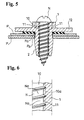
- Fig. 5 shows a condition wherein the screw grommet is actually attached to the fixing objects P by screwing a tapping screw N into the screw grommet from a state of Fig. 4
- Fig. 6 shows a state inside a screwing hole 10 in Fig. 5 , in enlarged states, respectively.
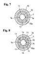
- Figs. 7 and 8 respectively show how to form a projecting portion 11 formed in an inner face 10a of the screwing hole 10, and show essential parts of modified examples which differ from the example shown in Figs. 1 to 6 .
- the screw grommet according to this embodiment is a type which fixes the fixing objects P by sandwiching the fixing objects P between a leg portion 2 and a head portion 1 such that the leg portion 2 is expanded or prevented from deflecting by screwing the tapping screw N from a state wherein the leg portion 2 is inserted into attachment holes Pa provided in the fixing objects P.
- Such screw grommet comprises the head portion 1 and the leg portion 2.
- Such screw grommet is constituted by a plastic material so as to allow the above-mentioned leg portion 2 to be expanded by screwing the above-mentioned tapping screw N, and also enable the leg portion 2 to be fitted into the above-mentioned attachment holes Pa while being elastically deformed prior to such screwing of the tapping screw N.
- the head portion 1 is constituted with a size so as not to enable it to be inserted into the attachment holes Pa of the fixing objects P such as a panel and the like.
- the leg portion 2 is integrated with the head portion 1, and constituted with a thickness so as to enable it to be inserted into such attachment holes Pa.
- the screwing hole 10 of the tapping screw N is formed in the head portion 1 in a penetrating state.
- a hole diameter of this screwing hole 10 is constituted so as to be smaller than an outer diameter of the tapping screw N to be screwed and larger than a root diameter of the tapping screw N.
- the outer diameter thereof is approximately 5.9 (5.85 to 6.0) mm
- the root diameter thereof is approximately 4.4 mm to 4.6 mm, so that the hole diameter of the screwing hole 10 is set in, for example, around 5.5 mm.
- the leg portion 2 is constituted so as to have a leg inner side space 2c which is communicated with the screwing hole 10 formed in the head portion 1 from basal portions 2a which are connected to the head portion 1 toward ends 2b.
- leg portion 2 is constituted so as to divide a tubular body, formed such that one end of a tube is communicated with the above-mentioned screwing hole 10 and integrally connected to one face side of the head portion 1, into two or above portions by dividing grooves 2d which continue toward one end side of the tube from the other end of the tube.
- such leg portion 2 is constituted so as to be expanded by gradually deflecting the two or above leg portions 2 to the outside as a size of the insertion of the above-mentioned tapping screw N into the leg inner side space 2c increases.
- the projecting portion 11 filling a screw groove Na of the tapping screw N to be screwed is formed in the inner face 10a of the above-mentioned screwing hole 10.
- the projecting portion 11 is formed from the inner face 10a of the screwing hole 10 with a hole diameter with an intermediate size between the outer diameter and the root diameter of the tapping screw N to be screwed so as not to cause a problem for the screwing of this tapping screw N, and also so as to have a projecting size which fills watertight the screw groove Na of the tapping screw N in a formation position of the projecting portion 11.
- the leg portion 2 is passed through the attachment holes Pa from a state wherein the fixing objects P, wherein the attachment holes Pa with a size passing through the leg portion 2 but not the head portion 1 thereof is provided, typically, two or above sheets of panels P comprising such attachment holes Pa, are overlaid so that the respective attachment holes Pa are communicated.
- the tapping screw N is screwed from the screwing hole 10 of the head portion 1, so that the fixing objects P are fixed so as to be sandwiched between such head portion 1 and the expanded leg portion 2.
- the screwing hole 10 has the hole diameter with the intermediate size between the outer diameter and the root diameter of the tapping screw N, an excessive force is not required for such screwing.
- the screw groove Na of such tapping screw N can be a flow channel for such liquid.
- the projecting portion 11 fills the screw groove Na watertight, so that the further entry of the liquid from the formation position can be prevented.
- a ring-like seal member which functions so as to become a seat of a head of the tapping screw N through an axis of the tapping screw N, the tapping screw N and the screwing hole 10 can be sealed watertight.
- the head portion 1 includes a flange-like portion 12 as the center of the screwing hole 10.
- a flange-like portion 12 is constituted so as to form a discoid.
- a short-sized tubular portion 13 whose inside is the screwing hole 10 is provided such that one end of the tube is projected so as to be integrally connected to one face 12a of this flange-like portion 12.
- the screwing hole 10 expands the diameter.
- a face positioned in a hole axis direction of the screwing hole 10 in an expanded diameter portion 10b becomes an introduction guiding face 10c of the tapping screw N which gradually slants in a direction narrowing the diameter of this expanded diameter portion 10b as going toward one end side of the tube of the short-sized tubular portion 13.
- the leg portion 2 is constituted such that one end of the tube is integrally connected to the other face 12b of the flange-like portion 12 so that a space inside the tube is communicated with the screwing hole 10, and also such that the other end of the tube is open and has an outside shape of an angular tube shape.
- An outline shape of such leg portion 2 copies a hole shape of the attachment holes Pa of the fixing objects P, so that at the time of screwing the tapping screw N, a screw grommet side does not rotate together.
- arc-like inner faces 2e which are continued to the inner face 10a of the circular screwing hole 10, are formed from the basal portions 2a thereof toward the ends 2b.
- the inner faces 2e of such leg portion 2 are positioned on arcs of an imaginary circle in a cross-sectional surface perpendicular to a roughly projecting direction of the leg portion 2.
- the inner diameter forming the inner faces 2e of the leg portion 2 gradually decreases as going toward the ends 2b from the basal portions 2a of the leg portion 2.
- such leg portion 2 is divided into two by the dividing grooves 2d which continue from the ends 2b thereof to the basal portions 2a.
- the leg portion 2 is divided into two.
- such leg portion 2 is constituted such that the outside thereof gradually increases toward approximately middle positions 2f in a tube axis direction from the basal portions 2a thereof, and that the outside thereof gradually narrows toward the ends 2b thereof from the approximately middle positions 2f.
- a thickness of the approximately middle positions 2f is made slightly larger than a hole width of the above-mentioned attachment holes Pa.
- the above-mentioned projecting portion 11 is respectively formed on both sides in a diametrical direction of the screwing hole 10.
- the respective projecting portion 11 is constituted so as to form a rib shape continuing along a hole axis of the screwing hole 10, and continues starting from an inner end of the expanded diameter portion 10b of the short-sized tubular portion 13 of the head portion 1 up to the ends 2b of the leg portion 2.
- the inside of the leg portion 2 is constituted so as to be gradually narrowed as going toward the ends 2b thereof, such projecting portion 11 is relatively gradually lowered as going toward the ends 2b of the leg portion 2.
- the projecting portion 11 reaches to the point continued to the inner faces 2e of the leg portion 2 on the ends 2b of the leg portion 2.
- the screw groove Na of the tapping screw N to be screwed inside the head portion 1 can be reliably filled by the above-mentioned projecting portion 11 at any position of a helix thereof.
- at least one portion of such projecting portion 11 is formed in the inner face 10a of the screwing hole 10 in the above-mentioned flange-like portion 12.
- this flange-like portion 12 is provided with a thickness of a size for one pitch portion or above of the tapping screw N to be screwed.
- the above-mentioned projecting portion 11 can be firmly and reliably filled by screwing the tapping screw N to be screwed into the screw groove Na in the inner side of this flange-like portion 12.
- such projecting portion 11 may be formed so as to continue in a circumferential direction thereof inside the screwing hole 10. Even in this case, the screwing groove Na of the tapping screw N to be screwed inside the head portion 1 can be reliably filled by such projecting portion 11 at any position of the helix thereof.
- the projecting portion 11 is not formed around the whole circumference of the screwing hole 10, and is formed by forming gaps 14 between adjacent projecting portion 11 in the circumferential direction of this screwing hole 10, and by dividing the projecting portion 11 into two or above. At the time of the screwing of the tapping screw N, such gaps 14 can be functioned as a thickness escape, and a force required for screwing the tapping screw N can be reduced.
- both a top portion 11a and bottom portions 11b of the projecting portion 11 are formed so as to be a curve.
- the projecting portion 11 is curved such that the top portion 11a is formed in a dome shape, and also such that both bottom portions 11b, 11b are formed such that the internal side of the screwing hole 10 is the inside of the curve.
- the projecting portion 11 can be prevented from being fractured and scraped from the inner face 10a of the screwing hole 10. Also, in an aspect without causing a problem for the screwing of the tapping screw N, a thickness amount of the projecting portion 11 can be increased.
- the projecting portion 11 was projected from the inner face 10a of the screwing hole 10 such that the projecting portion 11 was entered into the inside of an imaginary circle within a range of 0.1 mm to 0.2 mm rather than a circumferential face of an imaginary cylinder which was in contact with the bottom of the root of the tapping screw N to be screwed, i.e., an arc of the imaginary circle wherein the root diameter of the tapping screw N was the diameter. Also, by setting the hole diameter of the screwing hole 10 at 5.5 mm, the tapping screw with the nominal diameter 6 specified by the JIS was screwed in. As a result, this screwing could be smoothly carried out. Meanwhile, this tapping screw and the screwing hole 10 could be reliably sealed watertight.
- the tapping screw N is screwed by inserting the leg portion 2 into the attachment holes Pa of the fixing objects P, in a state wherein the leg portion 2 is passed through a through hole 3a of a plate-like seal material 3 which is provided with the through hole 3a for the leg portion 2 and made of rubber or plastic with rubber-like elasticity. Also, the other face 12b of the flange-like portion 12 and the fixing objects P are sealed watertight by this plate-like seal material 3.
- all contents of the specification, claims, drawings, and abstract of Japanese Patent Application No. 2008-75268 filed on March 24, 2008 are cited in their entirety herein and are incorporated as a disclosure of the specification of the present invention.
Landscapes
- Engineering & Computer Science (AREA)
- General Engineering & Computer Science (AREA)
- Mechanical Engineering (AREA)
- Dowels (AREA)
- Gasket Seals (AREA)
- Bolts, Nuts, And Washers (AREA)
Abstract
Description
- This invention relates to an improvement of a screw grommet with a type of fixing a fixing object by sandwiching the fixing object between a leg portion and a head portion such that the leg portion is expanded or prevented from deflecting by screwing a tapping screw (also called Tappin screw) thereinto from a state wherein the leg portion is inserted into an attachment hole provided in the fixing object.
- In a case where panels constituting an automobile and the like are fixed to each other, there is a case wherein watertightness and the like are required for a fixing portion by a screw grommet. In this case, the sealing between the attachment hole formed in the panel and the like and the screw grommet, and the sealing between the screw grommet and a screw which is screwed thereinto, are required. In such case, conventionally, a washer-like body with elasticity on a lower face side of a flange of the screw grommet was disposed, and also the washer-like body with the elasticity on a lower face side of a head of the screw was disposed.
- Incidentally, as a screw grommet wherein an opening of a screwing hole of screw means is covered by a hot-melt material, there is a screw grommet shown in
Patent Document 1. Also, as a screw grommet with a structure comprising a seal washer on a lower face of the flange, there is a screw grommet shown inPatent Document 2.
Patent Document 1: Japanese Unexamined Patent Publication No.S58-24646
Patent Document 2: Japanese Utility Model Publication No.H06-24220 - A main object to be solved by the present invention is that in this kind of screw grommet, a tapping screw and a screwing hole thereof in the screw grommet can be reliably sealed without providing a separate seal member therebetween.
- In order to achieve the above-mentioned object, in the present invention, a screw grommet is a plastic screw grommet provided with a head portion comprising a screwing hole for a tapping screw, and a leg portion expanded or prevented from deflecting by screwing the tapping screw. A hole diameter of the screwing hole is made smaller than an outer diameter of the above-mentioned tapping screw and larger than a root diameter of the tapping screw. Also, a projecting portion for filling a screw groove of the tapping screw to be screwed is formed in an inner face of the screwing hole.
- In such screw grommet, the leg portion is passed through, or fitted into an attachment hole for a fixing object wherein an attachment hole with a size passing through the leg portion but not the head portion thereof is provided. Next, the tapping screw is screwed from the screwing hole of the head portion, so that the screw grommet is fixed to the fixing object such that the fixing object is sandwiched between such head portion and the leg portion expanded or prevented from deflecting. Since the screwing hole has the hole diameter with an intermediate size between the outer diameter and the root diameter of the tapping screw, an excessive force is not required for such screwing. Accordingly, under a circumstance wherein a liquid such as water and the like is entered between the screwed tapping screw and the screwing hole, a screw groove of such tapping screw can be a flow channel for such liquid. However, in a formation position of the above-mentioned projecting portion, this projecting portion fills the screw groove watertight, so that the further entry of the liquid from this formation position can be prevented.
- If the above-mentioned projecting portion is formed so as to form a rib shape continuing along a hole axis of the screwing hole, or if such projecting portion is formed so as to continue in a circumferential direction of the screwing hole, the screw groove of the tapping screw to be screwed inside the head portion can be reliably filled by the above-mentioned projecting portion at any position of a helix thereof.
- The above-mentioned head portion may include a flange-like portion as the center of the screwing hole, and also at least one portion of the projecting portion may be formed in an inner face of the screwing hole in this flange-like portion. In this case, further, the flange-like portion may be provided with a thickness of a size for one pitch portion or above of the tapping screw to be screwed. Since the rigidity of the flange-like portion increases, by doing this, the above-mentioned projecting portion can be firmly and reliably filled by screwing the tapping screw to be screwed into the screw groove in the inner side of this flange-like portion.
- In a cross-sectional surface perpendicular to the hole axis of the screwing hole, the projecting portion may be formed such that both a top portion and a bottom portion of the projecting portion form a curve. By doing this, at the time of the screwing of the tapping screw, the projecting portion is damaged by a thread of the screw. However, at this time, the projecting portion can be prevented from being fractured and scraped from the inner face of the screwing hole. Also, in a range without causing a problem for the screwing of the tapping screw, a thickness amount of the projecting portion can be increased.
- Also, such projecting portion may be projected from the inner face of the screwing hole so that the projecting portion is entered into the inside of an imaginary circle within a range of 0.1 mm to 0.2 mm rather than an arc of the imaginary circle wherein the root diameter of the tapping screw to be screwed is a diameter. In such case, the above-mentioned screwing of the tapping screw can be carried out smoothly, and also the tapping screw and the screwing hole can be reliably sealed.
- According to such screw grommet of the present invention, the screw groove of the tapping screw can be filled by the projecting portion formed in the inner face of the screwing hole of the tapping screw, so that the tapping screw and the screwing hole in the screw grommet can be reliably sealed without providing a separate seal member therebetween.
-
-
Fig. 1 is a side view of a screw grommet. -
Fig. 2 is a bottom view of the above. -
Fig. 3 is a sectional view taken along line A-A inFig. 1 . -
Fig. 4 is a cross sectional view showing a temporary attached state of the screw grommet in a position of line B-B inFig. 2 . -
Fig. 5 is a cross sectional view showing an actually attached state of the screw grommet. -
Fig. 6 is an enlarged view of essential parts ofFig. 5 . -
Fig. 7 is a cross sectional view of essential parts of one example wherein one portion of the structure of the screw grommet shown inFigs. 1 to 6 is changed. -
Fig. 8 is a cross sectional view of the essential parts of the other example wherein one portion of the structure of the screw grommet shown inFigs. 1 to 6 is changed. - Hereinafter, best modes of the present invention will be explained with reference to
Figs. 1 to 8 . - Incidentally, here,
Figs. 1 to 3 respectively show one example of a screw grommet structured by applying the present invention.Fig. 4 shows a condition wherein such screw grommet is temporarily attached to fixing objects P,Fig. 5 shows a condition wherein the screw grommet is actually attached to the fixing objects P by screwing a tapping screw N into the screw grommet from a state ofFig. 4 , andFig. 6 shows a state inside ascrewing hole 10 inFig. 5 , in enlarged states, respectively. Also,Figs. 7 and 8 respectively show how to form a projectingportion 11 formed in aninner face 10a of thescrewing hole 10, and show essential parts of modified examples which differ from the example shown inFigs. 1 to 6 . - The screw grommet according to this embodiment is a type which fixes the fixing objects P by sandwiching the fixing objects P between a
leg portion 2 and ahead portion 1 such that theleg portion 2 is expanded or prevented from deflecting by screwing the tapping screw N from a state wherein theleg portion 2 is inserted into attachment holes Pa provided in the fixing objects P. - Such screw grommet comprises the
head portion 1 and theleg portion 2. Such screw grommet is constituted by a plastic material so as to allow the above-mentionedleg portion 2 to be expanded by screwing the above-mentioned tapping screw N, and also enable theleg portion 2 to be fitted into the above-mentioned attachment holes Pa while being elastically deformed prior to such screwing of the tapping screw N. - The
head portion 1 is constituted with a size so as not to enable it to be inserted into the attachment holes Pa of the fixing objects P such as a panel and the like. Theleg portion 2 is integrated with thehead portion 1, and constituted with a thickness so as to enable it to be inserted into such attachment holes Pa. - The
screwing hole 10 of the tapping screw N is formed in thehead portion 1 in a penetrating state. A hole diameter of thisscrewing hole 10 is constituted so as to be smaller than an outer diameter of the tapping screw N to be screwed and larger than a root diameter of the tapping screw N. For example, in a case where the tapping screw N to be screwed is a type 4 Tappin screw with a nominal diameter 6 specified by Japanese Industrial Standards (JIS), the outer diameter thereof is approximately 5.9 (5.85 to 6.0) mm, and the root diameter thereof is approximately 4.4 mm to 4.6 mm, so that the hole diameter of thescrewing hole 10 is set in, for example, around 5.5 mm. - The
leg portion 2 is constituted so as to have a leginner side space 2c which is communicated with thescrewing hole 10 formed in thehead portion 1 frombasal portions 2a which are connected to thehead portion 1 towardends 2b. Typically,such leg portion 2 is constituted so as to divide a tubular body, formed such that one end of a tube is communicated with the above-mentionedscrewing hole 10 and integrally connected to one face side of thehead portion 1, into two or above portions by dividinggrooves 2d which continue toward one end side of the tube from the other end of the tube. In an illustrated example,such leg portion 2 is constituted so as to be expanded by gradually deflecting the two or aboveleg portions 2 to the outside as a size of the insertion of the above-mentioned tapping screw N into the leginner side space 2c increases. - In this embodiment, the projecting
portion 11 filling a screw groove Na of the tapping screw N to be screwed is formed in theinner face 10a of the above-mentionedscrewing hole 10. Concretely, in this embodiment, the projectingportion 11 is formed from theinner face 10a of thescrewing hole 10 with a hole diameter with an intermediate size between the outer diameter and the root diameter of the tapping screw N to be screwed so as not to cause a problem for the screwing of this tapping screw N, and also so as to have a projecting size which fills watertight the screw groove Na of the tapping screw N in a formation position of the projectingportion 11. - In such screw grommet, the
leg portion 2 is passed through the attachment holes Pa from a state wherein the fixing objects P, wherein the attachment holes Pa with a size passing through theleg portion 2 but not thehead portion 1 thereof is provided, typically, two or above sheets of panels P comprising such attachment holes Pa, are overlaid so that the respective attachment holes Pa are communicated. (Fig. 4 ) Next, the tapping screw N is screwed from thescrewing hole 10 of thehead portion 1, so that the fixing objects P are fixed so as to be sandwiched betweensuch head portion 1 and the expandedleg portion 2. (Fig. 5 ) Since thescrewing hole 10 has the hole diameter with the intermediate size between the outer diameter and the root diameter of the tapping screw N, an excessive force is not required for such screwing. Accordingly, under a circumstance wherein a liquid such as water and the like is entered between the screwed tapping screw N and thescrewing hole 10, the screw groove Na of such tapping screw N can be a flow channel for such liquid. However, in the formation position of the above-mentioned projectingportion 11, the projectingportion 11 fills the screw groove Na watertight, so that the further entry of the liquid from the formation position can be prevented. Specifically, according to such screw grommet, without using a separate waterproof means between the screwinghole 10 and the tapping screw N, typically, a ring-like seal member which functions so as to become a seat of a head of the tapping screw N through an axis of the tapping screw N, the tapping screw N and the screwinghole 10 can be sealed watertight. - In the illustrated example, the
head portion 1 includes a flange-like portion 12 as the center of the screwinghole 10. Such flange-like portion 12 is constituted so as to form a discoid. On oneface 12a side of the flange-like portion 12, a short-sized tubular portion 13 whose inside is the screwinghole 10 is provided such that one end of the tube is projected so as to be integrally connected to oneface 12a of this flange-like portion 12. On the other end of the tube of this short-sized tubular portion 13, the screwinghole 10 expands the diameter. A face positioned in a hole axis direction of the screwinghole 10 in an expandeddiameter portion 10b becomes anintroduction guiding face 10c of the tapping screw N which gradually slants in a direction narrowing the diameter of this expandeddiameter portion 10b as going toward one end side of the tube of the short-sized tubular portion 13. - Also, in the illustrated example, the
leg portion 2 is constituted such that one end of the tube is integrally connected to theother face 12b of the flange-like portion 12 so that a space inside the tube is communicated with the screwinghole 10, and also such that the other end of the tube is open and has an outside shape of an angular tube shape. An outline shape ofsuch leg portion 2 copies a hole shape of the attachment holes Pa of the fixing objects P, so that at the time of screwing the tapping screw N, a screw grommet side does not rotate together. Inside theleg portion 2, arc-like inner faces 2e, which are continued to theinner face 10a of the circular screwinghole 10, are formed from thebasal portions 2a thereof toward theends 2b. The inner faces 2e ofsuch leg portion 2 are positioned on arcs of an imaginary circle in a cross-sectional surface perpendicular to a roughly projecting direction of theleg portion 2. The inner diameter forming theinner faces 2e of theleg portion 2 gradually decreases as going toward theends 2b from thebasal portions 2a of theleg portion 2. - In the illustrated figure,
such leg portion 2 is divided into two by the dividinggrooves 2d which continue from theends 2b thereof to thebasal portions 2a. Concretely, roughly the center of both side faces which are in a back-to-back direction of theleg portion 2 whose outer side is the angular tube shape, is respectively divided into two by the above-mentioneddividing grooves 2d. Bysuch dividing grooves 2d of two portions, theleg portion 2 is divided into two. Also,such leg portion 2 is constituted such that the outside thereof gradually increases toward approximatelymiddle positions 2f in a tube axis direction from thebasal portions 2a thereof, and that the outside thereof gradually narrows toward theends 2b thereof from the approximatelymiddle positions 2f. Also, a thickness of the approximatelymiddle positions 2f is made slightly larger than a hole width of the above-mentioned attachment holes Pa. Thereby, in the illustrated example, by inserting theleg portion 2 into the attachment holes Pa of the fixing objects P, after theleg portion 2 is elastically deformed inwardly once, theleg portion 2 is allowed to elastically return at a position wherein the above-mentioned approximatelymiddle positions 2f are slipped out of a hole margin on an inserting end side of the attachment holes Pa, so that theleg portion 2 can be temporarily attached to the attachment holes Pa. (Fig. 4 ) - Also, in the illustrated example, the above-mentioned projecting
portion 11 is respectively formed on both sides in a diametrical direction of the screwinghole 10. The respective projectingportion 11 is constituted so as to form a rib shape continuing along a hole axis of the screwinghole 10, and continues starting from an inner end of the expandeddiameter portion 10b of the short-sized tubular portion 13 of thehead portion 1 up to theends 2b of theleg portion 2. As mentioned above, since the inside of theleg portion 2 is constituted so as to be gradually narrowed as going toward theends 2b thereof, such projectingportion 11 is relatively gradually lowered as going toward theends 2b of theleg portion 2. Then, the projectingportion 11 reaches to the point continued to the inner faces 2e of theleg portion 2 on theends 2b of theleg portion 2. Thereby, the screw groove Na of the tapping screw N to be screwed inside thehead portion 1 can be reliably filled by the above-mentioned projectingportion 11 at any position of a helix thereof. In the illustrated example, due to such structure, at least one portion of such projectingportion 11 is formed in theinner face 10a of the screwinghole 10 in the above-mentioned flange-like portion 12. Also, this flange-like portion 12 is provided with a thickness of a size for one pitch portion or above of the tapping screw N to be screwed. Since the rigidity of the flange-like portion 12 increases, by doing this, the above-mentioned projectingportion 11 can be firmly and reliably filled by screwing the tapping screw N to be screwed into the screw groove Na in the inner side of this flange-like portion 12. - As shown in
Figs. 7, 8 , such projectingportion 11 may be formed so as to continue in a circumferential direction thereof inside the screwinghole 10. Even in this case, the screwing groove Na of the tapping screw N to be screwed inside thehead portion 1 can be reliably filled by such projectingportion 11 at any position of the helix thereof. In this case, the projectingportion 11 is not formed around the whole circumference of the screwinghole 10, and is formed by forminggaps 14 between adjacent projectingportion 11 in the circumferential direction of this screwinghole 10, and by dividing the projectingportion 11 into two or above. At the time of the screwing of the tapping screw N,such gaps 14 can be functioned as a thickness escape, and a force required for screwing the tapping screw N can be reduced. - Also, in the illustrated example, in a cross-sectional surface perpendicular to the hole axis of the screwing
hole 10, both atop portion 11a andbottom portions 11b of the projectingportion 11 are formed so as to be a curve. (Fig. 3 ) Concretely, in a shape of the above-mentioned cross-sectional surface, the projectingportion 11 is curved such that thetop portion 11a is formed in a dome shape, and also such that bothbottom portions hole 10 is the inside of the curve. By doing this, at the time of the screwing of the tapping screw N, the projectingportion 11 is damaged by a thread of the screw. However, at this time, the projectingportion 11 can be prevented from being fractured and scraped from theinner face 10a of the screwinghole 10. Also, in an aspect without causing a problem for the screwing of the tapping screw N, a thickness amount of the projectingportion 11 can be increased. - The projecting
portion 11 was projected from theinner face 10a of the screwinghole 10 such that the projectingportion 11 was entered into the inside of an imaginary circle within a range of 0.1 mm to 0.2 mm rather than a circumferential face of an imaginary cylinder which was in contact with the bottom of the root of the tapping screw N to be screwed, i.e., an arc of the imaginary circle wherein the root diameter of the tapping screw N was the diameter. Also, by setting the hole diameter of the screwinghole 10 at 5.5 mm, the tapping screw with the nominal diameter 6 specified by the JIS was screwed in. As a result, this screwing could be smoothly carried out. Meanwhile, this tapping screw and the screwinghole 10 could be reliably sealed watertight. - Incidentally, in the illustrated example, the tapping screw N is screwed by inserting the
leg portion 2 into the attachment holes Pa of the fixing objects P, in a state wherein theleg portion 2 is passed through a throughhole 3a of a plate-like seal material 3 which is provided with the throughhole 3a for theleg portion 2 and made of rubber or plastic with rubber-like elasticity. Also, theother face 12b of the flange-like portion 12 and the fixing objects P are sealed watertight by this plate-like seal material 3.
Incidentally, all contents of the specification, claims, drawings, and abstract of Japanese Patent Application No.2008-75268 filed on March 24, 2008
Claims (7)
- A screw grommet which is made of plastic, comprising:a head portion provided with a screwing hole for a tapping screw; anda leg portion expanding by screwing the tapping screw or preventing deflection thereof, andwherein a hole diameter of the screwing hole is made smaller than an outer diameter of said tapping screw and larger than a root diameter of the tapping screw, anda projecting portion for filling a screw groove of the tapping screw to be screwed is formed in an inner face of the screwing hole.
- A screw grommet according to claim 1, wherein the projecting portion is formed so as to form a rib shape continuing along a hole axis of the screwing hole.
- A screw grommet according to claim 1, wherein the projecting portion is formed so as to continue in a circumferential direction of the screwing hole.
- A screw grommet according to any one of claims 1 to 3, wherein the head portion includes a flange portion as a center of the screwing hole, and also at least one portion of the projecting portion is formed in an inner face of the screwing hole in the flange portion.
- A screw grommet according to claim 4, wherein the flange portion is provided with a thickness of a size for one pitch portion or above of the tapping screw to be screwed.
- A screw grommet according to claim 2, wherein in a cross-sectional surface perpendicular to the hole axis of the screwing hole, a top portion and bottom portions of the projecting portion are formed so as to form a curve.
- A screw grommet according to any one of claims 1 to 6, wherein the projecting portion projects from the inner face of the screwing hole so as to be entered into an inside of an imaginary circle within a range of 0.1 mm to 0.2 mm rather than an arc of the imaginary circle wherein a diameter is the root diameter of the tapping screw to be screwed.
Applications Claiming Priority (2)
| Application Number | Priority Date | Filing Date | Title |
|---|---|---|---|
| JP2008075268A JP5054587B2 (en) | 2008-03-24 | 2008-03-24 | Screw grommet |
| PCT/JP2009/055446 WO2009119446A1 (en) | 2008-03-24 | 2009-03-19 | Screw grommet |
Publications (3)
| Publication Number | Publication Date |
|---|---|
| EP2275691A1 true EP2275691A1 (en) | 2011-01-19 |
| EP2275691A4 EP2275691A4 (en) | 2013-01-02 |
| EP2275691B1 EP2275691B1 (en) | 2014-06-11 |
Family
ID=41113641
Family Applications (1)
| Application Number | Title | Priority Date | Filing Date |
|---|---|---|---|
| EP09723665.7A Active EP2275691B1 (en) | 2008-03-24 | 2009-03-19 | Screw grommet |
Country Status (7)
| Country | Link |
|---|---|
| US (1) | US8931988B2 (en) |
| EP (1) | EP2275691B1 (en) |
| JP (1) | JP5054587B2 (en) |
| KR (1) | KR20100109570A (en) |
| CN (1) | CN101978177B (en) |
| ES (1) | ES2493019T3 (en) |
| WO (1) | WO2009119446A1 (en) |
Cited By (1)
| Publication number | Priority date | Publication date | Assignee | Title |
|---|---|---|---|---|
| DE202022000594U1 (en) | 2022-03-09 | 2022-03-17 | Wenko-Wenselaar GmbH & Co. Kommanditgesellschaft | Device for attaching an object to packaging |
Families Citing this family (20)
| Publication number | Priority date | Publication date | Assignee | Title |
|---|---|---|---|---|
| JP5830289B2 (en) * | 2011-07-20 | 2015-12-09 | 株式会社カネカ | Fixing device, mounting method of solar cell module mounting device and roof structure |
| US8661614B2 (en) | 2011-08-17 | 2014-03-04 | Symmetry Medical Manufacturing, Inc. | Grommet device with flexible bowed members and methods of using thereof |
| US8701246B2 (en) * | 2011-09-14 | 2014-04-22 | Symmetry Medical Manufacturing, Inc. | Removable grommet device and method of using thereof |
| US9277967B2 (en) | 2011-09-14 | 2016-03-08 | Symmetry Medical Manufacturing, Inc. | Universally-sized grommet device and method thereof |
| US8739363B2 (en) | 2011-09-14 | 2014-06-03 | Symmetry Medical Manufacturing, Inc. | Removable grommet device with enlargeable slit and method thereof |
| US9915282B2 (en) * | 2012-06-06 | 2018-03-13 | Pneutools, Incorporated | Stacked caps with connecting stems |
| US9599140B2 (en) | 2014-08-28 | 2017-03-21 | Newfrey Llc | Plastic serviceable screw grommet and related methods |
| CN105716321B (en) * | 2014-12-01 | 2019-03-05 | 青岛海尔特种电冰柜有限公司 | Semiconductor refrigeration equipment |
| BR212016017126Y1 (en) * | 2015-07-23 | 2018-11-27 | Cermag Comercial Importadora E Exportadora Ltda. | component mounting arrangement for bracket and profile handle attachment |
| JP6395321B2 (en) * | 2015-10-26 | 2018-09-26 | 株式会社ニフコ | Grommet |
| CN105402232A (en) * | 2016-01-11 | 2016-03-16 | 太仓市德浩紧固件有限公司 | Self-tapping screw |
| US20170284567A1 (en) * | 2016-03-30 | 2017-10-05 | The Boeing Company | Grommet, conduit support assembly, and method of supporting a conduit |
| CN107313689A (en) * | 2017-08-21 | 2017-11-03 | 贵州协成装饰工程有限公司 | A kind of window frame reversion section bar and window frame attachment structure |
| CN107269168A (en) * | 2017-08-21 | 2017-10-20 | 贵州协成装饰工程有限公司 | A kind of outer casement window of combined type |
| ES2708863B2 (en) * | 2017-10-10 | 2020-03-25 | Itw Espana Sa | Parts fixing device |
| US10941801B2 (en) * | 2017-12-20 | 2021-03-09 | Bombardier Recreational Products Inc. | Anchor assembly |
| DE102019101078A1 (en) | 2018-01-16 | 2019-07-18 | Illinois Tool Works Inc. | NIET FASTENER ELEMENT DESIGN AND METHOD OF USE THEREOF |
| US11268557B2 (en) * | 2018-10-10 | 2022-03-08 | Illinois Tool Works Inc. | Rivet fastener assembly and method of use thereof |
| ES3031657T3 (en) * | 2019-10-09 | 2025-07-10 | Doka Gmbh | Anchor |
| CN114838047B (en) * | 2022-05-19 | 2024-02-06 | 浙江洪扬汽车零部件有限公司 | Lock screw for mechanical equipment |
Family Cites Families (33)
| Publication number | Priority date | Publication date | Assignee | Title |
|---|---|---|---|---|
| US1051444A (en) * | 1911-07-18 | 1913-01-28 | Henry B Newhall | Bolt-anchor. |
| US1248009A (en) * | 1917-01-20 | 1917-11-27 | Henry B Newhall | Bolt-anchor. |
| US1248008A (en) * | 1917-01-20 | 1917-11-27 | Henry B Newhall | Bolt-anchor. |
| US1248004A (en) * | 1917-01-20 | 1917-11-27 | Henry B Newhall | Bolt-anchor. |
| US1751818A (en) * | 1928-09-28 | 1930-03-25 | Newhall Henry B Corp | Bolt anchor |
| US1754333A (en) * | 1929-02-15 | 1930-04-15 | Newhall Henry B Corp | Bolt anchor |
| DE1207065B (en) * | 1960-05-14 | 1965-12-16 | Artur Fischer | Expanding dowel |
| JPS5338053Y2 (en) * | 1974-04-18 | 1978-09-14 | ||
| US4082030A (en) * | 1977-03-25 | 1978-04-04 | Illinois Tool Works, Inc. | Plastic screw grommet |
| JPS5653124Y2 (en) * | 1977-10-08 | 1981-12-11 | ||
| US4233881A (en) * | 1978-05-05 | 1980-11-18 | Carrier Vernon J | Wall fastener structure |
| JPS5572903A (en) * | 1978-11-21 | 1980-06-02 | Nifco Inc | Screw grommet |
| JPS5824646A (en) | 1981-08-06 | 1983-02-14 | Kazuichi Ito | Rocking type fluid-tight drive unit |
| JPS5958206U (en) * | 1982-10-12 | 1984-04-16 | 株式会社青山製作所 | Synthetic resin grommet |
| US4601625A (en) * | 1984-05-11 | 1986-07-22 | Illinois Tool Works Inc. | Self drilling threaded insert for drywall |
| JPH045766Y2 (en) * | 1984-09-07 | 1992-02-18 | ||
| JPH0435612Y2 (en) * | 1988-07-08 | 1992-08-24 | ||
| JPH0343107U (en) * | 1989-09-04 | 1991-04-23 | ||
| IT224172Z2 (en) * | 1991-01-18 | 1996-02-09 | Fischer Italia Di Paolo Morasu | GASKET ELEMENT AND SPACING FOR SHEET ANCHORING DEVICES FOR WALL COVERING |
| JPH0539808A (en) * | 1991-05-30 | 1993-02-19 | Mitsubishi Cable Ind Ltd | Seal washer |
| US5294225A (en) * | 1991-11-21 | 1994-03-15 | K.K. Aoyama Seisakusho | Synthetic resin grommet |
| JP2605155Y2 (en) | 1992-08-31 | 2000-06-26 | 株式会社パイオラックス | Screw grommet |
| JP2604678Y2 (en) | 1992-09-18 | 2000-05-22 | 株式会社東郷製作所 | Grommet |
| DE4404746C2 (en) * | 1994-02-15 | 1999-08-05 | Itw Ateco Gmbh | Plastic rivet for fastening a plate-shaped workpiece to a holder with an approximately flat surface |
| DE9413434U1 (en) * | 1994-08-19 | 1995-12-21 | Fischerwerke Artur Fischer Gmbh & Co Kg, 72178 Waldachtal | Plastic expansion anchors |
| DE69515505T2 (en) * | 1994-11-23 | 2000-09-14 | Cobra Anchors Co. Ltd., East Montreal | IMPROVEMENT ON A WALL ANCHOR |
| DE19607446A1 (en) * | 1996-02-28 | 1997-09-04 | Adolf Wuerth Gmbh & Co Kg | Knock-in dowels |
| DE19930728B4 (en) * | 1999-07-05 | 2005-12-01 | Itw-Ateco Gmbh | Anchor for fixing an object to a carrier made of flat material |
| JP3914710B2 (en) * | 2001-01-15 | 2007-05-16 | 株式会社ニフコ | Fastener |
| JP2004044644A (en) * | 2002-07-10 | 2004-02-12 | Nippon Pop Rivets & Fasteners Ltd | Screw grommet |
| ITTO20030279A1 (en) * | 2003-04-11 | 2004-10-12 | Itw Construction Products Italy Srl | EXPANSION DOWEL. |
| US7001124B2 (en) * | 2004-02-05 | 2006-02-21 | Illinois Tool Works Inc. | Anchor |
| CN201100290Y (en) * | 2007-11-13 | 2008-08-13 | 邹海微 | Expansion pipe |
-
2008
- 2008-03-24 JP JP2008075268A patent/JP5054587B2/en active Active
-
2009
- 2009-03-19 EP EP09723665.7A patent/EP2275691B1/en active Active
- 2009-03-19 WO PCT/JP2009/055446 patent/WO2009119446A1/en not_active Ceased
- 2009-03-19 CN CN200980110172.1A patent/CN101978177B/en active Active
- 2009-03-19 ES ES09723665.7T patent/ES2493019T3/en active Active
- 2009-03-19 US US12/736,219 patent/US8931988B2/en active Active
- 2009-03-19 KR KR1020107019921A patent/KR20100109570A/en not_active Ceased
Non-Patent Citations (2)
| Title |
|---|
| No further relevant documents disclosed * |
| See also references of WO2009119446A1 * |
Cited By (1)
| Publication number | Priority date | Publication date | Assignee | Title |
|---|---|---|---|---|
| DE202022000594U1 (en) | 2022-03-09 | 2022-03-17 | Wenko-Wenselaar GmbH & Co. Kommanditgesellschaft | Device for attaching an object to packaging |
Also Published As
| Publication number | Publication date |
|---|---|
| US20110091301A1 (en) | 2011-04-21 |
| JP5054587B2 (en) | 2012-10-24 |
| ES2493019T3 (en) | 2014-09-11 |
| EP2275691A4 (en) | 2013-01-02 |
| CN101978177A (en) | 2011-02-16 |
| US8931988B2 (en) | 2015-01-13 |
| KR20100109570A (en) | 2010-10-08 |
| JP2009228802A (en) | 2009-10-08 |
| WO2009119446A1 (en) | 2009-10-01 |
| CN101978177B (en) | 2012-08-29 |
| EP2275691B1 (en) | 2014-06-11 |
Similar Documents
| Publication | Publication Date | Title |
|---|---|---|
| EP2275691B1 (en) | Screw grommet | |
| US8656553B2 (en) | Grommet for wire harness | |
| EP2679515B1 (en) | Venting device | |
| JP2012163132A (en) | Tube joint | |
| JP6259357B2 (en) | Piping connection structure and connecting member | |
| KR20060049017A (en) | Sealed Mulberry Nut Plate | |
| KR20010101662A (en) | Device for quick connection of a tube to a rigid element | |
| BR112013017608B1 (en) | FUEL INJECTION DEVICE | |
| US12038036B2 (en) | Seal with skirt | |
| EP2818688A1 (en) | Sealing structure | |
| KR200443289Y1 (en) | Cable waterproof packing structure | |
| EP3915176A1 (en) | Cable feedthrough for feeding a cable through a separating element, and assembly | |
| KR102865890B1 (en) | pipe joints | |
| JP2007309422A (en) | Fastening structure using bolt and manufacturing method thereof | |
| JP2020125655A (en) | Pc steel bar body and construction method of pc steel bar body | |
| JP3244782U (en) | Container opening sealing structure and packing | |
| DE102012006524A1 (en) | Screw with a guide element | |
| CN215410168U (en) | Stopping and anti-falling rubber ring | |
| JP7793095B1 (en) | Fastening members and functional members | |
| KR102551673B1 (en) | Tube holder for vehicle | |
| EP4660016A1 (en) | Grommet and cable bushing and method for producing the cable bushing | |
| US11072081B2 (en) | Robot sealing structure and robot | |
| EP3713025A1 (en) | Lead feedthrough with direction | |
| US20170314609A1 (en) | Seal structure and control cable unit | |
| JPH0531035U (en) | Cord holder |
Legal Events
| Date | Code | Title | Description |
|---|---|---|---|
| PUAI | Public reference made under article 153(3) epc to a published international application that has entered the european phase |
Free format text: ORIGINAL CODE: 0009012 |
|
| 17P | Request for examination filed |
Effective date: 20100924 |
|
| AK | Designated contracting states |
Kind code of ref document: A1 Designated state(s): AT BE BG CH CY CZ DE DK EE ES FI FR GB GR HR HU IE IS IT LI LT LU LV MC MK MT NL NO PL PT RO SE SI SK TR |
|
| AX | Request for extension of the european patent |
Extension state: AL BA RS |
|
| DAX | Request for extension of the european patent (deleted) | ||
| A4 | Supplementary search report drawn up and despatched |
Effective date: 20121130 |
|
| RIC1 | Information provided on ipc code assigned before grant |
Ipc: F16B 13/04 20060101AFI20121126BHEP Ipc: F16J 15/10 20060101ALI20121126BHEP Ipc: F16B 13/14 20060101ALI20121126BHEP |
|
| RIC1 | Information provided on ipc code assigned before grant |
Ipc: F16B 37/04 20060101ALI20130918BHEP Ipc: F16J 15/10 20060101ALI20130918BHEP Ipc: F16B 13/04 20060101AFI20130918BHEP Ipc: F16B 13/14 20060101ALI20130918BHEP Ipc: F16B 43/00 20060101ALI20130918BHEP Ipc: F16B 5/06 20060101ALI20130918BHEP |
|
| GRAP | Despatch of communication of intention to grant a patent |
Free format text: ORIGINAL CODE: EPIDOSNIGR1 |
|
| INTG | Intention to grant announced |
Effective date: 20140102 |
|
| GRAS | Grant fee paid |
Free format text: ORIGINAL CODE: EPIDOSNIGR3 |
|
| GRAA | (expected) grant |
Free format text: ORIGINAL CODE: 0009210 |
|
| AK | Designated contracting states |
Kind code of ref document: B1 Designated state(s): AT BE BG CH CY CZ DE DK EE ES FI FR GB GR HR HU IE IS IT LI LT LU LV MC MK MT NL NO PL PT RO SE SI SK TR |
|
| REG | Reference to a national code |
Ref country code: GB Ref legal event code: FG4D |
|
| REG | Reference to a national code |
Ref country code: CH Ref legal event code: EP |
|
| REG | Reference to a national code |
Ref country code: IE Ref legal event code: FG4D |
|
| REG | Reference to a national code |
Ref country code: AT Ref legal event code: REF Ref document number: 672410 Country of ref document: AT Kind code of ref document: T Effective date: 20140715 |
|
| REG | Reference to a national code |
Ref country code: DE Ref legal event code: R096 Ref document number: 602009024590 Country of ref document: DE Effective date: 20140724 |
|
| REG | Reference to a national code |
Ref country code: ES Ref legal event code: FG2A Ref document number: 2493019 Country of ref document: ES Kind code of ref document: T3 Effective date: 20140911 |
|
| PG25 | Lapsed in a contracting state [announced via postgrant information from national office to epo] |
Ref country code: NO Free format text: LAPSE BECAUSE OF FAILURE TO SUBMIT A TRANSLATION OF THE DESCRIPTION OR TO PAY THE FEE WITHIN THE PRESCRIBED TIME-LIMIT Effective date: 20140911 Ref country code: GR Free format text: LAPSE BECAUSE OF FAILURE TO SUBMIT A TRANSLATION OF THE DESCRIPTION OR TO PAY THE FEE WITHIN THE PRESCRIBED TIME-LIMIT Effective date: 20140912 Ref country code: LT Free format text: LAPSE BECAUSE OF FAILURE TO SUBMIT A TRANSLATION OF THE DESCRIPTION OR TO PAY THE FEE WITHIN THE PRESCRIBED TIME-LIMIT Effective date: 20140611 Ref country code: FI Free format text: LAPSE BECAUSE OF FAILURE TO SUBMIT A TRANSLATION OF THE DESCRIPTION OR TO PAY THE FEE WITHIN THE PRESCRIBED TIME-LIMIT Effective date: 20140611 |
|
| REG | Reference to a national code |
Ref country code: NL Ref legal event code: VDEP Effective date: 20140611 |
|
| REG | Reference to a national code |
Ref country code: AT Ref legal event code: MK05 Ref document number: 672410 Country of ref document: AT Kind code of ref document: T Effective date: 20140611 |
|
| REG | Reference to a national code |
Ref country code: LT Ref legal event code: MG4D |
|
| PG25 | Lapsed in a contracting state [announced via postgrant information from national office to epo] |
Ref country code: LV Free format text: LAPSE BECAUSE OF FAILURE TO SUBMIT A TRANSLATION OF THE DESCRIPTION OR TO PAY THE FEE WITHIN THE PRESCRIBED TIME-LIMIT Effective date: 20140611 Ref country code: SE Free format text: LAPSE BECAUSE OF FAILURE TO SUBMIT A TRANSLATION OF THE DESCRIPTION OR TO PAY THE FEE WITHIN THE PRESCRIBED TIME-LIMIT Effective date: 20140611 Ref country code: HR Free format text: LAPSE BECAUSE OF FAILURE TO SUBMIT A TRANSLATION OF THE DESCRIPTION OR TO PAY THE FEE WITHIN THE PRESCRIBED TIME-LIMIT Effective date: 20140611 |
|
| PG25 | Lapsed in a contracting state [announced via postgrant information from national office to epo] |
Ref country code: EE Free format text: LAPSE BECAUSE OF FAILURE TO SUBMIT A TRANSLATION OF THE DESCRIPTION OR TO PAY THE FEE WITHIN THE PRESCRIBED TIME-LIMIT Effective date: 20140611 Ref country code: RO Free format text: LAPSE BECAUSE OF FAILURE TO SUBMIT A TRANSLATION OF THE DESCRIPTION OR TO PAY THE FEE WITHIN THE PRESCRIBED TIME-LIMIT Effective date: 20140611 Ref country code: CZ Free format text: LAPSE BECAUSE OF FAILURE TO SUBMIT A TRANSLATION OF THE DESCRIPTION OR TO PAY THE FEE WITHIN THE PRESCRIBED TIME-LIMIT Effective date: 20140611 Ref country code: SK Free format text: LAPSE BECAUSE OF FAILURE TO SUBMIT A TRANSLATION OF THE DESCRIPTION OR TO PAY THE FEE WITHIN THE PRESCRIBED TIME-LIMIT Effective date: 20140611 Ref country code: PT Free format text: LAPSE BECAUSE OF FAILURE TO SUBMIT A TRANSLATION OF THE DESCRIPTION OR TO PAY THE FEE WITHIN THE PRESCRIBED TIME-LIMIT Effective date: 20141013 |
|
| PG25 | Lapsed in a contracting state [announced via postgrant information from national office to epo] |
Ref country code: IS Free format text: LAPSE BECAUSE OF FAILURE TO SUBMIT A TRANSLATION OF THE DESCRIPTION OR TO PAY THE FEE WITHIN THE PRESCRIBED TIME-LIMIT Effective date: 20141011 Ref country code: NL Free format text: LAPSE BECAUSE OF FAILURE TO SUBMIT A TRANSLATION OF THE DESCRIPTION OR TO PAY THE FEE WITHIN THE PRESCRIBED TIME-LIMIT Effective date: 20140611 Ref country code: PL Free format text: LAPSE BECAUSE OF FAILURE TO SUBMIT A TRANSLATION OF THE DESCRIPTION OR TO PAY THE FEE WITHIN THE PRESCRIBED TIME-LIMIT Effective date: 20140611 Ref country code: AT Free format text: LAPSE BECAUSE OF FAILURE TO SUBMIT A TRANSLATION OF THE DESCRIPTION OR TO PAY THE FEE WITHIN THE PRESCRIBED TIME-LIMIT Effective date: 20140611 |
|
| REG | Reference to a national code |
Ref country code: DE Ref legal event code: R097 Ref document number: 602009024590 Country of ref document: DE |
|
| PLBE | No opposition filed within time limit |
Free format text: ORIGINAL CODE: 0009261 |
|
| STAA | Information on the status of an ep patent application or granted ep patent |
Free format text: STATUS: NO OPPOSITION FILED WITHIN TIME LIMIT |
|
| PG25 | Lapsed in a contracting state [announced via postgrant information from national office to epo] |
Ref country code: IT Free format text: LAPSE BECAUSE OF FAILURE TO SUBMIT A TRANSLATION OF THE DESCRIPTION OR TO PAY THE FEE WITHIN THE PRESCRIBED TIME-LIMIT Effective date: 20140611 Ref country code: DK Free format text: LAPSE BECAUSE OF FAILURE TO SUBMIT A TRANSLATION OF THE DESCRIPTION OR TO PAY THE FEE WITHIN THE PRESCRIBED TIME-LIMIT Effective date: 20140611 |
|
| 26N | No opposition filed |
Effective date: 20150312 |
|
| REG | Reference to a national code |
Ref country code: DE Ref legal event code: R097 Ref document number: 602009024590 Country of ref document: DE Effective date: 20150312 |
|
| PG25 | Lapsed in a contracting state [announced via postgrant information from national office to epo] |
Ref country code: BE Free format text: LAPSE BECAUSE OF FAILURE TO SUBMIT A TRANSLATION OF THE DESCRIPTION OR TO PAY THE FEE WITHIN THE PRESCRIBED TIME-LIMIT Effective date: 20140611 |
|
| PG25 | Lapsed in a contracting state [announced via postgrant information from national office to epo] |
Ref country code: SI Free format text: LAPSE BECAUSE OF FAILURE TO SUBMIT A TRANSLATION OF THE DESCRIPTION OR TO PAY THE FEE WITHIN THE PRESCRIBED TIME-LIMIT Effective date: 20140611 |
|
| PG25 | Lapsed in a contracting state [announced via postgrant information from national office to epo] |
Ref country code: MC Free format text: LAPSE BECAUSE OF FAILURE TO SUBMIT A TRANSLATION OF THE DESCRIPTION OR TO PAY THE FEE WITHIN THE PRESCRIBED TIME-LIMIT Effective date: 20140611 Ref country code: LU Free format text: LAPSE BECAUSE OF FAILURE TO SUBMIT A TRANSLATION OF THE DESCRIPTION OR TO PAY THE FEE WITHIN THE PRESCRIBED TIME-LIMIT Effective date: 20150319 |
|
| REG | Reference to a national code |
Ref country code: CH Ref legal event code: PL |
|
| REG | Reference to a national code |
Ref country code: IE Ref legal event code: MM4A |
|
| PG25 | Lapsed in a contracting state [announced via postgrant information from national office to epo] |
Ref country code: CH Free format text: LAPSE BECAUSE OF NON-PAYMENT OF DUE FEES Effective date: 20150331 Ref country code: LI Free format text: LAPSE BECAUSE OF NON-PAYMENT OF DUE FEES Effective date: 20150331 Ref country code: IE Free format text: LAPSE BECAUSE OF NON-PAYMENT OF DUE FEES Effective date: 20150319 |
|
| REG | Reference to a national code |
Ref country code: FR Ref legal event code: PLFP Year of fee payment: 8 |
|
| PG25 | Lapsed in a contracting state [announced via postgrant information from national office to epo] |
Ref country code: MT Free format text: LAPSE BECAUSE OF FAILURE TO SUBMIT A TRANSLATION OF THE DESCRIPTION OR TO PAY THE FEE WITHIN THE PRESCRIBED TIME-LIMIT Effective date: 20140611 |
|
| REG | Reference to a national code |
Ref country code: FR Ref legal event code: PLFP Year of fee payment: 9 |
|
| PG25 | Lapsed in a contracting state [announced via postgrant information from national office to epo] |
Ref country code: HU Free format text: LAPSE BECAUSE OF FAILURE TO SUBMIT A TRANSLATION OF THE DESCRIPTION OR TO PAY THE FEE WITHIN THE PRESCRIBED TIME-LIMIT; INVALID AB INITIO Effective date: 20090319 Ref country code: BG Free format text: LAPSE BECAUSE OF FAILURE TO SUBMIT A TRANSLATION OF THE DESCRIPTION OR TO PAY THE FEE WITHIN THE PRESCRIBED TIME-LIMIT Effective date: 20140611 |
|
| PG25 | Lapsed in a contracting state [announced via postgrant information from national office to epo] |
Ref country code: CY Free format text: LAPSE BECAUSE OF FAILURE TO SUBMIT A TRANSLATION OF THE DESCRIPTION OR TO PAY THE FEE WITHIN THE PRESCRIBED TIME-LIMIT Effective date: 20140611 Ref country code: ES Free format text: LAPSE BECAUSE OF NON-PAYMENT OF DUE FEES Effective date: 20150320 |
|
| PG25 | Lapsed in a contracting state [announced via postgrant information from national office to epo] |
Ref country code: TR Free format text: LAPSE BECAUSE OF FAILURE TO SUBMIT A TRANSLATION OF THE DESCRIPTION OR TO PAY THE FEE WITHIN THE PRESCRIBED TIME-LIMIT Effective date: 20140611 |
|
| REG | Reference to a national code |
Ref country code: FR Ref legal event code: PLFP Year of fee payment: 10 |
|
| PG25 | Lapsed in a contracting state [announced via postgrant information from national office to epo] |
Ref country code: MK Free format text: LAPSE BECAUSE OF FAILURE TO SUBMIT A TRANSLATION OF THE DESCRIPTION OR TO PAY THE FEE WITHIN THE PRESCRIBED TIME-LIMIT Effective date: 20140611 |
|
| REG | Reference to a national code |
Ref country code: ES Ref legal event code: FD2A Effective date: 20180704 |
|
| PGFP | Annual fee paid to national office [announced via postgrant information from national office to epo] |
Ref country code: DE Payment date: 20210310 Year of fee payment: 13 |
|
| PGFP | Annual fee paid to national office [announced via postgrant information from national office to epo] |
Ref country code: GB Payment date: 20220127 Year of fee payment: 14 |
|
| REG | Reference to a national code |
Ref country code: DE Ref legal event code: R119 Ref document number: 602009024590 Country of ref document: DE |
|
| PG25 | Lapsed in a contracting state [announced via postgrant information from national office to epo] |
Ref country code: DE Free format text: LAPSE BECAUSE OF NON-PAYMENT OF DUE FEES Effective date: 20221001 |
|
| GBPC | Gb: european patent ceased through non-payment of renewal fee |
Effective date: 20230319 |
|
| PG25 | Lapsed in a contracting state [announced via postgrant information from national office to epo] |
Ref country code: GB Free format text: LAPSE BECAUSE OF NON-PAYMENT OF DUE FEES Effective date: 20230319 |
|
| PG25 | Lapsed in a contracting state [announced via postgrant information from national office to epo] |
Ref country code: GB Free format text: LAPSE BECAUSE OF NON-PAYMENT OF DUE FEES Effective date: 20230319 |
|
| PGFP | Annual fee paid to national office [announced via postgrant information from national office to epo] |
Ref country code: FR Payment date: 20260209 Year of fee payment: 18 |