EP2274967A1 - Improved universal joint - Google Patents
Improved universal joint Download PDFInfo
- Publication number
- EP2274967A1 EP2274967A1 EP10169731A EP10169731A EP2274967A1 EP 2274967 A1 EP2274967 A1 EP 2274967A1 EP 10169731 A EP10169731 A EP 10169731A EP 10169731 A EP10169731 A EP 10169731A EP 2274967 A1 EP2274967 A1 EP 2274967A1
- Authority
- EP
- European Patent Office
- Prior art keywords
- universal joint
- lug
- extending
- axis
- recesses
- Prior art date
- Legal status (The legal status is an assumption and is not a legal conclusion. Google has not performed a legal analysis and makes no representation as to the accuracy of the status listed.)
- Granted
Links
Images


Classifications
-
- A—HUMAN NECESSITIES
- A01—AGRICULTURE; FORESTRY; ANIMAL HUSBANDRY; HUNTING; TRAPPING; FISHING
- A01B—SOIL WORKING IN AGRICULTURE OR FORESTRY; PARTS, DETAILS, OR ACCESSORIES OF AGRICULTURAL MACHINES OR IMPLEMENTS, IN GENERAL
- A01B59/00—Devices specially adapted for connection between animals or tractors and agricultural machines or implements
- A01B59/002—Details, component parts
-
- B—PERFORMING OPERATIONS; TRANSPORTING
- B60—VEHICLES IN GENERAL
- B60D—VEHICLE CONNECTIONS
- B60D1/00—Traction couplings; Hitches; Draw-gear; Towing devices
- B60D1/01—Traction couplings or hitches characterised by their type
- B60D1/02—Bolt or shackle-type couplings
-
- B—PERFORMING OPERATIONS; TRANSPORTING
- B60—VEHICLES IN GENERAL
- B60D—VEHICLE CONNECTIONS
- B60D1/00—Traction couplings; Hitches; Draw-gear; Towing devices
- B60D1/14—Draw-gear or towing devices characterised by their type
- B60D1/145—Draw-gear or towing devices characterised by their type consisting of an elongated single bar or tube
-
- B—PERFORMING OPERATIONS; TRANSPORTING
- B60—VEHICLES IN GENERAL
- B60D—VEHICLE CONNECTIONS
- B60D1/00—Traction couplings; Hitches; Draw-gear; Towing devices
- B60D1/24—Traction couplings; Hitches; Draw-gear; Towing devices characterised by arrangements for particular functions
- B60D1/30—Traction couplings; Hitches; Draw-gear; Towing devices characterised by arrangements for particular functions for sway control ; Sway alarm means
-
- B—PERFORMING OPERATIONS; TRANSPORTING
- B60—VEHICLES IN GENERAL
- B60D—VEHICLE CONNECTIONS
- B60D1/00—Traction couplings; Hitches; Draw-gear; Towing devices
- B60D2001/001—Traction couplings; Hitches; Draw-gear; Towing devices specially adapted for use on vehicles other than cars
- B60D2001/008—Traction couplings; Hitches; Draw-gear; Towing devices specially adapted for use on vehicles other than cars specially adapted for implements, e.g. towed tools
Definitions
- the present invention relates to an universal joint for connecting a first member and a second member for a pivotal movement about first and second mutually orthogonal axes.
- Such universal joints are used for example as parts of links for coupling different implements to agricultural or industrial vehicles.
- Such universal joints often include some type of ball joints with limited degree of freedom for pivoting about one of the mutually orthogonal axes.
- front hitch devices for agricultural or industrial vehicles wherein the front hitch device is mounted to the front axle, the oscillation of the front axle also is transmitted to the implement attached thereto.
- this implement For handling of the implement, it is advantageous to position this implement with the smallest possible distance to the front axle of the vehicle.
- any coupling means between vehicle and an implement as far as such coupling means include a joint subject to a movement exceeding that which may be accommodated by a ball joint.
- the position of the upper link is not defined. To avoid undue movements of the upper link, this link may be taken down and brought into a park position. A further possibility is the use of a park position with installed top link. For the user of the vehicle, it would be advantageous to be able to move the upper link into a park position without any dismantling. In this case, the upper link has not to be installed again on subsequently using the front implement.
- a first member of the upper link 1 is blocked by means of a pin 2 extending through the plates 5 of the bifurcated end of the second member of the support arrangement and a lug mounted to the ball joint eye or integrally formed therewith.
- EP 1 982 855 A1 An example for a cardanic universal joint having a limited degree of freedom into mutually perpendicular directions is disclosed in EP 1 982 855 A1 , wherein spring rods as well as springs are used for biasing the upper link into a rest or park position. Additionally, between the ends of the fork of the intermediate piece of the universal joint, rods may be disposed for limiting the relative movement between this intermediate part and the upper link about one pivot axis. This arrangement is rather complicated and space consuming, as well as prone to collecting dirt and debris.
- an universal joint comprising an elongated coupling member having a longitudinal axis and respective first and second pivot pins adjacent its first and second longitudinal ends for coupling a first member and a second member for a pivotal movement about first and second mutually orthogonal axes extending through the first and second pivot pins, respectively, the first and second mutually orthogonal axes extending perpendicularly to the longitudinal axis of the coupling member, the first member having at its end adjacent the universal joint a lug received within a bifurcated first end of the coupling member for a pivotal movement around the first axis extending through the bifurcated end and the lug, the coupling member having, at its second end opposite to the first end, a lug received within a bifurcated end of the second member for pivotal
- the recesses may be formed by holes extending through the links of the forked second or support member and the end of the first member of the upper link, or these recesses may simply be indented into the end surfaces of the plates of the forked support block and the end of the lug of the first member.
- the clearance between the pin and the recesses is as small as possible to avoid undue vibrations of the universal joint if blocked in the parking position.
- Figure 1 shows a version of a known locking arrangement for a ball joint arrangement which has been used for mounting the upper link of a front hitch device to an implement.
- the arrangement shown in Figure 1 comprises the upper link 1 of such a device which is mounted to a support structure 5 of a vehicle via a ball joint eye fixed to the end of the upper link 1, the ball joint eye receiving a ball joint journaled on a pin 5A mounted on the bifurcated end of the second member 5 of the universal joint constituted by the support mounted on the vehicle.
- the ball joint eye is provided with a lug having a bore extending there through and aligned with corresponding bores in the two plates of the second member 5 in an aligned stage corresponding to the desired locking position.
- a locking pin 2 may be inserted into the aligned bores in the second member 5 and the lug of the ball joint eye to lock the upper link 1 in the predetermined position since on inserting the locking pin 2, the upper link 1 may neither pivot around the axis 5A nor swivel about the ball joint about axes perpendicular to the axis of the pin 5A.
- such ball joint arrangements only have a limited degree of freedom so that, if used for instance for mounting the upper link 1 to a support structure on a vehicle having an axle mounted front hitch, such an arrangement may not be used if the upper link is rather short and the deflection thereof is rather large.
- cardanic universal joints have to be used which provide a larger possible angle of deflection between the two members to be coupled thereby.
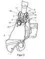
- Figures 2 to 4 show an upper link similar to Figure 1 , but wherein a cardanic universal joint is used for connecting the upper link constituting a first member 3 to the second member 5, again formed by the support structure for an upper link 3 of a front hitch of a vehicle (not shown).
- the first member 3 is connected to the second member or support structure 5 via a coupling member 7.
- the first member 3 is provided with a lug 4 at its end adjacent the coupling member 7, and this lug 4 is received within a bifurcated first end 71 of the coupling member 7 for pivotal movement about a first axis 10 extending through a pivot pin 72.
- the coupling member 7 has a second end opposite to the first bifurcated end, the second end being provided with a lug 73 received within the bifurcated end 51 of the second member or support structure for pivotal movement about a second axis 20 extending through a pivot pin 52.
- the embodiment shown in Figures 2 through 4 further comprises a locking arrangement comprising a locking pin 61 which extends through aligned recesses in the free ends of plates forming the bifurcated end 51 of the second member 5 and of the free end of the lug 4 of the first member 3.
- These recesses may be either formed by grooves 53 formed in the edge of the free ends of the plates 51, as well as an elongated groove 74 formed in the free end of the lug 4 of the first member 3, or corresponding bores may extend through these plates 51 and the end of the lug 4 at a position intermediate the first and second pivot axes 10, 20. These recesses or bores are disposed in a manner such that they are aligned in the predetermined desired park position of the first and second members 3, 5, so that, on inserting the locking pin 61, the two members 3, 5 are blocked in this desired park position.
- the locking pin arrangement 6 which comprises the locking pin 61 may be secured in its position by a ring 62 fixed at one end of the locking pin 61 and at least one linchpin 8 insertable at the opposite end of the locking pin 61, so that it may readily be removed on mounting the implement (not shown). It is clear that according to an alternative embodiment the ring 62 could be replaced by a linchpin.
- the support structure forming the second member 5 of the universal joint is shown as bifurcated, it of course would be possible to have a reversed structure, wherein the support structure 5 secured to the vehicle is formed by a lug received by a bifurcated end of a coupling member which itself is provided at its opposite end with a lug received by a bifurcated end of the first member 3.
- the locking pin 61 would extend through aligned recesses at the end of the lug of the second member 5 and the bifurcated end of the first member 3.
Landscapes
- Engineering & Computer Science (AREA)
- Mechanical Engineering (AREA)
- Transportation (AREA)
- Life Sciences & Earth Sciences (AREA)
- Zoology (AREA)
- Soil Sciences (AREA)
- Environmental Sciences (AREA)
- Pivots And Pivotal Connections (AREA)
- Agricultural Machines (AREA)
Abstract
Description
- The present invention relates to an universal joint for connecting a first member and a second member for a pivotal movement about first and second mutually orthogonal axes.
- Such universal joints are used for example as parts of links for coupling different implements to agricultural or industrial vehicles. Such universal joints often include some type of ball joints with limited degree of freedom for pivoting about one of the mutually orthogonal axes.
- With front hitch devices for agricultural or industrial vehicles wherein the front hitch device is mounted to the front axle, the oscillation of the front axle also is transmitted to the implement attached thereto. For handling of the implement, it is advantageous to position this implement with the smallest possible distance to the front axle of the vehicle.
- In view of the continuously stricter environmental requirements it is necessary to better control the motor cooling system (water cooler, charge cooling). Further, additional coolers for the drive train (transmission oil cooler) and the hydraulic components (hydraulic fluid cooler) may be required. With improved working conditions, an air conditioning system is required which needs a condensor. All these coolers should be preferably disposed at the front end of the vehicle.
- In addition to these coolers, today larger head lamps are desired and used adding to the space requirement of the devices disposed at the front of the vehicle.
- All these factors in total have a negative effect to the upper coupling point of the upper or top link of a front hitch device. This upper coupling point is continuously moved in forward direction to accommodate all the devices mentioned. Since the implement in spite of this shall be disposed as near as possible to the vehicle, the length of the upper link is continuously reduced.
- Since the angle of oscillation of the front axle is always the same, this results in an increase of the angle of movement of the upper link relative to the central plane of the vehicle. Therefore, the usability of a conventional upper link with a ball joint eye and bearing ball joint is reduced. In most cases, a cardanic universal joint is required.
- The same applies to any coupling means between vehicle and an implement as far as such coupling means include a joint subject to a movement exceeding that which may be accommodated by a ball joint.
- If no front implement is used, the position of the upper link is not defined. To avoid undue movements of the upper link, this link may be taken down and brought into a park position. A further possibility is the use of a park position with installed top link. For the user of the vehicle, it would be advantageous to be able to move the upper link into a park position without any dismantling. In this case, the upper link has not to be installed again on subsequently using the front implement.
- For the mounting of the upper link by means of a ball joint eye and bearing ball, there is already a rather simple solution for a park position shown in
Figure 1 . - A first member of the
upper link 1 is blocked by means of a pin 2 extending through theplates 5 of the bifurcated end of the second member of the support arrangement and a lug mounted to the ball joint eye or integrally formed therewith. - With a cardanic universal joint, there is an additional degree of freedom, which has to be taken into account in blocking this joint. All known solutions are quite complicated and expensive and further need space which anyhow is only available in a limited manner.
- An example for a cardanic universal joint having a limited degree of freedom into mutually perpendicular directions is disclosed in
EP 1 982 855 A1 - The object of the present invention is to provide a universal joint which may be blocked in a park position without the requirement of a complicated design and devices which are space consuming and prone to collecting dirt and debris. According to the present invention, an universal joint is provided comprising an elongated coupling member having a longitudinal axis and respective first and second pivot pins adjacent its first and second longitudinal ends for coupling a first member and a second member for a pivotal movement about first and second mutually orthogonal axes extending through the first and second pivot pins, respectively, the first and second mutually orthogonal axes extending perpendicularly to the longitudinal axis of the coupling member, the first member having at its end adjacent the universal joint a lug received within a bifurcated first end of the coupling member for a pivotal movement around the first axis extending through the bifurcated end and the lug, the coupling member having, at its second end opposite to the first end, a lug received within a bifurcated end of the second member for pivotal movement around the second axis extending through the bifurcated end of the second member and the lug of the coupling member; characterized by a locking arrangement for locking the first and second members in a predetermined position against a movement about the respective pivot axes, the locking arrangement comprising:
- a first elongated recess at the free distal end of the lug of the first member, the recess extending substantially parallel to the second pivot axis at a position intermediate the first and second pivot axes;
- second recesses at the free ends of laterally disposed plates forming the bifurcated end of the second member, the second recesses being aligned with the first recess in the predetermined position; and
- a locking pin insertable through the first and second recesses in the predetermined aligned position thereof for locking the first and second members against any relative motion.
- The recesses may be formed by holes extending through the links of the forked second or support member and the end of the first member of the upper link, or these recesses may simply be indented into the end surfaces of the plates of the forked support block and the end of the lug of the first member.
- According to a preferred embodiment, the clearance between the pin and the recesses is as small as possible to avoid undue vibrations of the universal joint if blocked in the parking position.
- The present invention will be explained in detail on the base of the enclosed drawings wherein:
- Figure 1
- shows a known embodiment of a locking arrangement for a ball eye and bearing ball arrangement.
- Figure 2
- shows a perspective view of a first embodiment of the present invention.
- Figure 3
- is a side view of the locking arrangement of the universal joint of
Figure 2 . - Figure 4
- shows a detail of the locking arrangement in greater scale.
- In spite of the fact that the present invention in the following will be explained in detail referring to the upper link of a front hitch device for mounting implements to an agricultural or industrial vehicle, the principles of locking such universal joint are applicable for any universal joint of the type defined in the preamble of
claim 1. -
Figure 1 shows a version of a known locking arrangement for a ball joint arrangement which has been used for mounting the upper link of a front hitch device to an implement. The arrangement shown inFigure 1 comprises theupper link 1 of such a device which is mounted to asupport structure 5 of a vehicle via a ball joint eye fixed to the end of theupper link 1, the ball joint eye receiving a ball joint journaled on apin 5A mounted on the bifurcated end of thesecond member 5 of the universal joint constituted by the support mounted on the vehicle. - For enabling the locking of the
upper link 1 in the non-used stage, the ball joint eye is provided with a lug having a bore extending there through and aligned with corresponding bores in the two plates of thesecond member 5 in an aligned stage corresponding to the desired locking position. A locking pin 2 may be inserted into the aligned bores in thesecond member 5 and the lug of the ball joint eye to lock theupper link 1 in the predetermined position since on inserting the locking pin 2, theupper link 1 may neither pivot around theaxis 5A nor swivel about the ball joint about axes perpendicular to the axis of thepin 5A. - As indicated above, such ball joint arrangements only have a limited degree of freedom so that, if used for instance for mounting the
upper link 1 to a support structure on a vehicle having an axle mounted front hitch, such an arrangement may not be used if the upper link is rather short and the deflection thereof is rather large. - In such cases, therefore, cardanic universal joints have to be used which provide a larger possible angle of deflection between the two members to be coupled thereby.
-
Figures 2 to 4 show an upper link similar toFigure 1 , but wherein a cardanic universal joint is used for connecting the upper link constituting afirst member 3 to thesecond member 5, again formed by the support structure for anupper link 3 of a front hitch of a vehicle (not shown). - With the embodiment of the universal joint shown in
Figures 2 through 4 , thefirst member 3 is connected to the second member orsupport structure 5 via acoupling member 7. For this purpose, thefirst member 3 is provided with alug 4 at its end adjacent thecoupling member 7, and thislug 4 is received within a bifurcatedfirst end 71 of thecoupling member 7 for pivotal movement about afirst axis 10 extending through apivot pin 72. - The
coupling member 7 has a second end opposite to the first bifurcated end, the second end being provided with alug 73 received within the bifurcatedend 51 of the second member or support structure for pivotal movement about asecond axis 20 extending through apivot pin 52. - The embodiment shown in
Figures 2 through 4 further comprises a locking arrangement comprising alocking pin 61 which extends through aligned recesses in the free ends of plates forming the bifurcatedend 51 of thesecond member 5 and of the free end of thelug 4 of thefirst member 3. - These recesses may be either formed by
grooves 53 formed in the edge of the free ends of theplates 51, as well as anelongated groove 74 formed in the free end of thelug 4 of thefirst member 3, or corresponding bores may extend through theseplates 51 and the end of thelug 4 at a position intermediate the first andsecond pivot axes second members locking pin 61, the twomembers - The
locking pin arrangement 6 which comprises thelocking pin 61 may be secured in its position by aring 62 fixed at one end of thelocking pin 61 and at least onelinchpin 8 insertable at the opposite end of thelocking pin 61, so that it may readily be removed on mounting the implement (not shown). It is clear that according to an alternative embodiment thering 62 could be replaced by a linchpin. - In spite of the fact that with the embodiment shown in
Figures 2 through 4 , the support structure forming thesecond member 5 of the universal joint is shown as bifurcated, it of course would be possible to have a reversed structure, wherein thesupport structure 5 secured to the vehicle is formed by a lug received by a bifurcated end of a coupling member which itself is provided at its opposite end with a lug received by a bifurcated end of thefirst member 3. - In the last mentioned version (not shown), the
locking pin 61 would extend through aligned recesses at the end of the lug of thesecond member 5 and the bifurcated end of thefirst member 3.
Claims (6)
- Universal joint comprising an elongated coupling member (7) having a longitudinal axis and respective first and second pivot pins (72, 52) adjacent its first and second longitudinal ends for coupling a first member (3) and a second member (5) for a pivotal movement about first and second mutually orthogonal axes (10, 20) extending through the first and second pivot pins (72, 52), respectively, the first and second mutually orthogonal axes (10, 20) extending perpendicularly to the longitudinal axis of the coupling member (7), the first member (3) having at its end adjacent the universal joint a lug (4) received within a bifurcated first end (71) of the coupling member (7) for a pivotal movement around the first axis (10) extending through the bifurcated end (71) and the lug (4), the coupling member (7) having, at its second end opposite to the first end, a lug (73) received within a bifurcated end (51) of the second member (5) for pivotal movement around the second axis (20) extending through the bifurcated end of the second member (5) and the lug (73) of the coupling member;
characterized by a locking arrangement for locking the first and second members (3, 5) in a predetermined position against a movement about the respective pivot axes (10, 20), the locking arrangement comprising:a first elongated recess (74) at the free distal end of the lug (4) of the first member (3), the recess (74) extending substantially parallel to the second pivot axis (20) at a position intermediate the first and second pivot axes (10, 20);second recesses (53) at the free ends of laterally disposed plates (51) forming the bifurcated end of the second member (5), the second recesses (53) being aligned with the first recess (74) in the predetermined position; anda locking pin (61) insertable through the first and second recesses (74, 53) in the predetermined aligned position thereof for locking the first and second members (3, 5) against any relative motion. - Universal joint according to claim 1, characterized in that the first recess (74) is formed by a groove in the free end of the lug (4) of the first member (3), the groove having a longitudinal extension substantially perpendicular to the first axis.
- Universal joint according to claim 1, characterized in that the first recess is formed by a bore extending through the free distal end of the lug (4) of the first member (3) substantially perpendicular to the first axis (10).
- Universal joint according to any of the claim 1 to 3, characterized in that the second recesses (53) at the free ends of laterally disposed plates (51 ) forming the bifurcated end of the second member (5) are formed by bores extending through the plates (51) at a position intermediate the first and second pivot axes (10, 20)
- Universal joint according to any of the preceding claims, characterized in that the locking pin (61) inserted through the first and second recesses (74, 53) in the predetermined aligned position thereof is secured in place by at least one linchpin (8).
- Universal joint according to any of the preceding claims, characterized in that the first member (3) is the upper link of a front hitch of a vehicle and that the second member (5) is mounted to a hitch support structure of the vehicle.
Applications Claiming Priority (1)
| Application Number | Priority Date | Filing Date | Title |
|---|---|---|---|
| BE2009/0433A BE1018826A3 (en) | 2009-07-16 | 2009-07-16 | AN IMPROVED UNIVERSAL COUPLING. |
Publications (2)
| Publication Number | Publication Date |
|---|---|
| EP2274967A1 true EP2274967A1 (en) | 2011-01-19 |
| EP2274967B1 EP2274967B1 (en) | 2012-07-04 |
Family
ID=41718839
Family Applications (1)
| Application Number | Title | Priority Date | Filing Date |
|---|---|---|---|
| EP20100169731 Active EP2274967B1 (en) | 2009-07-16 | 2010-07-15 | Improved universal joint |
Country Status (2)
| Country | Link |
|---|---|
| EP (1) | EP2274967B1 (en) |
| BE (1) | BE1018826A3 (en) |
Cited By (1)
| Publication number | Priority date | Publication date | Assignee | Title |
|---|---|---|---|---|
| US20230030953A1 (en) * | 2021-08-02 | 2023-02-02 | Cnh Industrial America Llc | Quick storage cradle for combine multicoupler |
Families Citing this family (6)
| Publication number | Priority date | Publication date | Assignee | Title |
|---|---|---|---|---|
| EP3379222B1 (en) | 2017-03-22 | 2020-12-30 | Methode Electronics Malta Ltd. | Magnetoelastic based sensor assembly |
| US11135882B2 (en) | 2018-02-27 | 2021-10-05 | Methode Electronics, Inc. | Towing systems and methods using magnetic field sensing |
| US11084342B2 (en) | 2018-02-27 | 2021-08-10 | Methode Electronics, Inc. | Towing systems and methods using magnetic field sensing |
| US11221262B2 (en) | 2018-02-27 | 2022-01-11 | Methode Electronics, Inc. | Towing systems and methods using magnetic field sensing |
| EP3758959B1 (en) | 2018-02-27 | 2025-11-05 | Methode Electronics, Inc. | Towing systems and methods using magnetic field sensing |
| US11491832B2 (en) | 2018-02-27 | 2022-11-08 | Methode Electronics, Inc. | Towing systems and methods using magnetic field sensing |
Citations (5)
| Publication number | Priority date | Publication date | Assignee | Title |
|---|---|---|---|---|
| EP0065081A1 (en) * | 1981-05-15 | 1982-11-24 | Klöckner-Humboldt-Deutz Aktiengesellschaft | Implement attaching structure for a tractor |
| DE3643209A1 (en) * | 1986-12-18 | 1988-06-30 | Hans Dipl Ing Goebel | Connection of the upper link of a three-point mounting device of tractors for agriculture, forestry and commerce |
| DE3839522C1 (en) * | 1988-11-23 | 1989-11-30 | J I Case Gmbh, 4040 Neuss, De | Device for fixing the unused upper link of a hydraulic three-point mounting apparatus on farm tractors |
| DE4129908C1 (en) * | 1991-09-09 | 1993-01-28 | J I Case Gmbh, 4040 Neuss, De | Hitch point mounting on tractor - includes pin plugging into bores in holder fitting |
| EP1982855A1 (en) | 2007-04-20 | 2008-10-22 | Deere & Company | Linkage device for a three-point trailer coupler |
-
2009
- 2009-07-16 BE BE2009/0433A patent/BE1018826A3/en not_active IP Right Cessation
-
2010
- 2010-07-15 EP EP20100169731 patent/EP2274967B1/en active Active
Patent Citations (5)
| Publication number | Priority date | Publication date | Assignee | Title |
|---|---|---|---|---|
| EP0065081A1 (en) * | 1981-05-15 | 1982-11-24 | Klöckner-Humboldt-Deutz Aktiengesellschaft | Implement attaching structure for a tractor |
| DE3643209A1 (en) * | 1986-12-18 | 1988-06-30 | Hans Dipl Ing Goebel | Connection of the upper link of a three-point mounting device of tractors for agriculture, forestry and commerce |
| DE3839522C1 (en) * | 1988-11-23 | 1989-11-30 | J I Case Gmbh, 4040 Neuss, De | Device for fixing the unused upper link of a hydraulic three-point mounting apparatus on farm tractors |
| DE4129908C1 (en) * | 1991-09-09 | 1993-01-28 | J I Case Gmbh, 4040 Neuss, De | Hitch point mounting on tractor - includes pin plugging into bores in holder fitting |
| EP1982855A1 (en) | 2007-04-20 | 2008-10-22 | Deere & Company | Linkage device for a three-point trailer coupler |
Cited By (2)
| Publication number | Priority date | Publication date | Assignee | Title |
|---|---|---|---|---|
| US20230030953A1 (en) * | 2021-08-02 | 2023-02-02 | Cnh Industrial America Llc | Quick storage cradle for combine multicoupler |
| US12207593B2 (en) * | 2021-08-02 | 2025-01-28 | Cnh Industrial America Llc | Quick storage cradle for combine multicoupler |
Also Published As
| Publication number | Publication date |
|---|---|
| EP2274967B1 (en) | 2012-07-04 |
| BE1018826A3 (en) | 2011-09-06 |
Similar Documents
| Publication | Publication Date | Title |
|---|---|---|
| EP2274967B1 (en) | Improved universal joint | |
| RU2562091C2 (en) | Independent suspension for spring-loaded controlled wheel | |
| US6877758B2 (en) | Pivoting implement hitch extension | |
| US9079610B2 (en) | Telescopic device of steering column for vehicle | |
| US8061438B2 (en) | Hand-held power tool with a vibration-damped handle | |
| US9464663B2 (en) | Ball joint | |
| EP2558399A1 (en) | Arrangement related to guiding of hoses and/or cables | |
| AU2013276799B2 (en) | Steering arrangement | |
| CN101415526A (en) | Portable power tool with vibration-damped handle | |
| EP2995725A1 (en) | Quick coupler for coupling a hydraulically operated tool/implement onto an excavator and a mechanical coupling member | |
| KR20000019841A (en) | Device for exchanging work equipment of excavator | |
| JP4299182B2 (en) | Body connecting method and apparatus | |
| KR100766522B1 (en) | Power train using variable transmission shaft | |
| CN210634566U (en) | Coupling device for connecting two carriages | |
| CA2742082A1 (en) | Position adjustable coupler and hitch equipped therewith | |
| CN101363480A (en) | Pivoting structure of universal joint | |
| KR100860449B1 (en) | Traction articulated joints for tractor implements | |
| CN111608220B (en) | Loader accessory coupler | |
| US6547028B1 (en) | Axle mounting arrangement | |
| CN211764740U (en) | Connecting hook and trailer with same | |
| CN109910532B (en) | Traction mechanism of self-walking vehicle and self-walking vehicle | |
| JP5221506B2 (en) | Tractor | |
| CA2355145C (en) | Improvements to steering tie rod end | |
| US20190063569A1 (en) | Turnbuckle | |
| GB2551319A (en) | Hitch assembly for articulated machine |
Legal Events
| Date | Code | Title | Description |
|---|---|---|---|
| PUAI | Public reference made under article 153(3) epc to a published international application that has entered the european phase |
Free format text: ORIGINAL CODE: 0009012 |
|
| AK | Designated contracting states |
Kind code of ref document: A1 Designated state(s): AL AT BE BG CH CY CZ DE DK EE ES FI FR GB GR HR HU IE IS IT LI LT LU LV MC MK MT NL NO PL PT RO SE SI SK SM TR |
|
| AX | Request for extension of the european patent |
Extension state: BA ME RS |
|
| 17P | Request for examination filed |
Effective date: 20110719 |
|
| GRAP | Despatch of communication of intention to grant a patent |
Free format text: ORIGINAL CODE: EPIDOSNIGR1 |
|
| RIC1 | Information provided on ipc code assigned before grant |
Ipc: B60D 1/145 20060101ALI20111222BHEP Ipc: B60D 1/02 20060101ALI20111222BHEP Ipc: B60D 1/14 20060101ALI20111222BHEP Ipc: A01B 59/00 20060101AFI20111222BHEP |
|
| GRAS | Grant fee paid |
Free format text: ORIGINAL CODE: EPIDOSNIGR3 |
|
| GRAA | (expected) grant |
Free format text: ORIGINAL CODE: 0009210 |
|
| AK | Designated contracting states |
Kind code of ref document: B1 Designated state(s): AL AT BE BG CH CY CZ DE DK EE ES FI FR GB GR HR HU IE IS IT LI LT LU LV MC MK MT NL NO PL PT RO SE SI SK SM TR |
|
| REG | Reference to a national code |
Ref country code: GB Ref legal event code: FG4D |
|
| REG | Reference to a national code |
Ref country code: CH Ref legal event code: EP |
|
| REG | Reference to a national code |
Ref country code: AT Ref legal event code: REF Ref document number: 564751 Country of ref document: AT Kind code of ref document: T Effective date: 20120715 |
|
| REG | Reference to a national code |
Ref country code: IE Ref legal event code: FG4D |
|
| REG | Reference to a national code |
Ref country code: DE Ref legal event code: R096 Ref document number: 602010002085 Country of ref document: DE Effective date: 20120830 |
|
| REG | Reference to a national code |
Ref country code: NL Ref legal event code: VDEP Effective date: 20120704 |
|
| PG25 | Lapsed in a contracting state [announced via postgrant information from national office to epo] |
Ref country code: SI Free format text: LAPSE BECAUSE OF FAILURE TO SUBMIT A TRANSLATION OF THE DESCRIPTION OR TO PAY THE FEE WITHIN THE PRESCRIBED TIME-LIMIT Effective date: 20120704 |
|
| REG | Reference to a national code |
Ref country code: LT Ref legal event code: MG4D Effective date: 20120704 |
|
| PG25 | Lapsed in a contracting state [announced via postgrant information from national office to epo] |
Ref country code: BE Free format text: LAPSE BECAUSE OF FAILURE TO SUBMIT A TRANSLATION OF THE DESCRIPTION OR TO PAY THE FEE WITHIN THE PRESCRIBED TIME-LIMIT Effective date: 20120704 Ref country code: NO Free format text: LAPSE BECAUSE OF FAILURE TO SUBMIT A TRANSLATION OF THE DESCRIPTION OR TO PAY THE FEE WITHIN THE PRESCRIBED TIME-LIMIT Effective date: 20121004 Ref country code: IS Free format text: LAPSE BECAUSE OF FAILURE TO SUBMIT A TRANSLATION OF THE DESCRIPTION OR TO PAY THE FEE WITHIN THE PRESCRIBED TIME-LIMIT Effective date: 20121104 Ref country code: LT Free format text: LAPSE BECAUSE OF FAILURE TO SUBMIT A TRANSLATION OF THE DESCRIPTION OR TO PAY THE FEE WITHIN THE PRESCRIBED TIME-LIMIT Effective date: 20120704 Ref country code: FI Free format text: LAPSE BECAUSE OF FAILURE TO SUBMIT A TRANSLATION OF THE DESCRIPTION OR TO PAY THE FEE WITHIN THE PRESCRIBED TIME-LIMIT Effective date: 20120704 Ref country code: HR Free format text: LAPSE BECAUSE OF FAILURE TO SUBMIT A TRANSLATION OF THE DESCRIPTION OR TO PAY THE FEE WITHIN THE PRESCRIBED TIME-LIMIT Effective date: 20120704 Ref country code: CY Free format text: LAPSE BECAUSE OF FAILURE TO SUBMIT A TRANSLATION OF THE DESCRIPTION OR TO PAY THE FEE WITHIN THE PRESCRIBED TIME-LIMIT Effective date: 20120704 |
|
| PG25 | Lapsed in a contracting state [announced via postgrant information from national office to epo] |
Ref country code: MK Free format text: LAPSE BECAUSE OF FAILURE TO SUBMIT A TRANSLATION OF THE DESCRIPTION OR TO PAY THE FEE WITHIN THE PRESCRIBED TIME-LIMIT Effective date: 20120704 Ref country code: GR Free format text: LAPSE BECAUSE OF FAILURE TO SUBMIT A TRANSLATION OF THE DESCRIPTION OR TO PAY THE FEE WITHIN THE PRESCRIBED TIME-LIMIT Effective date: 20121005 Ref country code: LV Free format text: LAPSE BECAUSE OF FAILURE TO SUBMIT A TRANSLATION OF THE DESCRIPTION OR TO PAY THE FEE WITHIN THE PRESCRIBED TIME-LIMIT Effective date: 20120704 Ref country code: PL Free format text: LAPSE BECAUSE OF FAILURE TO SUBMIT A TRANSLATION OF THE DESCRIPTION OR TO PAY THE FEE WITHIN THE PRESCRIBED TIME-LIMIT Effective date: 20120704 Ref country code: MC Free format text: LAPSE BECAUSE OF NON-PAYMENT OF DUE FEES Effective date: 20120731 Ref country code: PT Free format text: LAPSE BECAUSE OF FAILURE TO SUBMIT A TRANSLATION OF THE DESCRIPTION OR TO PAY THE FEE WITHIN THE PRESCRIBED TIME-LIMIT Effective date: 20121105 Ref country code: SE Free format text: LAPSE BECAUSE OF FAILURE TO SUBMIT A TRANSLATION OF THE DESCRIPTION OR TO PAY THE FEE WITHIN THE PRESCRIBED TIME-LIMIT Effective date: 20120704 |
|
| PG25 | Lapsed in a contracting state [announced via postgrant information from national office to epo] |
Ref country code: NL Free format text: LAPSE BECAUSE OF FAILURE TO SUBMIT A TRANSLATION OF THE DESCRIPTION OR TO PAY THE FEE WITHIN THE PRESCRIBED TIME-LIMIT Effective date: 20120704 |
|
| PG25 | Lapsed in a contracting state [announced via postgrant information from national office to epo] |
Ref country code: ES Free format text: LAPSE BECAUSE OF FAILURE TO SUBMIT A TRANSLATION OF THE DESCRIPTION OR TO PAY THE FEE WITHIN THE PRESCRIBED TIME-LIMIT Effective date: 20121015 Ref country code: DK Free format text: LAPSE BECAUSE OF FAILURE TO SUBMIT A TRANSLATION OF THE DESCRIPTION OR TO PAY THE FEE WITHIN THE PRESCRIBED TIME-LIMIT Effective date: 20120704 Ref country code: RO Free format text: LAPSE BECAUSE OF FAILURE TO SUBMIT A TRANSLATION OF THE DESCRIPTION OR TO PAY THE FEE WITHIN THE PRESCRIBED TIME-LIMIT Effective date: 20120704 Ref country code: CZ Free format text: LAPSE BECAUSE OF FAILURE TO SUBMIT A TRANSLATION OF THE DESCRIPTION OR TO PAY THE FEE WITHIN THE PRESCRIBED TIME-LIMIT Effective date: 20120704 Ref country code: EE Free format text: LAPSE BECAUSE OF FAILURE TO SUBMIT A TRANSLATION OF THE DESCRIPTION OR TO PAY THE FEE WITHIN THE PRESCRIBED TIME-LIMIT Effective date: 20120704 |
|
| REG | Reference to a national code |
Ref country code: IE Ref legal event code: MM4A |
|
| PLBE | No opposition filed within time limit |
Free format text: ORIGINAL CODE: 0009261 |
|
| STAA | Information on the status of an ep patent application or granted ep patent |
Free format text: STATUS: NO OPPOSITION FILED WITHIN TIME LIMIT |
|
| PG25 | Lapsed in a contracting state [announced via postgrant information from national office to epo] |
Ref country code: SK Free format text: LAPSE BECAUSE OF FAILURE TO SUBMIT A TRANSLATION OF THE DESCRIPTION OR TO PAY THE FEE WITHIN THE PRESCRIBED TIME-LIMIT Effective date: 20120704 |
|
| 26N | No opposition filed |
Effective date: 20130405 |
|
| PG25 | Lapsed in a contracting state [announced via postgrant information from national office to epo] |
Ref country code: BG Free format text: LAPSE BECAUSE OF FAILURE TO SUBMIT A TRANSLATION OF THE DESCRIPTION OR TO PAY THE FEE WITHIN THE PRESCRIBED TIME-LIMIT Effective date: 20121004 Ref country code: MT Free format text: LAPSE BECAUSE OF FAILURE TO SUBMIT A TRANSLATION OF THE DESCRIPTION OR TO PAY THE FEE WITHIN THE PRESCRIBED TIME-LIMIT Effective date: 20120704 Ref country code: IE Free format text: LAPSE BECAUSE OF NON-PAYMENT OF DUE FEES Effective date: 20120715 |
|
| REG | Reference to a national code |
Ref country code: DE Ref legal event code: R097 Ref document number: 602010002085 Country of ref document: DE Effective date: 20130405 |
|
| PG25 | Lapsed in a contracting state [announced via postgrant information from national office to epo] |
Ref country code: AL Free format text: LAPSE BECAUSE OF FAILURE TO SUBMIT A TRANSLATION OF THE DESCRIPTION OR TO PAY THE FEE WITHIN THE PRESCRIBED TIME-LIMIT Effective date: 20120704 |
|
| REG | Reference to a national code |
Ref country code: DE Ref legal event code: R082 Ref document number: 602010002085 Country of ref document: DE Representative=s name: PATENTANWAELTE WALLACH, KOCH & PARTNER, DE |
|
| PG25 | Lapsed in a contracting state [announced via postgrant information from national office to epo] |
Ref country code: TR Free format text: LAPSE BECAUSE OF FAILURE TO SUBMIT A TRANSLATION OF THE DESCRIPTION OR TO PAY THE FEE WITHIN THE PRESCRIBED TIME-LIMIT Effective date: 20120704 |
|
| REG | Reference to a national code |
Ref country code: DE Ref legal event code: R082 Ref document number: 602010002085 Country of ref document: DE Representative=s name: PATENTANWAELTE WALLACH, KOCH, DR. HAIBACH, FEL, DE Effective date: 20140422 Ref country code: DE Ref legal event code: R082 Ref document number: 602010002085 Country of ref document: DE Representative=s name: PATENTANWAELTE WALLACH, KOCH & PARTNER, DE Effective date: 20140422 Ref country code: DE Ref legal event code: R081 Ref document number: 602010002085 Country of ref document: DE Owner name: CNH INDUSTRIAL OESTERREICH GMBH, AT Free format text: FORMER OWNER: CNH OESTERREICH GMBH, ST. VALENTIN, AT Effective date: 20140422 |
|
| PG25 | Lapsed in a contracting state [announced via postgrant information from national office to epo] |
Ref country code: SM Free format text: LAPSE BECAUSE OF FAILURE TO SUBMIT A TRANSLATION OF THE DESCRIPTION OR TO PAY THE FEE WITHIN THE PRESCRIBED TIME-LIMIT Effective date: 20120704 Ref country code: LU Free format text: LAPSE BECAUSE OF NON-PAYMENT OF DUE FEES Effective date: 20120715 |
|
| PG25 | Lapsed in a contracting state [announced via postgrant information from national office to epo] |
Ref country code: HU Free format text: LAPSE BECAUSE OF FAILURE TO SUBMIT A TRANSLATION OF THE DESCRIPTION OR TO PAY THE FEE WITHIN THE PRESCRIBED TIME-LIMIT Effective date: 20100715 |
|
| REG | Reference to a national code |
Ref country code: CH Ref legal event code: PL |
|
| PG25 | Lapsed in a contracting state [announced via postgrant information from national office to epo] |
Ref country code: CH Free format text: LAPSE BECAUSE OF NON-PAYMENT OF DUE FEES Effective date: 20140731 Ref country code: LI Free format text: LAPSE BECAUSE OF NON-PAYMENT OF DUE FEES Effective date: 20140731 |
|
| REG | Reference to a national code |
Ref country code: FR Ref legal event code: PLFP Year of fee payment: 7 |
|
| REG | Reference to a national code |
Ref country code: FR Ref legal event code: PLFP Year of fee payment: 8 |
|
| PGFP | Annual fee paid to national office [announced via postgrant information from national office to epo] |
Ref country code: AT Payment date: 20170727 Year of fee payment: 8 |
|
| REG | Reference to a national code |
Ref country code: FR Ref legal event code: PLFP Year of fee payment: 9 |
|
| REG | Reference to a national code |
Ref country code: AT Ref legal event code: MM01 Ref document number: 564751 Country of ref document: AT Kind code of ref document: T Effective date: 20180715 |
|
| PG25 | Lapsed in a contracting state [announced via postgrant information from national office to epo] |
Ref country code: AT Free format text: LAPSE BECAUSE OF NON-PAYMENT OF DUE FEES Effective date: 20180715 |
|
| PGFP | Annual fee paid to national office [announced via postgrant information from national office to epo] |
Ref country code: GB Payment date: 20190724 Year of fee payment: 10 |
|
| GBPC | Gb: european patent ceased through non-payment of renewal fee |
Effective date: 20200715 |
|
| PG25 | Lapsed in a contracting state [announced via postgrant information from national office to epo] |
Ref country code: GB Free format text: LAPSE BECAUSE OF NON-PAYMENT OF DUE FEES Effective date: 20200715 |
|
| REG | Reference to a national code |
Ref country code: DE Ref legal event code: R082 Ref document number: 602010002085 Country of ref document: DE Representative=s name: MEISSNER BOLTE PATENTANWAELTE RECHTSANWAELTE P, DE |
|
| PGFP | Annual fee paid to national office [announced via postgrant information from national office to epo] |
Ref country code: FR Payment date: 20240724 Year of fee payment: 15 |
|
| PGFP | Annual fee paid to national office [announced via postgrant information from national office to epo] |
Ref country code: IT Payment date: 20240709 Year of fee payment: 15 |
|
| PGFP | Annual fee paid to national office [announced via postgrant information from national office to epo] |
Ref country code: DE Payment date: 20250728 Year of fee payment: 16 |
|
| PG25 | Lapsed in a contracting state [announced via postgrant information from national office to epo] |
Ref country code: FR Free format text: LAPSE BECAUSE OF NON-PAYMENT OF DUE FEES Effective date: 20250731 |