EP2274937B1 - Power save mechanism for wireless communication devices - Google Patents
Power save mechanism for wireless communication devices Download PDFInfo
- Publication number
- EP2274937B1 EP2274937B1 EP09742528.4A EP09742528A EP2274937B1 EP 2274937 B1 EP2274937 B1 EP 2274937B1 EP 09742528 A EP09742528 A EP 09742528A EP 2274937 B1 EP2274937 B1 EP 2274937B1
- Authority
- EP
- European Patent Office
- Prior art keywords
- mobile wireless
- wireless device
- peer mobile
- transmitting
- data transfer
- Prior art date
- Legal status (The legal status is an assumption and is not a legal conclusion. Google has not performed a legal analysis and makes no representation as to the accuracy of the status listed.)
- Active
Links
Images










Classifications
-
- H—ELECTRICITY
- H04—ELECTRIC COMMUNICATION TECHNIQUE
- H04W—WIRELESS COMMUNICATION NETWORKS
- H04W52/00—Power management, e.g. Transmission Power Control [TPC] or power classes
- H04W52/02—Power saving arrangements
- H04W52/0209—Power saving arrangements in terminal devices
- H04W52/0212—Power saving arrangements in terminal devices managed by the network, e.g. network or access point is leader and terminal is follower
- H04W52/0219—Power saving arrangements in terminal devices managed by the network, e.g. network or access point is leader and terminal is follower where the power saving management affects multiple terminals
-
- H—ELECTRICITY
- H04—ELECTRIC COMMUNICATION TECHNIQUE
- H04W—WIRELESS COMMUNICATION NETWORKS
- H04W52/00—Power management, e.g. Transmission Power Control [TPC] or power classes
- H04W52/02—Power saving arrangements
- H04W52/0209—Power saving arrangements in terminal devices
- H04W52/0212—Power saving arrangements in terminal devices managed by the network, e.g. network or access point is leader and terminal is follower
- H04W52/0216—Power saving arrangements in terminal devices managed by the network, e.g. network or access point is leader and terminal is follower using a pre-established activity schedule, e.g. traffic indication frame
-
- H—ELECTRICITY
- H04—ELECTRIC COMMUNICATION TECHNIQUE
- H04W—WIRELESS COMMUNICATION NETWORKS
- H04W76/00—Connection management
- H04W76/10—Connection setup
- H04W76/14—Direct-mode setup
-
- H—ELECTRICITY
- H04—ELECTRIC COMMUNICATION TECHNIQUE
- H04W—WIRELESS COMMUNICATION NETWORKS
- H04W74/00—Wireless channel access
- H04W74/04—Scheduled access
-
- Y—GENERAL TAGGING OF NEW TECHNOLOGICAL DEVELOPMENTS; GENERAL TAGGING OF CROSS-SECTIONAL TECHNOLOGIES SPANNING OVER SEVERAL SECTIONS OF THE IPC; TECHNICAL SUBJECTS COVERED BY FORMER USPC CROSS-REFERENCE ART COLLECTIONS [XRACs] AND DIGESTS
- Y02—TECHNOLOGIES OR APPLICATIONS FOR MITIGATION OR ADAPTATION AGAINST CLIMATE CHANGE
- Y02D—CLIMATE CHANGE MITIGATION TECHNOLOGIES IN INFORMATION AND COMMUNICATION TECHNOLOGIES [ICT], I.E. INFORMATION AND COMMUNICATION TECHNOLOGIES AIMING AT THE REDUCTION OF THEIR OWN ENERGY USE
- Y02D30/00—Reducing energy consumption in communication networks
- Y02D30/70—Reducing energy consumption in communication networks in wireless communication networks
Definitions
- the field of the invention relates to wireless communication and more particularly to power saving in wireless communication devices.
- GSM Global System for Mobile Communications
- WCD wireless communications device
- ISDN Integrated Services Digital Network
- POTS Plain Old Telephone Service
- MMS Multimedia Messaging Service
- DVB-H Digital Video Broadcasting for Handheld Devices
- Bluetooth TM is an example of a short-range wireless technology quickly gaining acceptance in the marketplace.
- a 1 Mbps Bluetooth TM radio may transmit and receive data at a rate of 720 Kbps within a range of 10 meters, and may transmit up to 100 meters with additional power boosting.
- Enhanced Data Rate (EDR) technology which is also available, may enable maximum asymmetric data rates of 1448 Kbps for a 2 Mbps connection and 2178 Kbps for a 3 Mbps connection.
- Bluetooth TM other popular short-range wireless networks include for example IEEE 802.11 Wireless LAN, Wireless Universal Serial Bus (WUSB), Ultra Wideband (UWB), ZigBee (IEEE 802.15.4 and IEEE 802.15.4a), wherein each of these exemplary wireless mediums have features and advantages that make them appropriate for various applications
- the IEEE 802.11 Wireless LAN Standards describe two major components, a mobile wireless device, called a station (STA), and a fixed access point (AP) wireless device.
- the AP may perform the wireless-to-wired bridging from STAs to a wired network.
- the basic network is the basic service set (BSS), which is a group of wireless devices that communicate with each other.
- BSS basic service set
- An infrastructure BSS is a network that has an AP as an essential node.
- the access point (AP) in legacy IEEE 802.11 Wireless LAN networks must relay all communication between the mobile wireless devices (STAs) in an infrastructure BSS. If a STA in an infrastructure BSS wishes to communicate a frame of data to a second STA, the communication must take two hops. First, the originating STA transfers the frame to the AP. Second, the AP transfers the frame to the second STA.
- the access point (AP) in legacy IEEE 802.11 Wireless LAN networks must relay all communication between the mobile wireless devices (STAs) in an infrastructure BSS. If a STA in an infrastructure BSS wishes to communicate a frame of data to a second STA, the communication must take two hops. First, the originating STA transfers the frame to the AP. Second, the AP transfers the frame to the second STA. The access point (AP) in an infrastructure BSS assists those mobile wireless devices (STAs) attempting to save power.
- the legacy IEEE 802.1 Ie Wireless LAN standards provides for support of low power operation in handheld and battery operated STAs, called automatic power save delivery (APSD).
- a STA capable of APSD and currently in the power saving mode will wake up at predetermined beacons received from the AP to listen to a Traffic Indication Map (TIM). If existence of buffered traffic waiting to be sent to the STA is signaled through the TIM, the STA will remain awake until AP sends out all the data. The STA does not need to send a polling signal to the AP to retrieve data, which is the reason for the term "automatic" in the acronym APSD.
- TIM Traffic Indication Map
- U-APSD unscheduled automatic power save delivery
- S-APSD scheduled automatic power save delivery
- U-APSD the access point (AP) is always awake and hence a mobile wireless device (STA) in the power save mode can send a trigger frame to the AP when the STA wakes up, to retrieve any queued data at the AP and also transmit any data queued from the STA to the AP.
- S-APSD the AP assigns a schedule to a STA and the STA wakes up at the assigned time to retrieve from the AP any data queued for the STA.
- An AP can maintain multiple schedules either with the same STA or with different STAs in the infrastructure BSS network. Since the AP is never in sleep mode, an AP will maintain different scheduled periods of transmission with different STAs in the infrastructure BSS network to ensure that the STAs get the maximum power savings.
- a next generation IEEE 802.11 WLAN standard is being currently developed as the IEEE 802.11 TGz standard, which includes the feature of Tunneled Direct Link Setup (TDLS) with Channel Switching.
- TDLS Tunneled Direct Link Setup
- AP access point
- the IEEE 802.11 TGz standard currently under development does not provide means for multiple STAs to enter into a power saving sleep mode, since the AP is no longer available to buffer the frames in the direct data transfer link between the STAs.
- WO2005/069806 discloses a method of providing power management in a Wireless Local Area Network.
- US2007/230418 discloses a method for implementing an unscheduled automatic power save delivery in a Wireless Local Area Network.
- US2005/018624 discloses a power-save QSTA that notifies an access point that it is operating in an automatic power-save delivery mode.
- EP1033832 discloses a wireless communications system operable in a power saving mode.
- US2007/0159992 discloses a power saving device and method for a mobile access point.
- Method, apparatus, and computer program product embodiments are disclosed to enable power save modes of operation between mobile wireless devices for direct data transfer in an infrastructure BSS.
- a first aspect of the invention is set forth in claim 1 of the appended claims.
- a second aspect of the invention is set forth in claim 3 of the appended claims.
- a third aspect of the invention is set forth in claim 8 of the appended claims.
- a fourth aspect of the invention is set forth in claim 13 of the appended claims.
- An example embodiment enables a power save mode operation between the mobile wireless devices for direct data transfer.
- a transmitting mobile wireless device Prior to a transmitting mobile wireless device entering the power save mode, it inserts into a message it transmits to a receiving mobile wireless device, a specified time field to indicate when a next active direct data transfer period will start, so that the devices can remain in power save mode in a direct data transfer link until that time.
- the value of the time field is set to the next "wakeup time".
- the message may be, for example, the last message that is transmitted by the transmitting mobile wireless device in the final frame, for instance where the frame has the End Of Service Period (EOSP) bit set to 1 instead of 0.
- EOSP End Of Service Period
- the message may be sent over the direct data transfer link to the receiving mobile wireless device or alternately, it may be sent through an access point wireless device or any other wireless device to the receiving mobile wireless device.
- the specified time in the message indicates to the receiving device when the two devices may start a next active direct data transfer period, service period or session, for example, to transfer data or to complete an operation between two devices over the direct data transfer link.
- the message may enable both the transmitting and receiving devices to begin a power save mode in the direct data transfer link and to remain in the power save mode until the specified time, when the transmitting device may start transmitting data to the receiving device via the direct data transfer link.
- the receiving device sends a trigger signal based on the specified time indication, the trigger signal indicating that the next period is about to start, so that the transmitting device can start transmitting data to the receiving device via the direct data transfer link.
- the trigger signal may be sent over the direct data transfer link to the transmitting mobile wireless device or alternately, it may be sent through an access point wireless device or any other wireless device to the transmitting mobile wireless device.
- the signaling between the mobile wireless devices enables the devices to enter into and return from the power save mode for a direct data transfer communication link.
- the embodiment enables two mobile wireless devices to share a common view of the time intervals when they need to be available for the beginning of the next active direct data transfer period, service period or session for direct data transfer. Neither of the mobile wireless devices needs to be available all the time, as is necessary in the legacy 802.11 access point (AP). Instead, the mobile wireless devices can directly signal their availability to each other. After that, the two mobile wireless devices handle the next active direct data transfer period, service period or session and complete it.
- AP legacy 802.11 access point
- An example embodiment enables a mobile wireless device in an infrastructure BSS to manage two or more direct data transfer links with two or more other mobile wireless devices in that BSS and coordinate entering into and returning from the power save mode for each direct data transfer link. If one of the mobile wireless devices has data to transmit to each of the other mobile wireless devices, the transmitting device can specify to each receiving device substantially the same starting time when the next active direct data transfer period, service period or session will start, to reduce the number of on/off transitions so as to minimize power consumption.
- a first mobile wireless devices has data to transmit over a first direct data transfer link to a second mobile wireless device and receives an indication of a starting time when it will receive data over a second direct data transfer link from a third mobile wireless device in the infrastructure BSS
- the first mobile wireless device can specify substantially the same starting time to the second mobile wireless device when the next active direct data transfer period, service period or session will start over the first direct data transfer link, to reduce the number of on/off transitions so as to minimize power consumption.
- a mobile wireless device (STA) conducting a service in a direct data transfer link enters the power save mode, it is in a light sleep state.
- the service may be, for example, a session required to transfer data or to complete an operation between two devices over the direct data transfer link.
- the mobile wireless device can go into deep sleep state. Deep sleep indicates that the direct link is inactive, but the credentials for the link between the first and second devices are still valid and hence could be used with the next service. Thus, for the next service between the first and second devices (STAs), no link set up is required and only activation of the direct data transfer link is needed.
- the activation procedure uses the U-APSD packet delivery mechanism between the two mobile wireless devices in the same infrastructure BSS through the access point (AP). For instance, if the second device wants to start a new service with the first device, it sends a traffic indication map (TIM) encapsulated in a data frame to the first device.
- the first step is the second device uses the U-APSD mechanism and sends the encapsulated data to the access point (AP).
- the access point (AP) then performs normal packet delivery to the first device, so the AP indicates in the beacon frame that there is a packet for the first device.
- the first device transmits a poll frame to the AP to retrieve the encapsulated data and after that it sends a trigger frame to the second device over the direct data transfer link to receive the data packets buffered for it in the second device.
- the second device transmits the data packets to the first device over the direct data transfer link.
- the transmitting mobile wireless device may transmit the message initiating the power save modes to the receiving mobile wireless device over a common node path through the access point (AP) or any other wireless station, according to at least one embodiment.
- AP access point
- the receiving STA may send a trigger indication over the common node path to the access point (AP) or any other wireless station, for relaying the trigger indication to the transmitting STA over the common node path to the receiving STA.
- AP access point
- Fig. 1A is an example embodiment network diagram of an exemplary infrastructure BSS network 70, with three mobile wireless devices (STAs) 100A, 100B, and 100C and an access point (AP) 50, which performs wireless-to-wired bridging from the STAs 100A, 100B, and 100C to a wired infrastructure network 60.
- the STAs 100A, 100B, and 100C may operate under the IEEE 802.11 TGz WLAN standard, which includes the feature of Direct Link Setup (DLS).
- DLS enables the STAs 100A, 100B, and 100C in the infrastructure BSS 70 to directly exchange frames of data over a direct data transfer link, without requiring the access point (AP) 50 in the infrastructure BSS to relay the frames.
- DLS Direct Link Setup
- FIG. 1A shows the STAs 100A and 100B directly exchanging frames of data 120AB and 120BA over the direct data transfer link 110 according to the IEEE 802.11 TGz WLAN standard.
- the access point (AP) 50 can, for example, operate under a legacy WLAN standard, such as the IEEE 802.11e Wireless LAN standard according to at least one embodiment.
- Fig. 1A shows the STA 100C and the AP 50 exchanging frames of data 130DC and 130CD in accordance with the IEEE 802.11e WLAN standard.
- the access point (AP) 50 can also relay communications between the mobile wireless devices (STAs) 100A, 100B, and 100C in the infrastructure BSS 70.
- Fig. 1B illustrates an example embodiment of the initiation of a power save mode of operation between the STAs 100A and 100B over the direct data transfer link 110 according to at least one embodiment.
- This example embodiment is applicable to method, apparatus and computer program products.
- the transmitting mobile wireless device STA 100A Prior to the transmitting mobile wireless device STA 100A entering the power save mode, it inserts into a message in frame 120AB that it transmits to the receiving mobile wireless device STA 100B, a specified time field 126 to indicate when a next active direct data transfer period will start, so that the devices STA 100A and STA 100B can remain in power save mode in the direct data transfer link 110 until that time.
- the value of the time field 126 is set to the next "wakeup time".
- the message may be, for example, the last message that is transmitted by the transmitting mobile wireless device in the final frame, for instance where the frame has the End Of Service Period (EOSP) bit set to 1 instead of 0.
- EOSP End Of Service Period
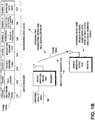
- FIG 1B shows the message frame 120AB that the transmitting STA 100A may transmit, for example, in a last message frame of an active direct data transfer period, service period or session on the direct data transfer link 110, indicating in field 125 that it intends to begin the power save or sleep mode.
- the active direct data transfer period, service period or session may be, for example, the duration of a session required to transfer data or to complete an operation between two devices over the direct data transfer link.
- the example embodiment of FIG 1B shows the transmitting STA 100A is expecting to have data 102 to be transmitted to the receiving STA 100B.
- FIG 1B shows the transmitting STA 100A inserting in the last message frame 120AB according to an embodiment, a specified time 126 when the next active direct data transfer period, service period or session will start and the expected data rate 127, which will enable the receiving STA 100B to decide whether it wants to coordinate beginning of its power save mode for the same time as the transmitting STA 100A and coordinate remaining in the power save mode until that specified time 126 occurs, when both STAs 100A and 100B should be awake. In this manner STA 100A and STA 100B may coordinate entering into and returning from the power save mode over the direct data transfer link.
- FIG 1B shows an example of the last message frame 120AB as a MAC frame including a header portion and an address and data portion.
- the example header portion may include a field 121 indicating that the frame is a data frame and a field 122 that indicates it is a Tunneled Direct Link Setup (TDLS) packet.
- TDLS Tunneled Direct Link Setup
- the example addresses 123 and 124 indicate the transmitting STA 100A and receiving STA 100B.
- the example fields 125, 126, and 127 indicate the next power mode, the specified time when the next active direct data transfer period, service period or session will start, and the expected data rate, respectively. It should be noted that the Fig. 1B is only an example and other frame formats may be used without departing the scope of the present invention. Further, it should be noted that the present application is not intended to be limited only to embodiments where the last message frame includes the indications relating to power save mode of direct data transfer link 110.
- the value in the time field 126 may be signaled in units of the Time Unit (TU), which is used to indicate a unit of time equal to 1024 microseconds.
- the value in the time field 126 is specified relative to the Timing Synchronization Function (TSF) transmitted in the last beacon from the access point (AP) 50.
- TSF Timing Synchronization Function
- IBSS Independent Basic Service Set
- Ad-hoc network the time field 126 is specified relative to the TSF in the last beacon.
- the TSF of the access point (AP) 50 in the common band they share with the AP is used.
- the transmitting STA 100A and the receiving STA 100B may agree in a handshaking protocol over:
- the transmitting STA 100A and the receiving STA 100B after agreeing on a common wakeup time interval, may only send updates to that time if it is going to be changed. No signaling is required if wakeup time is not changing from established time. Hence, support for periodic power save schedule can be provided.
- a handshake protocol conducted by the transmitting STA 100A and the receiving STA 100B over either the common node path 115 through the AP or direct path when creating or activating the direct data transfer link 110 may negotiate the starting instant of the first "wakeup time", the duration of the power save and awake intervals.
- the common node path 115 is a data transfer path that includes the access point 50 or any other wireless station.
- the start time of the next active direct data transfer period, service period or session may be calculated by the transmitting STA 100A in the following manner:
- Some of the constraints based on which transmitting STA 100A picks the start time may include :
- t1 be the minimum time of next data reception by the transmitting STA 100A (referred to here as the transmitter T) and t2 be the time of the start of the next service period (but not yet signaled)
- the following conditions may be used to determine the start time of the next transmission by the transmitting STA 100A according to at least one embodiment:
- This condition insures that the transmitting STA 100A is not busy transmitting data to its receivers, until the expiration of its data reception time (t1 + data reception time by STA 100A).
- the transmitting STA 100A having multiple direct links with receiver stations may overlap corresponding service periods towards different receivers in order to provide:
- the power save states of the transmitting STA 100A and the receiving STA 100B in the direct data transfer link 110 are readily aligned with the power save states required by the access point (AP) 50, since the direct data transfer link 110 is operated in the same frequency channel as the infrastructure BSS 70. In other embodiments where the direct data transfer link 110 may be operated in a different frequency channel from that of the infrastructure BSS 70, alignment of the power save states for the direct data transfer link 110 might be performed only when both STA 100A and STA 100B are in power save mode for the AP.
- Fig. 1C is an example embodiment network diagram of the infrastructure BSS network 70 of Fig. 1A , showing both the transmitting STA 100A and the receiving STA 100B in the power save mode over the direct data transfer link 110.
- the STAs 100A and 100B may be in the sleep mode with respect to the direct data transfer link 110, but most likely the Access point (AP) 50 with which they are associated will not know that they are in the sleep mode with respect to the direct data transfer link 110.
- AP Access point
- Fig. 1D is an example illustration of a situation when the next active direct data transfer period is about to start according to at least one embodiment.
- the receiving device STA 100B sends a trigger signal 128 in frame 120BA based on the indication in the specified time field 126 it received in frame 120AB from the transmitting device STA 100A specifying when the next active direct data transfer period will start.
- the trigger signal 128 in frame 120BA indicates that the next period is about to start, so that the transmitting device STA 100A can start transmitting data to the receiving device STA 100B via the direct data transfer link 110.
- the trigger signal in frame 120BA may be sent over the direct data transfer link 110 to the transmitting mobile wireless device STA 100A.
- trigger signal may be sent in trigger frames 130BD and 130DA through the access point (AP) wireless device 50, or through any other wireless device, to the transmitting mobile wireless device STA 100A.
- AP access point
- FIG. 1D shows the receiving STA 100B sending the trigger indication 128 in the frame 120BA to the transmitting STA 100A over the direct data transfer link 110, confirming to the transmitting STA 100A that the receiving STA 100B has awakened, so that the transmitting STA 100A may resume transmitting the buffered data 102 to the receiving STA 100B over the direct data transfer link 110. In this manner STA 100A and STA 100B may coordinate returning from the power save mode over the direct data transfer link.
- FIG 1D shows an example of the trigger frame 120BA as a MAC frame including a header portion and an address and data portion.
- the example header portion includes a field 121 indicating that the frame is a data frame and a field 122 that indicates it is a Tunneled Direct Link Setup (TDLS) packet.
- the example addresses 123' and 124' indicate the STA 100B is the sending station and STA 100A is the destination station.
- the example fields 125', and 128 indicate the next power mode to be the power-on state, and the trigger indication, respectively. It should be noted that the Fig. 1D is only an example and other frame formats may be used without departing the scope of the present application.
- a timeout interval specified for the transmitting STA 100A waiting for a trigger frame 120BA from the receiving STA 100B.
- a timeout interval may be a function of the next target beacon transmission time (TBTT) and/or End_time (where End_time is a time after which transmitting station STA 100A is no longer available for receiving station STA 100B).
- the timeout interval could be estimated as min(TBTT, End_time).
- stations may switch to another band common to both stations or switch the transmission over the common node path 115 that includes the access point 50 or any other wireless station.
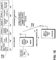
- FIG. 1E is an example illustration of a situation after the next active direct data transfer period or service period has started according to at least one embodiment, showing the transmitting STA 100A has resumed transmitting the buffered data 102 to the receiving STA 100B over the direct data transfer link 110.
- FIG 1E shows an example of the data frame 120AB' as a MAC frame including a header portion and an address and data portion.
- the example header portion includes a field 121 indicating that the frame is a data frame and a field 122 that indicates it is a Tunneled Direct Link Setup (TDLS) packet.
- the example addresses 123" and 124" indicate the STA 100A is the sending station and STA 100B is the destination station.
- the example fields 125' and 128 indicate the next power mode to be the power-on state, and the buffered data 102, respectively.
- Fig. 1E is only an example and other frame formats may be used.
- Fig. 1F is an alternate example embodiment of the initiation of a power save mode operation between the STA 100A and the STA 100B over the common node path 115 through the access point (AP) 50, according to at least one embodiment.
- This example embodiment is applicable to method, apparatus and computer program products.
- the transmitting mobile wireless device STA 100A Prior to the transmitting mobile wireless device STA 100A entering the power save mode, it inserts into a message in the frame 130AD that it transmits to the receiving mobile wireless device STA 100B, a specified time field to indicate when a next active direct data transfer period will start, so that the devices STA 100A and STA 100B can remain in power save mode in the direct data transfer link 110 until that time.
- the value of the time field is set to the next "wakeup time".
- the frame 130AD may be, for example, the last message that is transmitted by the transmitting mobile wireless device STA 100A.
- the message may be, for example, the last message that is transmitted by the transmitting mobile wireless device in the final frame, for instance where the frame has the End Of Service Period (EOSP) bit set to 1 instead of 0.
- EOSP End Of Service Period
- the frame 130AD may be sent through the access point (AP) wireless device 50 and forwarded in frame 130 DB to the receiving mobile wireless device STA 100B.
- the specified time in the message indicates to the receiving device STA 100B when the two devices may start a next active direct data transfer period, service period or session, for example, to transfer data or to complete an operation between two devices over the direct data transfer link 110.
- the signaling between the transmitting STA 100A and the receiving STA 100B over the direct data transfer link 110 enables the transmitting STA 100A and the receiving STA 100B to enter into and return from the power save mode for the direct data transfer communication link 100.
- the embodiments enable two mobile wireless devices (STAs) 100A and 100B to share a common view of the time intervals when they need to be available for the beginning of the service period for direct data transfer. Neither of the mobile wireless devices (STAs) 100A and 100B needs to be available all the time, as is necessary in the legacy 802.11 access point (AP). Instead, the mobile wireless devices (STAs) 100A and 100B may directly signal their availability to each other. After that, the two mobile wireless devices (STAs) 100A and 100B handle the service period and complete it.
- AP legacy 802.11 access point
- the STAs may start data transmission in the service period after:
- data transmission may start after receiving a trigger frame from the receiving station over the common path through the AP 50, in the frequency used in the direct link or other frequency common with the AP, where the AP role may include:
- the example signaling diagram shown in Fig. 3 applies the above description relating to embodiments relating to unidirectional transmission.
- the diagram assumes that STA1 is sending data to STA2 over a direct data transfer link. After transmitting few packets STA1 sends the last packets from its buffer and at the same time sets its power mode (PM) bit to 1 (indicating it is going to the power save mode) and specifies when the receiver can expect the next packet (in Xms). On the reception of this packet, STA2 decides that it can go to into the power save mode, itself, for the Xms time and thus sends an ACK frame to STA1 with the PM bit set to 1.
- PM power mode
- both stations wake up and STA2 transmits a trigger frame to STA1 to check whether there is any frame of data buffered for it. Knowing that STA2 is awake, from having received trigger frame, and knowing that STA2 is ready to receive packets, STA1 starts transmission. When there are no more buffered packets in STA1, the process repeats.
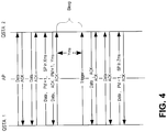
- the example signaling diagram shown in Fig. 4 applies the above description relating to embodiments relating to bidirectional traffic exchange.
- STA1 proposes a next service period (SP) in Xms.
- STA2 due to its traffic pattern, proposes an alternate value of Yms, where Yms ⁇ Xms in this example. Therefore STA1 is the intended receiver for the next packet, and hence applying rule b) it sends a trigger frame to STA2 after Yms.
- both stations may start their traffic exchange.
- the buffers are depleted in both stations, the process repeats.
- STA2 could buffer data for some interval, if delay is not a limiting factor.
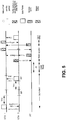
- the example signaling diagram shown in Fig. 5 illustrates light sleep and deep sleep.
- a mobile wireless device STA1 conducting a service in a direct data transfer link enters the power save mode for Xms time, it is in a light sleep state.
- the mobile wireless device STA1 may go into deep sleep state Zs. Deep sleep indicates that the direct link is inactive, but the credentials for the link between the first device STA1 and second device STA2 are still valid and hence could be used with the next service.
- no link set up is required and only activation of the direct data transfer link is needed.
- the activation procedure uses the U-APSD packet delivery mechanism between the two mobile wireless devices STA1 and STA2 in the same infrastructure BSS through the access point (AP). For instance, if the second device STA2 wants to start a new service with the first device STA1, it sends a traffic indication map (TIM) encapsulated in a data frame to the first device STA1.
- the first step is the second device STA2 uses the U-APSD mechanism and sends the encapsulated data to the access point (AP).
- the access point (AP) then performs normal packet delivery to the first device STA1, so the AP indicates in its beacon frame that there is a packet for the first device STA1.
- the first device STA1 transmits a poll frame to the AP to retrieve the encapsulated data containing the traffic indication map (TIM).
- the first device STA1 reads the traffic indication map (TIM) and then sends a trigger frame to the second device STA2 over the direct data transfer link to receive the data packets buffered for it in the second device STA2.
- the second device STA2 transmits the data packets to the first device STA1 over the direct data transfer link.
- Fig. 6 illustrates an external view and a functional block diagram of an example embodiment of the mobile wireless device (STA) 100A.
- the mobile wireless device (STA) 100A may be a mobile communications device, PDA, cell phone, laptop or palmtop computer, or the like.
- the mobile wireless device (STA) 100A includes a control module 620, which includes a central processing unit (CPU) 660, a random access memory (RAM) 662, a read only memory (ROM) 664, and interface circuits 666 to interface with the radio transceiver 608, battery and other power sources, key pad, touch screen, display, microphone, speakers, ear pieces, camera or other imaging devices, etc. in the devices 100A, 100B, and 100C.
- CPU central processing unit
- RAM random access memory
- ROM read only memory
- the RAM 662 and ROM 664 can be removable memory devices such as smart cards, SIMs, WIMs, semiconductor memories such as RAM, ROM, PROMS, flash memory devices, etc.
- the mobile wireless device (STA) 100A includes an Internet protocol stack that includes the user's application program 600 at the top, the Transmission Control Protocol (TCP) transport layer 602, and the Internet Protocol (IP) layer 604, the 802.11 Media Access Control (MAC) layer 606, and the radio transceiver physical layer 608 at the bottom of the protocol stack.
- the 802.11 MAC layer provides functionality to allow reliable data delivery for the upper layers over the wireless medium.
- the 802.11 MAC layer uses the IEEE 802.11 TGz standard, which includes the feature of Direct Link Setup.
- the control module 620, internet protocol stack layers 602, 604, 606, and/or application program 600 can be embodied as program logic stored in the RAM 662 and/or ROM 664 in the form of sequences of programmed instructions which, when executed in the CPU 660, carry out the functions of the disclosed embodiments.
- the program logic can be delivered to the writeable RAM, PROMS, flash memory devices, etc. 662 of the mobile wireless device (STA) 100A from a computer program product or article of manufacture in the form of computer-usable media such as resident memory devices, smart cards or other removable memory devices, or in the form of program logic transmitted over any transmitting medium which transmits such a program.
- the radio 608 in mobile wireless device (STA) 100A can be separate transceiver circuits or alternately, the radio 608 can be a single radio module capable of handling one or multiple channels in a high speed, time and frequency multiplexed manner in response to the control module 620.
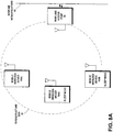
- Fig. 7 is an example network diagram of an infrastructure BSS network 70 according to at least one embodiment, with a mobile wireless device (STA) 100A communicating over a first direct data transfer link 110 with a second mobile wireless device (STA) 100B and communicating over a second direct data transfer link 110' with a third mobile wireless device (STA) 100C, the three mobile wireless devices (STAs) 100A, 100B, and 100C being associated with the access point (AP), which performs wireless-to-wired bridging from the STAs 100A, 100B, and 100C to the wired infrastructure network 60.
- the mobile wireless device (STA) 100A in the infrastructure BSS 70 may coordinate entering into and returning from the power save mode for each direct data transfer link 100 and 100'.
- the transmitting mobile wireless device (STA) 100A can specify to each receiving device (STAs) 100B and 100C substantially the same starting time when the next active direct data transfer period or service period will start, to reduce the number of on/off transitions so as to minimize power consumption.
- the last message frame 120AB that the transmitting STA 100A may transmit in a service period on the direct data transfer link 110, indicating to STA 100B that it intends to begin the power save or sleep mode and the specified time when the next service period will start, which may enable the receiving STA 100B to decide whether it wants to coordinate beginning its power save mode for the same time as the transmitting STA 100A and coordinate remaining in that sleep mode until that specified time occurs, when both STAs 100A and 100B should be awake.
- the message frame 120CA that the transmitting STA 100A may transmit as a last message in a service period according to at least one embodiment on the direct data transfer link 110', indicating to STA 100C that it intends to begin the power save or sleep mode and the specified time when the next service period will start, which may enable the receiving STA 100C to decide whether it wants to coordinate beginning its power save mode for the same time as the transmitting STA 100A and coordinate remaining in that sleep mode until that specified time occurs, when both STAs 100A and 100C should be awake. In this manner STA 100A, STA 100B, and STA 100C may coordinate entering into and returning from the power save mode over the direct data transfer links 110 and 110'.
- the STAs STA 100A, STA 100B, and STA 100C may be in the sleep mode with respect to the direct data transfer links 110 and 110', but most likely the Access point (AP) 50 with which they are associated will not know that they are in the sleep mode.
- AP Access point
- mobile wireless device (STA) 100A in Fig. 7 has data to transmit over a first direct data transfer link 110 to a second mobile wireless device STA 100B and mobile wireless device (STA) 100A receives an indication of a starting time when it will receive data over a second direct data transfer link 110' from a third mobile wireless device STA 100C in the infrastructure BSS 70
- the first mobile wireless device STA 100A may specify substantially the same starting time to the second mobile wireless device STA 100B when the next service period will start over the first direct data transfer link 110, as was received in the indication from the third mobile wireless device STA 100C, in order to reduce the number of on/off transitions so as to minimize power consumption.
- Fig. 8A is an example embodiment network diagram of the infrastructure BSS network of Fig. 1A , showing both the transmitting STA 100A and the receiving STA 100B in the power save mode over the direct data transfer link 110, according to at least one embodiment.
- Fig. 8B shows an example embodiment of the infrastructure BSS network of Fig. 8A , when the next active direct data transfer period is about to start.
- This example embodiment is applicable to method, apparatus and computer program products.
- Fig. 8B shows the receiving STA 100B sending a trigger indication in frame 130BD over the common node path 115 to the access point (AP) 50 for relaying the trigger indication in frame 130DA to the transmitting STA 100A over the common node path 115, according to at least one embodiment.
- the receiving device STA 100B sends the trigger signal based on the indication in the specified time field it received from the transmitting device STA 100A specifying when the next active direct data transfer period will start.
- the trigger signal indicates that the next period is about to start, so that the transmitting device STA 100A can start transmitting data to the receiving device STA 100B via the direct data transfer link 110.
- Fig. 8C shows an example of the infrastructure BSS network of Fig. 8B , after the next active direct data transfer period or service period has started, showing the transmitting STA 100A has resumed transmitting the buffered data in frame 120AB to the receiving STA 100B over the direct data transfer link 110, according to at least one embodiment.
- the resulting embodiments can be implemented with out any changes to the AP.
- the embodiments can be implemented to provide for power saving at STAs that are peer STAs on a direct data transfer link that is operating either in the same band as the AP or in a different band.
- Embodiments include light and deep sleep states, which reduce link establishment process to requiring only one packet exchange through the AP, instead of the previous three packets, which significantly reduces link creation time and energy consumption.
- the embodiments may be implemented as a machine, process, or article of manufacture by using standard programming and/or engineering techniques to produce programming software, firmware, hardware or any combination thereof.
- Any resulting program(s), having computer-readable program code, may be embodied on one or more computer-usable media such as resident memory devices, smart cards or other removable memory devices, or transmitting devices, thereby making a computer program product or article of manufacture according to the embodiments.
- the terms "article of manufacture” and “computer program product” as used herein are intended to encompass a computer program that exists permanently or temporarily on any computer-usable medium or in any transmitting medium which transmits such a program.
- memory/storage devices include, but are not limited to, disks, optical disks, removable memory devices such as smart cards, SIMs, WIMs, semiconductor memories such as RAM, ROM, PROMS, etc.
- Transmitting mediums include, but are not limited to, transmissions via wireless communication networks, the Internet, intranets, telephone/modem-based network communication, hard-wired/cabled communication network, satellite communication, and other stationary or mobile network systems/communication links.
Landscapes
- Engineering & Computer Science (AREA)
- Computer Networks & Wireless Communication (AREA)
- Signal Processing (AREA)
- Mobile Radio Communication Systems (AREA)
Description
- The field of the invention relates to wireless communication and more particularly to power saving in wireless communication devices.
- Modern society has quickly adopted, and become reliant upon, handheld devices for wireless communication. For example, cellular telephones continue to proliferate in the global marketplace due to technological improvements in both the communication quality and device functionality. These wireless communication devices have become common for both personal and business use, allowing users to transmit and receive voice, text and graphical data from a multitude of geographic locations. The communication networks utilized by these devices span different frequencies and cover different transmission distances, each having strengths desirable for various applications.
- Cellular networks facilitate wireless communication over large geographic areas. These network technologies have commonly been divided by generations, starting in the late 1970s to early 1980s with first generation (IG) analog cellular telephones that provided baseline voice communication, to modern digital cellular telephones. Global System for Mobile Communications (GSM) is an example of a widely employed 2G digital cellular network communicating in the 900 MHz/ 1.8 GHz bands in Europe and at 850 MHz and 1.9 GHz in the United States. This network provides voice communication and also supports the transmission of textual data via the Short Messaging Service (SMS). SMS allows a wireless communications device (WCD) to transmit and receive text messages of up to 160 characters, while providing data transfer to packet networks, Integrated Services Digital Network (ISDN) and Plain Old Telephone Service (POTS) users at 9.6 Kbps. The Multimedia Messaging Service (MMS), an enhanced messaging system allowing for the transmission of sound, graphics and video files in addition to simple text, has also become available in certain devices. Soon, emerging technologies such as Digital Video Broadcasting for Handheld Devices (DVB-H) will make streaming digital video, and other similar content, available via direct transmission to a WCD. While long-range communication networks like GSM are a well-accepted means for transmitting and receiving data, due to cost, traffic and legislative concerns, these networks may not be appropriate for all data applications.
- Short-range wireless networks provide communication solutions that avoid some of the problems seen in large cellular networks. Bluetooth™ is an example of a short-range wireless technology quickly gaining acceptance in the marketplace. A 1 Mbps Bluetooth™ radio may transmit and receive data at a rate of 720 Kbps within a range of 10 meters, and may transmit up to 100 meters with additional power boosting. Enhanced Data Rate (EDR) technology, which is also available, may enable maximum asymmetric data rates of 1448 Kbps for a 2 Mbps connection and 2178 Kbps for a 3 Mbps connection. In addition to Bluetooth™, other popular short-range wireless networks include for example IEEE 802.11 Wireless LAN, Wireless Universal Serial Bus (WUSB), Ultra Wideband (UWB), ZigBee (IEEE 802.15.4 and IEEE 802.15.4a), wherein each of these exemplary wireless mediums have features and advantages that make them appropriate for various applications
- The IEEE 802.11 Wireless LAN Standards describe two major components, a mobile wireless device, called a station (STA), and a fixed access point (AP) wireless device. The AP may perform the wireless-to-wired bridging from STAs to a wired network. The basic network is the basic service set (BSS), which is a group of wireless devices that communicate with each other. An infrastructure BSS is a network that has an AP as an essential node.
- The access point (AP) in legacy IEEE 802.11 Wireless LAN networks must relay all communication between the mobile wireless devices (STAs) in an infrastructure BSS. If a STA in an infrastructure BSS wishes to communicate a frame of data to a second STA, the communication must take two hops. First, the originating STA transfers the frame to the AP. Second, the AP transfers the frame to the second STA.
- The access point (AP) in legacy IEEE 802.11 Wireless LAN networks must relay all communication between the mobile wireless devices (STAs) in an infrastructure BSS. If a STA in an infrastructure BSS wishes to communicate a frame of data to a second STA, the communication must take two hops. First, the originating STA transfers the frame to the AP. Second, the AP transfers the frame to the second STA. The access point (AP) in an infrastructure BSS assists those mobile wireless devices (STAs) attempting to save power. The legacy IEEE 802.1 Ie Wireless LAN standards provides for support of low power operation in handheld and battery operated STAs, called automatic power save delivery (APSD). A STA capable of APSD and currently in the power saving mode, will wake up at predetermined beacons received from the AP to listen to a Traffic Indication Map (TIM). If existence of buffered traffic waiting to be sent to the STA is signaled through the TIM, the STA will remain awake until AP sends out all the data. The STA does not need to send a polling signal to the AP to retrieve data, which is the reason for the term "automatic" in the acronym APSD.
- Two variations of the APSD feature are unscheduled automatic power save delivery (U-APSD) and scheduled automatic power save delivery (S-APSD). In U-APSD, the access point (AP) is always awake and hence a mobile wireless device (STA) in the power save mode can send a trigger frame to the AP when the STA wakes up, to retrieve any queued data at the AP and also transmit any data queued from the STA to the AP. In S-APSD, the AP assigns a schedule to a STA and the STA wakes up at the assigned time to retrieve from the AP any data queued for the STA. An AP can maintain multiple schedules either with the same STA or with different STAs in the infrastructure BSS network. Since the AP is never in sleep mode, an AP will maintain different scheduled periods of transmission with different STAs in the infrastructure BSS network to ensure that the STAs get the maximum power savings.
- A next generation IEEE 802.11 WLAN standard is being currently developed as the IEEE 802.11 TGz standard, which includes the feature of Tunneled Direct Link Setup (TDLS) with Channel Switching. This feature enables two mobile wireless devices (STAs) in an infrastructure BSS to directly exchange frames of data over a direct data transfer link, without requiring the access point (AP) in the infrastructure BSS to relay the frames. However, the IEEE 802.11 TGz standard currently under development does not provide means for multiple STAs to enter into a power saving sleep mode, since the AP is no longer available to buffer the frames in the direct data transfer link between the STAs.
-
WO2005/069806 discloses a method of providing power management in a Wireless Local Area Network.US2007/230418 discloses a method for implementing an unscheduled automatic power save delivery in a Wireless Local Area Network.US2005/018624 discloses a power-save QSTA that notifies an access point that it is operating in an automatic power-save delivery mode.EP1033832 discloses a wireless communications system operable in a power saving mode.US2007/0159992 discloses a power saving device and method for a mobile access point. - Method, apparatus, and computer program product embodiments are disclosed to enable power save modes of operation between mobile wireless devices for direct data transfer in an infrastructure BSS.
- A first aspect of the invention is set forth in
claim 1 of the appended claims. A second aspect of the invention is set forth inclaim 3 of the appended claims. A third aspect of the invention is set forth in claim 8 of the appended claims. A fourth aspect of the invention is set forth in claim 13 of the appended claims. - An example embodiment enables a power save mode operation between the mobile wireless devices for direct data transfer. Prior to a transmitting mobile wireless device entering the power save mode, it inserts into a message it transmits to a receiving mobile wireless device, a specified time field to indicate when a next active direct data transfer period will start, so that the devices can remain in power save mode in a direct data transfer link until that time. The value of the time field is set to the next "wakeup time". The message may be, for example, the last message that is transmitted by the transmitting mobile wireless device in the final frame, for instance where the frame has the End Of Service Period (EOSP) bit set to 1 instead of 0. The message may be sent over the direct data transfer link to the receiving mobile wireless device or alternately, it may be sent through an access point wireless device or any other wireless device to the receiving mobile wireless device. The specified time in the message indicates to the receiving device when the two devices may start a next active direct data transfer period, service period or session, for example, to transfer data or to complete an operation between two devices over the direct data transfer link. The message may enable both the transmitting and receiving devices to begin a power save mode in the direct data transfer link and to remain in the power save mode until the specified time, when the transmitting device may start transmitting data to the receiving device via the direct data transfer link.
- Then, when the next active direct data transfer period is about to start, the receiving device sends a trigger signal based on the specified time indication, the trigger signal indicating that the next period is about to start, so that the transmitting device can start transmitting data to the receiving device via the direct data transfer link. The trigger signal may be sent over the direct data transfer link to the transmitting mobile wireless device or alternately, it may be sent through an access point wireless device or any other wireless device to the transmitting mobile wireless device.
- The signaling between the mobile wireless devices enables the devices to enter into and return from the power save mode for a direct data transfer communication link. The embodiment enables two mobile wireless devices to share a common view of the time intervals when they need to be available for the beginning of the next active direct data transfer period, service period or session for direct data transfer. Neither of the mobile wireless devices needs to be available all the time, as is necessary in the legacy 802.11 access point (AP). Instead, the mobile wireless devices can directly signal their availability to each other. After that, the two mobile wireless devices handle the next active direct data transfer period, service period or session and complete it.
- An example embodiment enables a mobile wireless device in an infrastructure BSS to manage two or more direct data transfer links with two or more other mobile wireless devices in that BSS and coordinate entering into and returning from the power save mode for each direct data transfer link. If one of the mobile wireless devices has data to transmit to each of the other mobile wireless devices, the transmitting device can specify to each receiving device substantially the same starting time when the next active direct data transfer period, service period or session will start, to reduce the number of on/off transitions so as to minimize power consumption. If a first mobile wireless devices has data to transmit over a first direct data transfer link to a second mobile wireless device and receives an indication of a starting time when it will receive data over a second direct data transfer link from a third mobile wireless device in the infrastructure BSS, the first mobile wireless device can specify substantially the same starting time to the second mobile wireless device when the next active direct data transfer period, service period or session will start over the first direct data transfer link, to reduce the number of on/off transitions so as to minimize power consumption.
- In an example embodiment, when a mobile wireless device (STA) conducting a service in a direct data transfer link, enters the power save mode, it is in a light sleep state. The service may be, for example, a session required to transfer data or to complete an operation between two devices over the direct data transfer link. When the service ends, the mobile wireless device can go into deep sleep state. Deep sleep indicates that the direct link is inactive, but the credentials for the link between the first and second devices are still valid and hence could be used with the next service. Thus, for the next service between the first and second devices (STAs), no link set up is required and only activation of the direct data transfer link is needed. The activation procedure uses the U-APSD packet delivery mechanism between the two mobile wireless devices in the same infrastructure BSS through the access point (AP). For instance, if the second device wants to start a new service with the first device, it sends a traffic indication map (TIM) encapsulated in a data frame to the first device. The first step is the second device uses the U-APSD mechanism and sends the encapsulated data to the access point (AP). The access point (AP) then performs normal packet delivery to the first device, so the AP indicates in the beacon frame that there is a packet for the first device. Consequently, the first device transmits a poll frame to the AP to retrieve the encapsulated data and after that it sends a trigger frame to the second device over the direct data transfer link to receive the data packets buffered for it in the second device. The second device transmits the data packets to the first device over the direct data transfer link.
- In an example embodiment, the transmitting mobile wireless device may transmit the message initiating the power save modes to the receiving mobile wireless device over a common node path through the access point (AP) or any other wireless station, according to at least one embodiment.
- In an example embodiment, when the next active direct data transfer period, service period or session is about to start, the receiving STA may send a trigger indication over the common node path to the access point (AP) or any other wireless station, for relaying the trigger indication to the transmitting STA over the common node path to the receiving STA.
-
-
Fig. 1A is an example network diagram of an infrastructure BSS network, with three mobile wireless devices (STAs) and an access point (AP), which performs wireless-to-wired bridging from the STAs to a wired infrastructure network. -
Fig. 1B is an example of the initiation of a power save mode operation between the STAs over the direct data transfer link. -
Fig. 1C is an example embodiment network diagram of the infrastructure BSS network ofFig. 1A , showing both the transmitting STA and the receiving STA in the power save mode over the direct data transfer link. -
Fig. 1D is an example when the next active direct data transfer period, service period or session is about to start, showing the receiving STA sending a trigger indication to the transmitting STA over the direct data transfer link according to at least one embodiment. -
Fig. 1E is an example after the next active direct data transfer period, service period or session has started, showing the transmitting STA has resumed transmitting the buffered data to the receiving STA over the direct data transfer link according to at least one embodiment. -
Fig. 1F is an alternate example of the initiation of a power save mode operation between the STAs over the common node path through the access point (AP), according to at least one embodiment. -
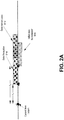
Fig. 2A illustrates a first example of conditions used to determine the start time of the next transmission by the transmitting STA according to at least one embodiment. -
Fig. 2B illustrates a second example of conditions used to determine the start time of the next transmission by the transmitting STA according to at least one embodiment. -
Fig. 3 is an example signaling diagram unidirectional data transmission according to at least one embodiment. -
Fig. 4 is an example signaling diagram bidirectional transmission according to at least one embodiment. -
Fig. 5 illustrates an example of light sleep, deep sleep and link activation according to at least one embodiment. -
Fig. 6 illustrates an external view and a functional block diagram of an example embodiment of the mobile wireless device (STA). -
Fig. 7 is an example network diagram of aninfrastructure BSS network 70 according to at least one embodiment, with a mobile wireless device (STA) 100A communicating over a first direct data transfer link 110 with a second mobile wireless device (STA) 100B and communicating over a second direct data transfer link 110' with a third mobile wireless device (STA) 100C, the three mobile wireless devices (STAs) 100A, 100B, and 100C being associated with the access point (AP), which performs wireless-to-wired bridging from theSTAs wired infrastructure network 60. -
Fig. 8A is an example embodiment network diagram of the infrastructure BSS network ofFig. 1A , showing both the transmittingSTA 100A and the receivingSTA 100B in the power save mode over the directdata transfer link 110, according to at least one embodiment. -
Fig. 8B shows an example of the infrastructure BSS network ofFig. 8A , when the next active direct data transfer period, service period or session is about to start, showing the receivingSTA 100B sending a trigger indication in frame 130BD over thecommon node path 115 to the access point (AP) 50 for relaying the trigger indication in frame 130DA to the transmittingSTA 100A over thecommon node path 115, according to at least one embodiment. -
Fig. 8C shows an example of the infrastructure BSS network ofFig. 8B , after the next active direct data transfer period, service period or session has started, showing the transmittingSTA 100A has resumed transmitting the buffered data in frame 120AB to the receivingSTA 100B over the directdata transfer link 110, according to at least one embodiment. -
Fig. 1A is an example embodiment network diagram of an exemplaryinfrastructure BSS network 70, with three mobile wireless devices (STAs) 100A, 100B, and 100C and an access point (AP) 50, which performs wireless-to-wired bridging from theSTAs wired infrastructure network 60. TheSTAs STAs infrastructure BSS 70 to directly exchange frames of data over a direct data transfer link, without requiring the access point (AP) 50 in the infrastructure BSS to relay the frames. For example,Fig. 1A shows theSTAs Fig. 1A shows theSTA 100C and theAP 50 exchanging frames of data 130DC and 130CD in accordance with the IEEE 802.11e WLAN standard. In addition to the access point (AP) 50 performing the wireless-to-wired bridging from the mobile wireless devices (STAs) 100A and 100B to thewired infrastructure network 60, the access point (AP) 50 can also relay communications between the mobile wireless devices (STAs) 100A, 100B, and 100C in theinfrastructure BSS 70. -
Fig. 1B illustrates an example embodiment of the initiation of a power save mode of operation between theSTAs wireless device STA 100A entering the power save mode, it inserts into a message in frame 120AB that it transmits to the receiving mobilewireless device STA 100B, a specifiedtime field 126 to indicate when a next active direct data transfer period will start, so that thedevices STA 100A andSTA 100B can remain in power save mode in the directdata transfer link 110 until that time. The value of thetime field 126 is set to the next "wakeup time". The message may be, for example, the last message that is transmitted by the transmitting mobile wireless device in the final frame, for instance where the frame has the End Of Service Period (EOSP) bit set to 1 instead of 0. -
FIG 1B shows the message frame 120AB that the transmittingSTA 100A may transmit, for example, in a last message frame of an active direct data transfer period, service period or session on the directdata transfer link 110, indicating infield 125 that it intends to begin the power save or sleep mode. The active direct data transfer period, service period or session may be, for example, the duration of a session required to transfer data or to complete an operation between two devices over the direct data transfer link. The example embodiment ofFIG 1B shows the transmittingSTA 100A is expecting to havedata 102 to be transmitted to the receivingSTA 100B.FIG 1B shows the transmittingSTA 100A inserting in the last message frame 120AB according to an embodiment, aspecified time 126 when the next active direct data transfer period, service period or session will start and the expecteddata rate 127, which will enable the receivingSTA 100B to decide whether it wants to coordinate beginning of its power save mode for the same time as the transmittingSTA 100A and coordinate remaining in the power save mode until that specifiedtime 126 occurs, when bothSTAs manner STA 100A andSTA 100B may coordinate entering into and returning from the power save mode over the direct data transfer link. TheSTAs data transfer link 110, but most likely the Access point (AP) 50 with which they are associated will not know that they are in the sleep mode with respect to the directdata transfer link 110, as the STA's 100A and 100B may remain active in respect to heinfrastructure BSS network 70 while being the sleep mode with respect to the directdata transfer link 110.FIG 1B shows an example of the last message frame 120AB as a MAC frame including a header portion and an address and data portion. The example header portion may include afield 121 indicating that the frame is a data frame and afield 122 that indicates it is a Tunneled Direct Link Setup (TDLS) packet. The example addresses 123 and 124 indicate the transmittingSTA 100A and receivingSTA 100B. The example fields 125, 126, and 127 indicate the next power mode, the specified time when the next active direct data transfer period, service period or session will start, and the expected data rate, respectively. It should be noted that theFig. 1B is only an example and other frame formats may be used without departing the scope of the present invention. Further, it should be noted that the present application is not intended to be limited only to embodiments where the last message frame includes the indications relating to power save mode of directdata transfer link 110. - In the specification of the next transmission time to indicate when the next active direct data transfer period will start, the value in the
time field 126 may be signaled in units of the Time Unit (TU), which is used to indicate a unit of time equal to 1024 microseconds. The value in thetime field 126 is specified relative to the Timing Synchronization Function (TSF) transmitted in the last beacon from the access point (AP) 50. In an Independent Basic Service Set (IBSS) or an Ad-hoc network, thetime field 126 is specified relative to the TSF in the last beacon. In the case of multi-band operation, where theSTAs data transfer link 110, then the TSF of the access point (AP) 50 in the common band they share with the AP, is used. - In another example embodiment, the transmitting
STA 100A and the receivingSTA 100B may agree in a handshaking protocol over: - a) the direct
data transfer link 110, or - b) the
common path 115 through the AP, on the common "wakeup time". The transmittingSTA 100A may suggest a schedule to the receivingSTA 100B and the receivingSTA 100B may respond with an alternate suggestion, until both stations negotiate an agreement on a common "wakeup time". - In another embodiment, the transmitting
STA 100A and the receivingSTA 100B, after agreeing on a common wakeup time interval, may only send updates to that time if it is going to be changed. No signaling is required if wakeup time is not changing from established time. Hence, support for periodic power save schedule can be provided. A handshake protocol conducted by the transmittingSTA 100A and the receivingSTA 100B over either thecommon node path 115 through the AP or direct path when creating or activating the directdata transfer link 110 may negotiate the starting instant of the first "wakeup time", the duration of the power save and awake intervals. Thecommon node path 115 is a data transfer path that includes theaccess point 50 or any other wireless station. - In yet another example embodiment, the start time of the next active direct data transfer period, service period or session may be calculated by the transmitting
STA 100A in the following manner: - 1. A traffic specification (TSPEC) information element may be sent by the transmitting
STA 100A to the receivingSTA 100B in a management frame, which may indicate the expected data rate and the service period of the data transfer. - 2. The transmitting
STA 100A may be the one in control to make a decision regarding the time when the receivingSTA 100B needs to be awake to receive the data from the transmittingSTA 100A. Therefore, in the last data frame transmitted 120AB, the transmittingSTA 100A signals the receivingSTA 100B the start time for the next data transmission. - Some of the constraints based on which transmitting
STA 100A picks the start time may include : - (a) Number of STAs to which the transmitting
STA 100A is transmitting data and their traffic pattern. In the scenario where there are one or more STAs in theinfrastructure BSS 70, which are scheduled to receive data from the transmittingSTA 100A and the traffic patterns are such that:- # there is an overlap in the service periods
- # have the same service period
- # the service period for the STAs are multiples of each other ... etc,
STAs STA 100A would need to be awake to transmit the data. - (b) If the transmitting
STA 100A is also a receiver (to receive data from anotherSTA 100C and not the receivingSTA 100B) and the transmittingSTA 100A is already scheduled to be awake at a certain period of time, then the transmittingSTA 100A may schedule the receivingSTA 100B, which is to receive data from the transmittingSTA 100A, to be awake at a time close to transmittingSTA 100A's awake time and still meet the Quality of Service (QoS) requirement. - For instance, let t1 be the minimum time of next data reception by the transmitting
STA 100A (referred to here as the transmitter T) and t2 be the time of the start of the next service period (but not yet signaled), then the following conditions may be used to determine the start time of the next transmission by the transmittingSTA 100A according to at least one embodiment: - • If (t1 <= t2) then set t2 = Max (t2, t1 + data reception time by
STA 100A), (seeFig. 2A ). - • If (t1 > t2) then
- • If ((t2 + data transmit time) > t1 + data reception time by
STA 100A) then - • t2 = t1 + data reception time by
STA 100A (seeFig. 2B ). - This condition insures that the transmitting
STA 100A is not busy transmitting data to its receivers, until the expiration of its data reception time (t1 + data reception time bySTA 100A). - In yet another embodiment, the transmitting
STA 100A having multiple direct links with receiver stations, may overlap corresponding service periods towards different receivers in order to provide: - a) multicast data delivery to the receivers, or
- b) controlled data delivery towards the transmitter station from receiver stations, for example, by using a Power Save Multi Poll (PSMP) mechanism.
- In embodiments, the power save states of the transmitting
STA 100A and the receivingSTA 100B in the directdata transfer link 110 are readily aligned with the power save states required by the access point (AP) 50, since the directdata transfer link 110 is operated in the same frequency channel as theinfrastructure BSS 70. In other embodiments where the directdata transfer link 110 may be operated in a different frequency channel from that of theinfrastructure BSS 70, alignment of the power save states for the directdata transfer link 110 might be performed only when bothSTA 100A andSTA 100B are in power save mode for the AP. -
Fig. 1C is an example embodiment network diagram of theinfrastructure BSS network 70 ofFig. 1A , showing both the transmittingSTA 100A and the receivingSTA 100B in the power save mode over the directdata transfer link 110. TheSTAs data transfer link 110, but most likely the Access point (AP) 50 with which they are associated will not know that they are in the sleep mode with respect to the directdata transfer link 110. -
Fig. 1D is an example illustration of a situation when the next active direct data transfer period is about to start according to at least one embodiment. When the next active direct data transfer period is about to start, the receivingdevice STA 100B sends atrigger signal 128 in frame 120BA based on the indication in the specifiedtime field 126 it received in frame 120AB from the transmittingdevice STA 100A specifying when the next active direct data transfer period will start. Thetrigger signal 128 in frame 120BA indicates that the next period is about to start, so that the transmittingdevice STA 100A can start transmitting data to thereceiving device STA 100B via the directdata transfer link 110. The trigger signal in frame 120BA may be sent over the direct data transfer link 110 to the transmitting mobilewireless device STA 100A. Alternately, as shown inFig. 8B , trigger signal may be sent in trigger frames 130BD and 130DA through the access point (AP)wireless device 50, or through any other wireless device, to the transmitting mobilewireless device STA 100A. -
Fig. 1D shows the receivingSTA 100B sending thetrigger indication 128 in the frame 120BA to the transmittingSTA 100A over the directdata transfer link 110, confirming to the transmittingSTA 100A that the receivingSTA 100B has awakened, so that the transmittingSTA 100A may resume transmitting the buffereddata 102 to the receivingSTA 100B over the directdata transfer link 110. In thismanner STA 100A andSTA 100B may coordinate returning from the power save mode over the direct data transfer link.FIG 1D shows an example of the trigger frame 120BA as a MAC frame including a header portion and an address and data portion. The example header portion includes afield 121 indicating that the frame is a data frame and afield 122 that indicates it is a Tunneled Direct Link Setup (TDLS) packet. The example addresses 123' and 124' indicate theSTA 100B is the sending station andSTA 100A is the destination station. The example fields 125', and 128 indicate the next power mode to be the power-on state, and the trigger indication, respectively. It should be noted that theFig. 1D is only an example and other frame formats may be used without departing the scope of the present application. - In another example embodiment, there can be a timeout interval specified for the transmitting
STA 100A waiting for a trigger frame 120BA from the receivingSTA 100B. For example, such a timeout interval may be a function of the next target beacon transmission time (TBTT) and/or End_time (where End_time is a time after which transmittingstation STA 100A is no longer available for receivingstation STA 100B). The timeout interval could be estimated as
min(TBTT, End_time). - In case there was no indication that stations are awake during a timeout interval, they may switch to another band common to both stations or switch the transmission over the
common node path 115 that includes theaccess point 50 or any other wireless station. -
Fig. 1E is an example illustration of a situation after the next active direct data transfer period or service period has started according to at least one embodiment, showing the transmittingSTA 100A has resumed transmitting the buffereddata 102 to the receivingSTA 100B over the directdata transfer link 110.FIG 1E shows an example of the data frame 120AB' as a MAC frame including a header portion and an address and data portion. The example header portion includes afield 121 indicating that the frame is a data frame and afield 122 that indicates it is a Tunneled Direct Link Setup (TDLS) packet. The example addresses 123" and 124" indicate theSTA 100A is the sending station andSTA 100B is the destination station. The example fields 125' and 128 indicate the next power mode to be the power-on state, and the buffereddata 102, respectively.Fig. 1E is only an example and other frame formats may be used. -
Fig. 1F is an alternate example embodiment of the initiation of a power save mode operation between theSTA 100A and theSTA 100B over thecommon node path 115 through the access point (AP) 50, according to at least one embodiment. This example embodiment is applicable to method, apparatus and computer program products. Prior to the transmitting mobilewireless device STA 100A entering the power save mode, it inserts into a message in the frame 130AD that it transmits to the receiving mobilewireless device STA 100B, a specified time field to indicate when a next active direct data transfer period will start, so that thedevices STA 100A andSTA 100B can remain in power save mode in the directdata transfer link 110 until that time. The value of the time field is set to the next "wakeup time". The frame 130AD may be, for example, the last message that is transmitted by the transmitting mobilewireless device STA 100A. The message may be, for example, the last message that is transmitted by the transmitting mobile wireless device in the final frame, for instance where the frame has the End Of Service Period (EOSP) bit set to 1 instead of 0. The frame 130AD may be sent through the access point (AP)wireless device 50 and forwarded in frame 130 DB to the receiving mobilewireless device STA 100B. The specified time in the message indicates to thereceiving device STA 100B when the two devices may start a next active direct data transfer period, service period or session, for example, to transfer data or to complete an operation between two devices over the directdata transfer link 110. - In embodiments, the signaling between the transmitting
STA 100A and the receivingSTA 100B over the directdata transfer link 110 enables the transmittingSTA 100A and the receivingSTA 100B to enter into and return from the power save mode for the direct data transfer communication link 100. The embodiments enable two mobile wireless devices (STAs) 100A and 100B to share a common view of the time intervals when they need to be available for the beginning of the service period for direct data transfer. Neither of the mobile wireless devices (STAs) 100A and 100B needs to be available all the time, as is necessary in the legacy 802.11 access point (AP). Instead, the mobile wireless devices (STAs) 100A and 100B may directly signal their availability to each other. After that, the two mobile wireless devices (STAs) 100A and 100B handle the service period and complete it. - In embodiments where there is bi-directional data transfer between the transmitting
STA 100A and the receivingSTA 100B over the directdata transfer link 110, the STAs may start data transmission in the service period after: - a) STAs at both end points send a trigger frame 120BA (reception of a trigger frame at any end point implies that recipient station deletes its pending trigger frame to the originator of the received trigger frame), or
- b) STA being the next intended receiver sends a trigger frame, or
- c) transmitting STA is aware that the receiver STA is awake during scheduled service period, implicit transmission.
- In another embodiment, data transmission may start after receiving a trigger frame from the receiving station over the common path through the
AP 50, in the frequency used in the direct link or other frequency common with the AP, where the AP role may include: - a) forwarding the packet to the transmitting station, or
- b) enhanced packet forwarding where the AP is aware of existing direct communication (e.g. use of the highest priority for forwarded packet or placing forwarded packet to the head of the queue)
- The example signaling diagram shown in
Fig. 3 applies the above description relating to embodiments relating to unidirectional transmission. The diagram assumes that STA1 is sending data to STA2 over a direct data transfer link. After transmitting few packets STA1 sends the last packets from its buffer and at the same time sets its power mode (PM) bit to 1 (indicating it is going to the power save mode) and specifies when the receiver can expect the next packet (in Xms). On the reception of this packet, STA2 decides that it can go to into the power save mode, itself, for the Xms time and thus sends an ACK frame to STA1 with the PM bit set to 1. After the time Xms occurs, both stations wake up and STA2 transmits a trigger frame to STA1 to check whether there is any frame of data buffered for it. Knowing that STA2 is awake, from having received trigger frame, and knowing that STA2 is ready to receive packets, STA1 starts transmission. When there are no more buffered packets in STA1, the process repeats. - The example signaling diagram shown in
Fig. 4 applies the above description relating to embodiments relating to bidirectional traffic exchange. When both stations empty their buffers, they may negotiate when the next active direct data transfer period or service period should start, based on the above description. InFig. 4 , it is shown that STA1 proposes a next service period (SP) in Xms. However, STA2, due to its traffic pattern, proposes an alternate value of Yms, where Yms < Xms in this example. Therefore STA1 is the intended receiver for the next packet, and hence applying rule b) it sends a trigger frame to STA2 after Yms. When STA2 receives the trigger frame, both stations may start their traffic exchange. When the buffers are depleted in both stations, the process repeats. In embodiments, STA2 could buffer data for some interval, if delay is not a limiting factor. - The example signaling diagram shown in
Fig. 5 illustrates light sleep and deep sleep. In an example embodiment, when a mobile wireless device STA1 conducting a service in a direct data transfer link, enters the power save mode for Xms time, it is in a light sleep state. When the service ends, the mobile wireless device STA1 may go into deep sleep state Zs. Deep sleep indicates that the direct link is inactive, but the credentials for the link between the first device STA1 and second device STA2 are still valid and hence could be used with the next service. Thus, for the next service between the first and second devices STA1 and STA2, no link set up is required and only activation of the direct data transfer link is needed. The activation procedure uses the U-APSD packet delivery mechanism between the two mobile wireless devices STA1 and STA2 in the same infrastructure BSS through the access point (AP). For instance, if the second device STA2 wants to start a new service with the first device STA1, it sends a traffic indication map (TIM) encapsulated in a data frame to the first device STA1. The first step is the second device STA2 uses the U-APSD mechanism and sends the encapsulated data to the access point (AP). The access point (AP) then performs normal packet delivery to the first device STA1, so the AP indicates in its beacon frame that there is a packet for the first device STA1. Consequently, the first device STA1 transmits a poll frame to the AP to retrieve the encapsulated data containing the traffic indication map (TIM). The first device STA1 reads the traffic indication map (TIM) and then sends a trigger frame to the second device STA2 over the direct data transfer link to receive the data packets buffered for it in the second device STA2. The second device STA2 transmits the data packets to the first device STA1 over the direct data transfer link. -
Fig. 6 illustrates an external view and a functional block diagram of an example embodiment of the mobile wireless device (STA) 100A. The mobile wireless device (STA) 100A may be a mobile communications device, PDA, cell phone, laptop or palmtop computer, or the like. The mobile wireless device (STA) 100A includes acontrol module 620, which includes a central processing unit (CPU) 660, a random access memory (RAM) 662, a read only memory (ROM) 664, andinterface circuits 666 to interface with theradio transceiver 608, battery and other power sources, key pad, touch screen, display, microphone, speakers, ear pieces, camera or other imaging devices, etc. in thedevices RAM 662 andROM 664 can be removable memory devices such as smart cards, SIMs, WIMs, semiconductor memories such as RAM, ROM, PROMS, flash memory devices, etc. The mobile wireless device (STA) 100A includes an Internet protocol stack that includes the user'sapplication program 600 at the top, the Transmission Control Protocol (TCP)transport layer 602, and the Internet Protocol (IP)layer 604, the 802.11 Media Access Control (MAC)layer 606, and the radio transceiverphysical layer 608 at the bottom of the protocol stack. The 802.11 MAC layer provides functionality to allow reliable data delivery for the upper layers over the wireless medium. The 802.11 MAC layer uses the IEEE 802.11 TGz standard, which includes the feature of Direct Link Setup. - The
control module 620, internet protocol stack layers 602, 604, 606, and/orapplication program 600 can be embodied as program logic stored in theRAM 662 and/orROM 664 in the form of sequences of programmed instructions which, when executed in theCPU 660, carry out the functions of the disclosed embodiments. The program logic can be delivered to the writeable RAM, PROMS, flash memory devices, etc. 662 of the mobile wireless device (STA) 100A from a computer program product or article of manufacture in the form of computer-usable media such as resident memory devices, smart cards or other removable memory devices, or in the form of program logic transmitted over any transmitting medium which transmits such a program. Alternately, they can be embodied as integrated circuit logic in the form of programmed logic arrays or custom designed application specific integrated circuits (ASIC). Theradio 608 in mobile wireless device (STA) 100A can be separate transceiver circuits or alternately, theradio 608 can be a single radio module capable of handling one or multiple channels in a high speed, time and frequency multiplexed manner in response to thecontrol module 620. -
Fig. 7 is an example network diagram of aninfrastructure BSS network 70 according to at least one embodiment, with a mobile wireless device (STA) 100A communicating over a first direct data transfer link 110 with a second mobile wireless device (STA) 100B and communicating over a second direct data transfer link 110' with a third mobile wireless device (STA) 100C, the three mobile wireless devices (STAs) 100A, 100B, and 100C being associated with the access point (AP), which performs wireless-to-wired bridging from theSTAs wired infrastructure network 60. The mobile wireless device (STA) 100A in theinfrastructure BSS 70 may coordinate entering into and returning from the power save mode for each direct data transfer link 100 and 100'. - If mobile wireless device (STA) 100A in
Fig. 7 has data to transmit to each of the other mobile wireless devices (STAs) 100B and 100C, the transmitting mobile wireless device (STA) 100A can specify to each receiving device (STAs) 100B and 100C substantially the same starting time when the next active direct data transfer period or service period will start, to reduce the number of on/off transitions so as to minimize power consumption. The last message frame 120AB that the transmittingSTA 100A may transmit in a service period on the directdata transfer link 110, indicating toSTA 100B that it intends to begin the power save or sleep mode and the specified time when the next service period will start, which may enable the receivingSTA 100B to decide whether it wants to coordinate beginning its power save mode for the same time as the transmittingSTA 100A and coordinate remaining in that sleep mode until that specified time occurs, when bothSTAs STA 100A may transmit as a last message in a service period according to at least one embodiment on the direct data transfer link 110', indicating toSTA 100C that it intends to begin the power save or sleep mode and the specified time when the next service period will start, which may enable the receivingSTA 100C to decide whether it wants to coordinate beginning its power save mode for the same time as the transmittingSTA 100A and coordinate remaining in that sleep mode until that specified time occurs, when bothSTAs manner STA 100A,STA 100B, andSTA 100C may coordinate entering into and returning from the power save mode over the directdata transfer links 110 and 110'. TheSTAs STA 100A,STA 100B, andSTA 100C may be in the sleep mode with respect to the directdata transfer links 110 and 110', but most likely the Access point (AP) 50 with which they are associated will not know that they are in the sleep mode. - If mobile wireless device (STA) 100A in
Fig. 7 has data to transmit over a first direct data transfer link 110 to a second mobilewireless device STA 100B and mobile wireless device (STA) 100A receives an indication of a starting time when it will receive data over a second direct data transfer link 110' from a third mobilewireless device STA 100C in theinfrastructure BSS 70, the first mobilewireless device STA 100A may specify substantially the same starting time to the second mobilewireless device STA 100B when the next service period will start over the first directdata transfer link 110, as was received in the indication from the third mobilewireless device STA 100C, in order to reduce the number of on/off transitions so as to minimize power consumption. -
Fig. 8A is an example embodiment network diagram of the infrastructure BSS network ofFig. 1A , showing both the transmittingSTA 100A and the receivingSTA 100B in the power save mode over the directdata transfer link 110, according to at least one embodiment. -
Fig. 8B shows an example embodiment of the infrastructure BSS network ofFig. 8A , when the next active direct data transfer period is about to start. This example embodiment is applicable to method, apparatus and computer program products.Fig. 8B shows the receivingSTA 100B sending a trigger indication in frame 130BD over thecommon node path 115 to the access point (AP) 50 for relaying the trigger indication in frame 130DA to the transmittingSTA 100A over thecommon node path 115, according to at least one embodiment. When the next active direct data transfer period is about to start, the receivingdevice STA 100B sends the trigger signal based on the indication in the specified time field it received from the transmittingdevice STA 100A specifying when the next active direct data transfer period will start. The trigger signal indicates that the next period is about to start, so that the transmittingdevice STA 100A can start transmitting data to thereceiving device STA 100B via the directdata transfer link 110. -
Fig. 8C shows an example of the infrastructure BSS network ofFig. 8B , after the next active direct data transfer period or service period has started, showing the transmittingSTA 100A has resumed transmitting the buffered data in frame 120AB to the receivingSTA 100B over the directdata transfer link 110, according to at least one embodiment. - The resulting embodiments can be implemented with out any changes to the AP. The embodiments can be implemented to provide for power saving at STAs that are peer STAs on a direct data transfer link that is operating either in the same band as the AP or in a different band. Embodiments include light and deep sleep states, which reduce link establishment process to requiring only one packet exchange through the AP, instead of the previous three packets, which significantly reduces link creation time and energy consumption.
- Using the description provided herein, the embodiments may be implemented as a machine, process, or article of manufacture by using standard programming and/or engineering techniques to produce programming software, firmware, hardware or any combination thereof.
- Any resulting program(s), having computer-readable program code, may be embodied on one or more computer-usable media such as resident memory devices, smart cards or other removable memory devices, or transmitting devices, thereby making a computer program product or article of manufacture according to the embodiments. As such, the terms "article of manufacture" and "computer program product" as used herein are intended to encompass a computer program that exists permanently or temporarily on any computer-usable medium or in any transmitting medium which transmits such a program.
- As indicated above, memory/storage devices include, but are not limited to, disks, optical disks, removable memory devices such as smart cards, SIMs, WIMs, semiconductor memories such as RAM, ROM, PROMS, etc. Transmitting mediums include, but are not limited to, transmissions via wireless communication networks, the Internet, intranets, telephone/modem-based network communication, hard-wired/cabled communication network, satellite communication, and other stationary or mobile network systems/communication links.
- The features described herein may be employed in networks other than Wireless LAN networks.
Claims (15)
- A method comprising:a transmitting peer mobile wireless device (100A) transmitting an indication (120AB) to a receiving peer mobile wireless device (100B) when a next active direct data transfer period (126) between the devices will start so that the devices can remain in power save mode in a direct data transfer link (110) until that time; andreceiving from the receiving peer mobile wireless device (100B), a trigger signal (120BA) based on said indication, the trigger signal indicating that the next period is about to start (125'), so that the transmitting peer mobile wireless device can start transmitting data (120AB') to the receiving peer mobile wireless device via the direct data transfer link (110).
- The method of claim 1, which further comprises:sending a traffic indication map encapsulated in a data frame from the transmitting peer mobile wireless device to an access point, for indicating that there is a data packet buffered in the transmitting peer mobile wireless device for the receiving peer mobile wireless device; andtransmitting the data packet over the direct data transfer link to the receiving peer mobile wireless device after the access point has notified the receiving peer mobile wireless device that the transmitting peer mobile wireless device device has a data packet buffered for it.
- A method for a receiving peer mobile wireless device (100B), comprising:receiving in a peer mobile wireless device (100B) an indication (120AB) from a transmitting peer mobile wireless device (100A) when a next active direct data transfer period (126) between the devices will start so that the devices can remain in power save mode in a direct data transfer link (110) until that time; andsending to the transmitting peer mobile wireless device (100A), a trigger signal (120BA) based on said indication, the trigger signal indicating that the next period is about to start (125'), so that the transmitting peer mobile wireless device can start transmitting data (120AB') via the direct data transfer link (110).
- The method of any preceding claim, comprising the transmitting peer mobile wireless device negotiating with the receiving peer mobile wireless device a common view of time intervals when the devices need to be available for the beginning of the next active direct data direct data transfer period.
- The method of claim 3 or claim 4, which further comprises:receiving in the receiving peer mobile wireless device a traffic indication map encapsulated in a data frame from an access point, for indicating that there is a data packet buffered in the transmitting peer mobile wireless device for the receiving peer mobile wireless device; andreceiving in the receiving peer mobile wireless device, the data packet over the direct data transfer link from the transmitting peer mobile wireless device.
- A computer program comprising computer readable program code configured to cause performing of the method according to any of claims 1 to 5 when said program is run on a computer.
- The computer program according to claim 6, wherein the computer program is a computer program product comprising a computer-readable medium bearing computer program code embodied therein for use with a computer.
- A transmitting peer mobile wireless device (100A), comprising:means (608) for transmitting an indication (120AB) to a receiving peer mobile wireless device (100B) when a next active direct data transfer period (126) between the devices will start so that the devices can remain in power save mode in a direct data transfer link (110) until that time; andmeans (608) for receiving from the receiving peer mobile wireless (100B), a trigger signal (120BA) based on said indication, the trigger signal indicating that the next period is about to start (125'), so that the transmitting peer mobile wireless device can start transmitting data (120AB') to the receiving peer mobile wireless device via the direct data transfer link (110).
- The transmitting peer mobile wireless device of claim 8, configured to negotiate with the receiving peer mobile wireless device a common view of time intervals when the devices need to be available for the beginning of next active direct data direct data transfer period.
- The transmitting peer mobile wireless device of claim 8 or claim 9, which further comprises:means (608) for sending a traffic indication map encapsulated in a data frame from the transmitting peer mobile wireless device to an access point, for indicating that there is a data packet buffered in the transmitting peer mobile wireless device for the receiving peer mobile wireless device; andmeans (608) for transmitting the data packet over the direct data transfer link to the receiving peer mobile wireless device after the access point has notified the receiving peer mobile wireless device that the transmitting peer mobile wireless device has a data packet buffered for it.
- The transmitting peer mobile wireless device of any of claims 8 to 10, wherein said indication of when a next period will start is included in a last message transmitted by the transmitting peer mobile wireless device in a period in the direct data transfer link.
- The transmitting peer mobile wireless device of any of claims 8 to 11, wherein the trigger signal is sent from the receiving peer mobile wireless device over the direct data transfer link to the transmitting peer mobile wireless device.
- A receiving peer mobile wireless device (100B), comprising:means (608) for receiving an indication (120AB) from a transmitting peer mobile wireless device (100A) when a next active direct data transfer period (126) between the devices will start so that the devices can remain in power save mode in a direct data transfer link (110) until that time; andmeans (608) for sending to the transmitting peer mobile wireless device (100A), a trigger signal (120BA) based on said indication, the trigger signal indicating that the next period is about to start (125'), so that the transmitting peer mobile wireless device can start transmitting data (120AB') via the direct data transfer link (110).
- The receiving peer mobile wireless device of claim 13, configured to negotiate with the transmitting peer mobile wireless device a common view of time intervals when the devices need to be available for the beginning of next active direct data direct data transfer period.
- The receiving peer mobile wireless device of claim 13 or claim 14, which further comprises:means (608) for receiving in the receiving peer mobile wireless device, a traffic indication map encapsulated in a data frame from an access point, for indicating that there is a data packet buffered in the transmitting peer mobile wireless device for the receiving peer mobile wireless device; andmeans (608) for receiving in the receiving peer mobile wireless device, the data packet over the direct data transfer link from the transmitting peer mobile wireless device.
Applications Claiming Priority (2)
| Application Number | Priority Date | Filing Date | Title |
|---|---|---|---|
| US12/118,207 US8064374B2 (en) | 2008-05-09 | 2008-05-09 | Power save mechanism for wireless communication devices |
| PCT/IB2009/051827 WO2009136355A1 (en) | 2008-05-09 | 2009-05-04 | Power save mechanism for wireless communication devices |
Publications (2)
| Publication Number | Publication Date |
|---|---|
| EP2274937A1 EP2274937A1 (en) | 2011-01-19 |
| EP2274937B1 true EP2274937B1 (en) | 2017-09-27 |
Family
ID=40996679
Family Applications (1)
| Application Number | Title | Priority Date | Filing Date |
|---|---|---|---|
| EP09742528.4A Active EP2274937B1 (en) | 2008-05-09 | 2009-05-04 | Power save mechanism for wireless communication devices |
Country Status (7)
| Country | Link |
|---|---|
| US (2) | US8064374B2 (en) |
| EP (1) | EP2274937B1 (en) |
| CN (1) | CN102017732B (en) |
| ES (1) | ES2649015T3 (en) |
| MX (1) | MX2010010890A (en) |
| RU (1) | RU2480957C2 (en) |
| WO (1) | WO2009136355A1 (en) |
Families Citing this family (63)
| Publication number | Priority date | Publication date | Assignee | Title |
|---|---|---|---|---|
| US8826348B2 (en) * | 2006-12-04 | 2014-09-02 | Samsung Electronics Co., Ltd. | System and method for wireless communication of uncompressed video having a relay device for power saving |
| US7995507B2 (en) * | 2006-12-04 | 2011-08-09 | Samsung Electronics Co., Ltd. | System and method for wireless communication of uncompressed video having power saving capability |
| US8619652B2 (en) * | 2006-12-04 | 2013-12-31 | Samsung Electronics Co., Ltd. | System and method for adaptive sleep of wirelessly networked devices |
| US8265712B2 (en) * | 2007-04-13 | 2012-09-11 | Nokia Corporation | Multiradio power aware traffic management |
| EP2304990B1 (en) * | 2008-07-14 | 2012-02-08 | Siemens Aktiengesellschaft | Method and device for determining a routing-metric |
| KR101511386B1 (en) * | 2008-10-15 | 2015-04-13 | 엘지전자 주식회사 | Tunnel direct link setting Direct link setting procedure in wireless network |
| US8203985B2 (en) * | 2008-12-31 | 2012-06-19 | Intel Corporation | Power saving in peer-to-peer communication devices |
| KR20100096528A (en) * | 2009-02-24 | 2010-09-02 | 삼성전자주식회사 | Wireless universal serial bus apparatus and operating method of the wusb apparatus |
| US9125179B2 (en) * | 2009-06-10 | 2015-09-01 | Lg Electronics Inc. | Method and apparatus for transmitting frame in wireless local area network (WLAN) system |
| US20110038290A1 (en) | 2009-08-11 | 2011-02-17 | Michelle Xiaohong Gong | Device, system and method of power management in a wireless area network |
| US8885530B2 (en) * | 2009-12-24 | 2014-11-11 | Intel Corporation | Method and system for power management in an ad hoc network |
| EP3200481B1 (en) | 2010-04-30 | 2019-09-11 | Nokia Technologies Oy | Method, apparatus and computer program product for providing mobile services outside of cellular coverage |
| US20110286375A1 (en) * | 2010-05-22 | 2011-11-24 | Stmicroelectronics, Inc. | Wga sta power saving |
| US8897168B2 (en) | 2010-07-29 | 2014-11-25 | Qualcomm Incorporated | Systems and methods of communication using tunneled direct link setup (TDLS) |
| PL392068A1 (en) * | 2010-08-05 | 2012-02-13 | Zuza Pictures Spółka Z Ograniczoną Odpowiedzialnością | Portable video-telecommunication device, method for data transmission, especially audio/video data and their application |
| US8675529B2 (en) * | 2010-09-02 | 2014-03-18 | Texas Instruments Incorporated | Power efficient tunneled direct link setup apparatus, systems and methods |
| US10721782B2 (en) | 2010-09-02 | 2020-07-21 | Texas Instruments Incorporated | Power efficient tunneled direct link setup apparatus, systems and methods |
| US20120106418A1 (en) * | 2010-10-28 | 2012-05-03 | Texas Instruments Incorporated | Client' device power reduction in wireless networks having network-computed client' location |
| US8761065B2 (en) * | 2010-11-16 | 2014-06-24 | Intel Corporation | Techniques for wakeup signaling for a very low power WLAN device |
| US10091636B2 (en) | 2010-11-19 | 2018-10-02 | Qualcomm Incorporated | Probe messaging for direct link connections |
| US9271136B2 (en) * | 2010-11-19 | 2016-02-23 | Qualcomm Incorporated | Probe messaging for direct link connections |
| US9232472B2 (en) | 2010-12-23 | 2016-01-05 | Stmicroelectronics, Inc. | Multiple MAC addresses in a device |
| US8532004B2 (en) * | 2011-01-10 | 2013-09-10 | Lenovo (Singapore) Pte. Ltd. | Power management on portable devices |
| US20120184313A1 (en) * | 2011-01-19 | 2012-07-19 | Henry Ptasinski | Method and System for Medium Access with Reduced Power Consumption for Constrained Wireless Devices |
| EP2966915B1 (en) * | 2011-02-01 | 2017-06-21 | Huawei Technologies Co., Ltd. | Power save method, access point device, and station device |
| CN103906209B (en) * | 2011-02-01 | 2015-04-15 | 华为技术有限公司 | Power saving method, access point device and terminal station device |
| CN102781077B (en) * | 2011-05-12 | 2014-06-25 | 华为技术有限公司 | Power saving method, access point equipment and station equipment |
| CN102769899B (en) * | 2011-05-04 | 2015-04-29 | 华为技术有限公司 | Method for sending data and wireless transmission equipment |
| GB201114079D0 (en) * | 2011-06-13 | 2011-09-28 | Neul Ltd | Mobile base station |
| WO2013012263A1 (en) * | 2011-07-19 | 2013-01-24 | Lg Electronics Inc. | Communication method in wireless local area network system |
| US9001720B2 (en) | 2011-08-31 | 2015-04-07 | Maarten Menzo Wentink | Power save with data fetch time, with end of data indication, and with more data acknowledgement |
| JP2013093798A (en) * | 2011-10-27 | 2013-05-16 | Kyocera Corp | Wireless terminal device and communication control method |
| US20130121221A1 (en) * | 2011-11-16 | 2013-05-16 | Qualcomm Atheros, Inc. | Reducing Power Consumption In Wireless Network Stations By Optimizing Contention Period Overhead With Station Grouping, Proxy CSMA, And TIM Monitoring |
| CN103188810B (en) | 2011-12-29 | 2015-07-01 | 华为终端有限公司 | Indicating bit table issuing method, indicating operation method, equipment and system |
| US9295033B2 (en) * | 2012-01-31 | 2016-03-22 | Qualcomm Incorporated | Systems and methods for narrowband channel selection |
| CN103249120B (en) * | 2012-02-03 | 2017-08-18 | 华为终端有限公司 | A kind of method and device of Wireless Fidelity WiFi access point apparatus power savings |
| US20130229959A1 (en) * | 2012-03-01 | 2013-09-05 | Nokia Corporation | Method and apparatus for group synchronized channel access with tim segmentation |
| US9049658B2 (en) | 2012-03-06 | 2015-06-02 | Qualcomm Incorporated | Power save mechanism for peer-to-peer communication networks |
| CN103313303A (en) * | 2012-03-08 | 2013-09-18 | 株式会社Ntt都科摩 | Wireless access point, wireless work station and work method of wireless access point and wireless work station |
| US9609676B1 (en) * | 2012-03-30 | 2017-03-28 | Marvell International Ltd. | Efficient transition from discovery to link establishment |
| US9143984B2 (en) * | 2012-04-13 | 2015-09-22 | Intel Corporation | Mapping of enhanced physical downlink control channels in a wireless communication network |
| CN103686934A (en) * | 2012-09-06 | 2014-03-26 | 华为技术有限公司 | Data receiving method and data sending method, and equipment |
| JP6406249B2 (en) * | 2013-05-31 | 2018-10-17 | ソニー株式会社 | Information processing apparatus and information processing method |
| WO2015122600A1 (en) * | 2014-02-11 | 2015-08-20 | 엘지전자 주식회사 | Power save mode-based operation method and device in wireless lan |
| EP3591883B1 (en) * | 2014-09-12 | 2021-03-10 | Newracom, Inc. | System and method for packet information indication in communication systems |
| KR102214383B1 (en) * | 2015-01-15 | 2021-02-09 | 삼성전자주식회사 | Apparatus and method for power control |
| EP3269183B1 (en) | 2015-03-12 | 2023-09-06 | Ademco Inc. | System for communication in a network |
| US10433247B2 (en) * | 2015-06-18 | 2019-10-01 | Sony Corporation | Information processing apparatus, communication system, information processing method and program |
| EP3473047A4 (en) | 2016-06-20 | 2020-07-29 | Senseonics, Incorporated | COMMUNICATION BETWEEN DEVICES USING A WIRELESS COMMUNICATION PROTOCOL |
| US20180035376A1 (en) * | 2016-07-29 | 2018-02-01 | Apple Inc. | NAN Frame Buffering Indications |
| US10459412B2 (en) | 2017-09-27 | 2019-10-29 | Ademco Inc. | Convergence structure for control and data analytics systems |
| WO2019079115A1 (en) * | 2017-10-16 | 2019-04-25 | Microchip Technology Incorporated | Programmable hardware sleep cycle controller for 802.11 wireless devices supporting low-power |
| CN108712775B (en) * | 2018-05-15 | 2022-03-25 | 珠海市魅族科技有限公司 | Communication method and communication device, access point equipment and station equipment |
| CN112154694B (en) * | 2018-09-07 | 2024-08-02 | 谷歌有限责任公司 | Enhancement frame pending |
| US11006363B2 (en) | 2019-02-19 | 2021-05-11 | Samsung Electronics Co., Ltd. | System and method for dynamic adjustment of target wake time service period intervals |
| US11314320B2 (en) * | 2020-04-28 | 2022-04-26 | Facebook Technologies, Llc | Interface between host processor and wireless processor for artificial reality |
| KR102452353B1 (en) * | 2020-04-28 | 2022-10-07 | 엘에스일렉트릭(주) | Low power wireless network system |
| WO2021224795A1 (en) | 2020-05-06 | 2021-11-11 | Fleetwood Group, Inc. | Decentralized proximity system with multiple radio links |
| CN112261585B (en) * | 2020-10-14 | 2021-06-15 | 南京沃旭通讯科技有限公司 | UWB-based safety region monitoring method |
| US11956663B2 (en) * | 2020-10-30 | 2024-04-09 | Intel Corporation | Enhanced traffic indications for multi-link wireless communication devices |
| CN114553886B (en) * | 2020-11-10 | 2025-01-10 | 华为技术有限公司 | Data transmission method and communication device |
| CN115134043B (en) * | 2021-03-29 | 2024-05-10 | 华为技术有限公司 | Method and device for determining data transmission mode |
| CN115132267B (en) * | 2022-07-08 | 2026-03-27 | 长鑫存储技术有限公司 | Data acquisition methods, signal transmission methods and devices, equipment and media |
Family Cites Families (28)
| Publication number | Priority date | Publication date | Assignee | Title |
|---|---|---|---|---|
| GB9304638D0 (en) | 1993-03-06 | 1993-04-21 | Ncr Int Inc | Wireless data communication system having power saving function |
| US6791962B2 (en) * | 2002-06-12 | 2004-09-14 | Globespan Virata, Inc. | Direct link protocol in wireless local area networks |
| JP4201254B2 (en) | 2003-01-24 | 2008-12-24 | セイコーインスツル株式会社 | Data transmission system and body-mounted communication device |
| US7869822B2 (en) * | 2003-02-24 | 2011-01-11 | Autocell Laboratories, Inc. | Wireless network apparatus and system field of the invention |
| CN1527623A (en) * | 2003-03-07 | 2004-09-08 | �ʼҷ����ֵ��ӹɷ�����˾ | Method and apparatus for establishing and retaining point-to-point communication radio chaining in radio communication network |
| US8495230B2 (en) * | 2003-03-11 | 2013-07-23 | Koninklijke Philips N.V. | Method for scheduling service periods in a wireless local area network (WLAN) |
| US7245946B2 (en) * | 2003-07-07 | 2007-07-17 | Texas Instruments Incorporated | Optimal power saving scheduler for 802.11e APSD |
| US7551948B2 (en) * | 2003-07-24 | 2009-06-23 | Cisco Technology, Inc. | Uniform power save method for 802.11e stations |
| US7362757B2 (en) * | 2003-11-26 | 2008-04-22 | Cisco Technology, Inc. | Optimizing 802.11 power-save for IP multicast groups |
| EP1728400B1 (en) | 2004-01-12 | 2018-07-04 | Avaya Technology Corp. | Efficient power management in wireless local area networks |
| KR20070046961A (en) * | 2004-08-30 | 2007-05-03 | 코닌클리즈케 필립스 일렉트로닉스 엔.브이. | Wireless devices and how to improve battery life on wireless devices |
| KR100705585B1 (en) * | 2006-01-09 | 2007-04-09 | 삼성전자주식회사 | Power Saver and Method of Mobile Access Point |
| US7796545B2 (en) * | 2006-01-10 | 2010-09-14 | Qualcomm Incorporated | Method and apparatus for scheduling in a wireless communication network |
| GB2436661B (en) * | 2006-03-29 | 2008-04-30 | Motorola Inc | Method of operation in a wireless communication system and a client node, an infrastructure node and a system operable to use the method |
| US20070230418A1 (en) * | 2006-03-31 | 2007-10-04 | Nokia Corporation | Triggering rule for energy efficient data delivery |
| US9232554B2 (en) * | 2006-07-19 | 2016-01-05 | Stmicroelectronics S.R.L. | Method and system for enabling multi-channel direct link connection in a communication network, related network and computer program product |
| US8090019B2 (en) * | 2006-09-08 | 2012-01-03 | Jiun-In Guo | Intra prediction circuit device applied to the H.264 video coding standard |
| US8731594B2 (en) * | 2006-09-12 | 2014-05-20 | Aruba Networks, Inc. | System and method for reliable multicast transmissions over shared wireless media for spectrum efficiency and battery power conservation |
| US8432920B2 (en) | 2006-09-19 | 2013-04-30 | Marvell World Trade Ltd. | Direct link setup mechanisms for wireless LANs |
| US20080123577A1 (en) * | 2006-11-07 | 2008-05-29 | Mikko Jaakkola | Method and apparatus for providing power save management |
| US7801099B2 (en) * | 2007-05-10 | 2010-09-21 | Broadcom Corporation | Cooperative transceiving between wireless interface devices of a host device with acknowledge priority |
| US8705375B2 (en) * | 2007-05-24 | 2014-04-22 | Nokia Corporation | Power save protocol interoperability detection |
| US8326372B2 (en) * | 2007-11-09 | 2012-12-04 | Qualcomm Incorporated | Direct link set-up power save delivery |
| US8767600B2 (en) * | 2007-11-12 | 2014-07-01 | Lg Electronics Inc. | Procedure for a power save mode in a direct link setup wireless network |
| US8824378B2 (en) | 2008-02-01 | 2014-09-02 | Maarten Menzo Wentink | Unscheduled peer power save mode |
| US8203985B2 (en) * | 2008-12-31 | 2012-06-19 | Intel Corporation | Power saving in peer-to-peer communication devices |
| WO2011019175A2 (en) * | 2009-08-11 | 2011-02-17 | Lg Electronics Inc. | Apparatus and method for power save mode in wireless local area network |
| US8799692B2 (en) * | 2009-09-23 | 2014-08-05 | Broadcom Corporation | Method and system for no buffered traffic indication for wireless local area network (WLAN) power save |
-
2008
- 2008-05-09 US US12/118,207 patent/US8064374B2/en active Active
-
2009
- 2009-05-04 MX MX2010010890A patent/MX2010010890A/en active IP Right Grant
- 2009-05-04 RU RU2010149665/07A patent/RU2480957C2/en active
- 2009-05-04 EP EP09742528.4A patent/EP2274937B1/en active Active
- 2009-05-04 CN CN200980116650.XA patent/CN102017732B/en active Active
- 2009-05-04 ES ES09742528.4T patent/ES2649015T3/en active Active
- 2009-05-04 WO PCT/IB2009/051827 patent/WO2009136355A1/en not_active Ceased
-
2011
- 2011-09-27 US US13/246,236 patent/US8743765B2/en active Active
Non-Patent Citations (1)
| Title |
|---|
| None * |
Also Published As
| Publication number | Publication date |
|---|---|
| WO2009136355A1 (en) | 2009-11-12 |
| RU2010149665A (en) | 2012-06-27 |
| US8743765B2 (en) | 2014-06-03 |
| EP2274937A1 (en) | 2011-01-19 |
| MX2010010890A (en) | 2010-11-04 |
| US20120014305A1 (en) | 2012-01-19 |
| CN102017732A (en) | 2011-04-13 |
| RU2480957C2 (en) | 2013-04-27 |
| ES2649015T3 (en) | 2018-01-09 |
| WO2009136355A4 (en) | 2009-12-30 |
| US20090279464A1 (en) | 2009-11-12 |
| CN102017732B (en) | 2015-05-27 |
| US8064374B2 (en) | 2011-11-22 |
Similar Documents
| Publication | Publication Date | Title |
|---|---|---|
| US8064374B2 (en) | Power save mechanism for wireless communication devices | |
| US8284708B2 (en) | Power save enhancements for wireless communication devices | |
| US20100177712A1 (en) | Multichannel/multiband operation for wireless device to device communication | |
| EP2346208B1 (en) | Access control to a wireless network | |
| US8355716B2 (en) | Communication system, communication apparatus, communication method and computer program | |
| US7693117B2 (en) | Power-saving mechanism for periodic traffic streams in wireless local-area networks | |
| US8045494B2 (en) | System and method for hibernation mode for beaconing devices | |
| WO2009034525A2 (en) | Deep sleep mode for mesh points | |
| CN102640542A (en) | System and method for energy saving through coordinated wake-up in wireless multi-band network | |
| CN118509964A (en) | Communication method and device between multi-link devices | |
| US7167732B2 (en) | Method for enhanced power saving on DCF based wireless networks | |
| WO2008065562A2 (en) | Adaptive trigger frame generation in wireless networks | |
| HK1160308B (en) | Access control to a wireless network |
Legal Events
| Date | Code | Title | Description |
|---|---|---|---|
| PUAI | Public reference made under article 153(3) epc to a published international application that has entered the european phase |
Free format text: ORIGINAL CODE: 0009012 |
|
| 17P | Request for examination filed |
Effective date: 20101001 |
|
| AK | Designated contracting states |
Kind code of ref document: A1 Designated state(s): AT BE BG CH CY CZ DE DK EE ES FI FR GB GR HR HU IE IS IT LI LT LU LV MC MK MT NL NO PL PT RO SE SI SK TR |
|
| AX | Request for extension of the european patent |
Extension state: AL BA RS |
|
| DAX | Request for extension of the european patent (deleted) | ||
| RAP1 | Party data changed (applicant data changed or rights of an application transferred) |
Owner name: NOKIA CORPORATION |
|
| RAP1 | Party data changed (applicant data changed or rights of an application transferred) |
Owner name: NOKIA TECHNOLOGIES OY |
|
| STAA | Information on the status of an ep patent application or granted ep patent |
Free format text: STATUS: EXAMINATION IS IN PROGRESS |
|
| 17Q | First examination report despatched |
Effective date: 20170130 |
|
| GRAP | Despatch of communication of intention to grant a patent |
Free format text: ORIGINAL CODE: EPIDOSNIGR1 |
|
| STAA | Information on the status of an ep patent application or granted ep patent |
Free format text: STATUS: GRANT OF PATENT IS INTENDED |
|
| RIC1 | Information provided on ipc code assigned before grant |
Ipc: H04W 52/02 20090101AFI20170510BHEP Ipc: H04W 74/04 20090101ALN20170510BHEP Ipc: H04W 76/02 20090101ALI20170510BHEP |
|
| RIC1 | Information provided on ipc code assigned before grant |
Ipc: H04W 74/04 20090101ALN20170517BHEP Ipc: H04W 76/02 20090101ALI20170517BHEP Ipc: H04W 52/02 20090101AFI20170517BHEP |
|
| INTG | Intention to grant announced |
Effective date: 20170530 |
|
| GRAS | Grant fee paid |
Free format text: ORIGINAL CODE: EPIDOSNIGR3 |
|
| GRAA | (expected) grant |
Free format text: ORIGINAL CODE: 0009210 |
|
| STAA | Information on the status of an ep patent application or granted ep patent |
Free format text: STATUS: THE PATENT HAS BEEN GRANTED |
|
| AK | Designated contracting states |
Kind code of ref document: B1 Designated state(s): AT BE BG CH CY CZ DE DK EE ES FI FR GB GR HR HU IE IS IT LI LT LU LV MC MK MT NL NO PL PT RO SE SI SK TR |
|
| REG | Reference to a national code |
Ref country code: GB Ref legal event code: FG4D |
|
| REG | Reference to a national code |
Ref country code: CH Ref legal event code: EP |
|
| REG | Reference to a national code |
Ref country code: AT Ref legal event code: REF Ref document number: 933075 Country of ref document: AT Kind code of ref document: T Effective date: 20171015 |
|
| REG | Reference to a national code |
Ref country code: IE Ref legal event code: FG4D |
|
| REG | Reference to a national code |
Ref country code: DE Ref legal event code: R096 Ref document number: 602009048563 Country of ref document: DE |
|
| REG | Reference to a national code |
Ref country code: NL Ref legal event code: FP |
|
| REG | Reference to a national code |
Ref country code: SE Ref legal event code: TRGR |
|
| REG | Reference to a national code |
Ref country code: ES Ref legal event code: FG2A Ref document number: 2649015 Country of ref document: ES Kind code of ref document: T3 Effective date: 20180109 |
|
| PG25 | Lapsed in a contracting state [announced via postgrant information from national office to epo] |
Ref country code: LT Free format text: LAPSE BECAUSE OF FAILURE TO SUBMIT A TRANSLATION OF THE DESCRIPTION OR TO PAY THE FEE WITHIN THE PRESCRIBED TIME-LIMIT Effective date: 20170927 Ref country code: HR Free format text: LAPSE BECAUSE OF FAILURE TO SUBMIT A TRANSLATION OF THE DESCRIPTION OR TO PAY THE FEE WITHIN THE PRESCRIBED TIME-LIMIT Effective date: 20170927 Ref country code: NO Free format text: LAPSE BECAUSE OF FAILURE TO SUBMIT A TRANSLATION OF THE DESCRIPTION OR TO PAY THE FEE WITHIN THE PRESCRIBED TIME-LIMIT Effective date: 20171227 Ref country code: FI Free format text: LAPSE BECAUSE OF FAILURE TO SUBMIT A TRANSLATION OF THE DESCRIPTION OR TO PAY THE FEE WITHIN THE PRESCRIBED TIME-LIMIT Effective date: 20170927 |
|
| REG | Reference to a national code |
Ref country code: LT Ref legal event code: MG4D |
|
| REG | Reference to a national code |
Ref country code: AT Ref legal event code: MK05 Ref document number: 933075 Country of ref document: AT Kind code of ref document: T Effective date: 20170927 |
|
| PG25 | Lapsed in a contracting state [announced via postgrant information from national office to epo] |
Ref country code: BG Free format text: LAPSE BECAUSE OF FAILURE TO SUBMIT A TRANSLATION OF THE DESCRIPTION OR TO PAY THE FEE WITHIN THE PRESCRIBED TIME-LIMIT Effective date: 20171227 Ref country code: GR Free format text: LAPSE BECAUSE OF FAILURE TO SUBMIT A TRANSLATION OF THE DESCRIPTION OR TO PAY THE FEE WITHIN THE PRESCRIBED TIME-LIMIT Effective date: 20171228 Ref country code: LV Free format text: LAPSE BECAUSE OF FAILURE TO SUBMIT A TRANSLATION OF THE DESCRIPTION OR TO PAY THE FEE WITHIN THE PRESCRIBED TIME-LIMIT Effective date: 20170927 |
|
| REG | Reference to a national code |
Ref country code: FR Ref legal event code: PLFP Year of fee payment: 10 |
|
| PG25 | Lapsed in a contracting state [announced via postgrant information from national office to epo] |
Ref country code: CZ Free format text: LAPSE BECAUSE OF FAILURE TO SUBMIT A TRANSLATION OF THE DESCRIPTION OR TO PAY THE FEE WITHIN THE PRESCRIBED TIME-LIMIT Effective date: 20170927 Ref country code: RO Free format text: LAPSE BECAUSE OF FAILURE TO SUBMIT A TRANSLATION OF THE DESCRIPTION OR TO PAY THE FEE WITHIN THE PRESCRIBED TIME-LIMIT Effective date: 20170927 |
|
| PG25 | Lapsed in a contracting state [announced via postgrant information from national office to epo] |
Ref country code: IT Free format text: LAPSE BECAUSE OF FAILURE TO SUBMIT A TRANSLATION OF THE DESCRIPTION OR TO PAY THE FEE WITHIN THE PRESCRIBED TIME-LIMIT Effective date: 20170927 Ref country code: AT Free format text: LAPSE BECAUSE OF FAILURE TO SUBMIT A TRANSLATION OF THE DESCRIPTION OR TO PAY THE FEE WITHIN THE PRESCRIBED TIME-LIMIT Effective date: 20170927 Ref country code: SK Free format text: LAPSE BECAUSE OF FAILURE TO SUBMIT A TRANSLATION OF THE DESCRIPTION OR TO PAY THE FEE WITHIN THE PRESCRIBED TIME-LIMIT Effective date: 20170927 Ref country code: IS Free format text: LAPSE BECAUSE OF FAILURE TO SUBMIT A TRANSLATION OF THE DESCRIPTION OR TO PAY THE FEE WITHIN THE PRESCRIBED TIME-LIMIT Effective date: 20180127 Ref country code: EE Free format text: LAPSE BECAUSE OF FAILURE TO SUBMIT A TRANSLATION OF THE DESCRIPTION OR TO PAY THE FEE WITHIN THE PRESCRIBED TIME-LIMIT Effective date: 20170927 |
|
| REG | Reference to a national code |
Ref country code: DE Ref legal event code: R097 Ref document number: 602009048563 Country of ref document: DE |
|
| PG25 | Lapsed in a contracting state [announced via postgrant information from national office to epo] |
Ref country code: DK Free format text: LAPSE BECAUSE OF FAILURE TO SUBMIT A TRANSLATION OF THE DESCRIPTION OR TO PAY THE FEE WITHIN THE PRESCRIBED TIME-LIMIT Effective date: 20170927 |
|
| PLBE | No opposition filed within time limit |
Free format text: ORIGINAL CODE: 0009261 |
|
| STAA | Information on the status of an ep patent application or granted ep patent |
Free format text: STATUS: NO OPPOSITION FILED WITHIN TIME LIMIT |
|
| PG25 | Lapsed in a contracting state [announced via postgrant information from national office to epo] |
Ref country code: PL Free format text: LAPSE BECAUSE OF FAILURE TO SUBMIT A TRANSLATION OF THE DESCRIPTION OR TO PAY THE FEE WITHIN THE PRESCRIBED TIME-LIMIT Effective date: 20170927 |
|
| 26N | No opposition filed |
Effective date: 20180628 |
|
| PG25 | Lapsed in a contracting state [announced via postgrant information from national office to epo] |
Ref country code: SI Free format text: LAPSE BECAUSE OF FAILURE TO SUBMIT A TRANSLATION OF THE DESCRIPTION OR TO PAY THE FEE WITHIN THE PRESCRIBED TIME-LIMIT Effective date: 20170927 |
|
| REG | Reference to a national code |
Ref country code: CH Ref legal event code: PL |
|
| GBPC | Gb: european patent ceased through non-payment of renewal fee |
Effective date: 20180504 |
|
| REG | Reference to a national code |
Ref country code: BE Ref legal event code: MM Effective date: 20180531 |
|
| PG25 | Lapsed in a contracting state [announced via postgrant information from national office to epo] |
Ref country code: MC Free format text: LAPSE BECAUSE OF FAILURE TO SUBMIT A TRANSLATION OF THE DESCRIPTION OR TO PAY THE FEE WITHIN THE PRESCRIBED TIME-LIMIT Effective date: 20170927 |
|
| PG25 | Lapsed in a contracting state [announced via postgrant information from national office to epo] |
Ref country code: CH Free format text: LAPSE BECAUSE OF NON-PAYMENT OF DUE FEES Effective date: 20180531 Ref country code: LI Free format text: LAPSE BECAUSE OF NON-PAYMENT OF DUE FEES Effective date: 20180531 |
|
| PG25 | Lapsed in a contracting state [announced via postgrant information from national office to epo] |
Ref country code: LU Free format text: LAPSE BECAUSE OF NON-PAYMENT OF DUE FEES Effective date: 20180504 |
|
| PG25 | Lapsed in a contracting state [announced via postgrant information from national office to epo] |
Ref country code: GB Free format text: LAPSE BECAUSE OF NON-PAYMENT OF DUE FEES Effective date: 20180504 |
|
| PG25 | Lapsed in a contracting state [announced via postgrant information from national office to epo] |
Ref country code: BE Free format text: LAPSE BECAUSE OF NON-PAYMENT OF DUE FEES Effective date: 20180531 |
|
| PG25 | Lapsed in a contracting state [announced via postgrant information from national office to epo] |
Ref country code: MT Free format text: LAPSE BECAUSE OF NON-PAYMENT OF DUE FEES Effective date: 20180504 |
|
| PG25 | Lapsed in a contracting state [announced via postgrant information from national office to epo] |
Ref country code: TR Free format text: LAPSE BECAUSE OF FAILURE TO SUBMIT A TRANSLATION OF THE DESCRIPTION OR TO PAY THE FEE WITHIN THE PRESCRIBED TIME-LIMIT Effective date: 20170927 |
|
| PG25 | Lapsed in a contracting state [announced via postgrant information from national office to epo] |
Ref country code: HU Free format text: LAPSE BECAUSE OF FAILURE TO SUBMIT A TRANSLATION OF THE DESCRIPTION OR TO PAY THE FEE WITHIN THE PRESCRIBED TIME-LIMIT; INVALID AB INITIO Effective date: 20090504 Ref country code: PT Free format text: LAPSE BECAUSE OF FAILURE TO SUBMIT A TRANSLATION OF THE DESCRIPTION OR TO PAY THE FEE WITHIN THE PRESCRIBED TIME-LIMIT Effective date: 20170927 |
|
| PG25 | Lapsed in a contracting state [announced via postgrant information from national office to epo] |
Ref country code: CY Free format text: LAPSE BECAUSE OF FAILURE TO SUBMIT A TRANSLATION OF THE DESCRIPTION OR TO PAY THE FEE WITHIN THE PRESCRIBED TIME-LIMIT Effective date: 20170927 Ref country code: MK Free format text: LAPSE BECAUSE OF NON-PAYMENT OF DUE FEES Effective date: 20170927 |
|
| REG | Reference to a national code |
Ref country code: FR Ref legal event code: PLFP Year of fee payment: 15 |
|
| PGFP | Annual fee paid to national office [announced via postgrant information from national office to epo] |
Ref country code: NL Payment date: 20250409 Year of fee payment: 17 |
|
| PGFP | Annual fee paid to national office [announced via postgrant information from national office to epo] |
Ref country code: DE Payment date: 20250402 Year of fee payment: 17 |
|
| PGFP | Annual fee paid to national office [announced via postgrant information from national office to epo] |
Ref country code: ES Payment date: 20250605 Year of fee payment: 17 |
|
| PGFP | Annual fee paid to national office [announced via postgrant information from national office to epo] |
Ref country code: FR Payment date: 20250401 Year of fee payment: 17 |
|
| PGFP | Annual fee paid to national office [announced via postgrant information from national office to epo] |
Ref country code: IE Payment date: 20250402 Year of fee payment: 17 |
|
| PGFP | Annual fee paid to national office [announced via postgrant information from national office to epo] |
Ref country code: SE Payment date: 20250411 Year of fee payment: 17 |