EP2274656B1 - Measuring device comprising a measuring and operating electronics system for monitoring a measurement signal - Google Patents
Measuring device comprising a measuring and operating electronics system for monitoring a measurement signal Download PDFInfo
- Publication number
- EP2274656B1 EP2274656B1 EP09745648.7A EP09745648A EP2274656B1 EP 2274656 B1 EP2274656 B1 EP 2274656B1 EP 09745648 A EP09745648 A EP 09745648A EP 2274656 B1 EP2274656 B1 EP 2274656B1
- Authority
- EP
- European Patent Office
- Prior art keywords
- current
- variable
- measuring
- operational amplifier
- measuring device
- Prior art date
- Legal status (The legal status is an assumption and is not a legal conclusion. Google has not performed a legal analysis and makes no representation as to the accuracy of the status listed.)
- Active
Links
- 238000005259 measurement Methods 0.000 title description 38
- 238000012544 monitoring process Methods 0.000 title description 7
- 238000011156 evaluation Methods 0.000 claims description 36
- 239000000126 substance Substances 0.000 claims description 5
- 238000011161 development Methods 0.000 description 13
- 239000003990 capacitor Substances 0.000 description 10
- 230000003321 amplification Effects 0.000 description 6
- 238000003199 nucleic acid amplification method Methods 0.000 description 6
- 230000007547 defect Effects 0.000 description 5
- 238000010586 diagram Methods 0.000 description 5
- 238000000034 method Methods 0.000 description 4
- 230000005540 biological transmission Effects 0.000 description 3
- 239000004020 conductor Substances 0.000 description 3
- 230000007257 malfunction Effects 0.000 description 3
- 238000012545 processing Methods 0.000 description 3
- 230000001105 regulatory effect Effects 0.000 description 3
- 240000006829 Ficus sundaica Species 0.000 description 2
- 230000002159 abnormal effect Effects 0.000 description 2
- 238000013461 design Methods 0.000 description 2
- 238000004519 manufacturing process Methods 0.000 description 2
- 238000004886 process control Methods 0.000 description 2
- 230000001960 triggered effect Effects 0.000 description 2
- 241000196324 Embryophyta Species 0.000 description 1
- 238000004458 analytical method Methods 0.000 description 1
- 238000013459 approach Methods 0.000 description 1
- 238000010276 construction Methods 0.000 description 1
- 230000005611 electricity Effects 0.000 description 1
- 238000005516 engineering process Methods 0.000 description 1
- 230000007613 environmental effect Effects 0.000 description 1
- 230000006870 function Effects 0.000 description 1
- 231100001261 hazardous Toxicity 0.000 description 1
- 239000002244 precipitate Substances 0.000 description 1
- 238000004801 process automation Methods 0.000 description 1
- 229910000679 solder Inorganic materials 0.000 description 1
- 230000009897 systematic effect Effects 0.000 description 1
- 238000012360 testing method Methods 0.000 description 1
- 230000009466 transformation Effects 0.000 description 1
Images


Classifications
-
- G—PHYSICS
- G05—CONTROLLING; REGULATING
- G05B—CONTROL OR REGULATING SYSTEMS IN GENERAL; FUNCTIONAL ELEMENTS OF SUCH SYSTEMS; MONITORING OR TESTING ARRANGEMENTS FOR SUCH SYSTEMS OR ELEMENTS
- G05B1/00—Comparing elements, i.e. elements for effecting comparison directly or indirectly between a desired value and existing or anticipated values
- G05B1/01—Comparing elements, i.e. elements for effecting comparison directly or indirectly between a desired value and existing or anticipated values electric
- G05B1/03—Comparing elements, i.e. elements for effecting comparison directly or indirectly between a desired value and existing or anticipated values electric for comparing digital signals
Definitions
- the invention relates to a measuring device with a measuring and operating electronics, wherein the measuring and operating electronics for determining and / or monitoring at least one measurement signal of a physical and / or chemical measurement of a medium used, the measuring and operating electronics at least one control unit and a current controller, wherein the measuring and operating electronics is connected to a current loop, wherein a measuring signal current in the current loop represents a measured value of the measured variable, wherein the control unit is connected to the current controller and the current controller specifies a reference variable, wherein the reference variable is a desired value of the measuring signal current corresponds, wherein the current controller, a feedback variable is supplied, wherein the feedback variable corresponds to a set in the two-wire current loop actual value of the measuring signal current, wherein the feedback variable and / or the reference variable at an input of the current controller s lie, wherein the Stromregier outputs a control variable formed from a control deviation between feedback and reference variable.
- a widely used standard in the industry for the transmission of measurement signals of a physical and / or chemical measurand is an electrical current loop.
- an electric current set in the current loop between 4 milliamps (mA) and 20 mA corresponds to the measured value of the physical and / or chemical measured variable.
- a slightly larger current range is allowed; For example, a current between 3.8 mA and 20.5 mA.
- Currents which are smaller than 3.6 mA or greater than 21 mA should not be interpreted by any evaluation units as more than a value corresponding to the measured value.
- One in the current loop set current less than 3.6 mA or greater than 21 mA is therefore identified as fault current.
- Field devices in particular measuring devices, which only have a power requirement of less than 3.6 mA, can be supplied with energy from the current loop itself. These so-called two-wire measuring devices (2L measuring devices) must be connected via only one line with two wires.
- the field device is connected to a current source and / or to a process control center via the two-conductor current loop (2L current loop). Field devices with a higher power consumption must be supplied with an additional auxiliary power.
- the measurement signal is superimposed by a higher-frequency signal.
- One protocol for transmitting such information is, for example, the HART (Highway Address and Remote Transducer) protocol.
- the analog measurement signal current set in the 2L current loop is usually set by a control circuit in the 2L current loop. At least part of the measuring and operating electronics is part of the control loop.
- the feedback variable corresponding to the actual value of the measuring signal current is read back from the measuring and operating electronics and compared with the reference variable corresponding to the desired value.
- the reference variable is output by a control unit.
- the control unit outputs the reference variable according to measurement signals of a sensor or sensor. If the measured value changes, the actual value set in the 2L current loop differs from the setpoint. From the control deviation between actual and setpoint, the corresponding manipulated variable is generated, by means of which the measuring signal current is changed in the 2L current loop.
- the size of the transmitted measurement signal may have a significant impact on the environment of the meter and / or the environment.
- a safe process of the process is crucial. Therefore, it is extremely important that the transmitted measurement signal actually corresponds to the measured value.
- Devices and systems in safety-relevant applications must therefore meet special requirements, i.a. comply with functional safety standards (for example, IEC 61506, IEC 61511, etc.).
- a central component of functional safety standards is the so-called Safety Integrity Level (SIL).
- SIL Safety Integrity Level
- an application may require an appropriate SIL capability.
- the SIL specifies the probability with which an occurring error of a device or an application is detected.
- a distinction is made between an SIL of 1 and 4, where 1 indicates the lowest and 4 the highest security level.
- the invention is therefore based on the object to propose a cost-effective measuring device with improved functional safety.
- the object is achieved in that at least one evaluation unit is provided, that the evaluation unit compares at least one value output by the current controller of the manipulated variable with at least one reference value, that the comparison indicates whether the value of the manipulated variable exceeds the reference value or below.
- the proposed evaluation unit makes it possible to detect the deviation of the manipulated variable from a reference value or the above or below the manipulated variable above or below a predetermined reference value. If, in particular, two different reference values are provided, it can be determined whether the manipulated variable exceeds or falls below one of the reference values or lies in a range between the reference values.
- the output signal of the evaluation unit indicates whether the manipulated variable lies between the reference values or exceeds or falls below one or both reference values. Since faults or malfunctions of the measuring and operating electronics often manifest themselves in an abnormal measuring signal, for example due to excessive or reduced voltages and currents, the evaluation unit according to the invention makes it possible to detect such abnormal deviations.
- the evaluation unit outputs at least one output signal.
- the output signal indicates that the manipulated variable has exceeded or fallen below a predetermined reference value.
- a deviation or an overshoot or undershoot of the manipulated variable can be signaled from the reference value or appropriate measures can be taken.
- the measuring device or the measuring and operating electronics has an actuator, wherein the actuator adjusts the measuring signal current by means of the control variable output by the current controller in the current loop.
- the control variable output by the current controller or a corresponding variable is supplied to the actuator, for example a transistor, via a drive.
- the actuator then sets a corresponding measurement signal current in the current loop.
- the actuator also controls the power supply and the energy requirements of the other components of the measuring device and of the measuring and operating electronics which require an energy supply.
- the current loop is, for example, a two-conductor current loop (2L current loop).
- control unit is the evaluation unit or part of the evaluation unit. If the control unit has, for example, an analog input, then the manipulated variable can be evaluated directly by the control unit. For this purpose, the control variable output by the current controller is transmitted to the control unit.
- the evaluation in particular the comparison of the manipulated variable with the at least one reference value, is carried out by means of internal components, circuits and / or algorithms contained in the control unit.
- An external analog / digital converter can be used to digitize the manipulated variable and thus also to a digital input of the control unit.
- the evaluation unit outputs the output signal to the control unit.
- the evaluation unit is not the control unit or part of the control unit, the output signal provided by the evaluation unit is supplied to the control unit and the control unit evaluates the output signal and initiates suitable measures, for example to maintain safety.
- the current regulator has at least one comparison element, wherein the comparison element the Control deviation determined.
- the comparison element is a functional unit that determines the control deviation from the control and feedback variables.
- the control deviation is, for example, the difference between the feedback value corresponding to the actual value of the measurement signalstram and the reference variable corresponding to the desired value of the measurement signal current.
- the current regulator has at least one operational amplifier.
- the operational amplifier may perform various linear and non-linear operations, such as amplify, logarithm or integrate, compare, add or subtract multiple signals, or serve as a threshold, in particular comparator.
- the variables formed by these operations can serve as a manipulated variable for the measured signal current to be regulated.
- the operational amplifier with suitable circuitry, compensates for the difference between the signal applied to its inverting input and the signal present at its non-inverting input almost instantaneously and amplifies the difference.
- the comparison element is electrically connected to an input of the operational amplifier, and the operational amplifier generates the manipulated variable starting from the control deviation and outputs the manipulated variable.
- the control deviation can be determined, for example, by merging the feedback variable and the reference variable at a summation point.
- a summation point is a node of an electrical network.
- the signal removed from the summation point then corresponds, for example, to the difference between the command and feedback variables.
- the control and / or the feedback variable is an electrical voltage or an electric current corresponding to the actual and / or the desired value.
- the control deviation output from the summation point to the operational amplifier is then the voltage difference between the command and feedback variables.
- the operational amplifier is, for example, connected as an inverting amplifier.
- the control deviation is at a first input of the operational amplifier at and at a second input is a reference voltage, for example, the ground (0 V) or a suitable reference potential.
- the first input is the inverting and the second is the non-inverting input of the operational amplifier.
- the operational amplifier outputs the difference of the control deviation from the reference potential as a manipulated variable.
- the operational amplifier is supplied with an operating voltage and has a working range, wherein the working range is below the operating voltage.
- the operational amplifier is often operated symmetrically with two identical DC voltages, for example ⁇ 5 V, ⁇ 12 V and ⁇ 15 V. It is also possible to connect the first operating connection with only one DC voltage. The second operating connection is then connected to the ground or the reference potential.
- the operating range of the operational amplifier is between the upper operating voltage and the lower operating voltage. In this case, the working range is designed so that the manipulated variable is within the working range of the operational amplifier in the case of a faultless measuring and operating electronics or a fault-free measuring signal.
- the working range is designed so that the manipulated variable sets a measuring signal current between, for example, 4 mA and 20 mA, without leaving the working range of the operational amplifier.
- a change in measured value from the minimum measured value to the maximum measured value then corresponds to a change in the measuring signal current, from the measuring signal current representing the minimum measured value to the measuring signal current representing the maximum measured value, for example from 4 mA to 20 mA or 3.8 to 20.5 mA
- the operating range and the mode of operation of the operational amplifier are designed in such a way that the operational amplifier does not leave its working range even for a maximum measured value change, or only for a short time (for periods in the millisecond range).
- the manipulated variable leaves the operating range of the operational amplifier, in the event that the difference between the reference variable and feedback variable is not nearly zero after a predetermined period of time.
- the control unit outputs the reference variable, wherein the reference variable corresponds to the desired value of the measurement signal current.
- the command and feedback quantities are transmitted to the current controller.
- the feedback quantity corresponds to the actual value of the measurement signal current set in the 2L current loop.
- the feedback variable and the reference variable or actual and setpoint are not identical, and a control deviation not equal to zero is present at the input of the operational amplifier.
- the operational amplifier outputs a manipulated variable corresponding to the control deviation virtually instantaneously.
- the delay time is typically in the microsecond range (10 -6 s). Accordingly, the reference variable is established in the 2L current loop and the control deviation between actual and setpoint approaches zero. On the other hand, if there is an error or defect, the control deviation does not disappear, but there is still a voltage difference between the inputs of the operational amplifier. Since the operational amplifier functioning as a current regulator can not compensate for the voltage difference, it overdrives and leaves its working range. The time span after which the operational amplifier leaves its operating range is determined by the characteristics of the components used, such as operational amplifiers, capacitors and resistors.
- the manipulated variable in the case that the manipulated variable is outside the operating range of the operational amplifier, the manipulated variable approximately equal to the operating voltage of the operational amplifier. Leaves the operational amplifier his work area due to an existing voltage difference between the signals applied to its inputs and the operational amplifier can not compensate for the voltage difference, so goes Operational amplifier in its (upper or lower) saturation range over.
- the saturation region corresponds approximately to the (upper or lower) operating voltage of the operational amplifier, wherein the saturation voltage deviates from the operating voltage, since in a real operational amplifier voltage and other losses occur.
- the at least one reference value is above or below the working range of the current controller. By occupying the reference values, deviations of the manipulated variable from the working range are detected.
- the evaluation unit partially consists of a comparator circuit and / or an analog-to-digital converter.
- a comparator circuit for example, a suitably wired operational amplifier is used to compare the manipulated variable with a reference value.
- the reference value can be derived from the operating voltage of the operational amplifier contained in the current regulator, for example by means of voltage dividers.
- the comparator then compares the value of the manipulated variable with the reference value and generates a corresponding output signal.
- an analog / digital converter is provided which digitizes the manipulated variable and outputs a corresponding output signal for further processing.
- a digital comparator may be provided which compares the digitized manipulated variable with a reference value also present in digital form and provides a corresponding value or a signal as an output signal.
- the output signal generated by the evaluation unit is a digital signal.
- a digital output signal By means of a digital output signal, a forwarding and further processing of the output signal to a digital circuit, for example an integrated circuit, in particular a CPU or an ASIC, is possible.
- the output signal consists of one bit or n bits, where n is a natural number greater than one.
- An analogue comparator provides, for example, such an output signal consisting of one bit.
- an analog / digital converter may be provided. Such an analog-to-digital converter generates an output signal consisting of n bits.
- the control unit outputs a signal corresponding to the output signal of the evaluation unit, in particular an error signal.
- a corresponding signal is sent to the further measuring and operating electronics.
- This may, for example, be an OK signal, an error signal or another control or regulating signal.
- the corresponding signal is, for example, only triggered when the manipulated variable exceeds or falls below one of the reference values.
- the error signal triggers, then, for example, a fault current in the 2L current loop. Depending on the error signal, this may be a high or low alarm, i. a fault current greater than 20.5 mA or less than 3.6 mA.
- control unit outputs the error signal when the manipulated variable exceeds or falls short of the reference value for longer than a predetermined period of time, in particular approximately one second.
- a predetermined period of time in particular approximately one second.
- serial fieldbus systems e.g. Profibus PA and Foundation Fieldbus FF.
- These are often also realized as 2-wire field devices, in particular 2L measuring devices, in which the power supply from the current loop is ensured.
- 2L meters with current loop for example with a measuring signal current between 4 and 20mA representing a measured value
- the set current is constant, ie it does not correspond to the measured value.
- Measuring and control signals are e.g. transmitted digitally using Manchester coding. That
- the fieldbus systems are also equipped with a current regulator. This value must be known for dimensioning the bus system, since the power supply for several devices is shared. A faulty current can cause the entire bus system to fail or become unstable. It is therefore advantageous to monitor the set current. The operation of the current monitoring takes place as in the current loop described above.
- FIG. 1 shows a schematic representation of the measuring and operating electronics according to the invention 1.
- the measuring and operating electronics 1 is connected via two terminals A1, A2 to a data transmission system, via which both an electrical current and process-relevant data can be transmitted.
- the data transmission system is, for example, a two-conductor current loop (2L current loop).
- the measuring and operating electronics Via the 2L current loop, the measuring and operating electronics 1, for example, to a process control system with a Process control computer and / or connected to a power or DC power source that supplies the meter with a voltage or a current.
- the electrical current transmitted via the 2L current loop is between, for example, 4 and 20 mA or 0 and 20 mA.
- the measuring and operating electronics 1 is part of a measuring device which is connected to the 2L current loop.
- the measuring device is, for example, a field device and / or a measuring device of the process automation technology, which serves for receiving a pressure, a fill level, a flow, a temperature and / or an analysis of a medium.
- the output circuit shown is part of the measuring and operating electronics 1 and consists essentially of a control circuit that controls the current set in the 2L current loop.
- the control circuit essentially consists of a control unit IC, a current regulator SR, an actuator SG, a control A of the actuator SG and the terminals A1, A2 to the 2L current loop and the - not explicitly shown - 2L current loop.
- the actual supply electronics of the measuring device are connected to the measuring and operating electronics 1 shown.
- the supply electronics are in FIG. 1 symbolically represented by the load L.
- the supply electronics include, for example, an actuator, a sensor and the other components of the measuring device, which require an energy supply.
- the output circuit is preceded by a sensor / sensor S.
- the sensor / sensor S is used to determine a measured value of a measured variable and to associate the measured variable with an electrical measuring signal.
- the raw data output by the sensor / sensor S are further processed by a first control unit IC into a measurement signal.
- the electrical measurement signal is fed to a control unit IC.
- the control unit is, for example, a central processing unit (CPU) or a Application Specific Integrated Circuit (ASIC).
- a component of the control unit IC may be a memory unit, for example in the form of a read only memory (ROM) or random access memory (RAM) unit.
- the measurement signal supplied to the control unit IC is processed by the latter and a corresponding reference variable U SOLL is output.
- the reference variable U SOLL corresponds to the setpoint value of the measurement signal current to be set in the 2L current loop.
- the measurement signal received by the control unit IC is a digital or analog signal.
- the setpoint output by the control unit is an analog voltage signal.
- the control unit is connected to the current controller and transmits the reference variable U SOLL to an input of the current controller.
- the measurement signal current set in the 2L current loop or a signal derived from the measurement signal current is supplied to the current regulator SR as feedback variable U actual .
- the feedback quantity U IST corresponds to an actual value of the measurement signal current set in the 2L current loop. For this, the measuring signal current is read back and the feedback variable is also sent to an input of the current regulator SR.
- the feedback variable U IST is, for example, a voltage corresponding to the actual value.
- At least one measuring resistor M is provided, via which a voltage corresponding to the actual value of the measuring signal current drops.
- Reference variable U SOLL and feedback variable U IST the measuring signal current are, for example, to the same input or to different inputs of the current regulator SR applied. This depends on the specific structure and operation of the current regulator SR.
- FIG. 6 shows a possible construction of a current regulator SR.
- the current controller SR derives a control deviation from the reference variable U SOLL and the feedback variable U IST .
- At the control deviation is, for example, the difference between the reference variable U SOLL and the feedback variable U IST .
- a simple current regulator SR can thus be realized by means of a suitably connected operational amplifier OP.
- Such a current regulator SR is supplied with at least one operating voltage U EE , U CC and has a working area.
- the working range and the electronic circuit are designed so that a measured value corresponding to a measured signal current can be controlled by the manipulated variable, wherein the manipulated variable is within the working range.
- This control variable output by the current controller SR is transmitted to the control A of the actuator SG, which controls the actuator SG, for example. An output transistor accordingly.
- the actuator SG then adjusts a measurement signal current in the 2L current loop.
- the control variable output by the current regulator SR is supplied to an evaluation unit 10.
- an evaluation unit 10 with two comparator circuits K1 and K2 is provided.
- the comparators K1, K2, the manipulated variable is supplied.
- a first reference value S1 is applied to a first comparator K1 and a second reference value S2 to a second comparator K2.
- the comparator circuit can be, for example, an analog comparator circuit, which consists essentially of at least one suitably connected operational amplifier.
- the comparators K1, K2 indicate whether the manipulated variable is above or below the respective reference values S1, S2 and output corresponding signals (e) to the control unit IC.
- the signals output by the evaluation unit are, for example, the respective upper or lower saturation voltage of the operational amplifiers K1, K2 connected as comparators.
- the control unit IC receives the signals and can trigger an OK signal or an error signal according to an evaluation routine.
- the setpoint value of the measurement signal current which is predetermined by the control unit IC by means of the reference variable U SOLL, is set in the 2L current loop.
- the setpoint corresponds to a measured value recorded by a sensor S.
- the Reference variable U SOLL and the feedback variable U IST are supplied to the current regulator SR, for example by an electrical current or voltage corresponding to the desired value or actual value.
- the current regulator SR essentially consists of an operational amplifier OP, which is supplied with an operating voltage U EE or U CC .
- the current regulator SR generates a manipulated variable which determines the measurement signal current to be set by the output transistor SG. In error-free operation, the manipulated variable is within the operating range of the operational amplifier OP. If the manipulated variable leaves the working range, this is signaled by the comparators K1, K2 of the evaluation unit 10 by a corresponding output signal. The corresponding output signal is a voltage output by the comparators K1, K2.
- the power regulator indicates an error by leaving its workspace intended for normal operation. In FIG. 8 such a situation is shown.
- the operating range of the operational amplifier OP is currently set to control a measurement signal current in the 2L current loop within a predetermined time (usually in the millisecond range). For a short time, the work area may be exceeded.
- the actuator SG adjusts the manipulated variable output by the current regulator SR in the 2L current loop. Value and setpoint of the measuring signal current and therefore management U DES and feedback signal U ACT then match.
- the reference input U DES differs permanently from the feedback signal U ACT.
- the current controller SR attempts to compensate for this control deviation and overrides, since the control deviation caused by the error does not is compensated by a change in the manipulated variable.
- the operational amplifier OP of the current regulator SR goes into its saturation voltage. Depending on whether a positive or negative difference between the leading and U IST feedback variable U SOLL is present, the operational amplifier OP goes to the upper or lower saturation voltage.
- FIG. 8 shows the course of the manipulated variable with a constant, non-vanishing control deviation.
- the manipulated variable is tapped and fed to the evaluation circuit, which comprises two comparators K1, K2.
- the two comparators K1, K2 compare the manipulated variable, each with a reference value S1, S2.
- a reference value S1 is applied to the comparator K1, which lies above the operating range of the operational amplifier OP.
- the manipulated variable is compared with a reference value S2, which is below the operating range of the operational amplifier OP.
- the comparator K1, K2 consisting of an operational amplifier OP goes into its upper or lower saturation region.
- it can be determined whether the manipulated variable is above, below or within the range specified by the reference values S1, S2.
- the signals output by the comparators K1, K2 have a digital character, so that a digital circuit can be addressed by means of the signals. These one-bit-valued digital signals are supplied to the control unit IC.
- a memory unit for example a RAM or ROM, which communicates with a control unit IC.
- the control unit IC queries the manipulated variable according to a monitoring routine and evaluates it. If, for example, the manipulated variable is outside the working range for longer than 1 s, an error signal is output and a fault current is set in the 2L current loop.
- a faulty measurement signal current in the 2L current loop may be caused i.a. due to damage to the electrical tracks or a faulty power supply.
- the defects are often triggered by corrosive influences from the environment of the measuring device or faulty solder joints.
- FIG. 2 shows a further embodiment of the measuring and operating electronics according to the invention.
- the evaluation unit 10 consists essentially of an external analog / digital converter A / D and the control unit IC.
- the further measuring and operating electronics 1 corresponds to the in FIG. 1 shown.
- the manipulated variable is fed to the analog / digital converter A / D and digitized.
- a n-bit digital signal is transmitted, which corresponds to the manipulated variable.
- the n-bit digital signal is compared by the control unit IC with a reference value S1, S2.
- the reference value S1, S2 is stored, for example, in the control unit.
- a digital comparator can be provided which compares a digital signal corresponding to the manipulated variable, for example, bit by bit with a digital reference value.
- FIG. 3 shows a further embodiment of the measuring and operating electronics according to the invention 1.
- the manipulated variable is transmitted via a signal path directly to an analog input of the control unit IC.
- the remaining measuring and operating electronics 1 corresponds to the in FIG. 1 shown.
- the evaluation - the comparison of the manipulated variable with at least one reference value S1, S2 - then takes place by means of the control unit IC, ie the manipulated variable is digitized and compared with at least one reference value S1, S2.
- FIG. 4 shows the measuring and operating electronics 1 of a four-wire measuring device.
- the four-wire measuring device is supplied with (operating) voltage via at least two electrical lines - not explicitly shown.
- Measuring devices with a power consumption of more than 3.6 mA require an additional power supply PS.
- Such measuring devices are commonly known as four-wire gauges.
- the current set in the current loop with the connections A1, A2 corresponds to a measured value. Again, it is advantageous to monitor the flow.
- the current monitoring takes place as in the FIG. 1 . 2 or 3
- the evaluation unit 10 may consist of an analog or digital comparator circuit K1, K2, an analog / digital converter A / D and / or the control unit IC.
- the power supply PS typically provides a voltage of 24V.
- the load L is also supplied via the power supply PS, this is not explicitly shown.
- the measuring and operating electronics 1 is connected via the terminals A1, A2 to a current loop. In the current loop, the measuring signal current representing a measured value is set.
- the power supply PS is connected to the actuator SG and provides the actuator SG a voltage available, by means of which a measurement signal current is set in the current loop.
- the current loop is actively operated. Based on the manipulated variable, a specific measuring signal current in the current loop is set via the control A and the actuator.
- the control A is just like in the FIGS. 1 to 3 not mandatory.
- the control A consists essentially of a circuit which comprises at least one capacitor, in particular a differential capacitor, and electrical resistors.
- iv) corresponds to the current loop for 2L devices with 4 to 20 mA, as in FIG. 1 . 2 and 3 described.
- the power supply is direct (s. FIG. 5 ) or at least via the actuator (s. FIG. 4 ) connected to the current loop.
- Characteristic of the passive operating mode is that the remaining operating electronics, hitherto characterized by the load L, is supplied by the power supply PS and is not connected to the current loop which transmits a measuring signal current.
- FIG. 5 shows a further circuit arrangement of the measuring and operating electronics 1 of a four-wire measuring device.
- the actuator SG is subsequently arranged on the connection A1 to the current loop and before the measuring resistor M and the current regulator SR.
- the actuator SG is further addressed via the control A of the Stromregier SR.
- the power supply PS is connected directly to the terminal A2.
- FIG. 6 shows a possible realization of a current regulator SR.
- the current regulator SR essentially consists of a suitably connected operational amplifier OP with a typical amplification factor of 100,000.
- the feedback quantity U actual which corresponds to an actual value of the measurement signal current set in the 2L current loop, is supplied to the current regulator SR.
- M via the sensing resistor, a voltage drop and via the resistor R 1 is then a current I 1 flows into the summing point S.
- the controller IC provides the reference variable U SOLL a corresponding voltage.
- a current I 2 flows into the summation point S via the resistor R 2.
- no current flows into the inverting input (-) of the operational amplifier.
- the input resistance is typically a resistor from 1 MegaOhm (1x10 6 ohms), preferably from 1 GigaOhm (1x10 9 ohms).
- the operational amplifier OP tries to compensate for the difference in the voltages present at its inputs (+, -) by amplifying the voltage difference and outputting it with opposite polarity. The amplified voltage difference is fed back to the inverting input (-). The amplified voltage difference output by the operational amplifier OP corresponds to the manipulated variable and is supplied to the drive A.
- the capacitor C serves as a memory, which adds the voltage applied to it over time. Furthermore, the capacitor C reduces the frequency bandwidth of the current regulator SR. This ensures that the current regulator SR works stably and does not oscillate.
- the operational amplifier OP connected by the capacitor C as integrator (integrator) integrates the difference between the command value U and the feedback quantity U actual . Is a difference between the leading U SOLL and feedback variable U IST before, the output voltage of the integrator or the manipulated variable changed and influenced by about 2L current loop, the difference between the leading U SOLL and feedback variable U is such that the difference is approximately zero becomes.
- the operational amplifier OP is supplied with an upper operating voltage U EE and a lower operating voltage U CC and has a working range which lies between these operating voltages.
- the working range is designed in such a way that a measuring signal current between 4 mA and 20 mA can be adjusted by a manipulated variable output by the operational amplifier OP.
- the current regulator SR is supplied with an upper operating voltage U CC of 3 volts (V) and the lower operating voltage U EE is the ground (0 V), then a possible operating range is between 0.5 V and 2.5 V, for example
- the control deviation output by the current controller SR is normally within this working range, ie the error-free control mode.
- the workspace is designed so that it controls the measurement signal current, for example, between 4 and 20 mA, with a 4 mA measurement signal current, for example, a Niedrigst glycollstand and a measurement signal current of 20 mA correspond to a maximum level.
- the current regulator SR is further, for example, designed so that a control of the measuring signal current of 4 mA to 20 mA within milliseconds is possible.
- the measured signal current for example, assumes the value 12.010 mA, and above the measuring resistor M a voltage of 0.300250 V is dropped.
- the control unit continues to output 1.2V to produce a measurement signal current of 12mA. Therefore, at the summation point an offset voltage of 200 ⁇ V.
- an offset voltage of 200 ⁇ V For a 100,000-fold amplification by the operational amplifier OP produces a control value of 20 V. The imputed this value but can not accept the manipulated variable, since the operating voltage of the operational amplifier OP was only 3 V.
- FIG. 7 shows the operating and working area of an operational amplifier OP.
- the operational amplifier OP is supplied by an upper operating voltage Ucc and a lower operating voltage U EE .
- the upper saturation voltage U S1 is below the upper operating voltage U CC .
- the lower saturation voltage U S2 is above the lower operating voltage U EE .
- the proposed design of the working area of the operational amplifier OP is characterized by the two voltages U 1 and U 2 .
- the voltages U 1 , U 2 are between the upper and lower saturation voltage U S1 , U S2 .
- the reference values S 1 and S 2 which are used to evaluate the manipulated variable, are located between the voltage U 2 and the upper operating voltage U CC or between the voltage in order to detect over or under the manipulated variable above or below the working range U 1 and the lower operating voltage U EE .
- the reference values S 1 , S 2 can also be selected such that they correspond to the voltage U 1 or U 2 or the upper or lower saturation voltage U S1 , U S2 .
- FIG. 5 further shows the linear gain region of the operational amplifier. If the input voltage U IN lies within this linear amplification range, it is amplified by the amplification factor of the operational amplifier OP.
- the upper or lower saturation voltage U S1 , U S2 is output as the output voltage of the operational amplifier OP.
- the upper or lower saturation voltage U S1 , U S2 corresponds to the maximum possible amplification of the operational amplifier OP and is determined by the operating voltage and the internal circuit of the operational amplifier.
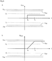
- FIG. 8a shows the input voltage U IN and FIG. 8b the corresponding output voltage U OUT of the operational amplifier OP FIG. 6 as a function of time.
- the operational amplifier OP is as in FIG. 6 shown connected as an integrator and the names correspond to those FIG. 7 ,
- the output voltage U OUT is essentially the time integral of the input voltage U IN . If no voltage difference exists between the inputs of the operational amplifier OP, the output voltage U OUT also remains constant. Occurring voltage differences are added up by the capacitor C and stored.
- FIG. 8a shows from a time t 0, a constant voltage difference between the inputs of the operational amplifier OP.
- the input voltage U IN is rectangular. This voltage difference is applied to the inverting input of the operational amplifier OP and corresponds, for example, the control deviation.
- the non-inverting input is grounded.
- the input voltage U IN outputs the operational amplifier OP linearly amplified as the output voltage U OFF .
- the capacitor C By the capacitor C, this is added up, so that it to the in FIG. 8b linearly increasing of the output voltage U OFF shown between t 0 and t 1 is coming.
- the capacitance of the capacitor C is dimensioned so that it is not exceeded in normal measurement operation.
- the capacity is unloaded in the event that there is no fault. If it is not possible to reduce this voltage difference at the input of the operational amplifier OP within a prescribed period of time due to, for example, a present defect in the measuring and operating electronics 1, the voltage difference is maintained and the output signal U OUT of the operational amplifier OP leaves the intended operating range and goes to the time t 1 in the saturation voltage U S1 via.
- the time span is determined by the capacitance C and the resistors R 1 , R 2 .
- the output voltage has different slopes between t 0 and t 1, depending on the magnitude of the voltage difference.
- the output signal of the operational amplifier OP is therefore transferred at different rates into the saturation voltage U S1 , U S2 . If the voltage difference between the inputs of the operational amplifier OP is outside the working range, the operational amplifier OP as the output voltage U off the saturation voltage U S1, U S2 (See FIG. 7 ).
Description
Die Erfindung bezieht sich auf ein Messgerät mit einer Mess- und Betriebselektronik, wobei die Mess- und Betriebselektronik zur Bestimmung und/oder Überwachung mindestens eines Messsignals einer physikalischen und/oder chemischen Messgröße eines Messstoffs dient, wobei die Mess- und Betriebselektronik mindestens eine Steuereinheit und einen Stromregler aufweist, wobei die Mess- und Betriebselektronik an eine Stromschleife angeschlossen ist, wobei ein Messsignalstrom in der Stromschleife einen Messwert der Messgröße repräsentiert, wobei die Steuereinheit mit dem Stromregler verbunden ist und dem Stromregler eine Führungsgröße vorgibt, wobei die Führungsgröße einem Sollwert des Messsignalstroms entspricht, wobei dem Stromregler eine Rückführgröße zugeführt ist, wobei die Rückführgröße einem in der Zwei-Leiter-Stromschleife eingestellten Istwert des Messsignalstroms entspricht, wobei die Rückführgröße und/oder die Führungsgröße an einem Eingang des Stromreglers anliegen, wobei der Stromregier eine aus einer Regelabweichung zwischen Rückführ- und Führungsgröße gebildete Stellgröße ausgibt.The invention relates to a measuring device with a measuring and operating electronics, wherein the measuring and operating electronics for determining and / or monitoring at least one measurement signal of a physical and / or chemical measurement of a medium used, the measuring and operating electronics at least one control unit and a current controller, wherein the measuring and operating electronics is connected to a current loop, wherein a measuring signal current in the current loop represents a measured value of the measured variable, wherein the control unit is connected to the current controller and the current controller specifies a reference variable, wherein the reference variable is a desired value of the measuring signal current corresponds, wherein the current controller, a feedback variable is supplied, wherein the feedback variable corresponds to a set in the two-wire current loop actual value of the measuring signal current, wherein the feedback variable and / or the reference variable at an input of the current controller s lie, wherein the Stromregier outputs a control variable formed from a control deviation between feedback and reference variable.
Ein in der Industrie weit verbreiteter Standard zur Übermittlung von Messsignalen einer physikalischen und/oder chemischen Messgröße ist eine elektrische Stromschleife. Hierbei entspricht ein in der Stromschleife eingestellter elektrischer Strom zwischen 4 Milliampere (mA) und 20 mA dem Messwert der physikalischen und/oder chemischen Messgröße.A widely used standard in the industry for the transmission of measurement signals of a physical and / or chemical measurand is an electrical current loop. In this case, an electric current set in the current loop between 4 milliamps (mA) and 20 mA corresponds to the measured value of the physical and / or chemical measured variable.
Aufgrund von Driften und Ungenauigkeiten wird ein etwas größerer Strombereich zugelassen; bspw. ein Strom zwischen 3,8 mA und 20,5 mA. Ströme die kleiner als 3,6 mA bzw. größer als 21 mA sind, sollten von etwaigen Auswerteeinheiten nicht mehr als eine dem Messwert entsprechende Größe interpretiert werden. Ein in der Stromschleife eingestellter Strom kleiner als 3,6 mA oder größer als 21 mA wird daher als Fehlerstrom identifiziert.Due to drifts and inaccuracies, a slightly larger current range is allowed; For example, a current between 3.8 mA and 20.5 mA. Currents which are smaller than 3.6 mA or greater than 21 mA should not be interpreted by any evaluation units as more than a value corresponding to the measured value. One in the current loop set current less than 3.6 mA or greater than 21 mA is therefore identified as fault current.
Feldgeräte, insbesondere Messgeräte, die nur einen Strombedarf von weniger als 3,6 mA haben, können aus der Stromschleife selbst mit Energie versorgt werden. Diese sog. Zwei-Leiter-Messgeräte (2L-Messgeräte) müssen über lediglich eine Leitung mit zwei Adern angeschlossen werden. Über die Zwei-Leiter-Stromschleife (2L-Stromschleife) ist das Feldgerät mit einer Stromquelle und/oder mit einer Prozessleitstelle verbunden. Feldgeräte mit einem höheren Stromverbrauch müssen mit einer zusätzlichen Hilfsenergie versorgt werden.Field devices, in particular measuring devices, which only have a power requirement of less than 3.6 mA, can be supplied with energy from the current loop itself. These so-called two-wire measuring devices (2L measuring devices) must be connected via only one line with two wires. The field device is connected to a current source and / or to a process control center via the two-conductor current loop (2L current loop). Field devices with a higher power consumption must be supplied with an additional auxiliary power.
Oft ist es erforderlich, außer dem analogen elektrischen Signal noch weitere Informationen, bspw. Kalibrier-, Parametrierdaten, Betriebstemperatur und -Spannung usw. über die 2L-Stromschleife zu übertragen. Um diese Informationen zu übertragen, wird das Messsignal von einem höherfrequenten Signal überlagert. Ein Protokoll zur Übertragung solcher Informationen ist bspw. das HART (Highway Adressabei Remote Transducer)-Protokoll.Often it is necessary, in addition to the analog electrical signal, to transmit further information, for example calibration, parameterization data, operating temperature and voltage, etc., via the 2L current loop. To transmit this information, the measurement signal is superimposed by a higher-frequency signal. One protocol for transmitting such information is, for example, the HART (Highway Address and Remote Transducer) protocol.
Der analoge, in der 2L-Stromschleife eingestellte Messsignalstrom wird meistens durch einen Regelkreis in der 2L-Stromschleife eingestellt. Dabei ist wenigstens ein Teil der Mess- und Betriebselektronik Teil des Regelkreises. Zum Zwecke der Regelung wird die dem Istwert des Messsignalstroms entsprechende Rückführgröße von der Mess- und Betriebselektronik zurückgelesen und mit der dem Sollwert entsprechenden Führungsgröße verglichen. Üblicherweise wird die Führungsgröße von einer Steuereinheit ausgegeben. Die Steuereinheit gibt entsprechend Messsignalen eines Messaufnehmers oder Sensors die Führungsgröße aus. Bei einer Messwertänderung unterscheidet sich der in der 2L-Stromschleife eingestellte Istwert vom Sollwert. Aus der Regelabweichung zwischen Ist- und Sollwert wird die entsprechende Stellgröße erzeugt, mittels derer der Messsignalstrom in der 2L-Stromschleife verändert wird.The analog measurement signal current set in the 2L current loop is usually set by a control circuit in the 2L current loop. At least part of the measuring and operating electronics is part of the control loop. For the purpose of regulation, the feedback variable corresponding to the actual value of the measuring signal current is read back from the measuring and operating electronics and compared with the reference variable corresponding to the desired value. Usually, the reference variable is output by a control unit. The control unit outputs the reference variable according to measurement signals of a sensor or sensor. If the measured value changes, the actual value set in the 2L current loop differs from the setpoint. From the control deviation between actual and setpoint, the corresponding manipulated variable is generated, by means of which the measuring signal current is changed in the 2L current loop.
Bei vielen Anwendungen kann die Größe des übermittelten Messsignals einen erheblichen Einfiluss auf die Umgebung des Messgerätes und/oder die Umwelt haben. Insbesondere bei chemischen und umweltgefährdenden Prozessen, bei denen ein Messwert der Temperatur, des Füllstands, des Drucks, des Durchflusses oder der Zusammensetzung eines Messstoffs übermittelt wird, ist ein sicherer Ablauf des Prozesses entscheidend. Daher ist es äußerst wichtig, dass das übermittelte Messsignal tatsächlich dem gemessen Messwert entspricht. Geräte und Systeme in sicherheitsrelevanten Anwendungen müssen daher besonderen Anforderungen genügen, u.a. die Normen zur funktionalen Sicherheit (z.B. IEC 61506, IEC 61511 etc.) erfüllen. Zentraler Bestandteil der Normen zur funktionalen Sicherheit ist das sog. Safety Integrity Level (SIL). Je nach der von einem Prozess oder einer Anlage ausgehenden Gefahr wird von einer Anwendung eine entsprechende SIL-Tauglichkeit gefordert. Das SIL gibt vor, mit welcher Wahrscheinlichkeit ein auftretender Fehler eines Gerätes oder einer Anwendung detektiert wird. Dabei wird zwischen einem SIL von 1 bis 4 unterschieden, wobei 1 die niedrigste und 4 die höchste Sicherheitsstufe angibt.In many applications, the size of the transmitted measurement signal may have a significant impact on the environment of the meter and / or the environment. In particular, in chemical and environmentally hazardous processes, in which a measured value of the temperature, the level, the pressure, the flow or the composition of a medium is transmitted, a safe process of the process is crucial. Therefore, it is extremely important that the transmitted measurement signal actually corresponds to the measured value. Devices and systems in safety-relevant applications must therefore meet special requirements, i.a. comply with functional safety standards (for example, IEC 61506, IEC 61511, etc.). A central component of functional safety standards is the so-called Safety Integrity Level (SIL). Depending on the risk posed by a process or plant, an application may require an appropriate SIL capability. The SIL specifies the probability with which an occurring error of a device or an application is detected. A distinction is made between an SIL of 1 and 4, where 1 indicates the lowest and 4 the highest security level.
Aus der Offenlegungsschrift
Weiterhin ist aus der Patentschrift
Der Erfindung liegt daher die Aufgabe zugrunde, ein kostengünstiges Messgerät mit einer verbesserten funktionalen Sicherheit vorzuschlagen.The invention is therefore based on the object to propose a cost-effective measuring device with improved functional safety.
Die Aufgabe wird erfindungsgemäß dadurch gelöst, dass mindestens eine Auswerteeinheit vorgesehen ist, dass die Auswerteeinheit mindestens einen vom Stromregler ausgegebenen Wert der Stellgröße mit mindestens einem Referenzwert vergleicht, dass der Vergleich angibt, ob der Wert der Stellgröße den Referenzwert über- oder unterschreitet. Die vorgeschlagene Auswerteeinheit ermöglicht es, das Abweichen der Stellgröße von einem Referenzwert oder das Über- oder Unterschreiten der Stellgröße über oder unter einen vorgegebenen Referenzwert zu detektieren. Sind insbesondere zwei unterschiedliche Referenzwerte vorgesehen, so ist feststellbar, ob die Stellgröße einen der Referenzwerte überschreitet oder unterschreitet oder in einem Bereich zwischen den Referenzwerten liegt. Das Ausgangssignals der Auswerteeinheit gibt an, ob die Stellgröße zwischen den Referenzwerten liegt oder einen oder beide Referenzwerte über- oder unterschreitet. Da sich Fehler oder Störungen der Mess- und Betriebselektronik oftmals in einem anormalen Messsignal äußern, bspw. durch übermäßige oder verminderte Spannungen und Ströme, ermöglicht die erfindungsgemäße Auswerteeinheit eine Detektion solcher anormalen Abweichungen.The object is achieved in that at least one evaluation unit is provided, that the evaluation unit compares at least one value output by the current controller of the manipulated variable with at least one reference value, that the comparison indicates whether the value of the manipulated variable exceeds the reference value or below. The proposed evaluation unit makes it possible to detect the deviation of the manipulated variable from a reference value or the above or below the manipulated variable above or below a predetermined reference value. If, in particular, two different reference values are provided, it can be determined whether the manipulated variable exceeds or falls below one of the reference values or lies in a range between the reference values. The output signal of the evaluation unit indicates whether the manipulated variable lies between the reference values or exceeds or falls below one or both reference values. Since faults or malfunctions of the measuring and operating electronics often manifest themselves in an abnormal measuring signal, for example due to excessive or reduced voltages and currents, the evaluation unit according to the invention makes it possible to detect such abnormal deviations.
Gemäß einer vorteilhaften Ausgestaltung gibt die Auswerteeinheit mindestens ein Ausgangssignal aus. Das Ausgangssignal gibt an, dass die Stellgröße einen vorgegebenen Referenzwert über- oder unterschritten hat. Ausgehend vom Ausgangssignal der Auswerteeinheit kann eine Abweichung oder ein Über- bzw. Unterschreiten der Stellgröße vom Referenzwert signalisiert oder entsprechende Maßnahmen ergriffen werden.According to an advantageous embodiment, the evaluation unit outputs at least one output signal. The output signal indicates that the manipulated variable has exceeded or fallen below a predetermined reference value. Starting from the output signal of the evaluation unit, a deviation or an overshoot or undershoot of the manipulated variable can be signaled from the reference value or appropriate measures can be taken.
Gemäß einer vorteilhaften Ausgestaltung weist das Messgerät bzw. die Mess- und Betriebselektronik ein Stellglied auf, wobei das Stellglied den Messsignalstrom mittels der vom Stromregler ausgegebenen Stellgröße in der Stromschleife einstellt. Dafür wird die vom Stromregler ausgegebene Stellgröße oder eine entsprechende Größe dem Stellglied, bspw. einem Transistor, über eine Ansteuerung zugeführt. Das Stellglied stellt daraufhin einen entsprechenden Messsignalstrom in der Stromschleife ein. Über das Stellglied werden auch die Stromzufuhr und der Energiebedarf der sonstigen Komponenten des Messgerätes und der Mess- und Betriebselektronik geregelt, die einer Energiezufuhr bedürfen. Die Stromschleife ist bspw. eine Zwei-Leiter-Stromschleife (2L-Stromschleife).According to an advantageous embodiment, the measuring device or the measuring and operating electronics has an actuator, wherein the actuator adjusts the measuring signal current by means of the control variable output by the current controller in the current loop. For this purpose, the control variable output by the current controller or a corresponding variable is supplied to the actuator, for example a transistor, via a drive. The actuator then sets a corresponding measurement signal current in the current loop. The actuator also controls the power supply and the energy requirements of the other components of the measuring device and of the measuring and operating electronics which require an energy supply. The current loop is, for example, a two-conductor current loop (2L current loop).
Gemäß einer vorteilhaften Weiterbildung ist die Steuereinheit die Auswerteeinheit oder Teil der Auswerteeinheit. Verfügt die Steuereinheit bspw. über einen analogen Eingang, so kann die Stellgröße direkt von der Steuereinheit ausgewertet werden. Dafür wird die vom Stromregler ausgegebene Stellgröße an die Steuereinheit übertragen. Die Auswertung, insbesondere der Vergleich der Stellgröße mit dem mindestens einen Referenzwert, wird mittels interner, in der Steuereinheit enthaltener Bauteile, Schaltungen und/oder Algorithmen ausgeführt. Über einen externen Analog/Digital - Umformer lässt sich die Stellgröße digitalisieren und so auch an einen digitalen Eingang der Steuereinheit leiten.According to an advantageous development, the control unit is the evaluation unit or part of the evaluation unit. If the control unit has, for example, an analog input, then the manipulated variable can be evaluated directly by the control unit. For this purpose, the control variable output by the current controller is transmitted to the control unit. The evaluation, in particular the comparison of the manipulated variable with the at least one reference value, is carried out by means of internal components, circuits and / or algorithms contained in the control unit. An external analog / digital converter can be used to digitize the manipulated variable and thus also to a digital input of the control unit.
Gemäß einer weiteren vorteilhaften Weiterbildung gibt die Auswerteeinheit das Ausgangssignal an die Steuereinheit aus. Insbesondere wenn die Auswerteeinheit nicht die Steuereinheit oder Teil der Steuereinheit ist, wird das von der Auswerteeinheit zur Verfügung gestellte Ausgangssignal der Steuereinheit zugeführt und die Steuereinheit wertet das Ausgangssignal aus und veranlasst geeignete Maßnahmen bspw. zur Erhaltung der Sicherheit.According to a further advantageous development, the evaluation unit outputs the output signal to the control unit. In particular if the evaluation unit is not the control unit or part of the control unit, the output signal provided by the evaluation unit is supplied to the control unit and the control unit evaluates the output signal and initiates suitable measures, for example to maintain safety.
Gemäß einer weiteren vorteilhaften Weiterbildung weist der Stromregler mindestens ein Vergleichsglied auf, wobei das Vergleichsglied die Regelabweichung bestimmt. Das Vergleichsglied ist eine Funktionseinheit, die aus der Führungs- und der Rückführgröße die Regelabweichung bestimmt. Die Regelabweichung ist bspw. die Differenz zwischen der dem Istwert des Messsignalstrams entsprechenden Rückführgröße und der dem Sollwert des Messsignalstroms entsprechenden Führungsgröße.According to a further advantageous development, the current regulator has at least one comparison element, wherein the comparison element the Control deviation determined. The comparison element is a functional unit that determines the control deviation from the control and feedback variables. The control deviation is, for example, the difference between the feedback value corresponding to the actual value of the measurement signalstram and the reference variable corresponding to the desired value of the measurement signal current.
Gemäß einer weiteren vorteilhaften Weiterbildung weist der Stromregier mindestens einen Operationsverstärker auf. Je nach Wahl und Schaltung der Bauelemente kann der Operationsverstärker verschiedene lineare und nichtlineare Operationen durchführen, wie etwa verstärken, logarithmieren oder integrieren, mehrere Signale vergleichen, addieren, subtrahieren oder als Schwellwertschalter, insbesondere Komparator, dienen. Die mittels dieser Operationen gebildeten Größen können als Stellgröße für den zu regelnden Messsignalstrom dienen. Der Operationsverstärker gleicht bei geeigneter Beschaltung die Differenz zwischen dem an seinem invertierenden Eingang anliegenden Signal und dem an seinem nicht invertierenden Eingang anliegenden Signal beinahe instantan aus und gibt die Differenz verstärkt aus.According to a further advantageous development, the current regulator has at least one operational amplifier. Depending on the choice and circuit of the devices, the operational amplifier may perform various linear and non-linear operations, such as amplify, logarithm or integrate, compare, add or subtract multiple signals, or serve as a threshold, in particular comparator. The variables formed by these operations can serve as a manipulated variable for the measured signal current to be regulated. The operational amplifier, with suitable circuitry, compensates for the difference between the signal applied to its inverting input and the signal present at its non-inverting input almost instantaneously and amplifies the difference.
Gemäß einer weiteren vorteilhaften Weiterbildung ist das Vergleichsglied elektrisch mit einem Eingang des Operationsverstärkers verbunden, und der Operationsverstärker erzeugt ausgehend von der Regelabweichung die Stellgröße und gibt die Stellgröße aus. Die Regelabweichung kann bspw. durch Zusammenführen der Rückführgröße und der Führungsgröße an einem Summationspunkt ermittelt werden. Ein Summationspunkt ist ein Knotenpunkt eines elektrischen Netzwerks. Das vom Summationspunkt abgeführte Signal entspricht dann bspw. der Differenz zwischen Führungs- und Rückführgröße. Dabei ist die Führungs- und/oder die Rückführgröße eine dem Ist- und/oder dem Sollwert entsprechende elektrische Spannung oder ein elektrischer Strom. Die vom Summationspunkt in den Operationsverstärker ausgegebene Regelabweichung ist dann die Spannungsdifferenz zwischen Führungs- und Rückführgröße. Der Operationsverstärker ist bspw. als invertierender Verstärker beschaltet. Die Regelabweichung liegt an einem ersten Eingang des Operationsverstärkers an und an einem zweiten Eingang liegt eine Referenzspannung bspw. die Masse (0 V) oder ein geeignetes Bezugspotential an. Der erste Eingang ist der invertierende und der zweite der nicht invertierende Eingang des Operationsverstärkers. Bei einer solchen Beschaltung gibt der Operationsverstärker die Differenz der Regelabweichung vom Bezugspotential als Stellgröße aus.According to a further advantageous development, the comparison element is electrically connected to an input of the operational amplifier, and the operational amplifier generates the manipulated variable starting from the control deviation and outputs the manipulated variable. The control deviation can be determined, for example, by merging the feedback variable and the reference variable at a summation point. A summation point is a node of an electrical network. The signal removed from the summation point then corresponds, for example, to the difference between the command and feedback variables. The control and / or the feedback variable is an electrical voltage or an electric current corresponding to the actual and / or the desired value. The control deviation output from the summation point to the operational amplifier is then the voltage difference between the command and feedback variables. The operational amplifier is, for example, connected as an inverting amplifier. The control deviation is at a first input of the operational amplifier at and at a second input is a reference voltage, for example, the ground (0 V) or a suitable reference potential. The first input is the inverting and the second is the non-inverting input of the operational amplifier. In such a circuit, the operational amplifier outputs the difference of the control deviation from the reference potential as a manipulated variable.
Gemäß einer weiteren vorteilhaften Weiterbildung ist der Operationsverstärker mit einer Betriebsspannung versorgt und weist einen Arbeitsbereich auf, wobei der Arbeitsbereich unterhalb der Betriebspannung liegt. Der Operationsverstärker wird oft symmetrisch mit zwei identischen Gleichspannungen betrieben, bspw. ±5 V, ±12 V und ±15 V. Möglich ist auch eine Beschaltung des ersten Betriebsanschlusses mit nur einer Gleichspannung. Der zweite Betriebsanschluss ist dann mit der Masse oder dem Bezugspotential verbunden. Der Arbeitsbereich des Operationsverstärkers liegt zwischen der oberen Betriebsspannung und der unteren Betriebsspannung. Dabei ist der Arbeitsbereich so ausgelegt, dass die Stellgröße im Falle einer fehlerfreien Mess- und Betriebselektronik bzw. eines fehlerfreien Messsignals innerhalb des Arbeitsbereichs des Operationsverstärkers liegt. Weiterhin ist der Arbeitsbereich so ausgelegt, dass die Stellgröße einen Messsignalstrom zwischen bspw. 4 mA und 20 mA einstellt, ohne den Arbeitsbereich des Operationsverstärker zu verlassen. Eine Messwertänderung vom minimalen Messwert zum maximalen Messwert entspricht dann einer Änderung des Messsignalstroms, von dem Messsignalstrom der den minimalen Messwert repräsentiert, zu dem Messsignalstrom der den maximalen Messwert repräsentiert, also bspw von 4 mA auf 20 mA oder 3,8 auf 20,5 mA. Der Arbeitsbereich und die Funktionsweise des Operationsverstärkers sind so ausgelegt, dass der Operationsverstärker seinen Arbeitsbereich selbst bei einer maximalen Messwertänderung nicht oder nur kurzzeitig (für Zeitspannen im Millisekundenbereich) verlässt.According to a further advantageous development of the operational amplifier is supplied with an operating voltage and has a working range, wherein the working range is below the operating voltage. The operational amplifier is often operated symmetrically with two identical DC voltages, for example ± 5 V, ± 12 V and ± 15 V. It is also possible to connect the first operating connection with only one DC voltage. The second operating connection is then connected to the ground or the reference potential. The operating range of the operational amplifier is between the upper operating voltage and the lower operating voltage. In this case, the working range is designed so that the manipulated variable is within the working range of the operational amplifier in the case of a faultless measuring and operating electronics or a fault-free measuring signal. Furthermore, the working range is designed so that the manipulated variable sets a measuring signal current between, for example, 4 mA and 20 mA, without leaving the working range of the operational amplifier. A change in measured value from the minimum measured value to the maximum measured value then corresponds to a change in the measuring signal current, from the measuring signal current representing the minimum measured value to the measuring signal current representing the maximum measured value, for example from 4 mA to 20 mA or 3.8 to 20.5 mA , The operating range and the mode of operation of the operational amplifier are designed in such a way that the operational amplifier does not leave its working range even for a maximum measured value change, or only for a short time (for periods in the millisecond range).
Gemäß einer weiteren vorteilhaften Weiterbildung verlässt die Stellgröße den Arbeitsbereich des Operationsverstärkers, im Falle, dass die Differenz zwischen Führungsgröße und Rückführgröße nach einer vorgegebenen Zeitspanne nicht annähernd Null ist. Im fehlerfreien Regelbetrieb gibt die Steuereinheit die Führungsgröße aus, wobei die Führungsgröße dem Sollwert des Messsignalstroms entspricht. Die Führungs- und die Rückführgröße wird an den Stromregler übermittelt. Die Rückführgröße entspricht dem Istwert des in der 2L-Stromschleife eingestellten Messsignalstroms. Bei einer einzustellenden Messwertänderung sind Rückführgröße und Führungsgröße respektive Ist- und Sollwert nicht identisch und am Eingang des Operationsverstärkers liegt eine Regelabweichung ungleich Null an. Der Operationsverstärker gibt eine der Regelabweichung entsprechende Stellgröße nahezu instantan aus. Die Verzögerungszeit liegt typischerweise im Mikrosekundenbereich (10-6 s). Dem entsprechend stellt sich in der 2L-Stromschleife die Führungsgröße ein und die Regelabweichung zwischen Ist- und Sollwert geht gegen Null. Liegt hingegen ein Fehler oder Defekt vor, so verschwindet die Regelabweichung nicht, sondern es liegt weiterhin eine Spannungsdifferenz zwischen den Eingängen des Operationsverstärkers vor. Da der als Stromregler fungierende Operationsverstärker die Spannungsdifferenz nicht ausgleichen kann, übersteuert er und verlässt seinen Arbeitsbereich. Die Zeitspanne nach der der Operationsverstärker seinen Arbeitsbereich verlässt, wird durch die Charakteristiken der verwendeten Bauteile, wie bspw. Operationsverstärker, Kondensatoren und Widerstände, bestimmt.According to a further advantageous development, the manipulated variable leaves the operating range of the operational amplifier, in the event that the difference between the reference variable and feedback variable is not nearly zero after a predetermined period of time. In error-free control mode, the control unit outputs the reference variable, wherein the reference variable corresponds to the desired value of the measurement signal current. The command and feedback quantities are transmitted to the current controller. The feedback quantity corresponds to the actual value of the measurement signal current set in the 2L current loop. For a measured value change to be set, the feedback variable and the reference variable or actual and setpoint are not identical, and a control deviation not equal to zero is present at the input of the operational amplifier. The operational amplifier outputs a manipulated variable corresponding to the control deviation virtually instantaneously. The delay time is typically in the microsecond range (10 -6 s). Accordingly, the reference variable is established in the 2L current loop and the control deviation between actual and setpoint approaches zero. On the other hand, if there is an error or defect, the control deviation does not disappear, but there is still a voltage difference between the inputs of the operational amplifier. Since the operational amplifier functioning as a current regulator can not compensate for the voltage difference, it overdrives and leaves its working range. The time span after which the operational amplifier leaves its operating range is determined by the characteristics of the components used, such as operational amplifiers, capacitors and resistors.
Gemäß einer weiteren vorteilhaften Weiterbildung ist, im Falle dass die Stellgröße außerhalb des Arbeitsbereichs des Operationsverstärkers liegt, die Stellgröße annähernd gleich der Betriebsspannung des Operationsverstärkers. Verlässt der Operationsverstärker seinen Arbeitsbereich aufgrund einer vorhandenen Spannungsdifferenz zwischen den an seinen Eingängen anliegenden Signalen und kann der Operationsverstärker die Spannungsdifferenz nicht ausgleichen, so geht der Operationsverstärker in seinen (oberen oder unteren) Sättigungsbereich über. Der Sättigungsbereich entspricht dabei annähernd der (oberen oder unteren) Betriebsspannung des Operationsverstärkers, wobei die Sättigungsspannung von der Betriebsspannung abweicht, da bei einem realen Operationsverstärker Spannungs- und anderweitige Verluste auftreten.According to a further advantageous embodiment, in the case that the manipulated variable is outside the operating range of the operational amplifier, the manipulated variable approximately equal to the operating voltage of the operational amplifier. Leaves the operational amplifier his work area due to an existing voltage difference between the signals applied to its inputs and the operational amplifier can not compensate for the voltage difference, so goes Operational amplifier in its (upper or lower) saturation range over. The saturation region corresponds approximately to the (upper or lower) operating voltage of the operational amplifier, wherein the saturation voltage deviates from the operating voltage, since in a real operational amplifier voltage and other losses occur.
Gemäß einer weiteren vorteilhaften Weiterbildung liegt der mindestens eine Referenzwert oberhalb bzw. unterhalb des Arbeitsbereichs des Stromreglers. Durch eine solche Belegung der Referenzwerte werden Abweichungen der Stellgröße aus dem Arbeitsbereich detektiert.According to a further advantageous development, the at least one reference value is above or below the working range of the current controller. By occupying the reference values, deviations of the manipulated variable from the working range are detected.
Gemäß einer weiteren vorteilhaften Weiterbildung besteht die Auswerteeinheit teilweise aus einer Komparatorschaltung und/oder einem Analog-Digital-Umformer. Eine Komparatorschaltung bspw. ein geeignet beschalteter Operationsverstärker dient dem Vergleich der Stellgröße mit einem Referenzwert. Der Referenzwert kann aus der Betriebsspannung des im Stromregler enthaltenen Operationsverstärkers bspw. mittels Spannungsteilern abgeleitet werden. Der Komparator vergleicht dann den Wert der Stellgröße mit dem Referenzwert und erzeugt ein entsprechendes Ausgangssignal. Zusätzlich oder alternativ ist ein Analog/Digital-Umformer vorgesehen, der die Stellgröße digitalisiert und ein entsprechendes Ausgangssignal zur Weiterverarbeitung ausgibt. Weiterhin kann ein digitaler Komparator vorgesehen sein, der die digitalisierte Stellgröße mit einem ebenso in digitaler Form vorliegendem Referenzwert vergleicht und einen entsprechenden Wert oder ein Signal als Ausgangssignal zur Verfügung stellt.According to a further advantageous development, the evaluation unit partially consists of a comparator circuit and / or an analog-to-digital converter. A comparator circuit, for example, a suitably wired operational amplifier is used to compare the manipulated variable with a reference value. The reference value can be derived from the operating voltage of the operational amplifier contained in the current regulator, for example by means of voltage dividers. The comparator then compares the value of the manipulated variable with the reference value and generates a corresponding output signal. Additionally or alternatively, an analog / digital converter is provided which digitizes the manipulated variable and outputs a corresponding output signal for further processing. Furthermore, a digital comparator may be provided which compares the digitized manipulated variable with a reference value also present in digital form and provides a corresponding value or a signal as an output signal.
Gemäß einer weiteren vorteilhaften Weiterbildung ist das von der Auswerteeinheit erzeugte Ausgangssignal ein digitales Signal. Durch ein digitales Ausgangssignal ist eine Weiterleitung und Weiterverarbeitung des Ausgangssignals an einen digitalen Schaltkreis, bspw. einen integrierten Schaltkreis insbesondere eine CPU oder ein ASIC möglich.According to a further advantageous development, the output signal generated by the evaluation unit is a digital signal. By means of a digital output signal, a forwarding and further processing of the output signal to a digital circuit, for example an integrated circuit, in particular a CPU or an ASIC, is possible.
Gemäß einer weiteren vorteilhaften Weiterbildung besteht das Ausgangssignal aus einem Bit oder aus n-Bits, wobei n eine natürliche Zahl größer eins ist. Ein analoger Komparator stellt bspw. ein solches aus einem Bit bestehendes Ausgangssignal zur Verfügung. In der Auswerteeinheit kann ein Analog/Digital-Umformer vorgesehen sein. Ein solcher Analog/Digital-Umformer erzeugt ein aus n Bits bestehendes Ausgangssignal.According to a further advantageous development, the output signal consists of one bit or n bits, where n is a natural number greater than one. An analogue comparator provides, for example, such an output signal consisting of one bit. In the evaluation, an analog / digital converter may be provided. Such an analog-to-digital converter generates an output signal consisting of n bits.
Gemäß einer weiteren vorteilhaften Weiterbildung gibt die Steuereinheit ein dem Ausgangssignal der Auswerteeinheit entsprechendes Signal, insbesondere ein Fehlersignal, aus. Ausgehend vom Ausgangssignal der Auswerteeinheit, das bspw. der Steuereinheit zugeführt wird, wird ein entsprechendes Signal an die weitere Mess- und Betriebselektronik gesendet. Dabei kann es sich bspw. um ein OK-Signal, ein Fehler-Signal oder ein sonstiges Steuer- oder Regelsignal handeln. Das entsprechende Signal. insbesondere das Fehlersignal, wird bspw. nur dann ausgelöst, wenn die Stellgröße einen der Referenzwerte über- bzw. unterschreitet. Das Fehlersignal löst, dann bspw. einen Fehlerstrom in der 2L-Stromschleife aus. Je nach Fehlersignal kann es sich dabei um einen High- oder Low-Alarm handeln, d.h. einen Fehlerstrom von mehr als 20,5 mA oder weniger als 3,6 mA.According to a further advantageous development, the control unit outputs a signal corresponding to the output signal of the evaluation unit, in particular an error signal. Starting from the output signal of the evaluation unit, which is supplied, for example, to the control unit, a corresponding signal is sent to the further measuring and operating electronics. This may, for example, be an OK signal, an error signal or another control or regulating signal. The corresponding signal. In particular, the error signal is, for example, only triggered when the manipulated variable exceeds or falls below one of the reference values. The error signal triggers, then, for example, a fault current in the 2L current loop. Depending on the error signal, this may be a high or low alarm, i. a fault current greater than 20.5 mA or less than 3.6 mA.
Gemäß einer weiteren vorteilhaften Weiterbildung gibt die Steuereinheit das Fehlersignal aus, wenn die Stellgröße den Referenzwert länger als eine vorgegebene Zeitspanne, insbesondere annähernd eine Sekunde, über- oder unterschreitet. Bei der Regelung des Messsignalstroms kann es zu kurzzeitigen, nicht durch einen Fehler verursachten, Über- oder Unterschreitungen des/der Referenzwerte/s kommen. Die vorgegebene Zeitspanne, nach der ein Fehlersignal ausgegeben wird, kann bspw. entsprechend einer NAMUR-Empfehlung, eines Standards oder einer vorgeschriebenen Norm gewählt werden.According to a further advantageous development, the control unit outputs the error signal when the manipulated variable exceeds or falls short of the reference value for longer than a predetermined period of time, in particular approximately one second. When regulating the measuring signal current, short-term, not caused by an error, overruns or underruns of the reference value (s) may occur. The predetermined period of time after which an error signal is output can, for example, be selected according to a NAMUR recommendation, a standard or a prescribed standard.
Die erfindungsgemäße Schaltung ermöglicht es u.a. Fehler, die von
- einer falschen oder fehlerhaften Spezifikation der Systemkomponenten,
- der Hardware oder der Software;
- einem statistischen Hardware Fehler oder Ausfall;
- einen systematischen Hardware oder Software Fehler;
- einem menschlichen Fehler;
- Umwelteinflüssen, insbesondere atmosphärischen, elektromagnetischen, kalorimetrischen und/oder mechanischen Einflüssen;
- Störungen des Versorgungssystems z.B. Spannungsschwankungen oder Spannungsverlust
- a wrong or incorrect specification of the system components,
- the hardware or the software;
- a statistical hardware failure or failure;
- a systematic hardware or software error;
- a human error;
- Environmental influences, in particular atmospheric, electromagnetic, calorimetric and / or mechanical influences;
- Disruptions of the supply system eg voltage fluctuations or voltage loss
Eine weitere Möglichkeit zur Übermittlung von Messsignalen sind serielle Feldbus-Systeme z.B. Profibus PA und Foundation Fieldbus FF. Diese werden oftmals auch als 2-Leiter-Feldgeräte, insbesondere 2L-Messgeräte, realisiert, bei denen die Energieversorgung aus der Stromschleife sichergestellt wird. Im Gegensatz zu 2L-Messgeräten mit Stromschleife (z.B. mit einem einen Messwert repräsentierenden Messsignalstrom zwischen 4 und 20mA) ist der eingestellte Strom konstant, entspricht also nicht dem Messwert. Mess- und Steuersignale werden z.B. mittels Manchester-Codierung digital übertragen. D.h. auch die Feldbussysteme sind mit einem Stromregler ausgestattet. Dieser Wert muss zur Dimensionierung des Bussystems bekannt sein, da die Energieversorgung für mehrere Geräte gemeinsam erfolgt. Ein fehlerhafter Strom kann dazu führen, dass das ganze Bussystem ausfällt oder unstabil wird. Es ist also vorteilhaft den eingestellten Strom zu überwachen. Die Funktionsweise der Stromüberwachung erfolgt wie bei der oben beschriebenen Stromschleife.Another possibility for transmitting measurement signals are serial fieldbus systems, e.g. Profibus PA and Foundation Fieldbus FF. These are often also realized as 2-wire field devices, in particular 2L measuring devices, in which the power supply from the current loop is ensured. In contrast to 2L meters with current loop (for example with a measuring signal current between 4 and 20mA representing a measured value), the set current is constant, ie it does not correspond to the measured value. Measuring and control signals are e.g. transmitted digitally using Manchester coding. That The fieldbus systems are also equipped with a current regulator. This value must be known for dimensioning the bus system, since the power supply for several devices is shared. A faulty current can cause the entire bus system to fail or become unstable. It is therefore advantageous to monitor the set current. The operation of the current monitoring takes place as in the current loop described above.
Die Erfindung wird anhand der nachfolgenden Zeichnungen näher erläutert. Es zeigt:
-
Fig. 1 : eine schematische Darstellung eines Schaltplans einer ersten Ausführungsform der erfindungsgemäßen Mess- und Betriebselektronik, -
Fig. 2 : eine schematische Darstellung eines Schaltplans einer zweiten Ausführungsform der erfindungsgemäßen Mess- und Betriebselektronik, -
Fig. 3 : eine schematische Darstellung eines Schaltplans einer dritten Ausführungsform der erfindungsgemäßen Mess- und Betriebselektronik, -
Fig. 4 : eine schematische Darstellung eines Schaltplans einer Ausführungsform der erfindungsgemäßen Mess- und Betriebselektronik bei einem Vier-Leiter-Gerät, -
Fig. 5 : eine schematische Darstellung eines Schaltplans einer weiteren Ausführungsform der erfindungsgemäßen Mess- und Betriebselektronik bei einem Vier-Leiter-Gerät, -
Fig. 6 : eine schematische Darstellung eines Stromreglers, -
Fig. 7 : eine schematische Darstellung des Arbeitsbereichs und der Betriebsspannung eines Operationsverstärkers, und -
Fig. 8 : Eingangs- und Ausgangssignal eines als Integrator beschalteten Operationsverstärkers.
-
Fig. 1 : a schematic representation of a circuit diagram of a first embodiment of the measuring and operating electronics according to the invention, -
Fig. 2 : a schematic representation of a circuit diagram of a second embodiment of the measuring and operating electronics according to the invention, -
Fig. 3 : a schematic representation of a circuit diagram of a third embodiment of the measuring and operating electronics according to the invention, -
Fig. 4 : a schematic representation of a circuit diagram of an embodiment of the measurement and operating electronics according to the invention in a four-wire device, -
Fig. 5 FIG. 2 shows a schematic illustration of a circuit diagram of a further embodiment of the measuring and operating electronics according to the invention in a four-wire device, FIG. -
Fig. 6 : a schematic representation of a current regulator, -
Fig. 7 a schematic representation of the operating range and the operating voltage of an operational amplifier, and -
Fig. 8 : Input and output signal of an operational amplifier connected as an integrator.
Die Mess- und Betriebselektronik 1 ist Teil eines Messgerätes, das an die 2L-Stromschleife angeschlossen ist. Das Messgerät ist bspw. ein Feldgerät und/oder ein Messgerät der Prozessautomatisierungstechnik, das zur Aufnahme eines Drucks, eines Füllstands, eines Durchflusses, einer Temperatur und/oder einer Analyse eines Messstoffs dient.The measuring and
Die gezeigte Ausgangsschaltung ist Teil der Mess- und Betriebselektronik 1 und besteht im Wesentlichen aus einem Regelstromkreis, der den in der 2L-Stromschleife eingestellten Strom regelt. Der Regelstromkreis besteht im Wesentlichen aus einer Steuereinheit IC, einem Stromregler SR, einem Stellglied SG, einer Ansteuerung A des Stellglieds SG und den Anschlüssen A1, A2 an die 2L-Stromschleife und der - nicht explizit gezeigten - 2L-Stromschleife.The output circuit shown is part of the measuring and
An die gezeigte Mess- und Betriebselektronik 1 ist die eigentliche Versorgungselektronik des Messgerätes angeschlossen. Die Versorgungselektronik ist in
Das elektrische Messsignal wird einer Steuereinheit IC zugeführt. Die Steuereinheit ist bspw. eine Central Processing Unit (CPU) oder ein Application Specific Integrated Circuit (ASIC). Ein Bestandteil der Steuereinheit IC kann eine Speichereinheit bspw. in Form einer Read Only Memory (ROM)- oder Random Access Memory (RAM)-Einheit sein.The electrical measurement signal is fed to a control unit IC. The control unit is, for example, a central processing unit (CPU) or a Application Specific Integrated Circuit (ASIC). A component of the control unit IC may be a memory unit, for example in the form of a read only memory (ROM) or random access memory (RAM) unit.
Das der Steuereinheit IC zugeführte Messsignal wird von dieser verarbeitet und eine entsprechende Führungsgröße USOLL ausgegeben. Die Führungsgröße USOLL entspricht dem in der 2L-Stromschieife einzustellenden Sollwert des Messsignalstroms. Das von der Steuereinheit IC empfangene Messsignal ist ein digitales oder analoges Signal. Bei dem von der Steuereinheit ausgegebenen Sollwert handelt es sich um ein analoges Spannungssignal. Die Steuereinheit ist mit dem Stromregler verbunden und überträgt die Führungsgröße USOLL an einen Eingang des Stromreglers.The measurement signal supplied to the control unit IC is processed by the latter and a corresponding reference variable U SOLL is output. The reference variable U SOLL corresponds to the setpoint value of the measurement signal current to be set in the 2L current loop. The measurement signal received by the control unit IC is a digital or analog signal. The setpoint output by the control unit is an analog voltage signal. The control unit is connected to the current controller and transmits the reference variable U SOLL to an input of the current controller.
Der in der 2L-Stromschleife eingestellte Messsignalstrom bzw. ein aus dem Messsignalstrom abgeleitetes Signal wird dem Stromregler SR als Rückführgröße UIST zugeführt. Die Rückführgröße UIST entspricht einem in der 2L-Stromschleife eingestellten Istwert des Messsignalstroms. Dafür wird der Messsignalstrom zurückgelesen und die Rückführgröße ebenfalls an einen Eingang des Stromreglers SR geleitet. Die Rückführgröße UIST ist bspw. eine dem Istwert entsprechende Spannung.The measurement signal current set in the 2L current loop or a signal derived from the measurement signal current is supplied to the current regulator SR as feedback variable U actual . The feedback quantity U IST corresponds to an actual value of the measurement signal current set in the 2L current loop. For this, the measuring signal current is read back and the feedback variable is also sent to an input of the current regulator SR. The feedback variable U IST is, for example, a voltage corresponding to the actual value.
Es ist wenigstens ein Messwiderstand M vorgesehen, über den eine dem Istwert des Messsignalstroms entsprechende Spannung abfällt.At least one measuring resistor M is provided, via which a voltage corresponding to the actual value of the measuring signal current drops.
Führungsgröße USOLL und Rückführgröße UIST des Messsignalstroms sind bspw. an denselben Eingang oder an verschiedene Eingänge des Stromreglers SR angelegt. Dies ist von dem konkreten Aufbau und der Funktionsweise des Stromreglers SR abhängig.
Der Stromregler SR leitet aus der Führungsgröße USOLL und der Rückführgröße UIST eine Regelabweichung ab. Bei der Regelabweichung handelt es sich bspw. um die Differenz zwischen Führungsgröße USOLL und Rückführgröße UIST. Ein einfacher Stromregler SR kann somit mittels eines geeignet beschalteten Operationsverstärkers OP realisiert werden. Ein solcher Stromregler SR wird mit mindestens einer Betriebspannung UEE, UCC versorgt und weist einen Arbeitsbereich auf. Der Arbeitsbereich und die elektronische Schaltung sind dabei so ausgelegt, dass ein einem Messwert entsprechender Messsignalstrom von der Stellgröße geregelt werden können, wobei die Stellgröße dabei innerhalb des Arbeitsbereichs liegt.The current controller SR derives a control deviation from the reference variable U SOLL and the feedback variable U IST . At the control deviation is, for example, the difference between the reference variable U SOLL and the feedback variable U IST . A simple current regulator SR can thus be realized by means of a suitably connected operational amplifier OP. Such a current regulator SR is supplied with at least one operating voltage U EE , U CC and has a working area. The working range and the electronic circuit are designed so that a measured value corresponding to a measured signal current can be controlled by the manipulated variable, wherein the manipulated variable is within the working range.
Diese vom Stromregler SR ausgegebene Stellgröße wird an die Ansteuerung A des Stellglieds SG übertragen, die das Stellglied SG, bspw. einen Ausgangstransistor, entsprechend steuert. Das Stellglied SG stellt dann einen Messsignalstrom in der 2L-Stromschleife ein.This control variable output by the current controller SR is transmitted to the control A of the actuator SG, which controls the actuator SG, for example. An output transistor accordingly. The actuator SG then adjusts a measurement signal current in the 2L current loop.
Erfindungsgemäß wird die vom Stromregler SR ausgegebene Stellgröße einer Auswerteeinheit 10 zugeführt. In
Der Stromregler SR besteht im Wesentlichen aus einem Operationsverstärker OP, der mit einer Betriebsspannung UEE bzw. UCC versorgt wird. Der Stromregler SR erzeugt eine Stellgröße, die den von dem Ausgangstransistor SG einzustellende Messsignalstrom bestimmt. Bei fehlerfreiem Betrieb liegt die Stellgröße innerhalb des Arbeitsbereichs des Operationsverstärkers OP. Verlässt die Stellgröße den Arbeitsbereich, wird dies von den Komparatoren K1, K2 der Auswerteeinheit 10 durch ein entsprechendes Ausgangssignal signalisiert. Das entsprechende Ausgangssignal ist eine von den Komparatoren K1, K2 ausgegebene Spannung. Der Stromregier zeigt einen Fehler dadurch an, dass er seinen für den Regelbetrieb vorgesehenen Arbeitsbereich verlässt. In
Der Arbeitsbereich des Operationsverstärkers OP ist gerade so eingestellt, dass er einen Messsignalstrom in der 2L-Stromschleife innerhalb einer vorgegebenen Zeit (üblicherweise im Millisekundenbereich) regelt. Kurzzeitig kann es dabei zu Überschreitungen des Arbeitsbereichs kommen.The operating range of the operational amplifier OP is currently set to control a measurement signal current in the 2L current loop within a predetermined time (usually in the millisecond range). For a short time, the work area may be exceeded.
Das Stellglied SG stellt die vom Stromregler SR ausgegebene Stellgröße in der 2L-Stromschleife ein. Istwert und Sollwert des Messsignalstroms und daher auch Führungs- USOLL und Rückführgröße UIST stimmen anschließend überein.The actuator SG adjusts the manipulated variable output by the current regulator SR in the 2L current loop. Value and setpoint of the measuring signal current and therefore management U DES and feedback signal U ACT then match.
Liegt dagegen ein Defekt, eine Störung oder ein sonstiger Fehler vor, so unterscheidet sich die Führungsgröße USOLL dauerhaft von der Rückführgröße UIST. Der Stromregler SR versucht diese Regelabweichung auszugleichen und übersteuert dabei, da die vom Fehler verursachte Regelabweichung nicht durch eine Änderung der Stellgröße ausgeglichen wird. Der Operationsverstärker OP des Stromreglers SR geht in seine Sättigungsspannung über. Je nachdem, ob eine positive oder negative Differenz zwischen Führungs- UIST und Rückführgröße USOLL vorliegt, geht der Operationsverstärker OP in die obere oder untere Sättigungsspannung über.
Die Stellgröße wird abgegriffen und der Auswerteschaltung, die zwei Komparatoren K1, K2 umfasst, zugeführt. Die zwei Komparatoren K1, K2 vergleichen die Stellgröße mit jeweils einem Referenzwert S1, S2. Dafür wird an den Komparator K1 ein Referenzwert S1 angelegt, der über dem Arbeitsbereich des Operationsverstärkers OP liegt. Am zweiten Komparator K2 wird die Stellgröße mit einem Referenzwert S2 verglichen, der unterhalb des Arbeitsbereichs des Operationsverstärkers OP liegt. Je nachdem ob die Stellgröße oberhalb oder unterhalb des Referenzwertes S1, S2 liegt, geht der aus einem Operationsverstärker OP bestehende Komparator K1, K2 in seinen oberen oder unteren Sättigungsbereich. Abhängig von der ausgegebenen Sättigungsspannung lässt sich feststellen, ob die Stellgröße oberhalb, unterhalb oder innerhalb des von den Referenzwerten S1, S2 vorgegebenen Bereichs liegt. Die von den Komparatoren K1, K2 ausgegebenen Signale besitzen digitalen Charakter, so dass mittels der Signale eine Digitalschaltung angesprochen werden kann. Diese ein Bit wertigen digitalen Signale werden der Steuereinheit IC zugeführt.The manipulated variable is tapped and fed to the evaluation circuit, which comprises two comparators K1, K2. The two comparators K1, K2 compare the manipulated variable, each with a reference value S1, S2. For this purpose, a reference value S1 is applied to the comparator K1, which lies above the operating range of the operational amplifier OP. At the second comparator K2, the manipulated variable is compared with a reference value S2, which is below the operating range of the operational amplifier OP. Depending on whether the manipulated variable is above or below the reference value S1, S2, the comparator K1, K2 consisting of an operational amplifier OP goes into its upper or lower saturation region. Depending on the output saturation voltage, it can be determined whether the manipulated variable is above, below or within the range specified by the reference values S1, S2. The signals output by the comparators K1, K2 have a digital character, so that a digital circuit can be addressed by means of the signals. These one-bit-valued digital signals are supplied to the control unit IC.
Möglich ist auch die Verwendung einer Speichereinheit bspw. einer RAM oder ROM, die mit einer Steuereinheit IC kommuniziert. Die Steuereinheit IC fragt die Stellgröße entsprechend einer Überwachungsroutine ab und wertet sie aus. Liegt die Stellgröße bspw. länger als 1s außerhalb des Arbeitsbereichs, so wird ein Fehlersignal ausgegeben und ein Fehlerstrom in der 2L-Stromschleife eingestellt.It is also possible to use a memory unit, for example a RAM or ROM, which communicates with a control unit IC. The control unit IC queries the manipulated variable according to a monitoring routine and evaluates it. If, for example, the manipulated variable is outside the working range for longer than 1 s, an error signal is output and a fault current is set in the 2L current loop.
Ein fehlerhafter Messsignaistrom in der 2L-Stromschleife kann sich u.a. aufgrund einer Beschädigung der elektrischen Leiterbahnen oder einer mangelhaften Spannungsversorgung einstellen. Die Defekte werden oftmals durch korrosive Einflüsse aus der Umgebung des Messgerätes oder fehlerhafte Lötstellen ausgelöst.A faulty measurement signal current in the 2L current loop may be caused i.a. due to damage to the electrical tracks or a faulty power supply. The defects are often triggered by corrosive influences from the environment of the measuring device or faulty solder joints.
Die Spannungsversorgung PS stellt typischerweise eine Spannung von 24 V zur Verfügung. Die Last L wird ebenfalls über die Spannungsversorgung PS versorgt, dies ist nicht explizit gezeigt. Die Mess- und Betriebselektronik 1 ist über die Anschlüsse A1, A2 an eine Stromschleife angeschlossen. In der Stromschleife wird der einen Messwert repräsentierende Messsignalstrom eingestellt. Die Spannungsversorgung PS ist mit dem Stellglied SG verbunden und stellt dem Stellglied SG eine Spannung zur Verfügung, mittels der ein Messsignalstrom in der Stromschleife eingestellt wird. Die Stromschleife wird aktiv betrieben. Ausgehend von der Stellgröße wird über die Ansteuerung A und das Stellglied ein bestimmter Messsignalstrom in der Stromschleife eingestellt. Die Ansteuerung A ist dabei ebenso wie in den
Aufgrund der vorhandenen Energie der Spannungsversorgung PS der Mess- und Betriebselektronik 1 sind folgende Betriebsmodi mit einem den Messwert repräsentierenden Messsignalstrom möglich:
- i) 0 bis 20 mA, aktiv
- ii) 4 bis 20 mA, aktiv
- iii) 0 bis 20 mA, passiv
- iv) 4 bis 20 mA, passiv
- i) 0 to 20 mA, active
- ii) 4 to 20 mA, active
- iii) 0 to 20 mA, passive
- iv) 4 to 20 mA, passive
Dabei entspricht iv) der Stromschleife bei 2L-Geräten mit 4 bis 20 mA, wie in
Der Kondensator C dient als Speicher, der die an ihm anliegende Spannung über die Zeit aufaddiert. Weiterhin reduziert der Kondensator C die Frequenzbandbreite des Stromreglers SR. So ist sichergestellt, dass der Stromregler SR stabil funktioniert und nicht oszilliert. Der durch den Kondensator C als Integrator (Integrierer) beschaltete Operationsverstärker OP integriert die Differenz zwischen der Führungs- USOLL und der Rückführgröße UIST. Liegt eine Differenz zwischen Führungs- USOLL und Rückführgröße UIST vor, verändert sich die Ausgangsspannung des Integrators bzw. die Stellgröße und beeinflusst dadurch über die 2L-Stromschleife die Differenz zwischen Führungs- USOLL und Rückführgröße UIST so, dass die Differenz annähernd Null wird.The capacitor C serves as a memory, which adds the voltage applied to it over time. Furthermore, the capacitor C reduces the frequency bandwidth of the current regulator SR. This ensures that the current regulator SR works stably and does not oscillate. The operational amplifier OP connected by the capacitor C as integrator (integrator) integrates the difference between the command value U and the feedback quantity U actual . Is a difference between the leading U SOLL and feedback variable U IST before, the output voltage of the integrator or the manipulated variable changed and influenced by about 2L current loop, the difference between the leading U SOLL and feedback variable U is such that the difference is approximately zero becomes.
Der Operationsverstärker OP wird mit einer oberen Betriebsspannung UEE und einer unteren Betriebsspannung UCC versorgt und weist einen Arbeitsbereich auf, der zwischen diesen Betriebsspannungen liegt. Der Arbeitsbereich ist so ausgelegt, dass ein Messsignalstrom zw. 4 mA und 20 mA durch eine von dem Operationsverstärker OP ausgegebenen Stellgröße eingeregelt werden kann.The operational amplifier OP is supplied with an upper operating voltage U EE and a lower operating voltage U CC and has a working range which lies between these operating voltages. The working range is designed in such a way that a measuring signal current between 4 mA and 20 mA can be adjusted by a manipulated variable output by the operational amplifier OP.
Wird der Stromregler SR bspw. mit einer oberen Betriebsspannung UCC von 3 Volt (V) versorgt und ist die untere Betriebsspannung UEE die Masse (0 V), so liegt ein möglicher Arbeitsbereich bspw. zwischen 0,5 V und 2,5 V. Die vom Stromregler SR ausgegebene Regelabweichung liegt im Normalfall, d.h. dem fehlerfreien Regelbetrieb, innerhalb dieses Arbeitsbereichs. Der Arbeitsbereich ist dabei so ausgelegt, dass er den Messsignalstrom bspw. zwischen 4 und 20 mA regelt, wobei ein 4 mA Messsignalstrom bspw. einem Niedrigstfüllstand und ein Messsignalstrom von 20 mA einem maximalen Füllstand entsprechen. Der Stromregler SR ist weiterhin bspw. so ausgelegt, dass eine Regelung des Messsignalstroms von 4 mA auf 20 mA innerhalb von Millisekunden möglich ist.If, for example, the current regulator SR is supplied with an upper operating voltage U CC of 3 volts (V) and the lower operating voltage U EE is the ground (0 V), then a possible operating range is between 0.5 V and 2.5 V, for example The control deviation output by the current controller SR is normally within this working range, ie the error-free control mode. The workspace is designed so that it controls the measurement signal current, for example, between 4 and 20 mA, with a 4 mA measurement signal current, for example, a Niedrigstfüllstand and a measurement signal current of 20 mA correspond to a maximum level. The current regulator SR is further, for example, designed so that a control of the measuring signal current of 4 mA to 20 mA within milliseconds is possible.
Sind bspw. 12 mA in der 2L-Stromschleife eingestellt, so fallen über den Messwiderstand M mit 25 Ohm 0,3 V ab. Über den Widerstand R1 mit 25 kOhm (25x103Ohm) fließt dann ein Strom von 12 µ A (12x10-6Ampere) in den Summationspunkt S. Damit die Ströme I1 und I2 im Summationspunkt S übereinstimmen, muss die Steuereinheit 1,2 V in den 100 kOhm Widerstand R2 ausgeben. Auf diese Weise kann ein Messsignalstrom zwischen 4 und 20 mA eingestellt und ausgegeben werden.If, for example, 12 mA are set in the 2L current loop, then 0.3 V drops via the measuring resistor M with 25 Ohm. Via the resistor R1 of 25 ohms (25x10 3 ohms) then a current of 12 μ A (12x10 -6 Amperes) in the summing point S. Thus, the currents I1 and I2 to match the summation point S, the control unit must be 1.2 V in output the 100 kΩ resistor R2. In this way, a measuring signal current between 4 and 20 mA can be set and output.
Liegt dagegen eine Störung wie bspw. eine beschädigte Leiterbahn oder eine beschädigte Anschlussstelle vor, treten Leckströme und Spannungsabfälle auf. Aufgrund eines Defekts nimmt der Messsignalstrom bspw. den Wert 12,010 mA an und über dem Messwiderstand M fällt eine Spannung von 0,300250 V ab. Die Steuereinheit gibt weiterhin 1,2 V aus, um einen Messsignalstrom von 12 mA zu erzeugen. Am Summationspunkt entsteht daher eine Fehlspannung von 200 µ V. Bei einer 100.000-fachen Verstärkung durch den Operationsverstärker OP ergibt sich rechnerisch eine Stellgröße von 20 V. Diesen Wert kann die Stellgröße aber nicht annehmen, da die Betriebsspannung des Operationsverstärkers OP bei lediglich 3 V liegt. Der Operationsverstärker geht also in seine Sättigung US1, die knapp unter 3 V liegt über. Durch geeignete Wahl der Referenzwerte S1, S2 der Auswerteeinheit kann erfasst werden, wenn die Stellgröße den Arbeitsbereich verlässt bzw. in die Sättigung des Operationsverstärkers OP übergeht. Tests haben gezeigt, dass auf diese Weise eine Abweichung des Messsignalstroms von ca. 1 µ A erfasst werden kann.If, on the other hand, there is a fault such as, for example, a damaged track or a damaged connection point, leakage currents and voltage drops occur. Due to a defect, the measured signal current, for example, assumes the value 12.010 mA, and above the measuring resistor M a voltage of 0.300250 V is dropped. The control unit continues to output 1.2V to produce a measurement signal current of 12mA. Therefore, at the summation point an offset voltage of 200 μ V. For a 100,000-fold amplification by the operational amplifier OP produces a control value of 20 V. The imputed this value but can not accept the manipulated variable, since the operating voltage of the operational amplifier OP was only 3 V. , The operational amplifier thus goes into its saturation U S1 , which is just below 3 V over. By a suitable choice of the reference values S1, S2 of the evaluation unit, it can be detected if the manipulated variable leaves the working range or changes into the saturation of the operational amplifier OP. Tests have shown that a deviation of the measurement signal current of approx. 1 μ A can be detected in this way.
Die Referenzwerte S1 und S2, die zur Auswertung der Stellgröße herangezogen werden, liegen, um ein Über- oder Unterschreiten der Stellgröße über oder unter den Arbeitsbereichs zu detektieren, zwischen der Spannung U2 und der oberen Betriebsspannung UCC bzw. zwischen der Spannung U1 und der unteren Betriebsspannung UEE. Die Referenzwerte S1, S2 können auch so gewählt werden, dass sie der Spannung U1 bzw. U2 oder der oberen bzw. unteren Sättigungsspannung US1, US2 entsprechen.
Die Ausgangsspannung UAUS ist im Wesentlichen das Zeitintegral der Eingangsspannung UEIN. Liegt zwischen den Eingängen des Operationsverstärkers OP keine Spannungsdifferenz vor so bleibt auch die Ausgangsspannung UAUS konstant. Auftretende Spannungsdifferenzen werden von dem Kondensator C aufaddiert und gespeichert.The output voltage U OUT is essentially the time integral of the input voltage U IN . If no voltage difference exists between the inputs of the operational amplifier OP, the output voltage U OUT also remains constant. Occurring voltage differences are added up by the capacitor C and stored.
Zu Beginn ist der Kondensator C ungeladen.
Liegt die Spannungsdifferenz zwischen den Eingängen des Operationsverstärkers OP innerhalb des Arbeitsbereichs, weist die Ausgangsspannung je nach Größe der Spannungsdifferenz unterschiedliche Steigungen zwischen t0 und t1 auf. Das Ausgangssignal des Operationsverstärkers OP geht also unterschiedlich schnell in die Sättigungsspannung US1, US2 über. Liegt die Spannungsdifferenz zwischen den Eingängen des Operationsverstärkers OP außerhalb des Arbeitsbereichs, gibt der Operationsverstärker OP als Ausgangsspannung UAUS die Sättigungsspannung US1, US2 aus (Siehe
Liegt die Ausgangsspannung UAUS außerhalb des Arbeitsbereichs des Operationsverstärkers OP ist dies ein Indikator für einen vorliegenden Fehler und lässt sich mittels der vorgeschlagenen Auswerteeinheit detektieren.If the output voltage U OUT lies outside the operating range of the operational amplifier OP, this is an indicator of a fault present and can be detected by means of the proposed evaluation unit.
- AA
- Ansteuerung/TreiberControl / Driver
- A1A1
- Anschluss an 2L-StromschleifeConnection to 2L current loop
- A2A2
- Anschluss an 2L-StromschleifeConnection to 2L current loop
- A/DA / D
- Analog-Digital-UmsetzerAnalog-to-digital converter
- CPUCPU
- Steuereinheitcontrol unit
- ICIC
- Steuereinheitcontrol unit
- I1I1
- Strom entsprechend der RückführgrößeCurrent according to the feedback size
- I2I2
- Strom entsprechend der FührungsgrößeCurrent according to the reference variable
- K1K1
- Komparatorcomparator
- K2K2
- Komparatorcomparator
- LL
- Lastload
- MM
- Messwiderstandmeasuring resistor
- PSPS
- Spannungsversorgungpower supply
- OPoperating room
- Operationsverstärkeroperational amplifiers
- R1R1
- Widerstandresistance
- R2R2
- Widerstandresistance
- R3R3
- Widerstandresistance
- SS
- Messaufnehmer/SensorSensor / sensor
- SRSR
- Stromreglercurrent regulator
- S1S1
- Referenzwertreference value
- S2S2
- Referenzwertreference value
- US1 U S1
- Obere SättigungsspannungUpper saturation voltage
- US2 U S2
- Untere SättigungsspannungLower saturation voltage
- USOLL U SHOULD
- Sollwertsetpoint
- UIST U IS
- Istwertactual value
- UEE U EE
- Obere BetriebsspannungUpper operating voltage
- UCC U CC
- Untere BetriebsspannungLower operating voltage
- U1 U 1
- Oberste ArbeitsbereichsspannungTop working area voltage
- U2 U 2
- Unterste ArbeitsbereichsspannungLowest working range voltage
- UEIN U ONE
- Eingangsspannung in den OperationsverstärkerInput voltage in the operational amplifier
- UAUS U OFF
- Ausgangsspannung des OperationsverstärkersOutput voltage of the operational amplifier
- VV
- Vergleichsglied/SummationspunktComparator / summation point
- t0 t 0
- Begin des RechteckimpulsBegin of the rectangular pulse
- t1 t 1
- Erreichen der SättigungsspannungReaching the saturation voltage
- 11
- Mess- und BetriebselektronikMeasuring and operating electronics
- 1010
- Auswerteeinheitevaluation
Claims (12)
- Measuring device with measuring and operating electronics (1),
wherein the measuring and operating electronics (1) are used to determine and/or monitor at least one measuring signal of a physical and/or chemical measured variable of a medium,
wherein the measuring and operating electronics (1) have at least one control unit (IC) and one current controller (SR),
wherein the measuring and operating electronics (1) are connected to a current loop, wherein a measuring signal current in the current loop represents a measured value of the measured variable,
wherein the control unit (IC) is connected to the current controller (SR) and specifies a reference variable (USOLL) for the current controller (SR), wherein the reference variable (USOLL) corresponds to a target value of the measuring signal current,
wherein a feedback variable (UIST) is supplied to the current controller (SR),
wherein the feedback variable (UIST) corresponds to an actual value of the measuring signal current which is set in the current loop,
wherein the feedback variable (UIST) and the reference variable (USOLL) are present at an input of the current controller (SR)
wherein the current controller (SR) issues a manipulated variable which is formed from a control deviation between the feedback variable (UIST) and the reference variable (USOLL),
characterized in that
the measuring device has an actuator (SG), and in that the actuator (SG) sets the measuring signal current using the manipulated variable issued by the current controller (SR) in the current loop,
in that at least one evaluation unit (10) is provided,
in that the evaluation unit (10) compares at least one value of the manipulated variable, issued by the current controller (SR), with at least one reference value (S1, S2),
in that the comparison indicates whether the value of the manipulated variable exceeds or drops below the reference value (S1, S2). - Measuring device as claimed in Claim 1
characterized in that
the current controller (SR) has at least one comparator module, wherein the comparator module determines the control deviation. - Measuring device as claimed in Claim 1 or 2
characterized in that
the current controller (SR) has at least one operational amplifier (OP). - Measuring device as claimed in Claim 3
characterized in that
the comparator module is electrically connected to the input (+, -) of the operational amplifier (OP),
and in that the operational amplifier (OP) generates and outputs the manipulated variable on the basis of the control deviation. - Measuring device as claimed in Claim 3 or 4
characterized in that
the operational amplifier (OP) is supplied with at least an operating voltage (UEE, Ucc) and in that the operational amplifier (OP) has an operating range below the operating voltage (UEE, UCC). - Measuring device as claimed in Claim 5
characterized in that
the manipulated variable leaves the operating range of the operational amplifier (OP) if the difference between the feedback variable (UIST) and the reference variable (USOLL) is not approximately zero after a predefined period of time. - Measuring device as claimed in Claim 5 or 6
characterized in that
in the event that the manipulated variable is outside the operating range of the operational amplifier (OP), the manipulated variable is approximately equal to the operating voltage (UEE, Ucc) of the operational amplifier (OP). - Measuring device as claimed in one of the previous claims,
characterized in that
the at least one reference value (S1, S2) is above or below the operating range of the current controller (SR). - Measuring device as claimed in one of the previous claims,
characterized in that
the evaluation unit (10) at least partially consists of a comparator circuit (K1, K2) and/or an analog-to-digital converter (A/D). - Measuring device as claimed in one of the previous claims,
characterized in that
the evaluation unit (10) issues at least one output signal. - Measuring device as claimed in one of the previous claims,
characterized in that
the output signal can be transmitted to the control unit (IC). - Measuring device as claimed in one of the previous claims,
characterized in that
the control unit (IC) issues a signal, particularly an error signal, that corresponds to the output signal.
Applications Claiming Priority (2)
| Application Number | Priority Date | Filing Date | Title |
|---|---|---|---|
| DE102008001832A DE102008001832A1 (en) | 2008-05-16 | 2008-05-16 | Measuring instrument with measuring and operating electronics for monitoring a measuring signal |
| PCT/EP2009/054768 WO2009138315A1 (en) | 2008-05-16 | 2009-04-22 | Measuring device comprising a measuring and operating electronics system for monitoring a measurement signal |
Publications (2)
| Publication Number | Publication Date |
|---|---|
| EP2274656A1 EP2274656A1 (en) | 2011-01-19 |
| EP2274656B1 true EP2274656B1 (en) | 2018-01-17 |
Family
ID=41100547
Family Applications (1)
| Application Number | Title | Priority Date | Filing Date |
|---|---|---|---|
| EP09745648.7A Active EP2274656B1 (en) | 2008-05-16 | 2009-04-22 | Measuring device comprising a measuring and operating electronics system for monitoring a measurement signal |
Country Status (4)
| Country | Link |
|---|---|
| US (1) | US8598865B2 (en) |
| EP (1) | EP2274656B1 (en) |
| DE (1) | DE102008001832A1 (en) |
| WO (1) | WO2009138315A1 (en) |
Families Citing this family (17)
| Publication number | Priority date | Publication date | Assignee | Title |
|---|---|---|---|---|
| DE102008001832A1 (en) | 2008-05-16 | 2009-11-19 | Endress + Hauser Flowtec Ag | Measuring instrument with measuring and operating electronics for monitoring a measuring signal |
| US8195590B1 (en) | 2008-09-17 | 2012-06-05 | Varec, Inc. | Method and system for measuring and managing inventory of product in a collapsible tank |
| DE102010039271A1 (en) | 2010-08-12 | 2012-02-16 | Endress + Hauser Gmbh + Co. Kg | Circuit for controlling and monitoring a signal current and a transmitter with such a circuit |
| DE102010041731A1 (en) * | 2010-09-30 | 2012-04-05 | Endress + Hauser Wetzer Gmbh + Co Kg | Recover procedure for a device with an analog current output for the output of a measured value or a manipulated variable |
| US9513152B1 (en) | 2011-12-20 | 2016-12-06 | Varec, Inc. | Liquid level transmitter utilizing low cost, capacitive, absolute encoders |
| US20130226500A1 (en) * | 2012-02-27 | 2013-08-29 | Yazaki North America, Inc. | Determination of validity of bi-level digital signal via digital data acquisition |
| DE102013100799A1 (en) | 2012-12-21 | 2014-06-26 | Endress + Hauser Flowtec Ag | Converter circuit with a current interface and measuring device with such a converter circuit |
| DE102012113047A1 (en) * | 2012-12-21 | 2014-06-26 | Endress + Hauser Wetzer Gmbh + Co Kg | Operating electronics for a process device and method for operating the same |
| CN103048367B (en) * | 2013-01-23 | 2015-01-21 | 黑龙江省计量检定测试院 | Calibrating method of calibrating device of domestic glucometer |
| EP2801963B1 (en) * | 2013-05-09 | 2016-01-20 | The Boeing Company | Providing a description of aircraft intent |
| DE102013107904A1 (en) * | 2013-07-24 | 2015-01-29 | Endress + Hauser Flowtec Ag | Measuring device with switchable measuring and operating electronics for the transmission of a measuring signal |
| DE102013109096A1 (en) | 2013-08-22 | 2015-02-26 | Endress + Hauser Flowtec Ag | Tamper-proof electronic device |
| EP2916308B1 (en) | 2014-03-07 | 2016-05-25 | The Boeing Company | An aircraft intent processor |
| DE102014108107A1 (en) | 2014-06-10 | 2015-12-17 | Endress + Hauser Flowtec Ag | Coil arrangement and thus formed electromechanical switch or transmitter |
| DE102015105887A1 (en) * | 2015-04-17 | 2016-10-20 | Endress + Hauser Process Solutions Ag | Method for automatically adding or removing a communication resistor of a HART device |
| DE102017110633B3 (en) * | 2017-05-16 | 2018-11-15 | Krohne Messtechnik Gmbh | Display device for process automation |
| DE102018114302B3 (en) | 2018-06-14 | 2019-11-21 | Endress+Hauser SE+Co. KG | Diagnosis of a two-wire field device |
Family Cites Families (5)
| Publication number | Priority date | Publication date | Assignee | Title |
|---|---|---|---|---|
| JPS51122751A (en) * | 1975-04-21 | 1976-10-27 | Yokogawa Hokushin Electric Corp | D-c control currint supply means |
| GB9121506D0 (en) * | 1991-10-10 | 1991-11-27 | Smiths Industries Plc | Resistance monitors |
| US7018800B2 (en) | 2003-08-07 | 2006-03-28 | Rosemount Inc. | Process device with quiescent current diagnostics |
| DE102006024311A1 (en) | 2006-05-24 | 2007-11-29 | Berthold Technologies Gmbh & Co. Kg | Circuit for transmitting an analog signal value |
| DE102008001832A1 (en) | 2008-05-16 | 2009-11-19 | Endress + Hauser Flowtec Ag | Measuring instrument with measuring and operating electronics for monitoring a measuring signal |
-
2008
- 2008-05-16 DE DE102008001832A patent/DE102008001832A1/en not_active Withdrawn
-
2009
- 2009-04-22 US US12/993,043 patent/US8598865B2/en active Active
- 2009-04-22 EP EP09745648.7A patent/EP2274656B1/en active Active
- 2009-04-22 WO PCT/EP2009/054768 patent/WO2009138315A1/en active Application Filing
Also Published As
| Publication number | Publication date |
|---|---|
| US8598865B2 (en) | 2013-12-03 |
| EP2274656A1 (en) | 2011-01-19 |
| US20110062942A1 (en) | 2011-03-17 |
| WO2009138315A1 (en) | 2009-11-19 |
| DE102008001832A1 (en) | 2009-11-19 |
Similar Documents
| Publication | Publication Date | Title |
|---|---|---|
| EP2274656B1 (en) | Measuring device comprising a measuring and operating electronics system for monitoring a measurement signal | |
| EP1860513B1 (en) | Connection for secure transmission of an analogue signal value | |
| EP3025318B1 (en) | Measuring instrument having a switchable measuring and operating electronics system for transmitting a measurement signal | |
| EP2220460B1 (en) | Field device for process instrumentation | |
| EP2202598A2 (en) | Field device for a processing assembly and method for supplying the field device | |
| EP1500992B1 (en) | Apparatus for operating field devices of a building automation system | |
| DE102020124592A1 (en) | INPUT / OUTPUT MODULE WITH LOAD MANAGEMENT UNIT | |
| DE102007035710A1 (en) | Measuring transducer e.g. position regulator, for use in system and automation technology of petrochemical industry, has voltage limiting unit, whose feeding voltage is adjustable independent of measured loop current | |
| EP2187175B1 (en) | Measuring transducer | |
| EP3729212B1 (en) | Field device electronics for a field device used in automation engineering | |
| LU101865B1 (en) | Technology for processing and exchanging signals between field device and controller | |
| EP1894028B1 (en) | Method for detecting component faults in an analog signal processing circuit for a measuring transducer | |
| DE102017126754B4 (en) | Input circuit for fail-safe reading of an analog input signal | |
| EP1091332B1 (en) | Powerful double two wire measuring arrangement and device | |
| DE102020121076B3 (en) | Current interface for generating an analog output current of 4 to 20 mA and a method for operating such a current interface | |
| DE102013223021A1 (en) | Device for fault detection and / or identification of at least one sensor device | |
| EP4031944B1 (en) | Field device | |
| EP4139753A1 (en) | Automation field device | |
| WO2022053262A1 (en) | Automation field device for use in a potentially explosive area | |
| EP3830656A1 (en) | Automation engineering two-wire field device | |
| DE102020115921A1 (en) | Technology for processing and exchanging signals between field device and controller | |
| DE102012209746A1 (en) | Transmitter for automatic control engineering field, has separate current outputs, where complete supply current is supplied by current input and values of process variables is transferred as current signals moving in opposite directions | |
| DE102010039903A1 (en) | Transducer for detecting measured variable e.g. pressure, has control device controlling controllable current sink such that current in loop increases and simultaneously voltage sloping over transducer decreases based on Ohms law |
Legal Events
| Date | Code | Title | Description |
|---|---|---|---|
| PUAI | Public reference made under article 153(3) epc to a published international application that has entered the european phase |
Free format text: ORIGINAL CODE: 0009012 |
|
| 17P | Request for examination filed |
Effective date: 20101007 |
|
| AK | Designated contracting states |
Kind code of ref document: A1 Designated state(s): AT BE BG CH CY CZ DE DK EE ES FI FR GB GR HR HU IE IS IT LI LT LU LV MC MK MT NL NO PL PT RO SE SI SK TR |
|
| AX | Request for extension of the european patent |
Extension state: AL BA RS |
|
| 17Q | First examination report despatched |
Effective date: 20110513 |
|
| DAX | Request for extension of the european patent (deleted) | ||
| GRAP | Despatch of communication of intention to grant a patent |
Free format text: ORIGINAL CODE: EPIDOSNIGR1 |
|
| INTG | Intention to grant announced |
Effective date: 20170926 |
|
| GRAS | Grant fee paid |
Free format text: ORIGINAL CODE: EPIDOSNIGR3 |
|
| GRAA | (expected) grant |
Free format text: ORIGINAL CODE: 0009210 |
|
| AK | Designated contracting states |
Kind code of ref document: B1 Designated state(s): AT BE BG CH CY CZ DE DK EE ES FI FR GB GR HR HU IE IS IT LI LT LU LV MC MK MT NL NO PL PT RO SE SI SK TR |
|
| REG | Reference to a national code |
Ref country code: GB Ref legal event code: FG4D Free format text: NOT ENGLISH |
|
| REG | Reference to a national code |
Ref country code: CH Ref legal event code: EP |
|
| REG | Reference to a national code |
Ref country code: IE Ref legal event code: FG4D Free format text: LANGUAGE OF EP DOCUMENT: GERMAN |
|
| REG | Reference to a national code |
Ref country code: AT Ref legal event code: REF Ref document number: 964830 Country of ref document: AT Kind code of ref document: T Effective date: 20180215 |
|
| REG | Reference to a national code |
Ref country code: DE Ref legal event code: R096 Ref document number: 502009014684 Country of ref document: DE |
|
| REG | Reference to a national code |
Ref country code: FR Ref legal event code: PLFP Year of fee payment: 10 |
|
| REG | Reference to a national code |
Ref country code: NL Ref legal event code: MP Effective date: 20180117 |
|
| REG | Reference to a national code |
Ref country code: LT Ref legal event code: MG4D |
|
| PG25 | Lapsed in a contracting state [announced via postgrant information from national office to epo] |
Ref country code: NL Free format text: LAPSE BECAUSE OF FAILURE TO SUBMIT A TRANSLATION OF THE DESCRIPTION OR TO PAY THE FEE WITHIN THE PRESCRIBED TIME-LIMIT Effective date: 20180117 |
|
| PG25 | Lapsed in a contracting state [announced via postgrant information from national office to epo] |
Ref country code: FI Free format text: LAPSE BECAUSE OF FAILURE TO SUBMIT A TRANSLATION OF THE DESCRIPTION OR TO PAY THE FEE WITHIN THE PRESCRIBED TIME-LIMIT Effective date: 20180117 Ref country code: NO Free format text: LAPSE BECAUSE OF FAILURE TO SUBMIT A TRANSLATION OF THE DESCRIPTION OR TO PAY THE FEE WITHIN THE PRESCRIBED TIME-LIMIT Effective date: 20180417 Ref country code: CY Free format text: LAPSE BECAUSE OF FAILURE TO SUBMIT A TRANSLATION OF THE DESCRIPTION OR TO PAY THE FEE WITHIN THE PRESCRIBED TIME-LIMIT Effective date: 20180117 Ref country code: HR Free format text: LAPSE BECAUSE OF FAILURE TO SUBMIT A TRANSLATION OF THE DESCRIPTION OR TO PAY THE FEE WITHIN THE PRESCRIBED TIME-LIMIT Effective date: 20180117 Ref country code: LT Free format text: LAPSE BECAUSE OF FAILURE TO SUBMIT A TRANSLATION OF THE DESCRIPTION OR TO PAY THE FEE WITHIN THE PRESCRIBED TIME-LIMIT Effective date: 20180117 Ref country code: ES Free format text: LAPSE BECAUSE OF FAILURE TO SUBMIT A TRANSLATION OF THE DESCRIPTION OR TO PAY THE FEE WITHIN THE PRESCRIBED TIME-LIMIT Effective date: 20180117 |
|
| PG25 | Lapsed in a contracting state [announced via postgrant information from national office to epo] |
Ref country code: GR Free format text: LAPSE BECAUSE OF FAILURE TO SUBMIT A TRANSLATION OF THE DESCRIPTION OR TO PAY THE FEE WITHIN THE PRESCRIBED TIME-LIMIT Effective date: 20180418 Ref country code: IS Free format text: LAPSE BECAUSE OF FAILURE TO SUBMIT A TRANSLATION OF THE DESCRIPTION OR TO PAY THE FEE WITHIN THE PRESCRIBED TIME-LIMIT Effective date: 20180517 Ref country code: SE Free format text: LAPSE BECAUSE OF FAILURE TO SUBMIT A TRANSLATION OF THE DESCRIPTION OR TO PAY THE FEE WITHIN THE PRESCRIBED TIME-LIMIT Effective date: 20180117 Ref country code: BG Free format text: LAPSE BECAUSE OF FAILURE TO SUBMIT A TRANSLATION OF THE DESCRIPTION OR TO PAY THE FEE WITHIN THE PRESCRIBED TIME-LIMIT Effective date: 20180417 Ref country code: LV Free format text: LAPSE BECAUSE OF FAILURE TO SUBMIT A TRANSLATION OF THE DESCRIPTION OR TO PAY THE FEE WITHIN THE PRESCRIBED TIME-LIMIT Effective date: 20180117 Ref country code: PL Free format text: LAPSE BECAUSE OF FAILURE TO SUBMIT A TRANSLATION OF THE DESCRIPTION OR TO PAY THE FEE WITHIN THE PRESCRIBED TIME-LIMIT Effective date: 20180117 |
|
| PG25 | Lapsed in a contracting state [announced via postgrant information from national office to epo] |
Ref country code: MT Free format text: LAPSE BECAUSE OF FAILURE TO SUBMIT A TRANSLATION OF THE DESCRIPTION OR TO PAY THE FEE WITHIN THE PRESCRIBED TIME-LIMIT Effective date: 20180117 |
|
| REG | Reference to a national code |
Ref country code: DE Ref legal event code: R097 Ref document number: 502009014684 Country of ref document: DE |
|
| PG25 | Lapsed in a contracting state [announced via postgrant information from national office to epo] |
Ref country code: EE Free format text: LAPSE BECAUSE OF FAILURE TO SUBMIT A TRANSLATION OF THE DESCRIPTION OR TO PAY THE FEE WITHIN THE PRESCRIBED TIME-LIMIT Effective date: 20180117 Ref country code: IT Free format text: LAPSE BECAUSE OF FAILURE TO SUBMIT A TRANSLATION OF THE DESCRIPTION OR TO PAY THE FEE WITHIN THE PRESCRIBED TIME-LIMIT Effective date: 20180117 Ref country code: RO Free format text: LAPSE BECAUSE OF FAILURE TO SUBMIT A TRANSLATION OF THE DESCRIPTION OR TO PAY THE FEE WITHIN THE PRESCRIBED TIME-LIMIT Effective date: 20180117 |
|
| PLBE | No opposition filed within time limit |
Free format text: ORIGINAL CODE: 0009261 |
|
| STAA | Information on the status of an ep patent application or granted ep patent |
Free format text: STATUS: NO OPPOSITION FILED WITHIN TIME LIMIT |
|
| PG25 | Lapsed in a contracting state [announced via postgrant information from national office to epo] |
Ref country code: CZ Free format text: LAPSE BECAUSE OF FAILURE TO SUBMIT A TRANSLATION OF THE DESCRIPTION OR TO PAY THE FEE WITHIN THE PRESCRIBED TIME-LIMIT Effective date: 20180117 Ref country code: MC Free format text: LAPSE BECAUSE OF FAILURE TO SUBMIT A TRANSLATION OF THE DESCRIPTION OR TO PAY THE FEE WITHIN THE PRESCRIBED TIME-LIMIT Effective date: 20180117 Ref country code: SK Free format text: LAPSE BECAUSE OF FAILURE TO SUBMIT A TRANSLATION OF THE DESCRIPTION OR TO PAY THE FEE WITHIN THE PRESCRIBED TIME-LIMIT Effective date: 20180117 Ref country code: DK Free format text: LAPSE BECAUSE OF FAILURE TO SUBMIT A TRANSLATION OF THE DESCRIPTION OR TO PAY THE FEE WITHIN THE PRESCRIBED TIME-LIMIT Effective date: 20180117 |
|
| REG | Reference to a national code |
Ref country code: CH Ref legal event code: PL |
|
| REG | Reference to a national code |
Ref country code: BE Ref legal event code: MM Effective date: 20180430 |
|
| 26N | No opposition filed |
Effective date: 20181018 |
|
| REG | Reference to a national code |
Ref country code: IE Ref legal event code: MM4A |
|
| PG25 | Lapsed in a contracting state [announced via postgrant information from national office to epo] |
Ref country code: LU Free format text: LAPSE BECAUSE OF NON-PAYMENT OF DUE FEES Effective date: 20180422 |
|
| PG25 | Lapsed in a contracting state [announced via postgrant information from national office to epo] |
Ref country code: LI Free format text: LAPSE BECAUSE OF NON-PAYMENT OF DUE FEES Effective date: 20180430 Ref country code: CH Free format text: LAPSE BECAUSE OF NON-PAYMENT OF DUE FEES Effective date: 20180430 Ref country code: SI Free format text: LAPSE BECAUSE OF FAILURE TO SUBMIT A TRANSLATION OF THE DESCRIPTION OR TO PAY THE FEE WITHIN THE PRESCRIBED TIME-LIMIT Effective date: 20180117 Ref country code: BE Free format text: LAPSE BECAUSE OF NON-PAYMENT OF DUE FEES Effective date: 20180430 |
|
| PG25 | Lapsed in a contracting state [announced via postgrant information from national office to epo] |
Ref country code: IE Free format text: LAPSE BECAUSE OF NON-PAYMENT OF DUE FEES Effective date: 20180422 |
|
| REG | Reference to a national code |
Ref country code: AT Ref legal event code: MM01 Ref document number: 964830 Country of ref document: AT Kind code of ref document: T Effective date: 20180422 |
|
| PG25 | Lapsed in a contracting state [announced via postgrant information from national office to epo] |
Ref country code: AT Free format text: LAPSE BECAUSE OF NON-PAYMENT OF DUE FEES Effective date: 20180422 |
|
| PG25 | Lapsed in a contracting state [announced via postgrant information from national office to epo] |
Ref country code: TR Free format text: LAPSE BECAUSE OF FAILURE TO SUBMIT A TRANSLATION OF THE DESCRIPTION OR TO PAY THE FEE WITHIN THE PRESCRIBED TIME-LIMIT Effective date: 20180117 |
|
| PG25 | Lapsed in a contracting state [announced via postgrant information from national office to epo] |
Ref country code: HU Free format text: LAPSE BECAUSE OF FAILURE TO SUBMIT A TRANSLATION OF THE DESCRIPTION OR TO PAY THE FEE WITHIN THE PRESCRIBED TIME-LIMIT; INVALID AB INITIO Effective date: 20090422 Ref country code: PT Free format text: LAPSE BECAUSE OF FAILURE TO SUBMIT A TRANSLATION OF THE DESCRIPTION OR TO PAY THE FEE WITHIN THE PRESCRIBED TIME-LIMIT Effective date: 20180117 |
|
| PG25 | Lapsed in a contracting state [announced via postgrant information from national office to epo] |
Ref country code: MK Free format text: LAPSE BECAUSE OF NON-PAYMENT OF DUE FEES Effective date: 20180117 |
|
| PGFP | Annual fee paid to national office [announced via postgrant information from national office to epo] |
Ref country code: GB Payment date: 20220425 Year of fee payment: 14 Ref country code: FR Payment date: 20220421 Year of fee payment: 14 |
|
| P01 | Opt-out of the competence of the unified patent court (upc) registered |
Effective date: 20230601 |
|
| PGFP | Annual fee paid to national office [announced via postgrant information from national office to epo] |
Ref country code: DE Payment date: 20230420 Year of fee payment: 15 |
|
| GBPC | Gb: european patent ceased through non-payment of renewal fee |
Effective date: 20230422 |
|
| PG25 | Lapsed in a contracting state [announced via postgrant information from national office to epo] |
Ref country code: GB Free format text: LAPSE BECAUSE OF NON-PAYMENT OF DUE FEES Effective date: 20230422 |
|
| PG25 | Lapsed in a contracting state [announced via postgrant information from national office to epo] |
Ref country code: GB Free format text: LAPSE BECAUSE OF NON-PAYMENT OF DUE FEES Effective date: 20230422 Ref country code: FR Free format text: LAPSE BECAUSE OF NON-PAYMENT OF DUE FEES Effective date: 20230430 |