EP2274233B1 - Procédé de combustion en boucle chimique de fractions hydrocarbonées liquides lourdes - Google Patents
Procédé de combustion en boucle chimique de fractions hydrocarbonées liquides lourdes Download PDFInfo
- Publication number
- EP2274233B1 EP2274233B1 EP09745907.7A EP09745907A EP2274233B1 EP 2274233 B1 EP2274233 B1 EP 2274233B1 EP 09745907 A EP09745907 A EP 09745907A EP 2274233 B1 EP2274233 B1 EP 2274233B1
- Authority
- EP
- European Patent Office
- Prior art keywords
- liquid feed
- upgrading
- combustion
- mass
- reactor
- Prior art date
- Legal status (The legal status is an assumption and is not a legal conclusion. Google has not performed a legal analysis and makes no representation as to the accuracy of the status listed.)
- Active
Links
Images

Classifications
-
- F—MECHANICAL ENGINEERING; LIGHTING; HEATING; WEAPONS; BLASTING
- F23—COMBUSTION APPARATUS; COMBUSTION PROCESSES
- F23C—METHODS OR APPARATUS FOR COMBUSTION USING FLUID FUEL OR SOLID FUEL SUSPENDED IN A CARRIER GAS OR AIR
- F23C10/00—Fluidised bed combustion apparatus
-
- B—PERFORMING OPERATIONS; TRANSPORTING
- B01—PHYSICAL OR CHEMICAL PROCESSES OR APPARATUS IN GENERAL
- B01J—CHEMICAL OR PHYSICAL PROCESSES, e.g. CATALYSIS OR COLLOID CHEMISTRY; THEIR RELEVANT APPARATUS
- B01J19/00—Chemical, physical or physico-chemical processes in general; Their relevant apparatus
- B01J19/0093—Microreactors, e.g. miniaturised or microfabricated reactors
-
- B—PERFORMING OPERATIONS; TRANSPORTING
- B01—PHYSICAL OR CHEMICAL PROCESSES OR APPARATUS IN GENERAL
- B01J—CHEMICAL OR PHYSICAL PROCESSES, e.g. CATALYSIS OR COLLOID CHEMISTRY; THEIR RELEVANT APPARATUS
- B01J8/00—Chemical or physical processes in general, conducted in the presence of fluids and solid particles; Apparatus for such processes
- B01J8/18—Chemical or physical processes in general, conducted in the presence of fluids and solid particles; Apparatus for such processes with fluidised particles
- B01J8/20—Chemical or physical processes in general, conducted in the presence of fluids and solid particles; Apparatus for such processes with fluidised particles with liquid as a fluidising medium
- B01J8/22—Chemical or physical processes in general, conducted in the presence of fluids and solid particles; Apparatus for such processes with fluidised particles with liquid as a fluidising medium gas being introduced into the liquid
-
- C—CHEMISTRY; METALLURGY
- C01—INORGANIC CHEMISTRY
- C01B—NON-METALLIC ELEMENTS; COMPOUNDS THEREOF; METALLOIDS OR COMPOUNDS THEREOF NOT COVERED BY SUBCLASS C01C
- C01B3/00—Hydrogen; Gaseous mixtures containing hydrogen; Separation of hydrogen from mixtures containing it; Purification of hydrogen; Reversible storage of hydrogen
- C01B3/02—Production of hydrogen; Production of gaseous mixtures containing hydrogen
- C01B3/32—Production of hydrogen; Production of gaseous mixtures containing hydrogen by reaction of gaseous or liquid organic compounds with gasifying agents, e.g. water, carbon dioxide or air
- C01B3/34—Production of hydrogen; Production of gaseous mixtures containing hydrogen by reaction of gaseous or liquid organic compounds with gasifying agents, e.g. water, carbon dioxide or air by reaction of hydrocarbons with gasifying agents
- C01B3/344—Production of hydrogen; Production of gaseous mixtures containing hydrogen by reaction of gaseous or liquid organic compounds with gasifying agents, e.g. water, carbon dioxide or air by reaction of hydrocarbons with gasifying agents using non-catalytic solid particles
-
- C—CHEMISTRY; METALLURGY
- C01—INORGANIC CHEMISTRY
- C01B—NON-METALLIC ELEMENTS; COMPOUNDS THEREOF; METALLOIDS OR COMPOUNDS THEREOF NOT COVERED BY SUBCLASS C01C
- C01B3/00—Hydrogen; Gaseous mixtures containing hydrogen; Separation of hydrogen from mixtures containing it; Purification of hydrogen; Reversible storage of hydrogen
- C01B3/02—Production of hydrogen; Production of gaseous mixtures containing hydrogen
- C01B3/32—Production of hydrogen; Production of gaseous mixtures containing hydrogen by reaction of gaseous or liquid organic compounds with gasifying agents, e.g. water, carbon dioxide or air
- C01B3/34—Production of hydrogen; Production of gaseous mixtures containing hydrogen by reaction of gaseous or liquid organic compounds with gasifying agents, e.g. water, carbon dioxide or air by reaction of hydrocarbons with gasifying agents
- C01B3/38—Production of hydrogen; Production of gaseous mixtures containing hydrogen by reaction of gaseous or liquid organic compounds with gasifying agents, e.g. water, carbon dioxide or air by reaction of hydrocarbons with gasifying agents using catalysts
- C01B3/386—Catalytic partial combustion
-
- C—CHEMISTRY; METALLURGY
- C01—INORGANIC CHEMISTRY
- C01B—NON-METALLIC ELEMENTS; COMPOUNDS THEREOF; METALLOIDS OR COMPOUNDS THEREOF NOT COVERED BY SUBCLASS C01C
- C01B3/00—Hydrogen; Gaseous mixtures containing hydrogen; Separation of hydrogen from mixtures containing it; Purification of hydrogen; Reversible storage of hydrogen
- C01B3/02—Production of hydrogen; Production of gaseous mixtures containing hydrogen
- C01B3/32—Production of hydrogen; Production of gaseous mixtures containing hydrogen by reaction of gaseous or liquid organic compounds with gasifying agents, e.g. water, carbon dioxide or air
- C01B3/34—Production of hydrogen; Production of gaseous mixtures containing hydrogen by reaction of gaseous or liquid organic compounds with gasifying agents, e.g. water, carbon dioxide or air by reaction of hydrocarbons with gasifying agents
- C01B3/38—Production of hydrogen; Production of gaseous mixtures containing hydrogen by reaction of gaseous or liquid organic compounds with gasifying agents, e.g. water, carbon dioxide or air by reaction of hydrocarbons with gasifying agents using catalysts
- C01B3/42—Production of hydrogen; Production of gaseous mixtures containing hydrogen by reaction of gaseous or liquid organic compounds with gasifying agents, e.g. water, carbon dioxide or air by reaction of hydrocarbons with gasifying agents using catalysts using moving solid particles, e.g. fluidised bed technique
-
- C—CHEMISTRY; METALLURGY
- C01—INORGANIC CHEMISTRY
- C01B—NON-METALLIC ELEMENTS; COMPOUNDS THEREOF; METALLOIDS OR COMPOUNDS THEREOF NOT COVERED BY SUBCLASS C01C
- C01B3/00—Hydrogen; Gaseous mixtures containing hydrogen; Separation of hydrogen from mixtures containing it; Purification of hydrogen; Reversible storage of hydrogen
- C01B3/02—Production of hydrogen; Production of gaseous mixtures containing hydrogen
- C01B3/32—Production of hydrogen; Production of gaseous mixtures containing hydrogen by reaction of gaseous or liquid organic compounds with gasifying agents, e.g. water, carbon dioxide or air
- C01B3/34—Production of hydrogen; Production of gaseous mixtures containing hydrogen by reaction of gaseous or liquid organic compounds with gasifying agents, e.g. water, carbon dioxide or air by reaction of hydrocarbons with gasifying agents
- C01B3/48—Production of hydrogen; Production of gaseous mixtures containing hydrogen by reaction of gaseous or liquid organic compounds with gasifying agents, e.g. water, carbon dioxide or air by reaction of hydrocarbons with gasifying agents followed by reaction of water vapour with carbon monoxide
-
- B—PERFORMING OPERATIONS; TRANSPORTING
- B01—PHYSICAL OR CHEMICAL PROCESSES OR APPARATUS IN GENERAL
- B01J—CHEMICAL OR PHYSICAL PROCESSES, e.g. CATALYSIS OR COLLOID CHEMISTRY; THEIR RELEVANT APPARATUS
- B01J2208/00—Processes carried out in the presence of solid particles; Reactors therefor
- B01J2208/00008—Controlling the process
- B01J2208/00017—Controlling the temperature
- B01J2208/00106—Controlling the temperature by indirect heat exchange
- B01J2208/00168—Controlling the temperature by indirect heat exchange with heat exchange elements outside the bed of solid particles
- B01J2208/00212—Plates; Jackets; Cylinders
-
- B—PERFORMING OPERATIONS; TRANSPORTING
- B01—PHYSICAL OR CHEMICAL PROCESSES OR APPARATUS IN GENERAL
- B01J—CHEMICAL OR PHYSICAL PROCESSES, e.g. CATALYSIS OR COLLOID CHEMISTRY; THEIR RELEVANT APPARATUS
- B01J2208/00—Processes carried out in the presence of solid particles; Reactors therefor
- B01J2208/00008—Controlling the process
- B01J2208/00548—Flow
-
- B—PERFORMING OPERATIONS; TRANSPORTING
- B01—PHYSICAL OR CHEMICAL PROCESSES OR APPARATUS IN GENERAL
- B01J—CHEMICAL OR PHYSICAL PROCESSES, e.g. CATALYSIS OR COLLOID CHEMISTRY; THEIR RELEVANT APPARATUS
- B01J2208/00—Processes carried out in the presence of solid particles; Reactors therefor
- B01J2208/00796—Details of the reactor or of the particulate material
- B01J2208/00946—Features relating to the reactants or products
- B01J2208/00955—Sampling of the particulate material, the reactants or the products
- B01J2208/00973—Products
-
- B—PERFORMING OPERATIONS; TRANSPORTING
- B01—PHYSICAL OR CHEMICAL PROCESSES OR APPARATUS IN GENERAL
- B01J—CHEMICAL OR PHYSICAL PROCESSES, e.g. CATALYSIS OR COLLOID CHEMISTRY; THEIR RELEVANT APPARATUS
- B01J2219/00—Chemical, physical or physico-chemical processes in general; Their relevant apparatus
- B01J2219/00781—Aspects relating to microreactors
- B01J2219/00788—Three-dimensional assemblies, i.e. the reactor comprising a form other than a stack of plates
-
- B—PERFORMING OPERATIONS; TRANSPORTING
- B01—PHYSICAL OR CHEMICAL PROCESSES OR APPARATUS IN GENERAL
- B01J—CHEMICAL OR PHYSICAL PROCESSES, e.g. CATALYSIS OR COLLOID CHEMISTRY; THEIR RELEVANT APPARATUS
- B01J2219/00—Chemical, physical or physico-chemical processes in general; Their relevant apparatus
- B01J2219/00781—Aspects relating to microreactors
- B01J2219/00819—Materials of construction
- B01J2219/00824—Ceramic
- B01J2219/00826—Quartz
-
- B—PERFORMING OPERATIONS; TRANSPORTING
- B01—PHYSICAL OR CHEMICAL PROCESSES OR APPARATUS IN GENERAL
- B01J—CHEMICAL OR PHYSICAL PROCESSES, e.g. CATALYSIS OR COLLOID CHEMISTRY; THEIR RELEVANT APPARATUS
- B01J2219/00—Chemical, physical or physico-chemical processes in general; Their relevant apparatus
- B01J2219/00781—Aspects relating to microreactors
- B01J2219/00819—Materials of construction
- B01J2219/00835—Comprising catalytically active material
-
- B—PERFORMING OPERATIONS; TRANSPORTING
- B01—PHYSICAL OR CHEMICAL PROCESSES OR APPARATUS IN GENERAL
- B01J—CHEMICAL OR PHYSICAL PROCESSES, e.g. CATALYSIS OR COLLOID CHEMISTRY; THEIR RELEVANT APPARATUS
- B01J2219/00—Chemical, physical or physico-chemical processes in general; Their relevant apparatus
- B01J2219/00781—Aspects relating to microreactors
- B01J2219/00873—Heat exchange
-
- B—PERFORMING OPERATIONS; TRANSPORTING
- B01—PHYSICAL OR CHEMICAL PROCESSES OR APPARATUS IN GENERAL
- B01J—CHEMICAL OR PHYSICAL PROCESSES, e.g. CATALYSIS OR COLLOID CHEMISTRY; THEIR RELEVANT APPARATUS
- B01J2219/00—Chemical, physical or physico-chemical processes in general; Their relevant apparatus
- B01J2219/00781—Aspects relating to microreactors
- B01J2219/0095—Control aspects
- B01J2219/00952—Sensing operations
- B01J2219/00954—Measured properties
- B01J2219/00957—Compositions or concentrations
-
- B—PERFORMING OPERATIONS; TRANSPORTING
- B01—PHYSICAL OR CHEMICAL PROCESSES OR APPARATUS IN GENERAL
- B01J—CHEMICAL OR PHYSICAL PROCESSES, e.g. CATALYSIS OR COLLOID CHEMISTRY; THEIR RELEVANT APPARATUS
- B01J2219/00—Chemical, physical or physico-chemical processes in general; Their relevant apparatus
- B01J2219/00781—Aspects relating to microreactors
- B01J2219/0095—Control aspects
- B01J2219/00986—Microprocessor
-
- C—CHEMISTRY; METALLURGY
- C01—INORGANIC CHEMISTRY
- C01B—NON-METALLIC ELEMENTS; COMPOUNDS THEREOF; METALLOIDS OR COMPOUNDS THEREOF NOT COVERED BY SUBCLASS C01C
- C01B2203/00—Integrated processes for the production of hydrogen or synthesis gas
- C01B2203/02—Processes for making hydrogen or synthesis gas
- C01B2203/025—Processes for making hydrogen or synthesis gas containing a partial oxidation step
- C01B2203/0261—Processes for making hydrogen or synthesis gas containing a partial oxidation step containing a catalytic partial oxidation step [CPO]
-
- C—CHEMISTRY; METALLURGY
- C01—INORGANIC CHEMISTRY
- C01B—NON-METALLIC ELEMENTS; COMPOUNDS THEREOF; METALLOIDS OR COMPOUNDS THEREOF NOT COVERED BY SUBCLASS C01C
- C01B2203/00—Integrated processes for the production of hydrogen or synthesis gas
- C01B2203/02—Processes for making hydrogen or synthesis gas
- C01B2203/0283—Processes for making hydrogen or synthesis gas containing a CO-shift step, i.e. a water gas shift step
-
- C—CHEMISTRY; METALLURGY
- C01—INORGANIC CHEMISTRY
- C01B—NON-METALLIC ELEMENTS; COMPOUNDS THEREOF; METALLOIDS OR COMPOUNDS THEREOF NOT COVERED BY SUBCLASS C01C
- C01B2203/00—Integrated processes for the production of hydrogen or synthesis gas
- C01B2203/06—Integration with other chemical processes
- C01B2203/062—Hydrocarbon production, e.g. Fischer-Tropsch process
-
- C—CHEMISTRY; METALLURGY
- C01—INORGANIC CHEMISTRY
- C01B—NON-METALLIC ELEMENTS; COMPOUNDS THEREOF; METALLOIDS OR COMPOUNDS THEREOF NOT COVERED BY SUBCLASS C01C
- C01B2203/00—Integrated processes for the production of hydrogen or synthesis gas
- C01B2203/06—Integration with other chemical processes
- C01B2203/063—Refinery processes
- C01B2203/065—Refinery processes using hydrotreating, e.g. hydrogenation, hydrodesulfurisation
-
- C—CHEMISTRY; METALLURGY
- C01—INORGANIC CHEMISTRY
- C01B—NON-METALLIC ELEMENTS; COMPOUNDS THEREOF; METALLOIDS OR COMPOUNDS THEREOF NOT COVERED BY SUBCLASS C01C
- C01B2203/00—Integrated processes for the production of hydrogen or synthesis gas
- C01B2203/08—Methods of heating or cooling
-
- C—CHEMISTRY; METALLURGY
- C01—INORGANIC CHEMISTRY
- C01B—NON-METALLIC ELEMENTS; COMPOUNDS THEREOF; METALLOIDS OR COMPOUNDS THEREOF NOT COVERED BY SUBCLASS C01C
- C01B2203/00—Integrated processes for the production of hydrogen or synthesis gas
- C01B2203/10—Catalysts for performing the hydrogen forming reactions
- C01B2203/1041—Composition of the catalyst
- C01B2203/1047—Group VIII metal catalysts
- C01B2203/1052—Nickel or cobalt catalysts
- C01B2203/1058—Nickel catalysts
-
- C—CHEMISTRY; METALLURGY
- C01—INORGANIC CHEMISTRY
- C01B—NON-METALLIC ELEMENTS; COMPOUNDS THEREOF; METALLOIDS OR COMPOUNDS THEREOF NOT COVERED BY SUBCLASS C01C
- C01B2203/00—Integrated processes for the production of hydrogen or synthesis gas
- C01B2203/80—Aspect of integrated processes for the production of hydrogen or synthesis gas not covered by groups C01B2203/02 - C01B2203/1695
- C01B2203/86—Carbon dioxide sequestration
-
- F—MECHANICAL ENGINEERING; LIGHTING; HEATING; WEAPONS; BLASTING
- F23—COMBUSTION APPARATUS; COMBUSTION PROCESSES
- F23C—METHODS OR APPARATUS FOR COMBUSTION USING FLUID FUEL OR SOLID FUEL SUSPENDED IN A CARRIER GAS OR AIR
- F23C2900/00—Special features of, or arrangements for combustion apparatus using fluid fuels or solid fuels suspended in air; Combustion processes therefor
- F23C2900/99008—Unmixed combustion, i.e. without direct mixing of oxygen gas and fuel, but using the oxygen from a metal oxide, e.g. FeO
-
- Y—GENERAL TAGGING OF NEW TECHNOLOGICAL DEVELOPMENTS; GENERAL TAGGING OF CROSS-SECTIONAL TECHNOLOGIES SPANNING OVER SEVERAL SECTIONS OF THE IPC; TECHNICAL SUBJECTS COVERED BY FORMER USPC CROSS-REFERENCE ART COLLECTIONS [XRACs] AND DIGESTS
- Y02—TECHNOLOGIES OR APPLICATIONS FOR MITIGATION OR ADAPTATION AGAINST CLIMATE CHANGE
- Y02E—REDUCTION OF GREENHOUSE GAS [GHG] EMISSIONS, RELATED TO ENERGY GENERATION, TRANSMISSION OR DISTRIBUTION
- Y02E20/00—Combustion technologies with mitigation potential
- Y02E20/34—Indirect CO2mitigation, i.e. by acting on non CO2directly related matters of the process, e.g. pre-heating or heat recovery
-
- Y—GENERAL TAGGING OF NEW TECHNOLOGICAL DEVELOPMENTS; GENERAL TAGGING OF CROSS-SECTIONAL TECHNOLOGIES SPANNING OVER SEVERAL SECTIONS OF THE IPC; TECHNICAL SUBJECTS COVERED BY FORMER USPC CROSS-REFERENCE ART COLLECTIONS [XRACs] AND DIGESTS
- Y02—TECHNOLOGIES OR APPLICATIONS FOR MITIGATION OR ADAPTATION AGAINST CLIMATE CHANGE
- Y02P—CLIMATE CHANGE MITIGATION TECHNOLOGIES IN THE PRODUCTION OR PROCESSING OF GOODS
- Y02P30/00—Technologies relating to oil refining and petrochemical industry
Definitions
- the invention relates to bringing heavy liquid charges into contact with solid particles capable of yielding oxygen in a reduction reaction zone.
- the oxygen given off by the particles makes it possible to burn the liquid charge.
- the effluents from the combustion zone essentially contain gaseous oxides resulting from combustion, and water vapor.
- the particles that have participated in the combustion are then discharged to an oxidation reaction zone where they are reoxidized by contact with air.
- the continuous circulation of the oxidized particles between the two zones makes it possible to continuously combust the liquid charge while avoiding any direct contact between the liquid charge and the air. This process makes it possible to burn the fuel in the absence of nitrogen and to produce nitrogen-free concentrated CO2 fumes that facilitate the sequestration of CO2.
- petroleum by-product fluids can be used as feedstock for the chemical loop combustion process, either to burn them completely and to produce CO2 and water, or to partially produce syngas. composed of CO and H2.
- This process using liquid feeds is particularly interesting because it allows the upgrading of petroleum by-products in order to produce heat with capture of emitted CO2, or to produce synthesis gas.
- CLC Chemical Looping Combustion
- the oxidation reactor is one in which the redox mass is oxidized and the reduction reactor is the reactor in which the redox mass is reduced.
- the fuel can be either completely oxidized, producing CO2 and H2O, or partially oxidized, producing CO and H2 synthesis gas.
- a known way of directly upgrading non-distillable petroleum cuts under atmospheric conditions (340 ° C + cut) is to burn them to produce energy.
- the combustion of this type of fuels raises the problem of capturing the CO2 emitted in fumes, which is detrimental to the environment.
- the Chemical Looping Combustion (CLC) process or the active mass loop oxidation reduction method consists in carrying out oxidation-reduction reactions of an active mass in order to decompose the combustion reaction into two successive reactions.
- a first reaction of oxidation of the active mass with air or a gas acting as an oxidant makes it possible, because of the exothermic nature of the oxidation, to obtain a hot gas whose energy can then be exploited .
- a second reaction of reduction of the active mass thus oxidized with a reducing compound then makes it possible to obtain a reusable active mass and a gaseous mixture essentially comprising carbon dioxide and water. This technique therefore makes it possible to isolate the carbon dioxide in a gaseous mixture that is substantially free of oxygen and nitrogen.
- the patent US 5,447,024 discloses a CLC process comprising a first reduction reactor of an active mass with a reducing gas and a second oxidation reactor for restoring the active mass in its oxidized state by an oxidation reaction with a humidified air.
- Circulating fluidized bed technology is used to allow the continuous passage of the active mass from its oxidized state to its reduced state.
- the active mass alternately passing from its oxidized form to its reduced form and vice versa, describes an oxidation-reduction cycle.
- oxidation and reduction are used in relation to the respectively oxidized or reduced state of the active mass.
- the oxidation reactor is one in which the redox mass is oxidized and the reduction reactor is the reactor in which the redox mass is reduced.
- the active mass (M x O y ) is first reduced to the state M x O y-2n-m / 2 , via a hydrocarbon C n H m , which is correlatively oxidized to CO 2 and H 2 O, according to reaction (1), or optionally in CO + H 2 mixture according to the proportions used.
- the active mass is restored to its oxidized state (M x O y ) in contact with the air according to reaction (2), before returning to the first reactor.
- the efficiency of the CLC process in circulating fluidized bed relies to a large extent on the physicochemical properties of the active redox active mass.
- the reactivity of the oxidation-reduction pair (s) involved as well as the associated oxygen transfer capacity are parameters that influence the design of the reactors and the particle circulation speeds.
- the lifetime of the particles as for it depends on the mechanical resistance of the particles as well as their chemical stability.
- the particles used are generally composed of a pair or a set of oxido-reducing pairs chosen from CuO / Cu, Cu 2 O / Cu, NiO / Ni, Fe 2 O 3 / Fe 3 O 4 , FeO / Fe, Fe 3 O 4 / FeO, MnO 2 / Mn 2 O 3 , Mn 3 O 3 / Mn 3 O 4 , Mn 3 O 4 / MnO, MnO / Mn, Co 3 O 4 / CoO, CoO / Co, and a binder providing the necessary physicochemical stability.
- liquid fuels generates additional implementation difficulties that are not encountered for gaseous or solid feedstocks, namely the vaporization of the feedstock in contact with the redox masses and the formation of coke around the feedstocks. oxido-reducing particles. Unlike solid charges, it is not possible to separate the unburnt (coke deposited on the redox mass) of the redox mass for a recycle in the reduction reactor (differences in density and particle size too low) ).
- the residence time of the liquid feedstock in this reactor is advantageously strictly controlled to ensure the oxidation of the vaporized feed as well as the gasification of the formed coke and its oxidation, in order to obtain the desired oxidation level in one pass.
- the object of the invention is to use the chemical combustion loop process to recover heavy liquid charges, or to produce energy by completely oxidizing the heavy liquid charges, while allowing the direct capture of the emitted CO2. in combustion fumes, either to produce a synthesis gas (composed of hydrogen and carbon monoxide).
- the invention consists in bringing into contact a heavy liquid charge, that is to say having less than 10% by volume of its components whose boiling point under atmospheric conditions is less than 340 ° C., with an oxido mass fluidized bed reduction apparatus for combustion in a Chemical Looping process.
- the invention relates to a method as disclosed in the present claim 1. Preferred embodiments are presented in the dependent claims.
- the liquid feed comprises a vacuum distillation residue.
- the liquid charge is atomized within the fluidized bed.
- the temperature of the fluidized bed is between 700 ° C and 1200 ° C.
- a partial combustion of the charge is carried out.
- the fluidizing gas may comprise water vapor, and the process produces a CO 2 + H2 gas mixture.
- a total combustion of the charge is carried out.
- the process allows both the production of energy and the capture of emitted CO2.
- the Chemical Looping process is carried out using a circulating fluidized bed using two interconnected reactors.
- the redox mass oxidizes in contact with the air.
- the redox mass is injected into the second reactor, the combustion chamber or reduction reactor.
- the injected fuel consumes the oxygen of the carrier (reduction of the redox mass) to oxidize into a mixture composed mainly of CO2 and water, easily separable.
- the reduced mass is then reinjected into the first reactor to follow a new cycle.
- the implementation of this method is done by a circulating fluidized bed.
- the reaction time is between 10 seconds and 10 minutes, preferably between 1 minute and 5 minutes.
- the temperature of the redox mass (bed temperature) during the contacting is between 700 and 1200 ° C, preferably between 800 and 1000 ° C.
- the process pressure will be adjusted.
- pressure may be advantageously used in certain cases in order to avoid compression of the synthesis gas upstream of the downstream synthesis process: the Fischer Tropsch process working for example at pressures between 20 and 40 bars, there may be interest in producing the gas at a higher pressure.
- the oxygen storage capacity of the redox mass is advantageously, depending on the type of material, between 4 and 30% by weight.
- the redox mass may be composed of metal oxides alone or in admixture, with or without a binder, metal oxides-ceria / zirconia, spinels, ore (such as ilmenite), perovskites, or any other mass having the required oxidation-reduction properties and the characteristics necessary for carrying out the fluidization.
- the utilization rate of the available oxygen generally varies between 2 and 50% by weight, preferably between 5 and 20% by weight.
- the liquid feed is injected into the dense bed of the reduction reactor. It is preferably atomized within the fluidized bed to form droplets of size close to the particle size, in order to optimize the liquid-solid contact. Indeed, a part of the liquid charge vaporizes on contact with the hot redox mass, the other part condenses to form a coke deposit on the surface of the redox mass.
- the liquid charge can be preheated, in particular to reduce its viscosity.
- the residence time of the redox mass is advantageously at least equal to the reaction time of the liquid charge.
- the residence time of the redox mass is between 10 seconds and 10 minutes, preferably between 1 minute and 5 minutes.
- the ratio of the mass flow rate of the redox mass to the mass flow rate of the charge is advantageously between 20 and 1000, preferably between 50 and 400.
- liquid feedstocks that can be used in this fluidized-bed combustion-chemical loop process concern any liquid hydrocarbon fraction originating from the production or refining of petroleum whose boiling point under atmospheric conditions is predominantly greater than 340.degree. that is to say any section whose distillation curve shows that less than 10% by volume of its components boils at a temperature below 340 ° C).
- the charges in question are, in particular, atmospheric residue type cuts (distillation residues conducted under atmospheric conditions); or preferably the vacuum residue type (vacuum-operated distillation residues) for which less than 10% by volume of the components have a boiling point below 500 ° C; or finally residues of deasphalting processes consisting of the precipitate obtained after contact with a paraffinic solvent consisting of an alkane whose carbon number is between 3 and 7.
- the feedstock therefore contains mainly heavy fractions that are difficult to convert and can not be integrated into the fuel bases, alone or as a mixture, such as bunker fuels, atmospheric distillation residues or vacuum distillation residues, conversion process residues (hydroconversion into bubbling bed, FCC ”), asphalts from deasphalting processes, in particular deasphalting with propane, butane, pentane, hexane, heptane, or bitumens (for example non-distillable fractions of heavy Canada crude).
- bunker fuels atmospheric distillation residues or vacuum distillation residues
- conversion process residues hydroconversion into bubbling bed, FCC
- asphalts from deasphalting processes in particular deasphalting with propane, butane, pentane, hexane, heptane, or bitumens (for example non-distillable fractions of heavy Canada crude).
- the percentage of solid residue resulting from the vaporization and pyrolysis of a petroleum product is defined by its Conradson carbon.
- the method according to the invention makes it possible to valorize heavy loads having a Conradson carbon of up to 40%.
- the process according to the invention is advantageously applicable to heavy loads having a heptane precipitating asphalene content of up to 25%.
- the process according to the invention makes it possible to obtain fumes highly concentrated in CO2 (which can be compressed, transported and stored).
- the process according to the invention can therefore be used for capturing CO2.
- the process according to the invention makes it possible to produce synthesis gas (CO and H2).
- the active-to-fuel ratio is generally adjusted to achieve partial oxidation of the fuel, producing a synthesis gas in the form of a CO + H 2 mixture.
- This synthesis gas can be used as a feedstock for other chemical transformation processes, for example the Fischer Tropsch process making it possible to produce liquid hydrocarbons with long hydrocarbon chains which can subsequently be used as fuel bases from synthesis gas.
- the fluidization gas used is water vapor or a mixture of water vapor and other gas (s)
- the reaction of CO gas with water can also take place, resulting in the production of a CO 2 + H 2 mixture at the outlet of the reactor.
- the flue gas can be used for energy production purposes given its calorific value.
- this gas for the production of hydrogen, for example to supply hydrogenation units, hydrotreating units for refining or a hydrogen distribution network (after reaction of water gas shift).
- the gas flow at the outlet of the reduction reactor is composed essentially of CO 2 and water vapor.
- a flow of CO 2 ready to be sequestered is then obtained by condensation of the water vapor. The process can thus be used for the production of energy, while allowing the capture of the CO2 contained in the fumes.
- the fraction of domestic fuel having a boiling point of less than 340 ° C. represents 87% by volume.
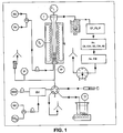
- the experimental tool used (cf. figure 1 ) is composed of a quartz reactor containing a fluidized bed of redox mass, a liquid injection system in the reactor and a flue gas analysis system.
- the reactor is quartz, its inner diameter is 2 cm.
- the reactor can be fluidized by different gases (air, nitrogen N2, CO2, H2O) and fed by different liquids.
- the liquids to be tested may be preheated to 180 ° C. in order to reduce their viscosity if necessary, and ensure their injection into the reactor.
- the redox mass (45 g) forms a bed of solid particles of NiO nickel oxides on NiAl2O4 support (in a proportion of 60% by weight / 40% by weight), with a particle size of between 100 and 300 ⁇ m, continuously fluidized.
- a reactor operating in batch mode with the fluidized redox mass (without circulation of the redox mass) is used.
- the metal oxides undergo several oxidation-reduction cycles. During the oxidation phase of the metal, the bed is fluidized with air. During the metal reduction phase, a defined quantity of liquid filler (2 mL) is injected punctually into the bed of solid particles, the bed being then fluidized with nitrogen.
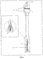
- the flow rate of fluidization gas in the reactor is distributed equitably in two zones (cf. figure 2 ): by the central tube (30 NL / h) and by the annular part (30 NL / h).
- a 6-way valve, a liquid feed tank B and a syringe S are used to occasionally inject the feed into the reactor.
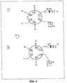
- the injection protocol is described on the figure 3 .
- the syringe S is first filled with the liquid charge (position 1 of the 6-way valve, filling of the syringe S).
- the valve is in position 1, the liquid contained in the syringe S being pushed towards the charging tank B; the bed is fluidized by the fluidizing gas Gf which is air (30 NL / h in the central tube and 30 NL / h in the annular part).
- the fluidizing gas Gf is air (30 NL / h in the central tube and 30 NL / h in the annular part).
- the fluidization air Gf is replaced by nitrogen.
- the valve is switched to position 2, during the injection time of the load (duration: two seconds).
- the liquid, pushed by the syringe, is then directed towards the reactor R by the central tube; the bed is fluidized with nitrogen (30 NL / h in the annular part). After the programmed duration of the injection, the valve switches back to position 1.
- the bed is then fluidized by the nitrogen passing through the central tube and the annular portion; the liquid charge pushed by the syringe being directed towards the load tank.
- the fumes are continuously analyzed by a NGA 2000 MLT4 multi gas analyzer (An. CO, CO2, O2, CH4, H2) for measurements in CO / CO2 / CH4 / O2 / H2.
- An FID Flume Ionization Detector: An. FID
- the two liquid feedstocks described above were tested: domestic fuel oil and No. 2 heavy fuel oil.
- the nickel oxide of the redox mass was previously completely oxidized.
- the temperature of the bed (T L ) during the injection of the different liquid charges is 900 ° C.
- the partial combustion by chemical loop can be carried out in a similar manner for the production of synthesis gas, for example by decreasing the amount of oxygen stored in the metal oxides.
Landscapes
- Chemical & Material Sciences (AREA)
- Chemical Kinetics & Catalysis (AREA)
- Organic Chemistry (AREA)
- Engineering & Computer Science (AREA)
- Combustion & Propulsion (AREA)
- Health & Medical Sciences (AREA)
- General Health & Medical Sciences (AREA)
- Inorganic Chemistry (AREA)
- Mechanical Engineering (AREA)
- General Engineering & Computer Science (AREA)
- Production Of Liquid Hydrocarbon Mixture For Refining Petroleum (AREA)
Description
- L'invention concerne la mise en contact de charges liquides lourdes avec des particules solides capables de céder de l'oxygène dans une zone réactionnelle de réduction. L'oxygène cédé par les particules permet de faire la combustion de la charge liquide. Les effluents de la zone de combustion contiennent essentiellement des oxydes gazeux résultant de la combustion, et de la vapeur d'eau. Les particules ayant participé à la combustion sont ensuite évacuées vers une zone réactionnelle d'oxydation où elles sont réoxydées par contact à l'air. La circulation en continu des particules oxydées entre les deux zones permet de faire en continu une combustion de la charge liquide en évitant tout contact direct entre la charge liquide et l'air. Ce procédé permet d'effectuer la combustion du combustible en l'absence d'azote et de produire des fumées concentrées en CO2 exemptes d'azote facilitant la séquestration du CO2.
- Nous avons découvert que les liquides de type sous-produits pétroliers peuvent être utilisés comme charges pour le procédé de combustion en boucle chimique, afin de les brûler soit totalement et produire du CO2 et de l'eau, soit partiellement et produire du gaz de synthèse composé de CO et H2.
- Ce procédé utilisant les charges liquides est particulièrement intéressant, car il permet de valoriser les sous-produits pétroliers afin de produire de la chaleur avec captage du CO2 émis, ou produire du gaz de synthèse.
- Procédé de Chemical Looping Combustion ou CLC : Dans la suite du texte, on entend par procédé CLC (Chemical Looping Combustion) un procédé d'oxydo-réduction en boucle sur masse active. Il convient de noter que, de manière générale, les termes oxydation et réduction sont utilisés en relation avec l'état respectivement oxydé ou réduit de la masse active. Le réacteur d'oxydation est celui dans lequel la masse oxydo-réductrice est oxydée et le réacteur de réduction est le réacteur dans lequel la masse oxydo-réductrice est réduite. Lors de la réduction de la masse oxydo-réductrice, le combustible peut être soit totalement oxydé, produisant du CO2 et H2O, soit partiellement oxydé, produisant du gaz de synthèse CO et H2.
- Une valorisation des coupes pétrolières lourdes, non distillables dans les conditions atmosphériques, est souvent recherchée.
Une manière connue de valoriser directement les coupes pétrolières non distillables dans les conditions atmosphériques (coupe 340°C+) est de les brûler pour produire de l'énergie. La combustion de ce type de combustibles soulève néanmoins la problématique du captage du CO2 émis dans les fumées, préjudiciable à l'environnement. - Le procédé CLC (Chemical Looping Combustion) ou procédé d'oxydo-réduction en boucle sur masse active consiste à mettre en oeuvre des réactions d'oxydo-réduction d'une masse active pour décomposer la réaction de combustion en deux réactions successives. Une première réaction d'oxydation de la masse active avec de l'air ou un gaz jouant le rôle de comburant, permet, du fait du caractère exothermique de l'oxydation, d'obtenir un gaz chaud dont l'énergie peut ensuite être exploitée. Une seconde réaction de réduction de la masse active ainsi oxydée à l'aide d'un composé réducteur permet ensuite d'obtenir une masse active réutilisable ainsi qu'un mélange gazeux comprenant essentiellement du dioxyde de carbone et de l'eau. Cette technique permet donc d'isoler le dioxyde de carbone dans un mélange gazeux pratiquement dépourvu d'oxygène et d'azote.
- Le brevet
US 5,447,024 décrit un procédé CLC comprenant un premier réacteur de réduction d'une masse active à l'aide d'un gaz réducteur et un second réacteur d'oxydation permettant de restaurer la masse active dans son état oxydé par une réaction d'oxydation avec de l'air humidifié. La technologie du lit fluidisé circulant est utilisée pour permettre le passage continu de la masse active de son état oxydé à son état réduit.
La masse active passant alternativement de sa forme oxydée à sa forme réduite et inversement, décrit un cycle d'oxydo-réduction. Il convient de noter que, de manière générale, les termes oxydation et réduction sont utilisés en relation avec l'état respectivement oxydé ou réduit de la masse active. Le réacteur d'oxydation est celui dans lequel la masse oxydo-réductrice est oxydée et le réacteur de réduction est le réacteur dans lequel la masse oxydo-réductrice est réduite. - Ainsi, dans le réacteur de réduction, la masse active (MxOy) est tout d'abord réduite à l'état MxOy-2n-m/2, par l'intermédiaire d'un hydrocarbure CnHm, qui est corrélativement oxydé en CO2 et H2O, selon la réaction (1), ou éventuellement en mélange CO + H2 selon les proportions utilisées.

- Dans le réacteur d'oxydation, la masse active est restaurée à son état oxydé (MxOy) au contact de l'air selon la réaction (2), avant de retourner vers le premier réacteur.

- L'efficacité du procédé CLC en lit fluidisé circulant repose dans une large mesure sur les propriétés physico-chimiques de la masse active d'oxydo-réduction. La réactivité du ou des couples oxydo-réducteurs mis en jeu ainsi que la capacité de transfert d'oxygène associée sont des paramètres qui influent sur le dimensionnement des réacteurs et sur les vitesses de circulation des particules. La durée de vie des particules quant à elle dépend de la résistance mécanique des particules ainsi que de leur stabilité chimique. Afin d'obtenir des particules utilisables pour ce procédé, les particules mises en jeu sont généralement composées d'un couple ou d'un ensemble de couples oxydo-réducteurs choisi parmi CuO/Cu, Cu2O/Cu, NiO/Ni, Fe2O3/Fe3O4, FeO/Fe, Fe3O4/FeO, MnO2/Mn2O3, Mn3O3/Mn3O4, Mn3O4/MnO, MnO/Mn, Co3O4/CoO, CoO/Co, et d'un liant apportant la stabilité physico-chimique nécessaire.
- De nombreuses études avec des charges gaz (essentiellement méthane) et des charges solides ont été menées et ont montré la faisabilité de la boucle chimique de combustion pour ce type de charges.
Pour les charges gaz, une chimie réactive directe a lieu entre les particules solides oxydées et le combustible. Pour les charges solides, il faut d'abord les gazéifier (en gaz de synthèse CO et H2) pour permettre leur conversion au contact de la masse oxydo-réductrice. La gazéification représente donc l'étape limitante temporellement. Aussi, pour augmenter le temps de résidence de la charge solide, la fraction non convertie issue du réacteur de réduction est séparée de la masse oxydo-réductrice (par différence de densité entre la charge solide et la masse oxydo-réductrice via un séparateur solide/solide - brevet2 896 709 - La demande de brevet
WO 2008/036902 A2 décrit le procédé CLC appliqué de manière générale à diverses charges: gazeuses, liquides et solides. L'utilisation des charges liquides lourdes, produits du raffinage qui ont la particularité de ne pas être distillables dans les conditions atmosphériques, n'est pas envisagée. - L'utilisation de combustibles liquides génère des difficultés supplémentaires de mise en oeuvre que l'on ne rencontre pas pour les charges gazeuses ou solides, à savoir la vaporisation de la charge au contact des masses oxydo-réductrices ainsi que la formation de coke autour des particules oxydo-réductrices. Contrairement aux charges solides, il n'est pas envisageable de séparer les imbrûlés (coke déposé sur la masse oxydo-réductrice) de la masse oxydo-réductrice pour un recycle dans le réacteur de réduction (différences de densité et de taille de particules trop faibles). Le temps de séjour de la charge liquide dans ce réacteur est avantageusement rigoureusement contrôlé pour garantir l'oxydation de la charge vaporisée ainsi que la gazéification du coke formé et son oxydation, ceci afin d'obtenir le niveau d'oxydation désiré en une passe.
Nous avons découvert que la combustion de charges liquides lourdes pouvait se faire dans un procédé de type Chemical Looping Combustion, par mise en contact de la charge liquide avec une masse oxydo-réductrice en lit fluidisé, afin de valoriser les fractions pétrolières liquides lourdes du raffinage, tout en évitant la problématique des fumées riches en CO2. - L'objet de l'invention est d'utiliser le procédé de boucle chimique de combustion pour valoriser des charges liquides lourdes, soit afin de produire de l'énergie en oxydant totalement les charges liquides lourdes, tout en permettant le captage direct du CO2 émis dans les fumées de combustion, soit afin de produire un gaz de synthèse (composé d'hydrogène et de monoxyde de carbone).
- L'invention consiste à mettre en contact une charge liquide lourde, c'est-à-dire ayant moins de 10% en volume de ses composants dont le point d'ébullition en conditions atmosphériques est inférieur à 340°C, avec une masse oxydo-réductrice en lit fluidisé afin d'en effectuer la combustion dans un procédé de type Chemical Looping.
- L'invention concerne un procédé tel que divulgué dans la présente revendication 1. Les modes de réalisation préférés sont présentés dans les revendications dépendantes. De préférence, la charge liquide comprend un résidu de distillation sous vide. Avantageusement, la charge liquide est atomisée au sein du lit fluidisé.
- De préférence, la température du lit fluidisé est comprise entre 700°C et 1200°C.
- Dans un mode de réalisation, on effectue une combustion partielle de la charge.
- Dans ce cas, on produit du gaz de synthèse.
- Le gaz permettant la fluidisation peut comprendre de la vapeur d'eau, et le procédé permet de produire un mélange gazeux CO 2 + H2.
- Dans un autre mode de réalisation, on effectue une combustion totale de la charge.
- Dans ce cas, le procédé permet à la fois la production d'énergie et la captation du CO2 émis.
- La mise en oeuvre du procédé de Chemical Looping est faite à l'aide d'un lit fluidisé circulant, utilisant deux réacteurs interconnectés. Dans le premier, réacteur d'oxydation, la masse oxydo-réductrice s'oxyde au contact de l'air. Après séparation de la masse oxydée et de l'air appauvri en oxygène, la masse oxydo-réductrice est injectée dans le second réacteur, la chambre de combustion ou réacteur de réduction. Le combustible injecté y consomme l'oxygène du porteur (réduction de la masse oxydo-réductrice) pour s'oxyder en un mélange principalement composé de CO2 et d'eau, facilement séparables. La masse réduite est ensuite réinjectée dans le premier réacteur pour suivre un nouveau cycle.
- La mise en oeuvre de ce procédé se fait par un lit fluidisé circulant.
- Le temps de réaction est compris entre 10 secondes et 10 minutes, préférentiellement entre 1 minute et 5 minutes.
- Il est possible de fluidiser la masse oxydo-réductrice avec de la vapeur d'eau, et/ou du CO2 et/ou des composés soufrés SOx comme gaz de fluidisation.
- La température de la masse oxydo-réductrice (température du lit) lors de la mise en contact est comprise entre 700 et 1200°C, préférentiellement entre 800 et 1000°C.
- En fonction de l'utilisation des gaz de combustion, la pression du procédé sera ajustée. Ainsi, pour effectuer une combustion totale, on aura intérêt à travailler à pression faible pour minimiser le coût énergétique de compression des gaz et maximiser ainsi le rendement énergétique de l'installation. Pour produire du gaz de synthèse, on pourra avantageusement dans certains cas travailler en pression, afin d'éviter la compression du gaz de synthèse en amont du procédé de synthèse aval: le procédé Fischer Tropsch travaillant par exemple à des pressions comprises entre 20 et 40 bars, on pourra trouver un intérêt à produire le gaz à une pression plus élevée.
- La capacité de stockage en oxygène de la masse oxydo-réductrice est avantageusement comprise, suivant le type de matériau, entre 4 et 30 % poids. La masse oxydo-réductrice peut être composée d'oxydes métalliques seuls ou en mélange, avec ou sans liant, d'oxydes métalliques-cérine/zircone, de spinelles, de minerai (tel que l'ilménite), de pérovskites, ou toute autre masse ayant les propriétés d'oxydo-réduction requises et les caractéristiques nécessaires à la mise en oeuvre de la fluidisation.
- Le taux d'utilisation de l'oxygène disponible varie généralement entre 2 et 50% poids, préférentiellement entre 5 et 20 % poids.
- La charge liquide est injectée dans le lit dense du réacteur de réduction. Elle est préférentiellement atomisée au sein du lit fluidisé pour former des gouttelettes de taille proche de la taille des particules, ceci afin d'optimiser le contact liquide-solide. En effet, une partie de la charge liquide se vaporise au contact de la masse oxydo-réductrice chaude, l'autre partie se condense pour former un dépôt de coke à la surface de la masse oxydo-réductrice.
- La charge liquide peut être préchauffée, notamment pour diminuer sa viscosité.
- Le temps de séjour de la masse oxydo-réductrice est avantageusement au moins égal au temps de réaction de la charge liquide. Le temps de séjour de la masse oxydo-réductrice est compris entre 10 secondes et 10 minutes, préférentiellement entre 1 minute et 5 minutes.
- Le rapport entre le débit massique de masse oxydo-réductrice sur le débit massique de charge est avantageusement compris entre 20 et 1000, préférentiellement entre 50 et 400.
- Les charges liquides pouvant être utilisées dans ce procédé de boucle chimique de combustion en lit fluidisé concernent toute fraction hydrocarbonée liquide provenant de la production ou du raffinage de pétrole dont le point d'ébullition dans les conditions atmosphériques est majoritairement supérieur à 340°C (c'est-à-dire toute coupe dont la courbe de distillation fait apparaître que moins de 10% en volume de ses composants bout à une température inférieure à 340°C).
- Les charges concernées sont notamment les coupes de type résidus atmosphériques (résidus de distillation menée dans les conditions atmosphériques); ou de préférence les coupes de type résidus sous vide (résidus de distillation menée sous vide) pour lesquelles moins de 10% en volume des composants a un point d'ébullition inférieur à 500°C; ou enfin les résidus de procédés de désasphaltage constitués du précipité obtenu après contact avec un solvant paraffinique constitué d'un alcane dont le nombre d'atomes de carbone est compris entre 3 et 7.
- La charge contient donc majoritairement des fractions lourdes difficilement convertibles et non intégrables dans les bases carburant, seules ou en mélange, telles que les fuels de soute, les résidus de distillation atmosphériques ou de distillation sous vide, les résidus de procédé de conversion (hydroconversion en lit bouillonnant, FCC...), les asphaltes issus des procédés de désasphaltage, notamment désasphaltage au propane, butane, pentane, hexane, heptane, ou des bitumes (par exemple fractions de bruts lourds du Canada non distillables).
- Le pourcentage de résidu solide résultant de la vaporisation et de la pyrolyse d'un produit pétrolier est défini par son carbone Conradson. Le procédé selon l'invention permet de valoriser des charges lourdes ayant un carbone Conradson allant jusqu'à 40%.
- De même, le procédé selon l'invention est avantageusement applicable à des charges lourdes ayant une teneur en asphaltènes précipitant dans l'heptane allant jusqu'à 25%.
- Si l'oxydation de la charge liquide est complète, le procédé selon l'invention permet d'obtenir des fumées fortement concentrées en CO2 (pouvant être comprimé, transporté et stocké). Le procédé selon l'invention peut donc être utilisé pour la captation du CO2.
- Si l'oxydation de la charge liquide est partielle, le procédé selon l'invention permet de produire du gaz de synthèse (CO et H2).
- Dans le cas de la combustion partielle, le ratio masse active/combustible est généralement ajusté de manière à réaliser l'oxydation partielle du combustible, produisant un gaz de synthèse sous forme d'un mélange CO + H2.
- Afin de n'obtenir qu'une oxydation partielle de la charge, on peut également, par rapport aux conditions nécessaires à l'obtention d'une combustion totale par Chemical Looping Combustion:
- diminuer le temps de séjour des particules dans le réacteur d'oxydation (pour ne pas oxyder totalement les particules),
- utiliser une masse oxydo-réductrice ayant une capacité de stockage d'oxygène plus faible,
- diminuer le débit de circulation des oxydes métalliques dans le réacteur d'oxydation
- augmenter le débit de la charge dans le réacteur de réduction.
- Ce gaz de synthèse peut être utilisé comme charge d'autres procédés de transformation chimique, par exemple le procédé Fischer Tropsch permettant de produire à partir de gaz de synthèse des hydrocarbures liquides à chaînes hydrocarbonées longues utilisables ensuite comme bases carburants.
- Dans le cas où le gaz de fluidisation utilisé est la vapeur d'eau ou un mélange de vapeur d'eau et d'autre(s) gaz, la réaction du gaz CO à l'eau (ou water gas shift en termes anglo-saxons,

- Dans ce cas, le gaz de combustion peut être utilisé à des fins de production d'énergie compte tenu de son pouvoir calorifique.
- On peut également envisager d'utiliser ce gaz pour la production d'hydrogène, pour par exemple alimenter des unités d'hydrogénation, d'hydrotraitement en raffinage ou un réseau de distribution d'hydrogène (après réaction de water gaz shift).
- Dans le cas de la combustion totale, le flux de gaz en sortie du réacteur de réduction est composé essentiellement de CO2 et de vapeur d'eau. Un flux de CO2 prêt à être séquestré est ensuite obtenu par condensation de la vapeur d'eau. Le procédé peut ainsi être utilisé pour la production d'énergie, tout en permettant la captation du CO2 contenu dans les fumées.
- Les
figures 1 à 4 illustrent l'invention sans en limiter la portée. -
Figure 1 : Schéma de l'installation expérimentale utilisée dans l'exemple. Les sigles suivants concernent :- Cd : condenseur
- Gf : groupe froid
- Ft : filtre
- An. : analyseur
- FID : Flame Ionization Detector
- GV : générateur de vapeur
- T° : mesure de température
- TL: mesure de température du lit
- TF: mesure de température du four
- P : mesure de pression.
-
Figure 2 : Schéma du réacteur utilisé dans l'exemple et détail de la partie permettant l'injection, composée d'un tube central (tc) et d'une partie annulaire (pa).- an. : analyseur
- F : fritté
- Pt : puits pour thermocouples
-
Figure 3 : Schéma du système d'injection utilisant une vanne 6-voies utilisé dans l'exemple, où chacune des voies porte un numéro 1 à 6. L'injection se fait depuis un bac de charge B à l'aide d'une seringue S. La vanne 6 voies permet d'alterner l'injection de charge avec celle du gaz de fluidisation Gf dans le réacteur R, le gaz de fluidisation étant envoyé à l'évent E pendant l'injection de la charge. -
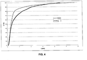
Figure 4 : Graphique montrant le carbone émis en % C sous la forme de CO2 en fonction du temps t en minutes pour les charges fuel domestique FOD et fuel lourd FL n°2 injectées ponctuellement à t = 0, sur NiO/NiAl2O4 à 900°C (exemple). -
Figure 5 : Courbe de distillation simulée (DS421) du fuel lourd n°2 de l'exemple (fraction volumique en fonction de la température T en °C). - L'exemple ci-dessous illustre l'invention à titre non limitatif.
- La combustion totale par boucle chimique de différentes charges liquides (fuel domestique : charge non conforme à l'invention et fuel lourd n°2 : charge conforme à l'invention) a été mise en évidence.
- Le fuel lourd n°2 a les caractéristiques suivantes :
- densité à 15°C = 0.9858
- viscosité cinématique= 38 mm2/s à 100°C
- viscosité cinématique= 522 mm2/s à 50°C
- Teneur en soufre S=1.3%pds
- Teneur en hydrogène H=10.8%pds
- A titre comparatif, le fuel domestique a une densité à 15°C de 0.8562, une teneur en soufre de 0.1% pds et une teneur en hydrogène H=12.4% pds. Par ailleurs, la fraction de fuel domestique ayant un point d'ébullition inférieur à 340°C représente 87% en volume.
- L'outil expérimental utilisé (cf.
figure 1 ) est composé d'un réacteur en quartz contenant un lit fluidisé de masse oxydo-réductrice, un système d'injection liquide dans le réacteur et un système d'analyse des fumées. Le réacteur est en quartz, son diamètre intérieur est de 2 cm. Le réacteur peut être fluidisé par différents gaz (air, azote N2, CO2, H20) et alimenté par différents liquides. Les liquides à tester peuvent être préalablement chauffés jusqu'à 180°C afin de diminuer leur viscosité si besoin, et assurer leur injection dans le réacteur. La masse oxydo-réductrice (45g) forme un lit de particules solides d'oxydes de nickel NiO sur support NiAl2O4 (en proportion 60%poids/40%poids), de granulométrie comprise entre 100 et 300 µm, fluidisé en permanence. Afin d'obtenir une simulation du procédé de Chemical Looping Combustion, on utilise un réacteur opérant en batch avec la masse oxydo-réductrice fluidisée (sans circulation de la masse oxydo-réductrice). - Les oxydes métalliques subissent plusieurs cycles d'oxydation-réduction. Lors de la phase d'oxydation du métal, le lit est fluidisé à l'air. Lors de la phase de réduction du métal, une quantité définie de charge liquide (2 mL) est injectée ponctuellement dans le lit de particules solides, le lit étant alors fluidisé par de l'azote. Le débit de gaz de fluidisation dans le réacteur est réparti équitablement en deux zones (cf.
figure 2 ) : par le tube central (30 NL/h) et par la partie annulaire (30 NL/h).
Une vanne 6-voies, un bac de charge liquide B et une seringue S sont utilisés afin d'injecter ponctuellement la charge dans le réacteur. Le protocole d'injection est décrit sur lafigure 3 . La seringue S est au préalable remplie par la charge liquide (position 1 de la vanne 6-voies, remplissage de la seringue S). Lors de la phase d'oxydation de la masse oxydo-réductrice, la vanne est en position 1, le liquide contenu dans la seringue S étant poussé vers le bac de charge B; le lit est fluidisé par le gaz de fluidisation Gf qui est de l'air (30 NL/h dans le tube centrale et 30 NL/h dans la partie annulaire).
Une fois le métal totalement oxydé (l'oxygène de l'air étant totalement restitué à la sortie du réacteur), l'air de fluidisation Gf est remplacé par de l'azote. Lors de la phase de réduction de la masse oxydo-réductrice, la vanne est basculée en position 2, durant le temps d'injection de la charge (durée : deux secondes). Le liquide, poussé par la seringue, est alors orienté vers le réacteur R par le tube central; le lit est fluidisé par l'azote (30 NL/h dans la partie annulaire). Après la durée programmée de l'injection, la vanne bascule à nouveau en position 1. Le lit est alors fluidisé par l'azote passant dans le tube central et la partie annulaire; la charge liquide poussée par la seringue étant orientée vers le bac de charge. Les fumées sont analysées en continu par un Analyseur multi gaz NGA 2000 MLT4 (An. CO, CO2, O2, CH4, H2) pour mesures en CO / CO2 / CH4 / O2 / H2. Un appareillage de type FID (Flame Ionization Detector : An. FID) permet également la mesure de la concentration en carbone total. - Les deux charges liquides décrites ci-dessus ont été testées : du fuel domestique et du fuel lourd n° 2. L'oxyde de nickel de la masse oxydo-réductrice est au préalable totalement oxydé. La température du lit (TL) lors de l'injection des différentes charges liquides est de 900°C. La
figure 4 montre le pourcentage de carbone émis dans les fumées sous forme de CO2 en fonction du temps; deux mL de charge liquide étant injectés en deux secondes à t = 0. On observe que la quasi totalité du carbone contenu dans les deux charges liquides testées (>99%w) est convertie en CO2. La réaction de réduction de l'oxyde de nickel étant endothermique, une baisse de température du lit d'environ 30°C est observée avec les deux charges. Lors de la ré-oxydation du métal, une quantité limitée de CO2 est émise (< 1% poids du carbone contenu dans la charge injectée), ce qui montre qu'il n'y a pas ou très peu de coke résiduel sur la masse oxydo-réductrice. L'exothermicité observée lors de l'oxydation du métal génère une augmentation de la température du lit d'environ 30°C. Ces expériences montrent la faisabilité du procédé de boucle chimique de combustion appliqué aux charges liquides lourdes (comme le fuel lourd n°2 testé), et notamment aux résidus pétroliers. - Avec l'outil expérimental décrit dans l'exemple, la combustion partielle par boucle chimique peut être effectuée de manière similaire pour la production de gaz de synthèse, par exemple en diminuant la quantité d'oxygène stocké dans les oxydes métalliques.
- Cette expérience montre qu'en jouant sur la quantité d'oxygène disponible stockée dans les oxydes métalliques, le procédé CLC peut être utilisé soit pour la production d'énergie tout en captant le CO2 émis dans les fumées (combustion totale, degré d'oxydation du métal élevé), soit pour la production de gaz de synthèse (combustion partielle, degré d'oxydation du métal faible).
La courbe de distillation simulée (DS421) du fuel lourd n°2 (charge conforme à l'invention) est donnée à la
Claims (10)
- Procédé de valorisation d'une charge liquide composée de fractions hydrocarbonées, seules ou en mélange, dont moins de 10 % en volume a un point d'ébullition inférieur à 340°C par combustion en boucle chimique d'oxydoréduction en lit fluidisé, dans lequel :a) on oxyde une masse oxydo-réductrice au contact de l'air dans un réacteur d'oxydation;b) on sépare la masse oxydée de l'air appauvri en oxygène;c) on réduit la masse oxydée dans un réacteur de réduction ou combustion et on oxyde la charge liquide pour former un mélange principalement composé de CO2 et d'eau;d) on réinjecte la masse réduite dans le réacteur d'oxydation de l'étape a) pour commencer un nouveau cycle.le temps de séjour de la masse oxydo-réductrice dans le réacteur de combustion étant compris entre 10 secondes et 10 minutes.
- Procédé de valorisation d'une charge liquide selon la revendication 1 dans lequel le temps de séjour est compris entre 1 et 5 minutes.
- Procédé de valorisation d'une charge liquide selon la revendication 1 ou 2 dans lequel la charge liquide comprend un résidu de distillation sous vide.
- Procédé de valorisation d'une charge liquide selon la revendication 1 à 3 dans lequel la charge liquide est atomisée au sein du lit fluidisé.
- Procédé de valorisation d'une charge liquide selon l'une des revendications précédentes dans lequel la température du lit fluidisé est comprise entre 700°C et 1200°C.
- Procédé de valorisation d'une charge liquide selon l'une des revendications précédentes par combustion partielle de la charge.
- Procédé de valorisation d'une charge liquide selon la revendication 6 dans lequel on produit du gaz de synthèse.
- Procédé de valorisation d'une charge liquide selon la revendication 6 dans lequel le gaz permettant la fluidisation comprend de la vapeur d'eau et dans lequel on produit, après réaction du gaz CO à l'eau, un mélange gazeux CO2 + H2 en sortie de réacteur.
- Procédé de valorisation d'une charge liquide selon l'une des revendications 1 à 5 par combustion totale de la charge.
- Procédé de valorisation d'une charge liquide selon la revendication 9 par production d'énergie et captation du CO2 émis.
Priority Applications (1)
| Application Number | Priority Date | Filing Date | Title |
|---|---|---|---|
| PL09745907T PL2274233T3 (pl) | 2008-04-30 | 2009-04-28 | Sposób spalania w pętli chemicznej ciężkich ciekłych frakcji węglowodorowych |
Applications Claiming Priority (2)
| Application Number | Priority Date | Filing Date | Title |
|---|---|---|---|
| FR0802450A FR2930771B1 (fr) | 2008-04-30 | 2008-04-30 | Procede de combustion en boucle chimique de fractions hydrocarbonees liquides lourdes. |
| PCT/FR2009/000498 WO2009138588A1 (fr) | 2008-04-30 | 2009-04-28 | Procédé de combustion en boucle chimique de fractions hydrocarbonées liquides lourdes |
Publications (2)
| Publication Number | Publication Date |
|---|---|
| EP2274233A1 EP2274233A1 (fr) | 2011-01-19 |
| EP2274233B1 true EP2274233B1 (fr) | 2018-09-19 |
Family
ID=40076670
Family Applications (1)
| Application Number | Title | Priority Date | Filing Date |
|---|---|---|---|
| EP09745907.7A Active EP2274233B1 (fr) | 2008-04-30 | 2009-04-28 | Procédé de combustion en boucle chimique de fractions hydrocarbonées liquides lourdes |
Country Status (7)
| Country | Link |
|---|---|
| US (1) | US9297528B2 (fr) |
| EP (1) | EP2274233B1 (fr) |
| CA (1) | CA2721839C (fr) |
| ES (1) | ES2702448T3 (fr) |
| FR (1) | FR2930771B1 (fr) |
| PL (1) | PL2274233T3 (fr) |
| WO (1) | WO2009138588A1 (fr) |
Families Citing this family (9)
| Publication number | Priority date | Publication date | Assignee | Title |
|---|---|---|---|---|
| FR2936301B1 (fr) * | 2008-09-23 | 2010-09-10 | Inst Francais Du Petrole | Procede et dispositif optimises de combustion par boucle chimique sur des charges hydrocarbonees liquides |
| FR2937648B1 (fr) * | 2008-10-24 | 2010-11-19 | Inst Francais Du Petrole | Enchainement integre de procedes d'extraction et de traitement d'un brut extra lourd ou bitumeux avec captage de co2 |
| US9352270B2 (en) | 2011-04-11 | 2016-05-31 | ADA-ES, Inc. | Fluidized bed and method and system for gas component capture |
| IN2015DN02082A (fr) | 2012-09-20 | 2015-08-14 | Ada Es Inc | |
| FR2997318A1 (fr) * | 2012-10-31 | 2014-05-02 | IFP Energies Nouvelles | Procede de combustion en boucle chimique utilisant une masse oxydo-reductrice comprenant de la pyrolusite enrichie avec de l'oxyde de nickel |
| US9909756B2 (en) | 2012-11-30 | 2018-03-06 | Saudi Arabian Oil Company | Staged chemical looping process with integrated oxygen generation |
| FR3001399A3 (fr) * | 2013-01-29 | 2014-08-01 | IFP Energies Nouvelles | Masse active d'oxydo-reduction comprenant de la pyrolusite enrichie en nickel et un compose a structure spinelle et utilisation dans un procede de combustion en boucle chimique |
| FR3004126B1 (fr) * | 2013-04-05 | 2016-01-01 | IFP Energies Nouvelles | Procede et dispositif de combustion par boucle chimique de charges hydrocarbonees liquides |
| FR3166687A1 (fr) | 2024-09-20 | 2026-03-27 | IFP Energies Nouvelles | Procede de combustion en boucle chimique d'un combustible comprenant une forte teneur en volatiles |
Family Cites Families (20)
| Publication number | Priority date | Publication date | Assignee | Title |
|---|---|---|---|---|
| US2106013A (en) * | 1937-03-08 | 1938-01-18 | Ernest A Ocon | Process for refining and cracking oil |
| JPS49131201A (fr) * | 1973-04-24 | 1974-12-16 | ||
| US4542114A (en) * | 1982-08-03 | 1985-09-17 | Air Products And Chemicals, Inc. | Process for the recovery and recycle of effluent gas from the regeneration of particulate matter with oxygen and carbon dioxide |
| US4724068A (en) * | 1986-07-17 | 1988-02-09 | Phillips Petroleum Company | Hydrofining of oils |
| IT1244427B (it) * | 1990-07-05 | 1994-07-15 | Eduardo Luigi Szego | Processo di combustione di idrocarburi in cui si evita la dispersione in atmosfera dell'anidride carbonica prodotta, ed impianto atto a realizzarlo |
| JP3315719B2 (ja) * | 1992-06-03 | 2002-08-19 | 東京電力株式会社 | 化学ループ燃焼方式発電プラントシステム |
| US5827496A (en) * | 1992-12-11 | 1998-10-27 | Energy And Environmental Research Corp. | Methods and systems for heat transfer by unmixed combustion |
| US6007699A (en) * | 1996-08-21 | 1999-12-28 | Energy And Environmental Research Corporation | Autothermal methods and systems for fuels conversion |
| US5906806A (en) * | 1996-10-16 | 1999-05-25 | Clark; Steve L. | Reduced emission combustion process with resource conservation and recovery options "ZEROS" zero-emission energy recycling oxidation system |
| US6143203A (en) * | 1999-04-13 | 2000-11-07 | The Boc Group, Inc. | Hydrocarbon partial oxidation process |
| CN1179022C (zh) * | 2001-05-30 | 2004-12-08 | 中国石油化工股份有限公司 | 伴有催化剂低温再生的轻质石油烃催化改质方法 |
| US6878362B2 (en) * | 2002-04-05 | 2005-04-12 | General Electric Company | Fuel processor apparatus and method based on autothermal cyclic reforming |
| US7767191B2 (en) * | 2003-12-11 | 2010-08-03 | The Ohio State University | Combustion looping using composite oxygen carriers |
| US7540893B2 (en) * | 2005-12-06 | 2009-06-02 | General Electric Company | System and method for producing synthesis gas |
| CA2636325C (fr) * | 2006-01-12 | 2015-04-28 | The Ohio State University | Systemes et procedes de conversion de combustible |
| US7824574B2 (en) * | 2006-09-21 | 2010-11-02 | Eltron Research & Development | Cyclic catalytic upgrading of chemical species using metal oxide materials |
| US7780749B2 (en) * | 2006-12-11 | 2010-08-24 | General Electric Company | Unmixed fuel processors and methods for using the same |
| US7700005B2 (en) * | 2006-12-26 | 2010-04-20 | Saudi Arabian Oil Company | Oil-based thermo-neutral reforming with a multi-component catalyst |
| US20110094226A1 (en) * | 2009-10-28 | 2011-04-28 | Mchugh Lawrence F | Process and apparatus for high energy efficiency chemical looping combustion |
| US8356992B2 (en) * | 2009-11-30 | 2013-01-22 | Chevron U.S.A. Inc. | Method and system for capturing carbon dioxide in an oxyfiring process where oxygen is supplied by regenerable metal oxide sorbents |
-
2008
- 2008-04-30 FR FR0802450A patent/FR2930771B1/fr active Active
-
2009
- 2009-04-28 EP EP09745907.7A patent/EP2274233B1/fr active Active
- 2009-04-28 PL PL09745907T patent/PL2274233T3/pl unknown
- 2009-04-28 CA CA2721839A patent/CA2721839C/fr active Active
- 2009-04-28 WO PCT/FR2009/000498 patent/WO2009138588A1/fr not_active Ceased
- 2009-04-28 US US12/990,395 patent/US9297528B2/en active Active
- 2009-04-28 ES ES09745907T patent/ES2702448T3/es active Active
Non-Patent Citations (1)
| Title |
|---|
| None * |
Also Published As
| Publication number | Publication date |
|---|---|
| WO2009138588A1 (fr) | 2009-11-19 |
| ES2702448T3 (es) | 2019-03-01 |
| CA2721839C (fr) | 2015-04-21 |
| PL2274233T3 (pl) | 2019-06-28 |
| US20110097673A1 (en) | 2011-04-28 |
| CA2721839A1 (fr) | 2009-11-19 |
| US9297528B2 (en) | 2016-03-29 |
| EP2274233A1 (fr) | 2011-01-19 |
| FR2930771A1 (fr) | 2009-11-06 |
| FR2930771B1 (fr) | 2011-07-22 |
Similar Documents
| Publication | Publication Date | Title |
|---|---|---|
| CA2721839C (fr) | Procede de combustion en boucle chimique de fractions hydrocarbonees liquides lourdes | |
| EP2802638B1 (fr) | Procédé integre de gazeification et combustion indirecte de charges hydrocarbonees solides en boucle chimique | |
| EP2391695B1 (fr) | Procède intégré d'oxydation, réduction et gazéification pour production de gaz de synthèse et d'énergie en boucle chimique | |
| CA2907810C (fr) | Procede et dispositif de combustion par boucle chimique de charges hydrocarbonees liquides | |
| FR2930733A1 (fr) | Masse active d'oxydo-reduction et procede de combustion en boucle chimique. | |
| FR2559497A1 (fr) | Procede de conversion de residus petroliers lourds en hydrogene et hydrocarbures gazeux et distillables | |
| EP2658950B1 (fr) | Procede de craquage catalytique pour le traitement d'une coupe a faible carbone conradson. | |
| CA2850612A1 (fr) | Procede de combustion en boucle chimique avec elimination des cendres et fines en sortie de la zone d'oxydation et installation utilisant un tel procede | |
| EP3230414A1 (fr) | Procede et installation de combustion par oxydo-réduction en boucle chimique d'une charge hydrocarbonee gazeuse avec vaporéformage catalytique intermediaire de la charge | |
| EP3390585B1 (fr) | Procédé de gazéification à lit fluidisé de pneus | |
| CA2739772C (fr) | Enchainement integre de procedes d'extraction et de traitement d'un brut extra lourd ou bitumeux avec captage de co2 | |
| EP3230415B1 (fr) | Procédé et installation de combustion par oxydo-réduction en boucle chimique d'une charge hydrocarbonée gazeuse avec reformage catalytique in situ de la charge | |
| WO2014068205A1 (fr) | Procédé de combustion en boucle chimique utilisant une masse oxydo-reductrice comprenant de la pyrolusite enrichie avec de l'oxyde de nickel | |
| WO2011131867A2 (fr) | Procédé intégré de traitement et de gazéification de charges bitumineuses en combustion en boucle chimique | |
| EP2551587A2 (fr) | Procédé de combustion en boucle chimique utilisant la pyrolusite comme masse oxydo-reductrice | |
| WO2021136912A1 (fr) | Procede integre de conversion thermique d'une charge hydrocarbonee lourde et de combustion indirecte en boucle chimique d'oxydo-reduction pour la production de flux hydrocarbones et le captage du co2 produit | |
| FR2995600A1 (fr) | Procede de reduction du dioxyde de carbone en monoxyde de carbone par des oxydes de vanadium | |
| CA2861050A1 (fr) | Procede integre de gazeification et combustion indirecte de charges hydrocarbonees solides en boucle chimique | |
| FR3166687A1 (fr) | Procede de combustion en boucle chimique d'un combustible comprenant une forte teneur en volatiles |
Legal Events
| Date | Code | Title | Description |
|---|---|---|---|
| PUAI | Public reference made under article 153(3) epc to a published international application that has entered the european phase |
Free format text: ORIGINAL CODE: 0009012 |
|
| 17P | Request for examination filed |
Effective date: 20101130 |
|
| AK | Designated contracting states |
Kind code of ref document: A1 Designated state(s): AT BE BG CH CY CZ DE DK EE ES FI FR GB GR HR HU IE IS IT LI LT LU LV MC MK MT NL NO PL PT RO SE SI SK TR |
|
| AX | Request for extension of the european patent |
Extension state: AL BA RS |
|
| DAX | Request for extension of the european patent (deleted) | ||
| RAP1 | Party data changed (applicant data changed or rights of an application transferred) |
Owner name: TOTAL RAFFINAGE CHIMIE Owner name: IFP ENERGIES NOUVELLES |
|
| 17Q | First examination report despatched |
Effective date: 20160518 |
|
| RAP1 | Party data changed (applicant data changed or rights of an application transferred) |
Owner name: IFP ENERGIES NOUVELLES Owner name: TOTAL RAFFINAGE CHIMIE |
|
| REG | Reference to a national code |
Ref country code: DE Ref legal event code: R079 Ref document number: 602009054602 Country of ref document: DE Free format text: PREVIOUS MAIN CLASS: C01B0003120000 Ipc: B01J0008220000 |
|
| GRAP | Despatch of communication of intention to grant a patent |
Free format text: ORIGINAL CODE: EPIDOSNIGR1 |
|
| STAA | Information on the status of an ep patent application or granted ep patent |
Free format text: STATUS: GRANT OF PATENT IS INTENDED |
|
| RIC1 | Information provided on ipc code assigned before grant |
Ipc: C01B 3/38 20060101ALI20180315BHEP Ipc: C01B 3/44 20060101ALI20180315BHEP Ipc: C01B 3/48 20060101ALI20180315BHEP Ipc: B01J 8/22 20060101AFI20180315BHEP Ipc: F23C 10/00 20060101ALI20180315BHEP Ipc: C01B 3/34 20060101ALI20180315BHEP Ipc: B01J 19/00 20060101ALI20180315BHEP |
|
| INTG | Intention to grant announced |
Effective date: 20180418 |
|
| GRAS | Grant fee paid |
Free format text: ORIGINAL CODE: EPIDOSNIGR3 |
|
| GRAA | (expected) grant |
Free format text: ORIGINAL CODE: 0009210 |
|
| STAA | Information on the status of an ep patent application or granted ep patent |
Free format text: STATUS: THE PATENT HAS BEEN GRANTED |
|
| AK | Designated contracting states |
Kind code of ref document: B1 Designated state(s): AT BE BG CH CY CZ DE DK EE ES FI FR GB GR HR HU IE IS IT LI LT LU LV MC MK MT NL NO PL PT RO SE SI SK TR |
|
| REG | Reference to a national code |
Ref country code: GB Ref legal event code: FG4D Free format text: NOT ENGLISH |
|
| REG | Reference to a national code |
Ref country code: CH Ref legal event code: EP |
|
| REG | Reference to a national code |
Ref country code: AT Ref legal event code: REF Ref document number: 1042598 Country of ref document: AT Kind code of ref document: T Effective date: 20181015 |
|
| REG | Reference to a national code |
Ref country code: IE Ref legal event code: FG4D Free format text: LANGUAGE OF EP DOCUMENT: FRENCH |
|
| REG | Reference to a national code |
Ref country code: DE Ref legal event code: R096 Ref document number: 602009054602 Country of ref document: DE |
|
| REG | Reference to a national code |
Ref country code: NL Ref legal event code: MP Effective date: 20180919 |
|
| PG25 | Lapsed in a contracting state [announced via postgrant information from national office to epo] |
Ref country code: FI Free format text: LAPSE BECAUSE OF FAILURE TO SUBMIT A TRANSLATION OF THE DESCRIPTION OR TO PAY THE FEE WITHIN THE PRESCRIBED TIME-LIMIT Effective date: 20180919 Ref country code: GR Free format text: LAPSE BECAUSE OF FAILURE TO SUBMIT A TRANSLATION OF THE DESCRIPTION OR TO PAY THE FEE WITHIN THE PRESCRIBED TIME-LIMIT Effective date: 20181220 Ref country code: LT Free format text: LAPSE BECAUSE OF FAILURE TO SUBMIT A TRANSLATION OF THE DESCRIPTION OR TO PAY THE FEE WITHIN THE PRESCRIBED TIME-LIMIT Effective date: 20180919 Ref country code: BG Free format text: LAPSE BECAUSE OF FAILURE TO SUBMIT A TRANSLATION OF THE DESCRIPTION OR TO PAY THE FEE WITHIN THE PRESCRIBED TIME-LIMIT Effective date: 20181219 Ref country code: SE Free format text: LAPSE BECAUSE OF FAILURE TO SUBMIT A TRANSLATION OF THE DESCRIPTION OR TO PAY THE FEE WITHIN THE PRESCRIBED TIME-LIMIT Effective date: 20180919 |
|
| REG | Reference to a national code |
Ref country code: LT Ref legal event code: MG4D |
|
| REG | Reference to a national code |
Ref country code: NO Ref legal event code: T2 Effective date: 20180919 |
|
| PG25 | Lapsed in a contracting state [announced via postgrant information from national office to epo] |
Ref country code: HR Free format text: LAPSE BECAUSE OF FAILURE TO SUBMIT A TRANSLATION OF THE DESCRIPTION OR TO PAY THE FEE WITHIN THE PRESCRIBED TIME-LIMIT Effective date: 20180919 Ref country code: LV Free format text: LAPSE BECAUSE OF FAILURE TO SUBMIT A TRANSLATION OF THE DESCRIPTION OR TO PAY THE FEE WITHIN THE PRESCRIBED TIME-LIMIT Effective date: 20180919 |
|
| REG | Reference to a national code |
Ref country code: ES Ref legal event code: FG2A Ref document number: 2702448 Country of ref document: ES Kind code of ref document: T3 Effective date: 20190301 |
|
| REG | Reference to a national code |
Ref country code: AT Ref legal event code: MK05 Ref document number: 1042598 Country of ref document: AT Kind code of ref document: T Effective date: 20180919 |
|
| PG25 | Lapsed in a contracting state [announced via postgrant information from national office to epo] |
Ref country code: CZ Free format text: LAPSE BECAUSE OF FAILURE TO SUBMIT A TRANSLATION OF THE DESCRIPTION OR TO PAY THE FEE WITHIN THE PRESCRIBED TIME-LIMIT Effective date: 20180919 Ref country code: IS Free format text: LAPSE BECAUSE OF FAILURE TO SUBMIT A TRANSLATION OF THE DESCRIPTION OR TO PAY THE FEE WITHIN THE PRESCRIBED TIME-LIMIT Effective date: 20190119 Ref country code: EE Free format text: LAPSE BECAUSE OF FAILURE TO SUBMIT A TRANSLATION OF THE DESCRIPTION OR TO PAY THE FEE WITHIN THE PRESCRIBED TIME-LIMIT Effective date: 20180919 Ref country code: IT Free format text: LAPSE BECAUSE OF FAILURE TO SUBMIT A TRANSLATION OF THE DESCRIPTION OR TO PAY THE FEE WITHIN THE PRESCRIBED TIME-LIMIT Effective date: 20180919 Ref country code: NL Free format text: LAPSE BECAUSE OF FAILURE TO SUBMIT A TRANSLATION OF THE DESCRIPTION OR TO PAY THE FEE WITHIN THE PRESCRIBED TIME-LIMIT Effective date: 20180919 Ref country code: RO Free format text: LAPSE BECAUSE OF FAILURE TO SUBMIT A TRANSLATION OF THE DESCRIPTION OR TO PAY THE FEE WITHIN THE PRESCRIBED TIME-LIMIT Effective date: 20180919 Ref country code: AT Free format text: LAPSE BECAUSE OF FAILURE TO SUBMIT A TRANSLATION OF THE DESCRIPTION OR TO PAY THE FEE WITHIN THE PRESCRIBED TIME-LIMIT Effective date: 20180919 |
|
| PG25 | Lapsed in a contracting state [announced via postgrant information from national office to epo] |
Ref country code: SK Free format text: LAPSE BECAUSE OF FAILURE TO SUBMIT A TRANSLATION OF THE DESCRIPTION OR TO PAY THE FEE WITHIN THE PRESCRIBED TIME-LIMIT Effective date: 20180919 Ref country code: PT Free format text: LAPSE BECAUSE OF FAILURE TO SUBMIT A TRANSLATION OF THE DESCRIPTION OR TO PAY THE FEE WITHIN THE PRESCRIBED TIME-LIMIT Effective date: 20190119 |
|
| REG | Reference to a national code |
Ref country code: DE Ref legal event code: R097 Ref document number: 602009054602 Country of ref document: DE |
|
| PLBE | No opposition filed within time limit |
Free format text: ORIGINAL CODE: 0009261 |
|
| STAA | Information on the status of an ep patent application or granted ep patent |
Free format text: STATUS: NO OPPOSITION FILED WITHIN TIME LIMIT |
|
| PG25 | Lapsed in a contracting state [announced via postgrant information from national office to epo] |
Ref country code: DK Free format text: LAPSE BECAUSE OF FAILURE TO SUBMIT A TRANSLATION OF THE DESCRIPTION OR TO PAY THE FEE WITHIN THE PRESCRIBED TIME-LIMIT Effective date: 20180919 |
|
| 26N | No opposition filed |
Effective date: 20190620 |
|
| PG25 | Lapsed in a contracting state [announced via postgrant information from national office to epo] |
Ref country code: SI Free format text: LAPSE BECAUSE OF FAILURE TO SUBMIT A TRANSLATION OF THE DESCRIPTION OR TO PAY THE FEE WITHIN THE PRESCRIBED TIME-LIMIT Effective date: 20180919 |
|
| REG | Reference to a national code |
Ref country code: CH Ref legal event code: PL |
|
| REG | Reference to a national code |
Ref country code: BE Ref legal event code: MM Effective date: 20190430 |
|
| PG25 | Lapsed in a contracting state [announced via postgrant information from national office to epo] |
Ref country code: MC Free format text: LAPSE BECAUSE OF FAILURE TO SUBMIT A TRANSLATION OF THE DESCRIPTION OR TO PAY THE FEE WITHIN THE PRESCRIBED TIME-LIMIT Effective date: 20180919 Ref country code: LU Free format text: LAPSE BECAUSE OF NON-PAYMENT OF DUE FEES Effective date: 20190428 |
|
| PG25 | Lapsed in a contracting state [announced via postgrant information from national office to epo] |
Ref country code: CH Free format text: LAPSE BECAUSE OF NON-PAYMENT OF DUE FEES Effective date: 20190430 Ref country code: LI Free format text: LAPSE BECAUSE OF NON-PAYMENT OF DUE FEES Effective date: 20190430 |
|
| PG25 | Lapsed in a contracting state [announced via postgrant information from national office to epo] |
Ref country code: BE Free format text: LAPSE BECAUSE OF NON-PAYMENT OF DUE FEES Effective date: 20190430 |
|
| PG25 | Lapsed in a contracting state [announced via postgrant information from national office to epo] |
Ref country code: TR Free format text: LAPSE BECAUSE OF FAILURE TO SUBMIT A TRANSLATION OF THE DESCRIPTION OR TO PAY THE FEE WITHIN THE PRESCRIBED TIME-LIMIT Effective date: 20180919 |
|
| PG25 | Lapsed in a contracting state [announced via postgrant information from national office to epo] |
Ref country code: IE Free format text: LAPSE BECAUSE OF NON-PAYMENT OF DUE FEES Effective date: 20190428 |
|
| PG25 | Lapsed in a contracting state [announced via postgrant information from national office to epo] |
Ref country code: CY Free format text: LAPSE BECAUSE OF FAILURE TO SUBMIT A TRANSLATION OF THE DESCRIPTION OR TO PAY THE FEE WITHIN THE PRESCRIBED TIME-LIMIT Effective date: 20180919 |
|
| PG25 | Lapsed in a contracting state [announced via postgrant information from national office to epo] |
Ref country code: MT Free format text: LAPSE BECAUSE OF FAILURE TO SUBMIT A TRANSLATION OF THE DESCRIPTION OR TO PAY THE FEE WITHIN THE PRESCRIBED TIME-LIMIT Effective date: 20180919 Ref country code: HU Free format text: LAPSE BECAUSE OF FAILURE TO SUBMIT A TRANSLATION OF THE DESCRIPTION OR TO PAY THE FEE WITHIN THE PRESCRIBED TIME-LIMIT; INVALID AB INITIO Effective date: 20090428 |
|
| PG25 | Lapsed in a contracting state [announced via postgrant information from national office to epo] |
Ref country code: MK Free format text: LAPSE BECAUSE OF FAILURE TO SUBMIT A TRANSLATION OF THE DESCRIPTION OR TO PAY THE FEE WITHIN THE PRESCRIBED TIME-LIMIT Effective date: 20180919 |
|
| REG | Reference to a national code |
Ref country code: DE Ref legal event code: R081 Ref document number: 602009054602 Country of ref document: DE Owner name: TOTALENERGIES ONETECH, FR Free format text: FORMER OWNERS: IFP ENERGIES NOUVELLES, RUEIL-MALMAISON, FR; TOTAL RAFFINAGE CHIMIE, COURBEVOIE, FR Ref country code: DE Ref legal event code: R081 Ref document number: 602009054602 Country of ref document: DE Owner name: IFP ENERGIES NOUVELLES, FR Free format text: FORMER OWNERS: IFP ENERGIES NOUVELLES, RUEIL-MALMAISON, FR; TOTAL RAFFINAGE CHIMIE, COURBEVOIE, FR |
|
| REG | Reference to a national code |
Ref country code: GB Ref legal event code: 732E Free format text: REGISTERED BETWEEN 20250213 AND 20250219 |
|
| REG | Reference to a national code |
Ref country code: ES Ref legal event code: PC2A Owner name: TOTALENERGIES ONETECH Effective date: 20250325 |
|
| PGFP | Annual fee paid to national office [announced via postgrant information from national office to epo] |
Ref country code: GB Payment date: 20260309 Year of fee payment: 18 |
|
| PGFP | Annual fee paid to national office [announced via postgrant information from national office to epo] |
Ref country code: ES Payment date: 20260511 Year of fee payment: 18 |
|
| PGFP | Annual fee paid to national office [announced via postgrant information from national office to epo] |
Ref country code: PL Payment date: 20260416 Year of fee payment: 18 |
|
| PGFP | Annual fee paid to national office [announced via postgrant information from national office to epo] |
Ref country code: DE Payment date: 20260421 Year of fee payment: 18 |
|
| PGFP | Annual fee paid to national office [announced via postgrant information from national office to epo] |
Ref country code: NO Payment date: 20260424 Year of fee payment: 18 |
|
| PGFP | Annual fee paid to national office [announced via postgrant information from national office to epo] |
Ref country code: FR Payment date: 20260423 Year of fee payment: 18 |