EP2273593A2 - Sealing structure for sealing separator plates of fuel cell modules - Google Patents
Sealing structure for sealing separator plates of fuel cell modules Download PDFInfo
- Publication number
- EP2273593A2 EP2273593A2 EP10012866A EP10012866A EP2273593A2 EP 2273593 A2 EP2273593 A2 EP 2273593A2 EP 10012866 A EP10012866 A EP 10012866A EP 10012866 A EP10012866 A EP 10012866A EP 2273593 A2 EP2273593 A2 EP 2273593A2
- Authority
- EP
- European Patent Office
- Prior art keywords
- plate
- anode
- cathode
- peripheral groove
- fuel cell
- Prior art date
- Legal status (The legal status is an assumption and is not a legal conclusion. Google has not performed a legal analysis and makes no representation as to the accuracy of the status listed.)
- Withdrawn
Links
Images


Classifications
-
- H—ELECTRICITY
- H01—ELECTRIC ELEMENTS
- H01M—PROCESSES OR MEANS, e.g. BATTERIES, FOR THE DIRECT CONVERSION OF CHEMICAL ENERGY INTO ELECTRICAL ENERGY
- H01M8/00—Fuel cells; Manufacture thereof
- H01M8/02—Details
- H01M8/0271—Sealing or supporting means around electrodes, matrices or membranes
- H01M8/0273—Sealing or supporting means around electrodes, matrices or membranes with sealing or supporting means in the form of a frame
-
- H—ELECTRICITY
- H01—ELECTRIC ELEMENTS
- H01M—PROCESSES OR MEANS, e.g. BATTERIES, FOR THE DIRECT CONVERSION OF CHEMICAL ENERGY INTO ELECTRICAL ENERGY
- H01M8/00—Fuel cells; Manufacture thereof
- H01M8/02—Details
- H01M8/0202—Collectors; Separators, e.g. bipolar separators; Interconnectors
- H01M8/0267—Collectors; Separators, e.g. bipolar separators; Interconnectors having heating or cooling means, e.g. heaters or coolant flow channels
-
- H—ELECTRICITY
- H01—ELECTRIC ELEMENTS
- H01M—PROCESSES OR MEANS, e.g. BATTERIES, FOR THE DIRECT CONVERSION OF CHEMICAL ENERGY INTO ELECTRICAL ENERGY
- H01M8/00—Fuel cells; Manufacture thereof
- H01M8/02—Details
- H01M8/0271—Sealing or supporting means around electrodes, matrices or membranes
- H01M8/0276—Sealing means characterised by their form
-
- H—ELECTRICITY
- H01—ELECTRIC ELEMENTS
- H01M—PROCESSES OR MEANS, e.g. BATTERIES, FOR THE DIRECT CONVERSION OF CHEMICAL ENERGY INTO ELECTRICAL ENERGY
- H01M8/00—Fuel cells; Manufacture thereof
- H01M8/02—Details
- H01M8/0297—Arrangements for joining electrodes, reservoir layers, heat exchange units or bipolar separators to each other
-
- H—ELECTRICITY
- H01—ELECTRIC ELEMENTS
- H01M—PROCESSES OR MEANS, e.g. BATTERIES, FOR THE DIRECT CONVERSION OF CHEMICAL ENERGY INTO ELECTRICAL ENERGY
- H01M8/00—Fuel cells; Manufacture thereof
- H01M8/24—Grouping of fuel cells, e.g. stacking of fuel cells
- H01M8/241—Grouping of fuel cells, e.g. stacking of fuel cells with solid or matrix-supported electrolytes
-
- H—ELECTRICITY
- H01—ELECTRIC ELEMENTS
- H01M—PROCESSES OR MEANS, e.g. BATTERIES, FOR THE DIRECT CONVERSION OF CHEMICAL ENERGY INTO ELECTRICAL ENERGY
- H01M8/00—Fuel cells; Manufacture thereof
- H01M8/24—Grouping of fuel cells, e.g. stacking of fuel cells
- H01M8/2465—Details of groupings of fuel cells
- H01M8/2483—Details of groupings of fuel cells characterised by internal manifolds
-
- H—ELECTRICITY
- H01—ELECTRIC ELEMENTS
- H01M—PROCESSES OR MEANS, e.g. BATTERIES, FOR THE DIRECT CONVERSION OF CHEMICAL ENERGY INTO ELECTRICAL ENERGY
- H01M8/00—Fuel cells; Manufacture thereof
- H01M8/02—Details
- H01M8/0202—Collectors; Separators, e.g. bipolar separators; Interconnectors
- H01M8/0247—Collectors; Separators, e.g. bipolar separators; Interconnectors characterised by the form
-
- H—ELECTRICITY
- H01—ELECTRIC ELEMENTS
- H01M—PROCESSES OR MEANS, e.g. BATTERIES, FOR THE DIRECT CONVERSION OF CHEMICAL ENERGY INTO ELECTRICAL ENERGY
- H01M8/00—Fuel cells; Manufacture thereof
- H01M8/02—Details
- H01M8/0271—Sealing or supporting means around electrodes, matrices or membranes
- H01M8/028—Sealing means characterised by their material
-
- Y—GENERAL TAGGING OF NEW TECHNOLOGICAL DEVELOPMENTS; GENERAL TAGGING OF CROSS-SECTIONAL TECHNOLOGIES SPANNING OVER SEVERAL SECTIONS OF THE IPC; TECHNICAL SUBJECTS COVERED BY FORMER USPC CROSS-REFERENCE ART COLLECTIONS [XRACs] AND DIGESTS
- Y02—TECHNOLOGIES OR APPLICATIONS FOR MITIGATION OR ADAPTATION AGAINST CLIMATE CHANGE
- Y02E—REDUCTION OF GREENHOUSE GAS [GHG] EMISSIONS, RELATED TO ENERGY GENERATION, TRANSMISSION OR DISTRIBUTION
- Y02E60/00—Enabling technologies; Technologies with a potential or indirect contribution to GHG emissions mitigation
- Y02E60/30—Hydrogen technology
- Y02E60/50—Fuel cells
Definitions
- the present invention relates to a proton exchange membrane fuel cell, particularly to a sealing structure for sealing single fuel cell and stacked fuel cell module.
- fuel cell In the field of fuel cell technology, fuel cell is classified based on the electrolyte thereof.
- fuel cell There are approximately five kinds of fuel cells which have been developed, namely, proton exchange membrane fuel cell or polymer electrolyte membrane fuel cell, abbreviated as PEMFC, alkaline fuel cell (AFC), phosphoric acid fuel cell (PAFC), molten carbonate fuel cell (MCFC) and solid oxide fuel cell (SOFC).
- PEMFC proton exchange membrane fuel cell or polymer electrolyte membrane fuel cell
- AFC alkaline fuel cell
- PAFC phosphoric acid fuel cell
- MCFC molten carbonate fuel cell
- SOFC solid oxide fuel cell
- Each kind of fuel cell has its own advantages, disadvantages and extent of applications.
- the PEMFC would be the most competitive power supply and has high practical value.
- a fuel cell is directed to use hydrogen and oxygen to proceed with electrochemical reactions to produce water and release electrical energy, which can be basically considered a reverse device of water electrolysis.
- the performance of fuel cell mainly depends on the extent of the electrochemical reaction, which is affected by the materials forming the layers of the fuel cell and the sealing between the plates. Hence, the selections of the materials and prevention of leakage between the layers will be the important factors of the performance of the fuel cell operations.
- Fig. 1 shows a cross-sectional view of the single cell of a prior art PEMFC.
- the single cell is constituted by an anode plate 101 and a cathode plate 102.
- an anode gas diffusion layer 104 and a cathode gas diffusion layer 105 are separately provided on the two sides of a proton exchange membrane (PEM) 103, forming a membrane electrode assembly (MEA).
- the MEA is mounted between the anode plate 101 and the cathode plate 102.
- the inner surface of the anode plate 101 facing the MEA is formed with a plurality of anode gas channels 101a, and the inner surface of the cathode plate 102 facing the MEA is formed with a plurality of cathode gas channels 102a.
- the anode plate 101 and cathode plate 102 are separately provided with gaskets 106, 107 along edge portions thereof. The n, the MEA is disposed on a central portion of the anode plate 101 and cathode plate 102, forming a gastight single cell.
- a plurality of such single cells are stacked to configure a fuel cell stack as shown in Fig. 2 .
- the complete fuel cell stack is able to perform the desired conductive reactions under a predetermined compression pressure by fastening a plurality of tie rods 110 therethrough.
- the primary objective of this invention is to provide a single cell of a fuel cell, particularly a single cell of a PEMFC or a module thereof assembled by the single cells, by means of modulizing and unitizing the cell and module, to simplify the manufacturing process of a PEMFC. Because it is possible to test the performance of each single cell or module in advance according to this invention, the quality of the whole fuel cell is significantly improved and the manufacturing cost thereof is reduced to a mass production scale, thereby practically replacing the existing energy.
- Another objective of this invention is to provide a sealing structure for a fuel cell assembled by a plurality of modulized single cells or modules.
- Yet a further object of this invention is to provide a single cell of a fuel cell or a module comprising the single cells with excellent gastight effect.
- a sealing structure for sealing a proton exchange membrane fuel cell.
- the fuel cell includes a membrane electrode assembly, an anode plate, and a cathode plate. Both of the plates are formed with a peripheral groove and an extended groove at a circumferential portion thereof, and silicon rubber is applied to the peripheral groove and the extended groove.
- the anode plate, the membrane electrode assembly and the cathode plate are stacked and compressed with a predetermined compression pressure, such that the silicon rubber at the peripheral groove of the anode plate binds correspondingly to the silicon rubber at the peripheral groove of the cathode plate to form a tight sealing at the circumferential portions between the anode plate and the cathode plate, and the membrane electrode assembly is tightly sandwiched between the silicon rubber at the extended groove of the anode plate and the silicon rubber at the extended groove of the cathode plate to form a tight sealing around the ports between the anode plate and cathode plate.
- Fig. 1 is a schematic view showing a cross-section of the single cell of a prior art fuel cell
- Fig. 2 is a perspective view of an assembled prior art fuel cell stack
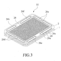
- Fig. 3 is a schematic view showing a cross-section of a modulized single cell of a fuel cell according to the present invention
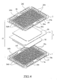
- Fig. 4 is an exploded view showing the components of the single cell of Fig. 3 ;
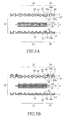
- Figs. 5A to 5D are cross-sectional views showing the assembly of the single cell according to a first embodiment of the present invention.
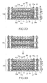
- Figs. 6A to 6B are cross-sectional views showing the stacking of two single cells of Fig. 5D to form a fuel cell module in accordance with a second embodiment of the present invention
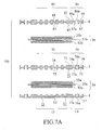
- Figs. 7A to 7D are cross-sectional views showing the assembly of the cell module according to a third embodiment of the present invention.
- Figs. 8A to 8B are cross-sectional views showing the stacking of two cell modules of Fig. 7D to form a fuel cell stack in accordance with a fourth embodiment of the present invention.
- Fig. 3 shows a modulized single cell 10 of a Proton Exchange Membrane Fuel Cell (PEMFC) according to the present invention.
- Fig. 4 is an exploded view showing the components of the modulized single cell 10 and
- Fig. 5A is a cross-sectional view of the components.
- PEMFC Proton Exchange Membrane Fuel Cell
- the modulized single cell 10 includes an anode plate 1 and a cathode plate 2, serving as separator plates for the fuel cell.
- the anode plate 1 has a first surface 11, a second surface 12, a central portion 13 and a circumferential portion 14.
- the central portion 13 on the first surface 11 is formed with a plurality of anode gas channels 15 having predetermined layout for hydrogen flowing therethrough.
- the circumferential portion 14 of the anode plate 1 is formed with a hydrogen inlet port 16a, a hydrogen outlet port 16b, an air inlet port 16c, an air outlet port 16d, a coolant inlet port 16e and a coolant outlet port 16f.
- the second surface 12 of the anode plate 1 is generally flat in structure.
- the cathode plate 2 has a first surface 21, a second surface 22, a central portion 23 and a circumferential portion 24.
- the central portion 23 on the second surface 22 is formed with a plurality of cathode gas channels 25 having predetermined layout for air flowing therethrough.
- the circumferential portion 24 of the cathode plate 2 is formed with a hydrogen inlet port 26a, a hydrogen outlet port 26b, an air inlet port 26c, an air outlet port 26d, a coolant inlet port 26e, and a coolant outlet port 26f.
- the hydrogen inlet port 26a, the hydrogen outlet port 26b, the air inlet port 26c, the air outlet port 26d, the coolant inlet port 26e, and the coolant outlet port 26f at the circumferential portion 24 of the cathode plate 2 are located oppositely and communicated respectively with the hydrogen inlet port 16a, the hydrogen outlet port 16b, the air inlet port 16c, the air outlet port 16d, the coolant inlet port 16e and the coolant outlet port 16f at the circumferential portion 14 of the anode plate 1, forming passages for flowing of hydrogen, air, and coolant respectively.
- a membrane electrode assembly (MEA) 3 is mounted between the anode plate 1 and cathode plate 2.
- the MEA 3 has an anode gas diffusion layer (GDL) 32, a proton exchange membrane (PEM) 31 and a cathode gas diffusion layer (GDL) 33, that are sequentially stacked and lo.cated between the central portion 13 of the anode plate 1 and the central portion 23 of the cathode plate 2.
- GDL anode gas diffusion layer
- PEM proton exchange membrane
- GDL cathode gas diffusion layer
- An anode catalytic layer (not shown) is coated between the anode GDL 32 and the PEM 31, and a cathode catalytic layer (not shown) is coated between the PEM 31 and the cathode GDL 33, such that the hydrogen introduced through the channels 15 of the anode plate 1 and the oxygen introduced through the channels 25 of the cathode plate 2 are adapted to proceed with the reverse reaction of the electrolytic dissociation of water.
- the first surface 11 of the circumferential portion 14 of the anode plate 1 is formed with a peripheral groove 17. Also, an extended groove 17a is formed in the vicinity of the ports 16a, 16b, 16c, 16d, 16e, 16f and communicated with the peripheral groove 17.
- the second surface 22 of the circumferential portion 24 of the cathode plate 2 facing the anode plate 1 is formed with a peripheral groove 27.
- An extended groove 27a is formed in the vicinity the ports 26a, 26b, 26c, 26d, 26e, 26f and communicated with the peripheral groove 27.
- the first surface 21 of the central portion 23 of the cathode plate 2 is also formed with a plurality of coolant channels 28 having predetermined layout for coolant flowing therethrough.
- the first surface 21 at the circumferential portion 24 of the cathode plate 2 is formed with a peripheral groove 29.
- An extended groove 29a is formed in the vicinity of the ports 26a, 26b, 26c, 26d, 26e, 26f and communicated with the peripheral groove 29.
- the silicon rubber 5 at the peripheral groove 17 of the anode plate 1 binds to the silicon rubber 6 at the peripheral groove 27 of the cathode plate 2, forming a tight sealing at the circumferential portion 14 between the anode plate 1 and cathode plate 2.
- the PEM 31 of the MEA 3 is adhered by the silicon rubber 5a at the extended groove 17a of the anode plate 1 and the silicon rubber 6a at the extended groove 27a of the cathode plate 2.
- the PEM 31 is stably located in position between the anode plate 1 and the cathode plate 2, and tight sealing are formed around the ports between the anode plate 1 and cathode plate 2 after the silicon rubbers are cured.
- each of the ports 16a, 16b, 16c, 16d, 16e, 16f at the anode plate 1 is only in communication respectively with the corresponding ports 26a, 26b, 26c, 26d, 26e, 26f at the cathode plate 2. Accordingly, a modulized unitary single cell 10 is formed.
- the single cell 10 is tightly sealed at the circumferential portion.
- the anode plate, MEA and cathode plate are stably positioned and fastened to each other. Sealing is provided between the ports of the anode plate and cathode plate, forming a plurality of separate passages. Thereby, hydrogen gas, oxygen gas and coolant are separately transported and sealed from leakage.
- silicon rubber is used as the adhesive material for binding the separator plates of the single cell 10.
- the silicon rubber is selected from material which has non-corrosive electronic grade and can be cured under moisture or heat.
- the silicon rubber made of heat-cured material in the event that the silicon rubber made of heat-cured material is utilized for the manufacture of the single cell, the silicon rubber generally has a heat-cured temperature of 100-140°C. Because the curing temperature of the silicon rubber is higher than the working temperature (lower than 100°C) of PEMFC, the silicon rubber is stable and can perform an optimal after-cured effect thereof. Preferably, to provide an optimal sealing and positioning effect, the viscosity of the silicon rubber utilized is greater than 150,000 centi-poise. Furthermore, the silicon rubber having a dielectric strength ranging from 15-20 V/mil would sufficiently perform a considerable electricity resistance. Nevertheless, the above-mentioned values are proposed for people skilled in this field to implement the present invention under a preferred situation. It dos not mean that any values going beyond the proposed ranges cannot perform well the expected functions as set forth therein.
- Fig. 6a shows a cross-sectional view of a second embodiment of the present invention, in which two single cells are superimposed to form a fuel cell module.
- Two modulized single cells 10, 10a are formed in accordance with the technology as mentioned. Please refer to Fig. 6B .
- the single cells 10, 10a are then stacked together, such that the anode plate 1 at the bottom of the second single cell 10a is superimposed on the top of the cathode plate 2 of the first single cell 10.
- the plane structure of the second surface of the anode plate of the second single cell 10a forms the top surface of the coolant channels on the first surface 21 of the cathode plate 2, providing a passage for coolant flowing therethrough.
- the silicon rubbers 4, 4a which are previously applied at the first surface 21 of the cathode plate 2 of the first single cell 10 and by compressing the two modulized single cells 10, 10a with a predetermined compression pressure, the two single cells 10, 10a are stably bound together and the coolant channels 28 are tightly sealed.
- Fig. 7A is a cross-sectional view showing the cell module constructed in accordance with a third embodiment of the present invention.
- the cell module comprises two MEAs, one bipolar plate, an anode plate and a cathode plate. Similar reference numerals are used to identify elements that are similar or identical as that in Figs. 5A to 5D .
- the cell module 10b comprises an anode plate 1, a bipolar plate 7 and a first MEA 3a.
- the anode plate 1 has a first surface 11, a second surface 12, a central portion 13, a circumferential portion 14, a plurality of anode gas channels 15, a peripheral groove 17, an extended groove 17a, and a plurality of ports.
- the bipolar plate 7 comprises a first surface 71, a second surface 72, a central portion 73, a peripheral portion 74, a plurality of cathode gas channels 75, a peripheral groove 77, an extended groove 77a, a peripheral groove 79, an extended groove 79a, and a plurality of ports.
- the first surface 71 of the central portion 73 is formed with a plurality of anode gas channels 78 for anode gas flowing therethrough.
- the first MEA 3a comprises a proton exchange membrane 31a, an anode gas diffusion layer 32a and a cathode gas diffusion layer 33a.
- a second MEA 3b is stacked on the first surface 71 of the bipolar plate 7.
- the second MEA 3b comprises a proton exchange membrane 31b, an anode gas diffusion layer 32b and a cathode gas diffusion layer 33b, in which the anode gas diffusion layer 32b of the second MEA 3b is superimposed on the central portion 73 at the first surface 71 of the bipolar plate 7.
- a cathode plate 8 is then stacked on the top of the anode gas diffusion layer 33b of the second MEA 3b.
- the cathode plate 8 includes a first surface 81, a second surface 82, a central portion 83, a circumferential portion 84, a plurality of cathode gas channels 85, a peripheral groove 87 and an extended groove 87a formed at the second surface 82, a peripheral groove 89 and an extended groove 89a formed at the first surface 81 and a plurality of ports. Also, a plurality of coolant channels 88 are formed at the first surface 81 of the central portion 83 of the cathode plate 8 for coolant flowing therethrough.
- the peripheral groove 89 and extended groove 89a at the first surface 81 of the circumferential portion 84 are dispensed with silicon rubbers 91, 91a, as shown in Fig. 7B .
- the silicon rubbers 91, 91a are cured.
- the peripheral groove 17 and extended groove 17a of the anode plate 1 are applied with silicon rubbers 92, 92a.
- the peripheral grooves 77, 79 and extended grooves 77a, 79a of the bipolar plate 7 and the peripheral groove 87 and extended groove 87a of the cathode plate 8 are respectively applied with silicon rubbers 93, 94, 93a, 94a, 95, 95a.
- the anode plate 1, first MEA 3a, bipolar plate 7, second MEA 3b, and cathode plate 8 are precisely stacked in proper order and compressed with a predetermined compression pressure, as shown in Fig. 7D .
- the silicon rubbers 92, 93, 94, 95 on each plate stick to the corresponding silicon rubbers at the opposing surface and is cured to form a tight sealing.
- the sealing tightly seal the circumferential portions among the anode plate 1, bipolar plate 7 and cathode plate 8.
- the silicon rubbers 92a, 93a correspondingly stick to the proton exchange membrane 31a of the first MEA 3a and the silicon rubbers 94a, 95a correspondingly stick to the proton exchange membrane 31b of the second MEA 3b, such that the first and second MEA 3a, 3b are stably anchored in position and sealings are formed around the ports between adjacent plates.
- an integrated modularized cell module 10b is formed.
- Figs. 8A to 8B are cross-sectional views showing the stacking of two cell modules of Fig. 7D to form a fuel cell stack in accordance with a fourth embodiment of the present invention.
- two cell modules 10b, 10c manufactured by the technology are stacked together in series, such that the second surface of the anode plate of the cell module 10c is superimposed on the first surface of the cathode plate of cell module 10b, as shown in Fig. 8b .
- the flat structure of the second surface of the anode plate of cell module 10c forms the top surface of the coolant channels on the first surface of the cathode plate 8.
- the silicon rubbers 91, 91a applied at the first surface of the cathode plate 8 of the cell module 10b, and by compressing the two cell modules 10b, 10c with a predetermined compression pressure, the two cell modules are bound together, forming a tight structure. Hence, the coolant channels are tightly sealed for flowing of coolant therethrough.
Landscapes
- Life Sciences & Earth Sciences (AREA)
- Engineering & Computer Science (AREA)
- Manufacturing & Machinery (AREA)
- Sustainable Development (AREA)
- Sustainable Energy (AREA)
- Chemical & Material Sciences (AREA)
- Chemical Kinetics & Catalysis (AREA)
- Electrochemistry (AREA)
- General Chemical & Material Sciences (AREA)
- Fuel Cell (AREA)
Abstract
Description
- 1. Field of the Invention
- The present invention relates to a proton exchange membrane fuel cell, particularly to a sealing structure for sealing single fuel cell and stacked fuel cell module.
- 2. Description of the Prior Art
- In the field of fuel cell technology, fuel cell is classified based on the electrolyte thereof. There are approximately five kinds of fuel cells which have been developed, namely, proton exchange membrane fuel cell or polymer electrolyte membrane fuel cell, abbreviated as PEMFC, alkaline fuel cell (AFC), phosphoric acid fuel cell (PAFC), molten carbonate fuel cell (MCFC) and solid oxide fuel cell (SOFC). Each kind of fuel cell has its own advantages, disadvantages and extent of applications. Among these known fuel cells, the PEMFC would be the most competitive power supply and has high practical value.
- Principally, a fuel cell is directed to use hydrogen and oxygen to proceed with electrochemical reactions to produce water and release electrical energy, which can be basically considered a reverse device of water electrolysis.
- The performance of fuel cell mainly depends on the extent of the electrochemical reaction, which is affected by the materials forming the layers of the fuel cell and the sealing between the plates. Hence, the selections of the materials and prevention of leakage between the layers will be the important factors of the performance of the fuel cell operations.
- However, although much effort has been put to settle the aforesaid problems, the result is not satisfied. Generally speaking, there are two reasons adversely affecting the precise control: one is a failure to efficiently perform the leak and pollution proof functions between the anode and cathode bipolar plates, and the other is a failure to properly control the conductive compression pressure between each layer under an optimal status.
- Please refer to
Fig. 1 which shows a cross-sectional view of the single cell of a prior art PEMFC. As shown, the single cell is constituted by an anode plate 101 and a cathode plate 102. Basically, an anode gas diffusion layer 104 and a cathode gas diffusion layer 105 are separately provided on the two sides of a proton exchange membrane (PEM) 103, forming a membrane electrode assembly (MEA). The MEA is mounted between the anode plate 101 and the cathode plate 102. - The inner surface of the anode plate 101 facing the MEA is formed with a plurality of anode gas channels 101a, and the inner surface of the cathode plate 102 facing the MEA is formed with a plurality of cathode gas channels 102a. The anode plate 101 and cathode plate 102 are separately provided with gaskets 106, 107 along edge portions thereof. The n, the MEA is disposed on a central portion of the anode plate 101 and cathode plate 102, forming a gastight single cell.
- Practically, a plurality of such single cells are stacked to configure a fuel cell stack as shown in
Fig. 2 . After the connections of plural manifolds or through holes adapted to supply gases and coolant and the dispositions of anupper end plate 108a and alower end plate 108b, together with theconductive terminals tie rods 110 therethrough. - However, this construction for the fuel cell will result in the following problems:
- (1) The hydrogen supplied from the channels 101a of the anode plate 101 tends to leak out due to the gaps between the gasket 106 and the anode plate 101. Meanwhile, the oxygen or air supplied from the channels 102a of the cathode plate 102 also tends to leak out due to the gaps between the gasket 107 and the cathode plate 102. The leakage of hydrogen and oxygen significantly affects the electrochemical reactions of the fuel cell. This disadvantageous phenomenon will be extremely obvious after a considerable duration of using the gaskets 106, 107. Integral formation of those gaskets 106, 107 into a single gasket may improve the situation, but it cannot thoroughly solve the problem.
- (2) Due to the property of the materials employed for the gaskets 106, 107 and the different aging rates of the gaskets, the compression pressure at the region of the gaskets is uneven, and hence the compression pressure in the whole fuel cell becomes uneven. This is why the reaction gases often fail to diffuse uniformly, which is a severe block to the conductivity of a PEMFC. Furthermore, because the whole PEMFC relies on the
tie rods 110 disposed circumferentially to control its compression pressure, the pressure of the circumferential portion is significantly different from that of the central portion, which will adversely affect the operational effects of the fuel cell. - (3) Utilizing a gasket between the plates fails to efficiently isolate pollution and fails to properly locate each layer in position. Further, because it is difficult to control in advance the compression pressure at an optimal range, it is not possible to pre-prepare a stock of the single cells in the modulized form to proceed with any of the possible types of tests for the purposes of cost reduction and mass production. This is really the key factor of the failure to widely and effectively apply PEMFCs in the industry nowadays.
- Accordingly, to provide a highly efficient, mass-producible and cost-saving modulized single cell and cell module to solve the above-mentioned problems and further supply breakthrough ideas in manufacturing the PEMFC is a common desire of people skilled in this field.
- The primary objective of this invention is to provide a single cell of a fuel cell, particularly a single cell of a PEMFC or a module thereof assembled by the single cells, by means of modulizing and unitizing the cell and module, to simplify the manufacturing process of a PEMFC. Because it is possible to test the performance of each single cell or module in advance according to this invention, the quality of the whole fuel cell is significantly improved and the manufacturing cost thereof is reduced to a mass production scale, thereby practically replacing the existing energy.
- Another objective of this invention is to provide a sealing structure for a fuel cell assembled by a plurality of modulized single cells or modules. By means of dispensing a desired amount of silicon rubber between the circumferential portions of the anode plate and cathode plate, the two plates and the MEA sandwiched therebetween can be well positioned in a cushioned manner and can be controlled under a predetermined compression pressure in advance before the silicon rubber is cured, thereby ensuring that a high quality single cell and module is obtained.
- Yet a further object of this invention is to provide a single cell of a fuel cell or a module comprising the single cells with excellent gastight effect. By means of dispensing silicon rubber between plates, the leakage of the gases and liquid guided through the channels on the plates can therefore be avoided.
- To achieve the above objects, in accordance with the present invention, there is provided a sealing structure for sealing a proton exchange membrane fuel cell. The fuel cell includes a membrane electrode assembly, an anode plate, and a cathode plate. Both of the plates are formed with a peripheral groove and an extended groove at a circumferential portion thereof, and silicon rubber is applied to the peripheral groove and the extended groove. Before the silicon rubber is cured, the anode plate, the membrane electrode assembly and the cathode plate are stacked and compressed with a predetermined compression pressure, such that the silicon rubber at the peripheral groove of the anode plate binds correspondingly to the silicon rubber at the peripheral groove of the cathode plate to form a tight sealing at the circumferential portions between the anode plate and the cathode plate, and the membrane electrode assembly is tightly sandwiched between the silicon rubber at the extended groove of the anode plate and the silicon rubber at the extended groove of the cathode plate to form a tight sealing around the ports between the anode plate and cathode plate.
- The detailed technology and preferred embodiments implemented for the subject invention are described in the following paragraphs accompanying the appended drawings for people skilled in this field to well appreciate the features of the claimed invention.
-
Fig. 1 is a schematic view showing a cross-section of the single cell of a prior art fuel cell; -
Fig. 2 is a perspective view of an assembled prior art fuel cell stack; -
Fig. 3 is a schematic view showing a cross-section of a modulized single cell of a fuel cell according to the present invention; -
Fig. 4 is an exploded view showing the components of the single cell ofFig. 3 ; -
Figs. 5A to 5D are cross-sectional views showing the assembly of the single cell according to a first embodiment of the present invention; -
Figs. 6A to 6B are cross-sectional views showing the stacking of two single cells ofFig. 5D to form a fuel cell module in accordance with a second embodiment of the present invention; -
Figs. 7A to 7D are cross-sectional views showing the assembly of the cell module according to a third embodiment of the present invention; and -
Figs. 8A to 8B are cross-sectional views showing the stacking of two cell modules ofFig. 7D to form a fuel cell stack in accordance with a fourth embodiment of the present invention. - Please refer to the drawings and in particular to
Fig. 3. Fig. 3 shows a modulizedsingle cell 10 of a Proton Exchange Membrane Fuel Cell (PEMFC) according to the present invention.Fig. 4 is an exploded view showing the components of the modulizedsingle cell 10 andFig. 5A is a cross-sectional view of the components. - Of course, the technical concept is not restricted to a PEMFC. The modulization technology of the subject invention is applicable to any type of fuel cell having similar construction.
- The modulized
single cell 10 includes ananode plate 1 and acathode plate 2, serving as separator plates for the fuel cell. Theanode plate 1 has afirst surface 11, asecond surface 12, acentral portion 13 and acircumferential portion 14. Thecentral portion 13 on thefirst surface 11 is formed with a plurality ofanode gas channels 15 having predetermined layout for hydrogen flowing therethrough. Thecircumferential portion 14 of theanode plate 1 is formed with ahydrogen inlet port 16a, ahydrogen outlet port 16b, anair inlet port 16c, anair outlet port 16d, acoolant inlet port 16e and acoolant outlet port 16f. In the embodiment, thesecond surface 12 of theanode plate 1 is generally flat in structure. - Similarly, the
cathode plate 2 has afirst surface 21, asecond surface 22, acentral portion 23 and acircumferential portion 24. Thecentral portion 23 on thesecond surface 22 is formed with a plurality ofcathode gas channels 25 having predetermined layout for air flowing therethrough. Thecircumferential portion 24 of thecathode plate 2 is formed with ahydrogen inlet port 26a, ahydrogen outlet port 26b, anair inlet port 26c, anair outlet port 26d, acoolant inlet port 26e, and acoolant outlet port 26f. - When the
cathode plate 2 is superimposed on theanode plate 1, thehydrogen inlet port 26a, thehydrogen outlet port 26b, theair inlet port 26c, theair outlet port 26d, thecoolant inlet port 26e, and thecoolant outlet port 26f at thecircumferential portion 24 of thecathode plate 2 are located oppositely and communicated respectively with thehydrogen inlet port 16a, thehydrogen outlet port 16b, theair inlet port 16c, theair outlet port 16d, thecoolant inlet port 16e and thecoolant outlet port 16f at thecircumferential portion 14 of theanode plate 1, forming passages for flowing of hydrogen, air, and coolant respectively. - A membrane electrode assembly (MEA) 3 is mounted between the
anode plate 1 andcathode plate 2. TheMEA 3 has an anode gas diffusion layer (GDL) 32, a proton exchange membrane (PEM) 31 and a cathode gas diffusion layer (GDL) 33, that are sequentially stacked and lo.cated between thecentral portion 13 of theanode plate 1 and thecentral portion 23 of thecathode plate 2. An anode catalytic layer (not shown) is coated between theanode GDL 32 and thePEM 31, and a cathode catalytic layer (not shown) is coated between thePEM 31 and thecathode GDL 33, such that the hydrogen introduced through thechannels 15 of theanode plate 1 and the oxygen introduced through thechannels 25 of thecathode plate 2 are adapted to proceed with the reverse reaction of the electrolytic dissociation of water. - The
first surface 11 of thecircumferential portion 14 of theanode plate 1 is formed with aperipheral groove 17. Also, anextended groove 17a is formed in the vicinity of theports peripheral groove 17. - Similarly, the
second surface 22 of thecircumferential portion 24 of thecathode plate 2 facing theanode plate 1 is formed with aperipheral groove 27. Anextended groove 27a is formed in the vicinity theports peripheral groove 27. - In this embodiment, the
first surface 21 of thecentral portion 23 of thecathode plate 2 is also formed with a plurality ofcoolant channels 28 having predetermined layout for coolant flowing therethrough. Thefirst surface 21 at thecircumferential portion 24 of thecathode plate 2 is formed with aperipheral groove 29. Anextended groove 29a is formed in the vicinity of theports peripheral groove 29. - In the assembly of the
single cell 10, appropriate amounts ofsilicon rubbers peripheral groove 29 and theextended groove 29a at thefirst surface 21 of thecathode plate 2 and cured, as shown inFig. 5B . - Then, appropriate amounts of
silicon rubbers peripheral groove 17 and theextended groove 17a at thefirst surface 11 of thecircumferential portion 14 of theanode plate 1. As shown inFig. 5C , appropriate amounts ofsilicon rubbers peripheral groove 27 andextended groove 27a at thesecond surface 22 of thecircumferential portion 24 of thecathode plate 2. It is shown inFig. 5D that after the application of thesilicon rubbers silicon rubbers membrane electrode assembly 3 is sandwiched precisely between thecentral portion 13 of theanode plate 1 and thecentral portion 23 of thecathode plate 2 and the structure is compressed with a predetermined compression pressure. Accordingly, thesilicon rubber 5 at theperipheral groove 17 of theanode plate 1 binds to thesilicon rubber 6 at theperipheral groove 27 of thecathode plate 2, forming a tight sealing at thecircumferential portion 14 between theanode plate 1 andcathode plate 2. - Moreover, the
PEM 31 of theMEA 3 is adhered by thesilicon rubber 5a at theextended groove 17a of theanode plate 1 and thesilicon rubber 6a at theextended groove 27a of thecathode plate 2. Thereby, thePEM 31 is stably located in position between theanode plate 1 and thecathode plate 2, and tight sealing are formed around the ports between theanode plate 1 andcathode plate 2 after the silicon rubbers are cured. Thereby, each of theports anode plate 1 is only in communication respectively with the correspondingports cathode plate 2. Accordingly, a modulized unitarysingle cell 10 is formed. - By means of the described technology, the
single cell 10 is tightly sealed at the circumferential portion. Moreover, the anode plate, MEA and cathode plate are stably positioned and fastened to each other. Sealing is provided between the ports of the anode plate and cathode plate, forming a plurality of separate passages. Thereby, hydrogen gas, oxygen gas and coolant are separately transported and sealed from leakage. - In the embodiment, silicon rubber is used as the adhesive material for binding the separator plates of the
single cell 10. Preferably, the silicon rubber is selected from material which has non-corrosive electronic grade and can be cured under moisture or heat. - According to experimental and practical experiences, in the event that the silicon rubber made of heat-cured material is utilized for the manufacture of the single cell, the silicon rubber generally has a heat-cured temperature of 100-140°C. Because the curing temperature of the silicon rubber is higher than the working temperature (lower than 100°C) of PEMFC, the silicon rubber is stable and can perform an optimal after-cured effect thereof. Preferably, to provide an optimal sealing and positioning effect, the viscosity of the silicon rubber utilized is greater than 150,000 centi-poise. Furthermore, the silicon rubber having a dielectric strength ranging from 15-20 V/mil would sufficiently perform a considerable electricity resistance. Nevertheless, the above-mentioned values are proposed for people skilled in this field to implement the present invention under a preferred situation. It dos not mean that any values going beyond the proposed ranges cannot perform well the expected functions as set forth therein.
- In practical application, one can assemble a plurality of single cells as mentioned above and superimpose them onto one another to form a cell module for performing high power output.
-
Fig. 6a shows a cross-sectional view of a second embodiment of the present invention, in which two single cells are superimposed to form a fuel cell module. Two modulizedsingle cells Fig. 6B . Thesingle cells anode plate 1 at the bottom of the secondsingle cell 10a is superimposed on the top of thecathode plate 2 of the firstsingle cell 10. Accordingly, the plane structure of the second surface of the anode plate of the secondsingle cell 10a forms the top surface of the coolant channels on thefirst surface 21 of thecathode plate 2, providing a passage for coolant flowing therethrough. By means of thesilicon rubbers first surface 21 of thecathode plate 2 of the firstsingle cell 10 and by compressing the two modulizedsingle cells single cells coolant channels 28 are tightly sealed. -
Fig. 7A is a cross-sectional view showing the cell module constructed in accordance with a third embodiment of the present invention. In the example shown, the cell module comprises two MEAs, one bipolar plate, an anode plate and a cathode plate. Similar reference numerals are used to identify elements that are similar or identical as that inFigs. 5A to 5D . - In this embodiment, the
cell module 10b comprises ananode plate 1, abipolar plate 7 and afirst MEA 3a. Theanode plate 1 has afirst surface 11, asecond surface 12, acentral portion 13, acircumferential portion 14, a plurality ofanode gas channels 15, aperipheral groove 17, anextended groove 17a, and a plurality of ports. Thebipolar plate 7 comprises afirst surface 71, asecond surface 72, acentral portion 73, aperipheral portion 74, a plurality ofcathode gas channels 75, aperipheral groove 77, anextended groove 77a, aperipheral groove 79, anextended groove 79a, and a plurality of ports. Furthermore, thefirst surface 71 of thecentral portion 73 is formed with a plurality ofanode gas channels 78 for anode gas flowing therethrough. Thefirst MEA 3a comprises aproton exchange membrane 31a, an anodegas diffusion layer 32a and a cathodegas diffusion layer 33a. - A
second MEA 3b is stacked on thefirst surface 71 of thebipolar plate 7. Thesecond MEA 3b comprises aproton exchange membrane 31b, an anodegas diffusion layer 32b and a cathodegas diffusion layer 33b, in which the anodegas diffusion layer 32b of thesecond MEA 3b is superimposed on thecentral portion 73 at thefirst surface 71 of thebipolar plate 7. Acathode plate 8 is then stacked on the top of the anodegas diffusion layer 33b of thesecond MEA 3b. - The
cathode plate 8 includes afirst surface 81, asecond surface 82, acentral portion 83, acircumferential portion 84, a plurality ofcathode gas channels 85, aperipheral groove 87 and anextended groove 87a formed at thesecond surface 82, aperipheral groove 89 and anextended groove 89a formed at thefirst surface 81 and a plurality of ports. Also, a plurality ofcoolant channels 88 are formed at thefirst surface 81 of thecentral portion 83 of thecathode plate 8 for coolant flowing therethrough. - In the manufacture of the
cell module 10b, theperipheral groove 89 andextended groove 89a at thefirst surface 81 of thecircumferential portion 84 are dispensed withsilicon rubbers Fig. 7B . The silicon rubbers 91, 91a are cured. - Then, the
peripheral groove 17 andextended groove 17a of theanode plate 1 are applied withsilicon rubbers peripheral grooves extended grooves bipolar plate 7 and theperipheral groove 87 andextended groove 87a of thecathode plate 8 are respectively applied withsilicon rubbers anode plate 1,first MEA 3a,bipolar plate 7,second MEA 3b, andcathode plate 8 are precisely stacked in proper order and compressed with a predetermined compression pressure, as shown inFig. 7D . The silicon rubbers 92, 93, 94, 95 on each plate stick to the corresponding silicon rubbers at the opposing surface and is cured to form a tight sealing. The sealing tightly seal the circumferential portions among theanode plate 1,bipolar plate 7 andcathode plate 8. Besides, thesilicon rubbers proton exchange membrane 31a of thefirst MEA 3a and thesilicon rubbers proton exchange membrane 31b of thesecond MEA 3b, such that the first andsecond MEA modularized cell module 10b is formed. -
Figs. 8A to 8B are cross-sectional views showing the stacking of two cell modules ofFig. 7D to form a fuel cell stack in accordance with a fourth embodiment of the present invention. In assembly, twocell modules cell module 10c is superimposed on the first surface of the cathode plate ofcell module 10b, as shown inFig. 8b . Accordingly, the flat structure of the second surface of the anode plate ofcell module 10c forms the top surface of the coolant channels on the first surface of thecathode plate 8. By means of the silicon rubbers 91, 91a applied at the first surface of thecathode plate 8 of thecell module 10b, and by compressing the twocell modules - The above disclosure is related to the detailed technical contents and inventive features thereof. People skilled in this field may proceed with a variety of modifications and replacements based on the disclosures and suggestions of the invention as described without departing from the characteristics thereof. Nevertheless, although such modifications and replacements are not fully disclosed in the above descriptions, they have substantially been covered in the following claims as appended.
Claims (3)
- A sealing structure for sealing a fuel cell module (10b), comprising:at least a first membrane electrode assembly (3a) and at least a second membrane electrode assembly (3b), each membrane electrode assembly (3a, 3b) including an anode side with an anode gas diffusion layer (32a, 32b), a cathode side with a cathode gas diffusion layer (33a, 33b), and at least a proton exchange membrane (31 a, 31b) mounted between the anode gas diffusion layer (32a, 32b) and the cathode gas diffusion layer (33a, 33b);at least one bipolar plate (7), sandwiched between the membrane electrode assemblies (3a, 3b), the bipolar plate (7) including a first surface (71), a second surface (72), a central portion (73), a circumferential portion (74) and a plurality of ports (76a) formed at the circumferential portion (74), in which the first surface (71) of the central portion (73) is formed with a plurality of anode gas channels (78) and the second surface (72) of the central portion (73) is formed with a plurality of cathode gas channels (75); and the circumferential portions (74) of the first surface (71) and second surface (72) are formed with a peripheral groove (79,77) and an extended groove (79a, 77a) around the ports (76a) in communication with the peripheral groove (79, 77);an anode plate (1) mounted to the anode gas diffusion layer (32a) of the first membrane electrode assembly (3a), which comprises a first surface (11) facing to the anode gas diffusion layer (32a) of the first membrane electrode assembly (3a), a central portion (13), a circumferential portion (14) and a plurality of ports (16a) formed at the circumferential portion (14), in which the first surface (11) is formed with a plurality of anode gas channels (15) at the central portion (13), a peripheral groove (17) at the circumferential portion (14) and an extended groove (17a) around the ports (16a) in communication with the peripheral groove (17); anda cathode plate (8) mounted to the cathode gas diffusion layer (33b) of the second membrane electrode assembly (3b), which comprises a first surface (81), a second surface (82) facing to the cathode gas diffusion layer (33b) of the second membrane electrode assembly (3b), a central portion (83), a circumferential portion (84) and a plurality of ports (86a) formed at the circumferential portion (84), in which the second surface (82) is formed with a plurality of cathode gas channels (85) at the central portion (83), a peripheral groove (87) at the circumferential portion (84) and an extended groove (87a) around the ports (86a) in communication with the peripheral groove (87); characterized in thatsilicone rubbers (92) at the peripheral groove (17) on the first side (11) of the anode plate (1) binds correspondingly to silicone rubbers (93) at the peripheral groove (77) on the second side (72) of the bipolar plate (7) to form a tight seal at the circumferential portions (14, 74) between the anode plate (1) and the bipolar plate (7), and the proton exchange membrane (31a) of the membrane electrode assembly (3a) has an entire periphery thereof tightly sandwiched between and surrounded by the silicone rubber (92a) at the extended groove (17a) of the anode plate (1) and the silicone rubber (93a) at the extended groove (77a) of the bipolar plate (7) to form a tight seal around the ports (16a,76a) between the anode plate (1) and the bipolar plate (7); andsilicone rubbers (95) at the peripheral groove (87) on the second side (82) of the cathode plate (8) binds correspondingly to silicone rubbers (94) at the peripheral groove (79) on the first side (71) of the bipolar plate (7) to form a tight seal at the circumferential portions (74,84) between the cathode plate (8) and the bipolar plate (7), and the proton exchange membrane (31b) of the second membrane electrode assembly (3b) has an entire periphery thereof tightly sandwiched between and surrounded by the silicone rubber (95a) at the extended groove (87a) of the cathode plate (8) and the silicone rubber (94a) at the extended groove (79a) of the bipolar plate (7) to form a tight seal around the ports (76a, 86a) between the cathode plate (8) and the bipolar plate (7).
- The fuel cell module as claimed in Claim 1, characterized in that the first surface (81) of the cathode plate (8) further comprises a plurality of coolant channels (88) thereon.
- The fuel cell module as claimed in Claim 1, characterized in that the second surface (12) of the anode plate (1) has a flat structure.
Applications Claiming Priority (2)
| Application Number | Priority Date | Filing Date | Title |
|---|---|---|---|
| CNB2003101215962A CN100438132C (en) | 2003-12-29 | 2003-12-29 | Sealing structure of modularized proton exchange membrane fuel cell |
| EP04016256.2A EP1553652B1 (en) | 2003-12-29 | 2004-07-09 | Sealing structure for sealing separator plates of fuel cell modules |
Related Parent Applications (2)
| Application Number | Title | Priority Date | Filing Date |
|---|---|---|---|
| EP04016256.2 Division | 2004-07-09 | ||
| EP04016256.2A Division-Into EP1553652B1 (en) | 2003-12-29 | 2004-07-09 | Sealing structure for sealing separator plates of fuel cell modules |
Publications (2)
| Publication Number | Publication Date |
|---|---|
| EP2273593A2 true EP2273593A2 (en) | 2011-01-12 |
| EP2273593A3 EP2273593A3 (en) | 2011-09-21 |
Family
ID=34580584
Family Applications (2)
| Application Number | Title | Priority Date | Filing Date |
|---|---|---|---|
| EP04016256.2A Expired - Lifetime EP1553652B1 (en) | 2003-12-29 | 2004-07-09 | Sealing structure for sealing separator plates of fuel cell modules |
| EP10012866A Withdrawn EP2273593A3 (en) | 2003-12-29 | 2004-07-09 | Sealing structure for sealing separator plates of fuel cell modules |
Family Applications Before (1)
| Application Number | Title | Priority Date | Filing Date |
|---|---|---|---|
| EP04016256.2A Expired - Lifetime EP1553652B1 (en) | 2003-12-29 | 2004-07-09 | Sealing structure for sealing separator plates of fuel cell modules |
Country Status (2)
| Country | Link |
|---|---|
| EP (2) | EP1553652B1 (en) |
| CN (1) | CN100438132C (en) |
Cited By (1)
| Publication number | Priority date | Publication date | Assignee | Title |
|---|---|---|---|---|
| EP4628629A3 (en) * | 2024-04-01 | 2026-03-11 | Robert Bosch GmbH | Electrolytic unit and electrolytic stack |
Families Citing this family (22)
| Publication number | Priority date | Publication date | Assignee | Title |
|---|---|---|---|---|
| JP5087863B2 (en) * | 2006-06-09 | 2012-12-05 | トヨタ自動車株式会社 | Fuel cell |
| DE102006032530A1 (en) * | 2006-07-12 | 2008-01-17 | Carl Freudenberg Kg | Module for a fuel cell assembly |
| KR100785115B1 (en) | 2006-11-22 | 2007-12-11 | 현대자동차주식회사 | Separator coupling structure of fuel cell vehicle |
| CN100570942C (en) * | 2007-03-28 | 2009-12-16 | 南亚电路板股份有限公司 | Fuel Cell Module Structure |
| US8211585B2 (en) * | 2008-04-08 | 2012-07-03 | GM Global Technology Operations LLC | Seal for PEM fuel cell plate |
| US8911918B2 (en) | 2010-02-08 | 2014-12-16 | GM Global Technology Operations LLC | Hybrid seal application process |
| GB2502517A (en) * | 2012-05-28 | 2013-12-04 | Intelligent Energy Ltd | Fuel Cell Plate Assemblies and methods of assembly thereof |
| JP6024398B2 (en) * | 2012-11-06 | 2016-11-16 | 大日本印刷株式会社 | REINFORCED CATALYST LAYER-ELECTROLYTE MEMBRANE LAMINATE, SOLID POLYMER FUEL CELL AND METHOD FOR PRODUCING REINFORCING CATALYST LAYER-ELECTROLYTE MEMBRANE |
| CN102938468A (en) * | 2012-12-03 | 2013-02-20 | 新源动力股份有限公司 | A fuel cell reinforced sealing method |
| DE102016202481A1 (en) | 2016-02-18 | 2017-08-24 | Volkswagen Aktiengesellschaft | Fuel cell stack and method for producing such a fuel cell stack |
| CN105776446A (en) * | 2016-05-23 | 2016-07-20 | 汪万法 | Cell body-free electrolyzer |
| CN108767290A (en) * | 2018-05-28 | 2018-11-06 | 上海治臻新能源装备有限公司 | A kind of self-positioning package assembly for fuel cell assembly |
| CN109509894B (en) * | 2018-12-05 | 2024-03-12 | 国家电投集团氢能科技发展有限公司 | Single fuel cell and fuel cell stack |
| CN109524685B (en) * | 2018-12-05 | 2024-03-12 | 国家电投集团氢能科技发展有限公司 | Single fuel cell and fuel cell stack |
| CN109509892B (en) * | 2018-12-05 | 2024-02-23 | 国家电投集团氢能科技发展有限公司 | Fuel cell separator, unit fuel cell, and fuel cell stack |
| CN109980245B (en) * | 2019-03-22 | 2021-10-29 | 苏州钧峰新能源科技有限公司 | A sealing method of bipolar plate and membrane electrode in direct methanol fuel cell |
| CN110400944A (en) * | 2019-06-28 | 2019-11-01 | 上海电气集团股份有限公司 | A kind of encapsulating method and sealing structure of fuel cell membrane electrode and frame |
| CN110828844A (en) * | 2019-11-11 | 2020-02-21 | 上海骥翀氢能科技有限公司 | Cathode and anode flow field and bipolar plate of a high performance proton exchange membrane fuel cell |
| CN111106361B (en) * | 2019-12-23 | 2021-03-30 | 清华大学 | Fuel cell stacks, bipolar plates and gas diffusion layers |
| DE102023208234A1 (en) * | 2023-08-29 | 2025-03-06 | Cellcentric Gmbh & Co. Kg | BIPOLAR PLATE FOR A FUEL CELL |
| CN118996457B (en) * | 2024-10-24 | 2025-04-29 | 爱德曼氢能源装备有限公司 | Sealed PEM electrolysis trough monocell structure and contain its PEM electrolysis trough |
| CN119433557A (en) * | 2025-01-07 | 2025-02-14 | 上海氢盛创合能源科技有限公司 | PEM electrolyzer hydrogen production unit and manufacturing method thereof |
Family Cites Families (5)
| Publication number | Priority date | Publication date | Assignee | Title |
|---|---|---|---|---|
| JP2001118592A (en) * | 1999-10-18 | 2001-04-27 | Matsushita Electric Ind Co Ltd | Polymer electrolyte fuel cell and cell stack |
| CA2345852C (en) * | 2000-05-02 | 2008-11-18 | Honda Giken Kogyo Kabushiki Kaisha | Fuel cell having sealant for sealing a solid polymer electrolyte membrane |
| JP4923319B2 (en) | 2000-07-25 | 2012-04-25 | トヨタ自動車株式会社 | Fuel cell |
| JP4043724B2 (en) * | 2001-02-14 | 2008-02-06 | 本田技研工業株式会社 | Unit fuel cell and fuel cell stack manufacturing method |
| US6852439B2 (en) * | 2001-05-15 | 2005-02-08 | Hydrogenics Corporation | Apparatus for and method of forming seals in fuel cells and fuel cell stacks |
-
2003
- 2003-12-29 CN CNB2003101215962A patent/CN100438132C/en not_active Expired - Lifetime
-
2004
- 2004-07-09 EP EP04016256.2A patent/EP1553652B1/en not_active Expired - Lifetime
- 2004-07-09 EP EP10012866A patent/EP2273593A3/en not_active Withdrawn
Non-Patent Citations (1)
| Title |
|---|
| None |
Cited By (1)
| Publication number | Priority date | Publication date | Assignee | Title |
|---|---|---|---|---|
| EP4628629A3 (en) * | 2024-04-01 | 2026-03-11 | Robert Bosch GmbH | Electrolytic unit and electrolytic stack |
Also Published As
| Publication number | Publication date |
|---|---|
| CN100438132C (en) | 2008-11-26 |
| CN1635643A (en) | 2005-07-06 |
| EP2273593A3 (en) | 2011-09-21 |
| EP1553652B1 (en) | 2014-06-04 |
| EP1553652A3 (en) | 2007-04-18 |
| EP1553652A2 (en) | 2005-07-13 |
Similar Documents
| Publication | Publication Date | Title |
|---|---|---|
| CA2473870C (en) | Sealing structure for sealing separator plates of fuel cell modules | |
| EP1553652B1 (en) | Sealing structure for sealing separator plates of fuel cell modules | |
| US7070876B2 (en) | Membrane electrode assembly with integrated seal | |
| US7014940B2 (en) | High-polymer electrolyte fuel cell | |
| US8551671B2 (en) | Fuel cell fluid sealing structure | |
| US7405019B2 (en) | Polymer electrolyte fuel cell | |
| KR100413891B1 (en) | Fuel cell stack with separator of a laminate structure | |
| EP1286408A2 (en) | Modular single cell and assembled cell stack of a proton exchange membrane fuel cell | |
| US20110281193A1 (en) | Fuel cell fluid distribution system | |
| CN111244496B (en) | Fuel cell and flow distribution device | |
| JP2005502995A (en) | Modular fuel cell cartridge and stack | |
| US20020110720A1 (en) | Modulized single cell and assembled cell unit of a proton exchange membrane fuel cell | |
| US20100297533A1 (en) | Fuel cell and method of manufacturing same | |
| CN107994239B (en) | Flow channel cross-sectional design with more elastic contact pressure distribution on metal bead seal at intersection between bead and flow channel | |
| US20090291344A1 (en) | Fuel cell | |
| EP2012383A1 (en) | Mea member, and polyelectrolyte fuel cell | |
| US7824817B2 (en) | Fuel cell | |
| US20110008703A1 (en) | Fuel cell with dead-end anode | |
| US20080076005A1 (en) | Fuel cell fluid distribution system | |
| KR100808028B1 (en) | Equivalent large area fuel cell with flat array of cells and compression seal for use | |
| KR102875398B1 (en) | Fuel cell apparatus | |
| KR102927067B1 (en) | Fuel cell apparatus | |
| KR102899513B1 (en) | Fuel cell apparatus | |
| EP4557413A1 (en) | End assembly of a fuel cell stack and fuel cell stack | |
| CN211929634U (en) | Interface plate for fuel cell |
Legal Events
| Date | Code | Title | Description |
|---|---|---|---|
| PUAI | Public reference made under article 153(3) epc to a published international application that has entered the european phase |
Free format text: ORIGINAL CODE: 0009012 |
|
| AC | Divisional application: reference to earlier application |
Ref document number: 1553652 Country of ref document: EP Kind code of ref document: P |
|
| AK | Designated contracting states |
Kind code of ref document: A2 Designated state(s): AT BE BG CH CY CZ DE DK EE ES FI FR GB GR HU IE IT LI LU MC NL PL PT RO SE SI SK TR |
|
| PUAL | Search report despatched |
Free format text: ORIGINAL CODE: 0009013 |
|
| AK | Designated contracting states |
Kind code of ref document: A3 Designated state(s): AT BE BG CH CY CZ DE DK EE ES FI FR GB GR HU IE IT LI LU MC NL PL PT RO SE SI SK TR |
|
| RIC1 | Information provided on ipc code assigned before grant |
Ipc: H01M 8/24 20060101ALI20110812BHEP Ipc: H01M 8/02 20060101AFI20110812BHEP |
|
| STAA | Information on the status of an ep patent application or granted ep patent |
Free format text: STATUS: THE APPLICATION IS DEEMED TO BE WITHDRAWN |
|
| 18D | Application deemed to be withdrawn |
Effective date: 20120322 |