EP2273587A1 - Rechargeable battery - Google Patents
Rechargeable battery Download PDFInfo
- Publication number
- EP2273587A1 EP2273587A1 EP10167890A EP10167890A EP2273587A1 EP 2273587 A1 EP2273587 A1 EP 2273587A1 EP 10167890 A EP10167890 A EP 10167890A EP 10167890 A EP10167890 A EP 10167890A EP 2273587 A1 EP2273587 A1 EP 2273587A1
- Authority
- EP
- European Patent Office
- Prior art keywords
- electrode
- rechargeable battery
- plate
- tab
- battery
- Prior art date
- Legal status (The legal status is an assumption and is not a legal conclusion. Google has not performed a legal analysis and makes no representation as to the accuracy of the status listed.)
- Granted
Links
Images


Classifications
-
- H—ELECTRICITY
- H01—ELECTRIC ELEMENTS
- H01M—PROCESSES OR MEANS, e.g. BATTERIES, FOR THE DIRECT CONVERSION OF CHEMICAL ENERGY INTO ELECTRICAL ENERGY
- H01M10/00—Secondary cells; Manufacture thereof
- H01M10/42—Methods or arrangements for servicing or maintenance of secondary cells or secondary half-cells
-
- H—ELECTRICITY
- H01—ELECTRIC ELEMENTS
- H01M—PROCESSES OR MEANS, e.g. BATTERIES, FOR THE DIRECT CONVERSION OF CHEMICAL ENERGY INTO ELECTRICAL ENERGY
- H01M50/00—Constructional details or processes of manufacture of the non-active parts of electrochemical cells other than fuel cells, e.g. hybrid cells
- H01M50/10—Primary casings, jackets or wrappings of a single cell or a single battery
- H01M50/102—Primary casings, jackets or wrappings of a single cell or a single battery characterised by their shape or physical structure
- H01M50/103—Primary casings, jackets or wrappings of a single cell or a single battery characterised by their shape or physical structure prismatic or rectangular
-
- H—ELECTRICITY
- H01—ELECTRIC ELEMENTS
- H01M—PROCESSES OR MEANS, e.g. BATTERIES, FOR THE DIRECT CONVERSION OF CHEMICAL ENERGY INTO ELECTRICAL ENERGY
- H01M50/00—Constructional details or processes of manufacture of the non-active parts of electrochemical cells other than fuel cells, e.g. hybrid cells
- H01M50/10—Primary casings, jackets or wrappings of a single cell or a single battery
- H01M50/147—Lids or covers
- H01M50/148—Lids or covers characterised by their shape
- H01M50/15—Lids or covers characterised by their shape for prismatic or rectangular cells
-
- H—ELECTRICITY
- H01—ELECTRIC ELEMENTS
- H01M—PROCESSES OR MEANS, e.g. BATTERIES, FOR THE DIRECT CONVERSION OF CHEMICAL ENERGY INTO ELECTRICAL ENERGY
- H01M50/00—Constructional details or processes of manufacture of the non-active parts of electrochemical cells other than fuel cells, e.g. hybrid cells
- H01M50/10—Primary casings, jackets or wrappings of a single cell or a single battery
- H01M50/172—Arrangements of electric connectors penetrating the casing
- H01M50/174—Arrangements of electric connectors penetrating the casing adapted for the shape of the cells
- H01M50/176—Arrangements of electric connectors penetrating the casing adapted for the shape of the cells for prismatic or rectangular cells
-
- H—ELECTRICITY
- H01—ELECTRIC ELEMENTS
- H01M—PROCESSES OR MEANS, e.g. BATTERIES, FOR THE DIRECT CONVERSION OF CHEMICAL ENERGY INTO ELECTRICAL ENERGY
- H01M50/00—Constructional details or processes of manufacture of the non-active parts of electrochemical cells other than fuel cells, e.g. hybrid cells
- H01M50/10—Primary casings, jackets or wrappings of a single cell or a single battery
- H01M50/183—Sealing members
- H01M50/186—Sealing members characterised by the disposition of the sealing members
- H01M50/188—Sealing members characterised by the disposition of the sealing members the sealing members being arranged between the lid and terminal
-
- H—ELECTRICITY
- H01—ELECTRIC ELEMENTS
- H01M—PROCESSES OR MEANS, e.g. BATTERIES, FOR THE DIRECT CONVERSION OF CHEMICAL ENERGY INTO ELECTRICAL ENERGY
- H01M50/00—Constructional details or processes of manufacture of the non-active parts of electrochemical cells other than fuel cells, e.g. hybrid cells
- H01M50/30—Arrangements for facilitating escape of gases
- H01M50/342—Non-re-sealable arrangements
- H01M50/3425—Non-re-sealable arrangements in the form of rupturable membranes or weakened parts, e.g. pierced with the aid of a sharp member
-
- H—ELECTRICITY
- H01—ELECTRIC ELEMENTS
- H01M—PROCESSES OR MEANS, e.g. BATTERIES, FOR THE DIRECT CONVERSION OF CHEMICAL ENERGY INTO ELECTRICAL ENERGY
- H01M50/00—Constructional details or processes of manufacture of the non-active parts of electrochemical cells other than fuel cells, e.g. hybrid cells
- H01M50/50—Current conducting connections for cells or batteries
- H01M50/531—Electrode connections inside a battery casing
-
- H—ELECTRICITY
- H01—ELECTRIC ELEMENTS
- H01M—PROCESSES OR MEANS, e.g. BATTERIES, FOR THE DIRECT CONVERSION OF CHEMICAL ENERGY INTO ELECTRICAL ENERGY
- H01M50/00—Constructional details or processes of manufacture of the non-active parts of electrochemical cells other than fuel cells, e.g. hybrid cells
- H01M50/50—Current conducting connections for cells or batteries
- H01M50/543—Terminals
- H01M50/547—Terminals characterised by the disposition of the terminals on the cells
- H01M50/55—Terminals characterised by the disposition of the terminals on the cells on the same side of the cell
-
- H—ELECTRICITY
- H01—ELECTRIC ELEMENTS
- H01M—PROCESSES OR MEANS, e.g. BATTERIES, FOR THE DIRECT CONVERSION OF CHEMICAL ENERGY INTO ELECTRICAL ENERGY
- H01M50/00—Constructional details or processes of manufacture of the non-active parts of electrochemical cells other than fuel cells, e.g. hybrid cells
- H01M50/50—Current conducting connections for cells or batteries
- H01M50/543—Terminals
- H01M50/552—Terminals characterised by their shape
- H01M50/553—Terminals adapted for prismatic, pouch or rectangular cells
-
- H—ELECTRICITY
- H01—ELECTRIC ELEMENTS
- H01M—PROCESSES OR MEANS, e.g. BATTERIES, FOR THE DIRECT CONVERSION OF CHEMICAL ENERGY INTO ELECTRICAL ENERGY
- H01M50/00—Constructional details or processes of manufacture of the non-active parts of electrochemical cells other than fuel cells, e.g. hybrid cells
- H01M50/50—Current conducting connections for cells or batteries
- H01M50/543—Terminals
- H01M50/564—Terminals characterised by their manufacturing process
- H01M50/567—Terminals characterised by their manufacturing process by fixing means, e.g. screws, rivets or bolts
-
- H—ELECTRICITY
- H01—ELECTRIC ELEMENTS
- H01M—PROCESSES OR MEANS, e.g. BATTERIES, FOR THE DIRECT CONVERSION OF CHEMICAL ENERGY INTO ELECTRICAL ENERGY
- H01M50/00—Constructional details or processes of manufacture of the non-active parts of electrochemical cells other than fuel cells, e.g. hybrid cells
- H01M50/50—Current conducting connections for cells or batteries
- H01M50/572—Means for preventing undesired use or discharge
- H01M50/574—Devices or arrangements for the interruption of current
- H01M50/578—Devices or arrangements for the interruption of current in response to pressure
-
- H—ELECTRICITY
- H01—ELECTRIC ELEMENTS
- H01M—PROCESSES OR MEANS, e.g. BATTERIES, FOR THE DIRECT CONVERSION OF CHEMICAL ENERGY INTO ELECTRICAL ENERGY
- H01M50/00—Constructional details or processes of manufacture of the non-active parts of electrochemical cells other than fuel cells, e.g. hybrid cells
- H01M50/50—Current conducting connections for cells or batteries
- H01M50/572—Means for preventing undesired use or discharge
- H01M50/584—Means for preventing undesired use or discharge for preventing incorrect connections inside or outside the batteries
- H01M50/588—Means for preventing undesired use or discharge for preventing incorrect connections inside or outside the batteries outside the batteries, e.g. incorrect connections of terminals or busbars
-
- H—ELECTRICITY
- H01—ELECTRIC ELEMENTS
- H01M—PROCESSES OR MEANS, e.g. BATTERIES, FOR THE DIRECT CONVERSION OF CHEMICAL ENERGY INTO ELECTRICAL ENERGY
- H01M50/00—Constructional details or processes of manufacture of the non-active parts of electrochemical cells other than fuel cells, e.g. hybrid cells
- H01M50/50—Current conducting connections for cells or batteries
- H01M50/572—Means for preventing undesired use or discharge
- H01M50/584—Means for preventing undesired use or discharge for preventing incorrect connections inside or outside the batteries
- H01M50/59—Means for preventing undesired use or discharge for preventing incorrect connections inside or outside the batteries characterised by the protection means
- H01M50/593—Spacers; Insulating plates
-
- Y—GENERAL TAGGING OF NEW TECHNOLOGICAL DEVELOPMENTS; GENERAL TAGGING OF CROSS-SECTIONAL TECHNOLOGIES SPANNING OVER SEVERAL SECTIONS OF THE IPC; TECHNICAL SUBJECTS COVERED BY FORMER USPC CROSS-REFERENCE ART COLLECTIONS [XRACs] AND DIGESTS
- Y02—TECHNOLOGIES OR APPLICATIONS FOR MITIGATION OR ADAPTATION AGAINST CLIMATE CHANGE
- Y02E—REDUCTION OF GREENHOUSE GAS [GHG] EMISSIONS, RELATED TO ENERGY GENERATION, TRANSMISSION OR DISTRIBUTION
- Y02E60/00—Enabling technologies; Technologies with a potential or indirect contribution to GHG emissions mitigation
- Y02E60/10—Energy storage using batteries
Definitions
- the described technology relates generally to a rechargeable battery.
- a rechargeable battery can be repeatedly charged and discharged, unlike a primary battery that is incapable of being recharged.
- a low capacity rechargeable battery is generally used for a portable small electronic device, such as a mobile phone, a notebook computer, and a camcorder, and a large capacity rechargeable battery is widely used as a power source for driving a motor for a hybrid electric vehicle.
- a high power rechargeable battery using a non-aqueous electrolyte having a high energy density has been developed, and such a high power rechargeable battery is composed of a plurality of rechargeable batteries coupled in series so as to be used to drive a motor for an electric vehicle, for example, which requires high power.
- a large capacity rechargeable battery is composed of a plurality of rechargeable batteries coupled in series, and the rechargeable battery may have a cylindrical or prismatic shape.
- the prismatic rechargeable battery includes an electrode assembly having an anode and a cathode with a separator interposed therebetween, a case having a space for receiving the electrode assembly, a cap plate closing and sealing the case and having a terminal hole through which a terminal is inserted, and the terminal electrically connected to the electrode assembly, inserted into the terminal hole, and protruding to the outside of the case.
- An exemplary embodiment of the present invention provides a rechargeable battery comprising an electrode assembly having a first electrode, a second electrode, and a separator interposed between the first and the second electrodes, a case for mounting the electrode assembly therein, and a cap assembly comprising a cap plate for closing an opening of the case.
- the cap assembly comprises a deformable plate attached to the cap plate, the deformable plate being in communication with the inside of the battery and adapted to be deformed to short-circuit the first electrode and the second electrode.
- the safety of the battery is improved by providing a deformable plate which allows short-circuiting the battery.
- the deformable plate is preferably adapted to be deformed upon an increase of an internal pressure inside the case to short-circuit the first electrode and the second electrode. Additionally or alternatively, the deformable plate may be made of conductive material and/or may be electrically connected to the second electrode via the cap plate.
- a short circuit occurs when the internal pressure of the rechargeable battery increases, and thus it is possible to prevent the rechargeable battery from exploding or catching fire.
- the cap assembly preferably further comprises a first tab located outside of the case and electrically connected to the first electrode, wherein the deformable plate is adapted to be deformed such that it contacts the first tab and thereby the first electrode.
- the first tab may be disposed on the cap plate on the outside of the battery.
- the space in which the deformable plate contacts the first tab is separated from the space in which the electrolyte solution is located inside the battery, it is possible to prevent the electrolyte solution from catching fire due to flame or heat generated during the short circuit. Since a large current flows instantaneously when the short circuit occurs, the internal temperature of the battery may significantly increase if the short circuit region is located inside the case.
- the first tab is located outside the case such that heat can be dissipated to the outside through the first tab, and thus it is possible to prevent heat from being excessively accumulated inside the case.
- the cap assembly preferably further comprises an insulating member such that the first tab is coupled to the cap plate with the insulating member interposed therebetween to electrically isolate the first tab from the cap plates.
- the insulating member may have a u-shape with an opening into which the first tab is inserted.
- the cap assembly preferably further comprises a first terminal protruding to the outside of the cap plate and electrically connected to the first electrode and the first tab. Additionally or alternatively, the cap assembly may further comprise a gasket interposed between the cap plate and the first terminal to insulate the cap plate and the first terminal from each other.
- the first tab is attached to the first terminal by press-fitting the first tab between a region of the first terminal and the gasket.
- the cap plate preferably further comprises a hole covered by the deformable plate.
- the deformable plate is preferably adapted to be irreversibly deformed to short-circuit the first electrode and the second electrode such that the short-circuit is maintained after its establishment.
- the lifetime of the inventive deformable plate is prolonged with respect to a spring of the state of the art.
- the deformable plate of the present invention does not encounter a force and does not undergo an elastic deformation under a normal inner pressure of the battery at normal operation times of the battery, and thus the deformable plate can operate at a predetermined pressure even after the lapse of considerable time.
- the deformable plate may comprise a curved or an arc or a convex shaped deformable region, curved toward and protruding into the interior of the battery.
- the location in which the deformable plate contacts the first tab is preferably provided outside of the battery.
- the cap assembly further comprises a second terminal connected to the second electrode protruding to the outside of the battery, a gasket for sealing the cap plate in the region of the second terminal, and a connection tab for electrically connecting the second terminal and the cap plate such that the deformable plate contacts the second terminal via the cap plate and the deformable plate is adapted to contact the first terminal via the first tab.
- the cap assembly may further comprise a vent member having a predetermined breaking point.
- the battery is preferably a prismatic battery and/or the case has a cuboid shape.
- a “deformable plate” includes all kinds of plates which are deformed by an increase in pressure, and the present invention does not particularly limit the shape.
- the deformable plate may also be called reversing plate since it may reverse its shape.
- FIG. 1 is a perspective view showing a rechargeable battery in accordance with a first exemplary embodiment of the present invention
- FIG. 2 is a cross-sectional view taken along line II-II of FIG. 1 .
- a rechargeable battery 110 in accordance with a first exemplary embodiment includes an electrode assembly 10 formed by interposing a separator 13 as an insulator between a positive electrode 11 and a negative electrode 12, a case 15 in which the electrode assembly 10 is received, and a cap assembly 20 connected to an opening of the case 15.
- the rechargeable battery 110 in accordance with the first exemplary embodiment is a lithium ion secondary battery and will be described as an example of a prismatic battery.
- the present invention is not limited thereto, but may be applied to various types of batteries such as a lithium polymer battery or cylindrical battery.
- Each of the positive electrode 11 and the negative electrode 12 includes a coated region in which an active material is coated on a current collector formed of a thin metal foil and uncoated regions 11 a and 12a in which the active material is not coated.
- the negative electrode 12 may be referred to as a first electrode
- the positive electrode 11 may be referred to as a second electrode, and vice versa.
- a positive uncoated region 11 a is formed on one end of the positive electrode 11 along the longitudinal direction of the positive electrode 11
- a negative uncoated region 12a is formed on one end of the negative electrode 12 opposite to the positive uncoated region 11 a along the longitudinal direction of the negative electrode 12.
- the positive electrode 11 and the negative electrode 12 are spirally wound with the separator 13 as an insulator interposed between the positive electrode 11 and the negative electrode 12.
- the present invention is not limited thereto, but the electrode assembly 10 may have a structure in which a plurality of positive electrodes and a plurality of negative electrodes each composed of a plurality of sheets are stacked with a separator interposed therebetween.
- the case 15 has a substantially cuboid shape having an opening side.
- the cap assembly 20 includes a cap plate 16 covering the opening of the case 15, a first terminal 21 protruding to the outside of the cap plate 16 and electrically connected to the negative electrode 12, and a first short tab or first tab 41 electrically connected to the first terminal 21 and inserted into the cap plate 16 with an insulating member 26 interposed therebetween.
- the cap plate 16 is formed of a thin plate, and a vent member 25 having a notch 25a, which is broken by a predetermined internal pressure, is fixed to the cap plate 16.
- the deformable plate 42 is adapted to be deformed at a lower internal pressure than required for opening the vent member 25. In this way, it is ensured that after the battery is opened to its surrounding, the internal pressure or temperature is not able to further increase since the battery is short-circuited before. Thus, the safety of the battery is improved.
- the deformation of the deformable plate 42 according to the invention is preferably irreversible, the deformable plate 42 may have a larger thickness than the vent member 25 but may be formed of a different material.
- the cap assembly 20 includes a deformable plate 42 short-circuiting the positive electrode 11 and the negative electrode 12, and the deformable plate 42 short-circuits the first tab 41 and a second short tab or second tab when the internal pressure of the rechargeable battery 110 increases.
- the deformable plate 42 of the first exemplary embodiment is fixedly mounted on the cap plate 16 such that the cap plate 16 serves as the second tab.
- a gasket 24 is interposed between the cap plate 16 and the first terminal 21 to insulate the cap plate 16 and the first terminal 21 from each other.
- the first terminal 21 is electrically connected to the negative electrode 12 via a negative electrode lead tab 21 a
- the cap plate 16 is electrically connected to the positive electrode 11 via a positive electrode lead tab 22.
- the first terminal 21 penetrates the cap plate 16 and protrudes to the outside thereof, and the first tab 41 is inserted into the first terminal 21. In this state, the top of the first terminal 21 is spread by applying pressure, and the first tab 41 is fixed between the first terminal 21 and the gasket 24. That is, the first terminal 21 in accordance with the present exemplary embodiment is formed in a rivet shape. However, the present invention is not limited thereto, but the first terminal 21 and the first tab 41 may be fixed by fastening a nut to the first terminal 21.
- the first tab 41 has a substantially plate shape and is disposed on the cap plate 16.
- the deformable plate 42 is disposed below a short hole 16a and has an adhesion region 42a adhered to the lower surface of the cap plate 16 by welding and a deformation region 42b formed inside the adhesion region 42a and protruding in an arc shape toward the electrode assembly 10. Therefore, the deformable plate 42 is electrically connected to the positive electrode 11 through the cap plate 16.
- the deformation region 42b causes a short circuit, thus preventing the rechargeable battery 110 from exploding or catching fire. Since the pressure at which the deformable plate 42 is deformed can be easily adjusted by changing its thickness and shape, it is possible to accurately set the pressure that causes a short circuit.
- the space in which the deformable plate 42 contacts the first tab 41 is separated from the space in which the electrolyte solution is located, it is possible to prevent the electrolyte solution from catching fire due to flame or heat generated during the short circuit. Since a large current flows instantaneously when the short circuit occurs, the internal temperature of the battery may significantly increase if the short circuit region is located in the case 15.
- the first tab 41 is located outside the case 15 such that heat can be dissipated to the outside through the first tab 41, and thus it is possible to prevent heat from being excessively accumulated inside the case 15.
- the deformable plate 42 does not undergo an elastic deformation under a normal inner pressure at ordinary times, and thus the deformable plate 42 can operate at the predetermined pressure even after the lapse of considerable time.
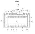
- FIG. 3 is a cross-sectional view showing a rechargeable battery in accordance with a second exemplary embodiment of the present invention.
- a rechargeable battery 120 in accordance with the second exemplary embodiment has the same structure as the rechargeable battery 110 in accordance with the first exemplary embodiment except for a cap assembly 40, and therefore repeated description of the same elements will be omitted.
- a cap assembly 40 in accordance with the present exemplary embodiment includes a second terminal 23 connected to a positive electrode 11.
- the second terminal 23 penetrating a cap plate 17 protrudes to the outside thereof and is electrically connected to the positive electrode 11 via a positive electrode lead tab 23a.
- a gasket 28 for sealing the second terminal 23 and the cap plate 17 is interposed therebetween, and a connection tab 29 for electrically connecting the cap plate 16 and the second terminal 23 is mounted on the second terminal 23.
- the connection tab 29 is inserted into the second terminal 23 and fixed between the second terminal 23 and the cap plate 17.
- the second terminal 23 is connected to the deformable plate 42 via the cap plate 17
- the first terminal 21 is connected to the deformable plate 42 via the first tab 41, and thus the positive electrode and the negative electrode are short-circuited with each other.
Abstract
Description
- The described technology relates generally to a rechargeable battery.
- A rechargeable battery can be repeatedly charged and discharged, unlike a primary battery that is incapable of being recharged. A low capacity rechargeable battery is generally used for a portable small electronic device, such as a mobile phone, a notebook computer, and a camcorder, and a large capacity rechargeable battery is widely used as a power source for driving a motor for a hybrid electric vehicle. Recently, a high power rechargeable battery using a non-aqueous electrolyte having a high energy density has been developed, and such a high power rechargeable battery is composed of a plurality of rechargeable batteries coupled in series so as to be used to drive a motor for an electric vehicle, for example, which requires high power. Moreover, a large capacity rechargeable battery is composed of a plurality of rechargeable batteries coupled in series, and the rechargeable battery may have a cylindrical or prismatic shape. The prismatic rechargeable battery includes an electrode assembly having an anode and a cathode with a separator interposed therebetween, a case having a space for receiving the electrode assembly, a cap plate closing and sealing the case and having a terminal hole through which a terminal is inserted, and the terminal electrically connected to the electrode assembly, inserted into the terminal hole, and protruding to the outside of the case. When excessive heat is generated in the rechargeable battery or when the internal pressure increases as an electrolyte solution is decomposed, the battery may explode or catch fire. Particularly, in the case of the prismatic battery, it is not easy to have a structure that cuts off or discharges current due to its specific characteristics of the terminal structure, compared to the cylindrical battery. The above information disclosed in this Background section is only for enhancement of understanding of the background of the described technology and therefore it may contain information that does not form the prior art that is already known in this country to a person of ordinary skill in the art.
- The described technology has been made in an effort to provide a rechargeable battery having an improved safety. An exemplary embodiment of the present invention provides a rechargeable battery comprising an electrode assembly having a first electrode, a second electrode, and a separator interposed between the first and the second electrodes, a case for mounting the electrode assembly therein, and a cap assembly comprising a cap plate for closing an opening of the case. The cap assembly comprises a deformable plate attached to the cap plate, the deformable plate being in communication with the inside of the battery and adapted to be deformed to short-circuit the first electrode and the second electrode.
- Advantageously, the safety of the battery is improved by providing a deformable plate which allows short-circuiting the battery.
- The deformable plate is preferably adapted to be deformed upon an increase of an internal pressure inside the case to short-circuit the first electrode and the second electrode. Additionally or alternatively, the deformable plate may be made of conductive material and/or may be electrically connected to the second electrode via the cap plate.
- According to the present invention, a short circuit occurs when the internal pressure of the rechargeable battery increases, and thus it is possible to prevent the rechargeable battery from exploding or catching fire.
- The cap assembly preferably further comprises a first tab located outside of the case and electrically connected to the first electrode, wherein the deformable plate is adapted to be deformed such that it contacts the first tab and thereby the first electrode. The first tab may be disposed on the cap plate on the outside of the battery.
- Advantageously, since the space in which the deformable plate contacts the first tab is separated from the space in which the electrolyte solution is located inside the battery, it is possible to prevent the electrolyte solution from catching fire due to flame or heat generated during the short circuit. Since a large current flows instantaneously when the short circuit occurs, the internal temperature of the battery may significantly increase if the short circuit region is located inside the case. However, according to the present invention, the first tab is located outside the case such that heat can be dissipated to the outside through the first tab, and thus it is possible to prevent heat from being excessively accumulated inside the case.
- The cap assembly preferably further comprises an insulating member such that the first tab is coupled to the cap plate with the insulating member interposed therebetween to electrically isolate the first tab from the cap plates. The insulating member may have a u-shape with an opening into which the first tab is inserted.
- The cap assembly preferably further comprises a first terminal protruding to the outside of the cap plate and electrically connected to the first electrode and the first tab. Additionally or alternatively, the cap assembly may further comprise a gasket interposed between the cap plate and the first terminal to insulate the cap plate and the first terminal from each other.
- In one embodiment, the first tab is attached to the first terminal by press-fitting the first tab between a region of the first terminal and the gasket.
- The cap plate preferably further comprises a hole covered by the deformable plate.
- The deformable plate is preferably adapted to be irreversibly deformed to short-circuit the first electrode and the second electrode such that the short-circuit is maintained after its establishment.
- Advantageously, the lifetime of the inventive deformable plate is prolonged with respect to a spring of the state of the art. The deformable plate of the present invention does not encounter a force and does not undergo an elastic deformation under a normal inner pressure of the battery at normal operation times of the battery, and thus the deformable plate can operate at a predetermined pressure even after the lapse of considerable time.
- The deformable plate may comprise a curved or an arc or a convex shaped deformable region, curved toward and protruding into the interior of the battery.
- The location in which the deformable plate contacts the first tab is preferably provided outside of the battery.
- Advantageously, the danger of electrolyte solution ignition upon establishment of the short is reduced.
- In one embodiment, the cap assembly further comprises a second terminal connected to the second electrode protruding to the outside of the battery, a gasket for sealing the cap plate in the region of the second terminal, and a connection tab for electrically connecting the second terminal and the cap plate such that the deformable plate contacts the second terminal via the cap plate and the deformable plate is adapted to contact the first terminal via the first tab.
- The cap assembly may further comprise a vent member having a predetermined breaking point.
- The battery is preferably a prismatic battery and/or the case has a cuboid shape.
-
-
FIG. 1 is a perspective view showing a rechargeable battery in accordance with a first exemplary embodiment of the present invention. -
FIG. 2 is a cross-sectional view taken along line II-II ofFIG. 1 . -
FIG. 3 is a cross-sectional view showing a rechargeable battery in accordance with a second exemplary embodiment of the present invention. - In the following description, a "deformable plate" includes all kinds of plates which are deformed by an increase in pressure, and the present invention does not particularly limit the shape. The deformable plate may also be called reversing plate since it may reverse its shape.
- Hereinafter, exemplary embodiments of the present invention will be described in detail with reference to the accompanying drawings such that those having ordinary skill in the art to which the present invention pertains may easily implement the technological concept of the present invention. However, the present invention may be implemented in various different ways and are not limited to the following exemplary embodiments. Like reference numerals designate like constituent elements throughout the specification.
-
FIG. 1 is a perspective view showing a rechargeable battery in accordance with a first exemplary embodiment of the present invention, andFIG. 2 is a cross-sectional view taken along line II-II ofFIG. 1 . - Referring to
FIGS. 1 and2 , arechargeable battery 110 in accordance with a first exemplary embodiment includes anelectrode assembly 10 formed by interposing aseparator 13 as an insulator between apositive electrode 11 and anegative electrode 12, acase 15 in which theelectrode assembly 10 is received, and acap assembly 20 connected to an opening of thecase 15. - The
rechargeable battery 110 in accordance with the first exemplary embodiment is a lithium ion secondary battery and will be described as an example of a prismatic battery. However, the present invention is not limited thereto, but may be applied to various types of batteries such as a lithium polymer battery or cylindrical battery. - Each of the
positive electrode 11 and thenegative electrode 12 includes a coated region in which an active material is coated on a current collector formed of a thin metal foil anduncoated regions negative electrode 12 may be referred to as a first electrode, thepositive electrode 11 may be referred to as a second electrode, and vice versa. A positiveuncoated region 11 a is formed on one end of thepositive electrode 11 along the longitudinal direction of thepositive electrode 11, and a negativeuncoated region 12a is formed on one end of thenegative electrode 12 opposite to the positiveuncoated region 11 a along the longitudinal direction of thenegative electrode 12. Thepositive electrode 11 and thenegative electrode 12 are spirally wound with theseparator 13 as an insulator interposed between thepositive electrode 11 and thenegative electrode 12. - However, the present invention is not limited thereto, but the
electrode assembly 10 may have a structure in which a plurality of positive electrodes and a plurality of negative electrodes each composed of a plurality of sheets are stacked with a separator interposed therebetween. - The
case 15 has a substantially cuboid shape having an opening side. Thecap assembly 20 includes acap plate 16 covering the opening of thecase 15, afirst terminal 21 protruding to the outside of thecap plate 16 and electrically connected to thenegative electrode 12, and a first short tab orfirst tab 41 electrically connected to thefirst terminal 21 and inserted into thecap plate 16 with aninsulating member 26 interposed therebetween. - The
cap plate 16 is formed of a thin plate, and avent member 25 having anotch 25a, which is broken by a predetermined internal pressure, is fixed to thecap plate 16. Preferably, thedeformable plate 42 is adapted to be deformed at a lower internal pressure than required for opening thevent member 25. In this way, it is ensured that after the battery is opened to its surrounding, the internal pressure or temperature is not able to further increase since the battery is short-circuited before. Thus, the safety of the battery is improved. However, since the deformation of thedeformable plate 42 according to the invention is preferably irreversible, thedeformable plate 42 may have a larger thickness than thevent member 25 but may be formed of a different material. - The
cap assembly 20 includes adeformable plate 42 short-circuiting thepositive electrode 11 and thenegative electrode 12, and thedeformable plate 42 short-circuits thefirst tab 41 and a second short tab or second tab when the internal pressure of therechargeable battery 110 increases. Thedeformable plate 42 of the first exemplary embodiment is fixedly mounted on thecap plate 16 such that thecap plate 16 serves as the second tab. - A
gasket 24 is interposed between thecap plate 16 and thefirst terminal 21 to insulate thecap plate 16 and the first terminal 21 from each other. Thefirst terminal 21 is electrically connected to thenegative electrode 12 via a negativeelectrode lead tab 21 a, and thecap plate 16 is electrically connected to thepositive electrode 11 via a positiveelectrode lead tab 22. - The
first terminal 21 penetrates thecap plate 16 and protrudes to the outside thereof, and thefirst tab 41 is inserted into thefirst terminal 21. In this state, the top of thefirst terminal 21 is spread by applying pressure, and thefirst tab 41 is fixed between thefirst terminal 21 and thegasket 24. That is, thefirst terminal 21 in accordance with the present exemplary embodiment is formed in a rivet shape. However, the present invention is not limited thereto, but thefirst terminal 21 and thefirst tab 41 may be fixed by fastening a nut to thefirst terminal 21. - The
first tab 41 has a substantially plate shape and is disposed on thecap plate 16. - The
deformable plate 42 is disposed below ashort hole 16a and has anadhesion region 42a adhered to the lower surface of thecap plate 16 by welding and adeformation region 42b formed inside theadhesion region 42a and protruding in an arc shape toward theelectrode assembly 10. Therefore, thedeformable plate 42 is electrically connected to thepositive electrode 11 through thecap plate 16. - When the internal pressure of the
rechargeable battery 110 increases, thedeformation region 42b protruding downwardly is reversed or deformed upwardly to contact theshort tab 41, and thereby thepositive electrode 11 and thenegative electrode 12 are short-circuited with each other. - As such, according to the first exemplary embodiment, when the internal pressure of the
rechargeable battery 110 excessively increases as the temperature increases or as an electrolyte solution is decomposed, thedeformation region 42b causes a short circuit, thus preventing therechargeable battery 110 from exploding or catching fire. Since the pressure at which thedeformable plate 42 is deformed can be easily adjusted by changing its thickness and shape, it is possible to accurately set the pressure that causes a short circuit. - Particularly, since the space in which the
deformable plate 42 contacts thefirst tab 41 is separated from the space in which the electrolyte solution is located, it is possible to prevent the electrolyte solution from catching fire due to flame or heat generated during the short circuit. Since a large current flows instantaneously when the short circuit occurs, the internal temperature of the battery may significantly increase if the short circuit region is located in thecase 15. However, according to the present exemplary embodiment, thefirst tab 41 is located outside thecase 15 such that heat can be dissipated to the outside through thefirst tab 41, and thus it is possible to prevent heat from being excessively accumulated inside thecase 15. - Moreover, since a pressing force is continuously applied to an elastic member such as a spring at all times, its elasticity may be reduced or completely eliminated if it is used for a long time. In order to ensure safety with respect to the cycle-life of the
rechargeable battery 110, it is important that the elastic member does not lose its elasticity during the use of therechargeable battery 110 but operates at a predetermined pressure. However, the elastic member such as a spring may lose its elasticity during the use of therechargeable battery 110 and thus may not operate at the predetermined pressure. According to the present exemplary embodiment, thedeformable plate 42 does not undergo an elastic deformation under a normal inner pressure at ordinary times, and thus thedeformable plate 42 can operate at the predetermined pressure even after the lapse of considerable time. -
FIG. 3 is a cross-sectional view showing a rechargeable battery in accordance with a second exemplary embodiment of the present invention. - Referring to
FIG. 3 , a rechargeable battery 120 in accordance with the second exemplary embodiment has the same structure as therechargeable battery 110 in accordance with the first exemplary embodiment except for acap assembly 40, and therefore repeated description of the same elements will be omitted. - As shown in
FIG. 3 , acap assembly 40 in accordance with the present exemplary embodiment includes asecond terminal 23 connected to apositive electrode 11. Thesecond terminal 23 penetrating acap plate 17 protrudes to the outside thereof and is electrically connected to thepositive electrode 11 via a positiveelectrode lead tab 23a. - Moreover, a
gasket 28 for sealing thesecond terminal 23 and thecap plate 17 is interposed therebetween, and aconnection tab 29 for electrically connecting thecap plate 16 and thesecond terminal 23 is mounted on thesecond terminal 23. Theconnection tab 29 is inserted into thesecond terminal 23 and fixed between thesecond terminal 23 and thecap plate 17. - When a
deformable plate 42 is deformed by an increase in the internal pressure of the rechargeable battery 120, thesecond terminal 23 is connected to thedeformable plate 42 via thecap plate 17, thefirst terminal 21 is connected to thedeformable plate 42 via thefirst tab 41, and thus the positive electrode and the negative electrode are short-circuited with each other. - While this invention has been described in connection with what is presently considered to be practical exemplary embodiments, it is to be understood that the invention is not limited to the disclosed embodiments, but, on the contrary, is intended to cover various modifications and equivalent arrangements included within the scope of the appended claims.
Claims (15)
- A rechargeable battery (110, 140) comprising:an electrode assembly (10) having a first electrode (12), a second electrode (11), and a separator (13) interposed between the first and the second electrodes (12, 11);a case (15) for mounting the electrode assembly (10) therein;a cap assembly (20, 40) comprising a cap plate (16, 17) for closing an opening of the case (15);characterized in thatthe cap assembly (20, 40) comprises:a deformable plate (42) attached to the cap plate (16, 17), the deformable plate (42) being in communication with the inside of the battery (110, 140) and adapted to be deformed to short-circuit the first electrode (12) and the second electrode (11).
- Rechargeable battery (110, 140) according to claim 1, wherein the deformable plate (16):is adapted to be deformed upon an increase of an internal pressure inside the case (15) to short-circuit the first electrode (12) and the second electrode (11); and/or
is made of conductive material; and/or
is electrically connected to the second electrode (11) via the cap plate (16, 17). - Rechargeable battery (110, 140) according to claim 1 or 2, wherein the cap assembly (20, 40) further comprises a first tab (41) located outside of the case (15) and electrically connected to the first electrode (12), wherein the deformable plate (16) is adapted to be deformed such that it contacts the first tab (41) and thereby the first electrode (12).
- Rechargeable battery (110, 140) according to claim 3, wherein the first tab (41) is disposed on the cap plate (16, 17) on the outside of the battery (110, 140).
- Rechargeable battery (110, 140) according to claim 3 or 4, wherein the cap assembly (20, 40) further comprises an insulating member (26) such that the first tab (41) is coupled to the cap plate (16, 17) with the insulating member (26) interposed therebetween to electrically isolate the first tab (41) from the cap plate (16, 17).
- Rechargeable battery (110, 140) according to claim 5, wherein the insulating member (26) has a u-shape with an opening into which the first tab (41) is inserted.
- Rechargeable battery (110, 140) according to any of claims 3 to 6, wherein the cap assembly (20, 40) further comprises:a first terminal (21) protruding to the outside of the cap plate (16, 17) and electrically connected to the first electrode (12) and the first tab (41); and/ora gasket (24) interposed between the cap plate (16, 17) and the first terminal (21) to insulate the cap plate (16, 17) and the first terminal (21) from each other.
- Rechargeable battery (110, 140) according to claim 7, wherein the first tab (41) is attached to the first terminal (21) by press-fitting the first tab (41) between a region of the first terminal (21) and the gasket (24).
- Rechargeable battery (110, 140) according to any of the previous claims, wherein the cap plate (16, 17) further comprises a hole (16a, 17a) covered by the deformable plate (42).
- Rechargeable battery (110, 140) according to any of the previous claims, wherein the deformable plate (42) is adapted to be irreversibly deformed to short-circuit the first electrode (12) and the second electrode (11) such that the short-circuit is maintained after its establishment.
- Rechargeable battery (110, 140) according to any of the previous claims, wherein the deformable plate (42) comprises a curved or an arc or a convex shaped deformable region, curved toward and protruding into the interior of the battery (110, 140).
- Rechargeable battery (110, 140) according to any of the previous claims, wherein the location in which the deformable plate (42) contacts the first tab (41) is provided outside of the battery (110, 140).
- Rechargeable battery (110, 140) according to any of the previous claims, wherein the cap assembly (40) comprises
a second terminal (23) connected to the second electrode (11) protruding to the outside of the battery (110, 140); and
a gasket (28) for sealing the cap plate (16, 17) in the region of the second terminal (23), and a connection tab (29) for electrically connecting the second terminal (23) and the cap plate (17) such that the deformable plate (42) contacts the second terminal (23) via the cap plate (17) and the deformable plate (42) is adapted to contact the first terminal (21) via the first tab (41). - Rechargeable battery (110, 140) according to any of the previous claims, wherein the cap assembly (20, 40) further comprises a vent member (25) having a predetermined breaking point (25a).
- Rechargeable battery (110, 140) according to any of the previous claims, wherein the battery (110, 140) is a prismatic battery and/or the case (15) has a cuboid shape.
Applications Claiming Priority (2)
| Application Number | Priority Date | Filing Date | Title |
|---|---|---|---|
| US22439209P | 2009-07-09 | 2009-07-09 | |
| US12/626,582 US9246140B2 (en) | 2009-07-09 | 2009-11-25 | Rechargeable battery with a cap assembly having a first tab located outside of the case |
Publications (2)
| Publication Number | Publication Date |
|---|---|
| EP2273587A1 true EP2273587A1 (en) | 2011-01-12 |
| EP2273587B1 EP2273587B1 (en) | 2013-05-29 |
Family
ID=43030607
Family Applications (1)
| Application Number | Title | Priority Date | Filing Date |
|---|---|---|---|
| EP10167890.2A Active EP2273587B1 (en) | 2009-07-09 | 2010-06-30 | Rechargeable battery |
Country Status (5)
| Country | Link |
|---|---|
| US (1) | US9246140B2 (en) |
| EP (1) | EP2273587B1 (en) |
| JP (1) | JP5399990B2 (en) |
| KR (1) | KR101093691B1 (en) |
| CN (1) | CN101950812A (en) |
Cited By (6)
| Publication number | Priority date | Publication date | Assignee | Title |
|---|---|---|---|---|
| EP2403036A1 (en) * | 2010-06-30 | 2012-01-04 | SB LiMotive Co., Ltd. | Rechargeable battery |
| EP2432042A1 (en) * | 2010-09-17 | 2012-03-21 | SB LiMotive Co., Ltd. | Rechargeable battery |
| US8617737B2 (en) | 2010-01-26 | 2013-12-31 | Samsung Sdi Co., Ltd. | Rechargeable battery |
| DE102012015816A1 (en) * | 2012-08-10 | 2014-02-13 | Dr. Ing. H.C. F. Porsche Ag | Automobile battery |
| EP2874196A1 (en) * | 2013-11-15 | 2015-05-20 | Samsung SDI Co., Ltd. | Connection and insulation elements inside of a secondary battery |
| EP2897193A1 (en) * | 2014-01-20 | 2015-07-22 | Samsung SDI Co., Ltd. | Rechargeable battery pack |
Families Citing this family (88)
| Publication number | Priority date | Publication date | Assignee | Title |
|---|---|---|---|---|
| US9246140B2 (en) | 2009-07-09 | 2016-01-26 | Samsung Sdi Co., Ltd. | Rechargeable battery with a cap assembly having a first tab located outside of the case |
| US8877361B2 (en) * | 2009-09-01 | 2014-11-04 | Samsung Sdi Co., Ltd. | Rechargeable battery |
| US8440336B2 (en) * | 2009-12-08 | 2013-05-14 | Samsung Sdi Co., Ltd. | Rechargeable battery with short circuit member |
| US8632911B2 (en) * | 2010-01-15 | 2014-01-21 | Samsung Sdi Co., Ltd. | Rechargeable battery |
| KR101223519B1 (en) * | 2010-11-05 | 2013-01-17 | 로베르트 보쉬 게엠베하 | Battery module |
| US9478774B2 (en) * | 2010-12-02 | 2016-10-25 | Samsung Sdi Co., Ltd. | Rechargeable battery |
| KR101222286B1 (en) | 2011-01-13 | 2013-01-15 | 로베르트 보쉬 게엠베하 | Secondary battery |
| KR101222376B1 (en) | 2011-01-14 | 2013-01-15 | 로베르트 보쉬 게엠베하 | Secondary battery |
| KR101233470B1 (en) * | 2011-01-25 | 2013-02-15 | 로베르트 보쉬 게엠베하 | Rechargeable battery |
| KR101222306B1 (en) * | 2011-01-31 | 2013-01-16 | 로베르트 보쉬 게엠베하 | Rechargeable battery |
| KR101175020B1 (en) * | 2011-02-08 | 2012-08-17 | 에스비리모티브 주식회사 | Rechargeable battery |
| US9023497B2 (en) * | 2011-02-18 | 2015-05-05 | Samsung Sdi Co., Ltd. | Secondary battery |
| US8753765B2 (en) * | 2011-03-14 | 2014-06-17 | Samsung Sdi Co., Ltd. | Secondary battery |
| US9537121B2 (en) * | 2011-03-18 | 2017-01-03 | Samsung Sdi Co., Ltd. | Secondary battery and secondary battery pack having a flexible collecting tab extending through a cap plate |
| KR101243475B1 (en) * | 2011-03-30 | 2013-03-13 | 로베르트 보쉬 게엠베하 | Secondary battery including short-member |
| KR101254886B1 (en) | 2011-04-04 | 2013-04-15 | 로베르트 보쉬 게엠베하 | Secondary battery |
| KR101222232B1 (en) | 2011-04-07 | 2013-01-16 | 로베르트 보쉬 게엠베하 | Secondary battery |
| KR101254871B1 (en) * | 2011-04-18 | 2013-04-15 | 로베르트 보쉬 게엠베하 | Secondary battery |
| JP5741201B2 (en) * | 2011-05-11 | 2015-07-01 | トヨタ自動車株式会社 | Sealed battery, assembled battery, and method for manufacturing sealed battery |
| KR101265202B1 (en) | 2011-06-08 | 2013-05-27 | 로베르트 보쉬 게엠베하 | Rechargeable battery |
| US8642196B2 (en) * | 2011-06-08 | 2014-02-04 | Samsung Sdi Co., Ltd. | Rechargeable battery |
| US9023498B2 (en) * | 2011-07-07 | 2015-05-05 | Samsung Sdi Co., Ltd. | Rechargeable battery |
| KR101274806B1 (en) | 2011-07-26 | 2013-06-13 | 로베르트 보쉬 게엠베하 | Rechargeable battery |
| DE112011105182B4 (en) * | 2011-07-27 | 2017-11-23 | Toyota Jidosha Kabushiki Kaisha | Sealed cell |
| KR101274909B1 (en) * | 2011-07-29 | 2013-06-17 | 로베르트 보쉬 게엠베하 | Rechargeable battery |
| US9634299B2 (en) * | 2011-09-06 | 2017-04-25 | Samsung Sdi Co., Ltd. | Rechargeable battery |
| KR20130039178A (en) * | 2011-10-11 | 2013-04-19 | 삼성에스디아이 주식회사 | Rechargeable battery |
| KR101683210B1 (en) | 2011-11-17 | 2016-12-07 | 삼성에스디아이 주식회사 | Rechargeable battery |
| KR101695992B1 (en) * | 2011-11-30 | 2017-01-13 | 삼성에스디아이 주식회사 | Secondary battery |
| US9172079B2 (en) * | 2012-02-01 | 2015-10-27 | Samsung Sdi Co., Ltd. | Rechargeable battery |
| JP5945989B2 (en) * | 2012-07-19 | 2016-07-05 | 株式会社豊田自動織機 | Power storage device with current interrupt device |
| JP5911772B2 (en) | 2012-08-09 | 2016-04-27 | 三洋電機株式会社 | Non-aqueous electrolyte secondary battery and manufacturing method thereof |
| KR101683199B1 (en) * | 2012-11-20 | 2016-12-06 | 삼성에스디아이 주식회사 | Rechargeable battery |
| KR20140064487A (en) * | 2012-11-20 | 2014-05-28 | 삼성에스디아이 주식회사 | Rechargeable battery module |
| KR101666258B1 (en) * | 2013-01-23 | 2016-10-13 | 삼성에스디아이 주식회사 | Rechargeable battery |
| KR101675618B1 (en) | 2013-02-20 | 2016-11-11 | 삼성에스디아이 주식회사 | Secondary battery |
| KR102050484B1 (en) | 2013-03-04 | 2019-12-02 | 삼성디스플레이 주식회사 | Anthracene derivatives and organic light emitting diodes comprising the derivatives |
| DE102013204341A1 (en) * | 2013-03-13 | 2014-09-18 | Robert Bosch Gmbh | Security element for battery cell |
| KR20140124247A (en) * | 2013-04-16 | 2014-10-24 | 삼성에스디아이 주식회사 | Rechargeable battery |
| KR102107106B1 (en) | 2013-05-09 | 2020-05-07 | 삼성디스플레이 주식회사 | Styryl-based compound and organic light emitting diode comprising the same |
| US10109889B2 (en) * | 2013-07-01 | 2018-10-23 | Sanyo Electric Co., Ltd. | Non-aqueous electrolyte secondary battery |
| KR101744090B1 (en) * | 2013-09-06 | 2017-06-07 | 삼성에스디아이 주식회사 | Rechargeable battery having short member |
| KR20150041518A (en) * | 2013-10-08 | 2015-04-16 | 삼성에스디아이 주식회사 | Secondary battery |
| KR101775545B1 (en) * | 2013-10-08 | 2017-09-06 | 삼성에스디아이 주식회사 | Rechargeable battery having short protrusion |
| US10062850B2 (en) | 2013-12-12 | 2018-08-28 | Samsung Display Co., Ltd. | Amine-based compounds and organic light-emitting devices comprising the same |
| DE102014200202A1 (en) * | 2014-01-09 | 2015-07-09 | Robert Bosch Gmbh | Battery cell with overvoltage protection device |
| KR102272264B1 (en) | 2014-01-20 | 2021-07-02 | 삼성에스디아이 주식회사 | Battery module having short connecting part |
| KR102154331B1 (en) * | 2014-02-14 | 2020-09-09 | 삼성에스디아이 주식회사 | Secondary Battery |
| KR102211364B1 (en) * | 2014-04-07 | 2021-02-03 | 삼성에스디아이 주식회사 | Secondary battery |
| KR102210885B1 (en) * | 2014-05-15 | 2021-02-02 | 삼성에스디아이 주식회사 | Secondary battery and manufacturing method for the same |
| KR20150132795A (en) | 2014-05-16 | 2015-11-26 | 삼성디스플레이 주식회사 | Organic light emitting device |
| KR102327086B1 (en) | 2014-06-11 | 2021-11-17 | 삼성디스플레이 주식회사 | Organic light-emitting devices |
| US9985271B2 (en) * | 2014-07-31 | 2018-05-29 | Johnson Controls Technology Company | Overcharge protection device for a battery module |
| KR102343145B1 (en) | 2015-01-12 | 2021-12-27 | 삼성디스플레이 주식회사 | Condensed compound and organic light-emitting device comprising the same |
| KR102299244B1 (en) * | 2015-01-14 | 2021-09-07 | 삼성에스디아이 주식회사 | Rechargeable battery and pack of the same |
| KR102340114B1 (en) * | 2015-02-27 | 2021-12-15 | 삼성에스디아이 주식회사 | Rechargeable battery |
| KR102358434B1 (en) | 2015-04-17 | 2022-02-04 | 삼성에스디아이 주식회사 | Secondary battery |
| KR102391252B1 (en) * | 2015-04-17 | 2022-04-26 | 삼성에스디아이 주식회사 | Rechargeable battery |
| WO2016197375A1 (en) * | 2015-06-11 | 2016-12-15 | 宁德时代新能源科技股份有限公司 | Power battery cap structure and power battery |
| EP3390134A4 (en) | 2015-12-14 | 2019-05-15 | Cadenza Innovation, Inc. | Low profile pressure disconnect device for lithium ion batteries |
| JP6863710B2 (en) * | 2015-12-28 | 2021-04-21 | パナソニック株式会社 | Secondary battery |
| JP6812651B2 (en) * | 2016-03-25 | 2021-01-13 | 株式会社豊田自動織機 | Power storage device |
| KR102612060B1 (en) * | 2016-04-26 | 2023-12-07 | 삼성에스디아이 주식회사 | Rechargeable battery having membrane |
| CN105870375B (en) * | 2016-06-07 | 2018-07-10 | 宁德时代新能源科技股份有限公司 | Power battery top cap and power battery |
| JP6674631B2 (en) | 2016-06-23 | 2020-04-01 | トヨタ自動車株式会社 | Lithium ion secondary battery |
| JP6996505B2 (en) * | 2016-06-29 | 2022-01-17 | 三洋電機株式会社 | Secondary battery |
| JP6729137B2 (en) | 2016-07-28 | 2020-07-22 | 三洋電機株式会社 | Secondary battery, manufacturing method thereof, and assembled battery using the same |
| WO2018048075A1 (en) * | 2016-09-06 | 2018-03-15 | 삼성에스디아이(주) | Secondary battery |
| KR102201278B1 (en) * | 2016-09-19 | 2021-01-08 | 삼성에스디아이 주식회사 | Rechargeable battery |
| KR102422513B1 (en) * | 2016-10-24 | 2022-07-20 | 삼성에스디아이 주식회사 | Secondary Battery |
| CN106450052A (en) * | 2016-11-15 | 2017-02-22 | 宁德时代新能源科技股份有限公司 | Secondary battery |
| CN106410074B (en) * | 2016-11-15 | 2019-04-05 | 宁德时代新能源科技股份有限公司 | Secondary battery |
| CN109792009B (en) * | 2016-11-15 | 2022-01-21 | 宁德时代新能源科技股份有限公司 | Secondary battery |
| JP6519575B2 (en) | 2016-12-07 | 2019-05-29 | トヨタ自動車株式会社 | Lithium ion secondary battery |
| EP3336932A1 (en) * | 2016-12-14 | 2018-06-20 | Lithium Energy and Power GmbH & Co. KG | Battery with enhanced discharging device |
| JP6760045B2 (en) | 2016-12-21 | 2020-09-23 | 三洋電機株式会社 | Square secondary battery and its manufacturing method |
| JP6519577B2 (en) | 2016-12-22 | 2019-05-29 | トヨタ自動車株式会社 | Lithium ion secondary battery |
| KR20180119375A (en) * | 2017-04-25 | 2018-11-02 | 삼성에스디아이 주식회사 | Secondary Battery |
| JP6859852B2 (en) * | 2017-05-31 | 2021-04-14 | 三洋電機株式会社 | Square secondary batteries, assembled batteries and vehicles using them |
| JP6859851B2 (en) | 2017-05-31 | 2021-04-14 | 三洋電機株式会社 | Square secondary batteries, assembled batteries and vehicles using them |
| KR102449106B1 (en) | 2017-07-10 | 2022-09-29 | 삼성에스디아이 주식회사 | Secondary battery capable of internal and external pressure balancing |
| CN113451713B (en) * | 2017-08-30 | 2024-03-19 | 宁德时代新能源科技股份有限公司 | Secondary battery and battery module |
| KR102425219B1 (en) * | 2017-09-07 | 2022-07-26 | 삼성에스디아이 주식회사 | Secondary Battery |
| JP7098901B2 (en) | 2017-09-29 | 2022-07-12 | 三洋電機株式会社 | Secondary battery and its manufacturing method |
| CN107665970A (en) * | 2017-11-16 | 2018-02-06 | 北京国能电池科技有限公司 | Over-charging of battery safety guard and lithium ion battery |
| KR102571489B1 (en) | 2018-03-21 | 2023-08-28 | 삼성에스디아이 주식회사 | Secondary Battery |
| JP7248812B2 (en) * | 2019-10-31 | 2023-03-29 | 寧徳時代新能源科技股▲分▼有限公司 | Battery module, battery pack, device and failure handling method |
| CN116014317B (en) * | 2023-02-09 | 2023-06-27 | 深圳海润新能源科技有限公司 | End cover assembly, energy storage device and electric equipment |
Citations (2)
| Publication number | Priority date | Publication date | Assignee | Title |
|---|---|---|---|---|
| JP2004319463A (en) * | 2003-03-28 | 2004-11-11 | Matsushita Electric Ind Co Ltd | Secondary battery |
| EP1717886A2 (en) * | 2005-04-25 | 2006-11-02 | Samsung SDI Co., Ltd. | Can type lithium secondary battery |
Family Cites Families (113)
| Publication number | Priority date | Publication date | Assignee | Title |
|---|---|---|---|---|
| US4209571A (en) | 1975-08-28 | 1980-06-24 | Gte Laboratories Incorporated | Primary electrochemical cell |
| US4879187A (en) | 1987-10-22 | 1989-11-07 | Eveready Battery Company | Battery terminal fuse |
| US5143860A (en) | 1987-12-23 | 1992-09-01 | Texas Instruments Incorporated | High density EPROM fabricaiton method having sidewall floating gates |
| US4945014A (en) * | 1988-02-10 | 1990-07-31 | Mitsubishi Petrochemical Co., Ltd. | Secondary battery |
| JPH0562664A (en) | 1991-09-02 | 1993-03-12 | Matsushita Electric Ind Co Ltd | Explosion proof type nonaqueous secondary battery |
| JPH05251290A (en) | 1992-03-07 | 1993-09-28 | Hitachi Aic Inc | Cased capacitor |
| JPH05275088A (en) | 1992-03-27 | 1993-10-22 | Yuasa Corp | Laminated thin type battery |
| JP3232767B2 (en) | 1993-03-31 | 2001-11-26 | 株式会社デンソー | Chemical battery with safety mechanism |
| US5523178A (en) | 1992-12-14 | 1996-06-04 | Nippondenso Co., Ltd. | Chemical cell |
| JPH0737572A (en) | 1993-07-22 | 1995-02-07 | Japan Storage Battery Co Ltd | Lithium battery |
| JP3573293B2 (en) | 1993-11-24 | 2004-10-06 | 日本電池株式会社 | battery |
| JPH0850920A (en) | 1994-08-08 | 1996-02-20 | Toyo Takasago Kandenchi Kk | Square type lithium secondary cell |
| US5707756A (en) | 1994-11-29 | 1998-01-13 | Fuji Photo Film Co., Ltd. | Non-aqueous secondary battery |
| JPH08185850A (en) | 1994-12-27 | 1996-07-16 | Sony Corp | Lithium ion secondary battery |
| JPH09106804A (en) | 1995-10-09 | 1997-04-22 | Wako Denshi Kk | Safety apparatus for battery |
| JPH1074500A (en) * | 1996-08-30 | 1998-03-17 | Sanyo Electric Co Ltd | Sealed battery and its manufacture |
| TW332342B (en) | 1996-11-11 | 1998-05-21 | Mos Electronics Taiwan Inc | Structure and fabrication method of split-gate flash memory |
| JPH10188946A (en) | 1996-12-20 | 1998-07-21 | Toyo Takasago Kandenchi Kk | Rectangular battery with inner short circuit protecting device |
| JP3464750B2 (en) | 1997-01-21 | 2003-11-10 | 東芝電池株式会社 | Lithium secondary battery |
| US6069551A (en) | 1997-05-02 | 2000-05-30 | Therm-O-Disc, Incorporated | Thermal switch assembly |
| US5800937A (en) | 1997-05-02 | 1998-09-01 | Motorola, Inc. | Current interrupt device for secondary batteries |
| JPH10326610A (en) | 1997-05-27 | 1998-12-08 | Hitachi Ltd | Non-aqueous electrolyte secondary battery |
| JPH117931A (en) | 1997-06-18 | 1999-01-12 | Hitachi Ltd | Secondary battery |
| JPH1140203A (en) | 1997-07-14 | 1999-02-12 | Hitachi Ltd | Secondary battery |
| JPH11191436A (en) | 1997-12-26 | 1999-07-13 | Hitachi Ltd | Capacitor protector |
| KR200283452Y1 (en) | 1997-12-30 | 2002-09-19 | 삼성에스디아이 주식회사 | Non-Aqueous Solution Secondary Battery |
| TW502467B (en) | 1998-03-18 | 2002-09-11 | Toshiba Battery | Battery, lead member for battery connection, and battery pack using the same |
| JP4303801B2 (en) | 1998-03-25 | 2009-07-29 | ワコー電子株式会社 | Secondary battery safety device |
| JPH11307076A (en) | 1998-04-24 | 1999-11-05 | Sony Corp | Secondary battery |
| JP3497380B2 (en) | 1998-06-02 | 2004-02-16 | 日本碍子株式会社 | Lithium secondary battery |
| KR100270958B1 (en) | 1998-07-10 | 2000-11-01 | 윤종용 | Non-volatile semiconductor device and method for fabricating the same |
| DE19837909C2 (en) | 1998-08-20 | 2001-05-17 | Implex Hear Tech Ag | Protection device for a multi-rechargeable electrochemical battery |
| JP2000082457A (en) | 1998-09-04 | 2000-03-21 | Toyo Kohan Co Ltd | Electric/electronic equipment and part safeguard, sealed battery safeguard using it and sealed battery using it |
| JP2000182598A (en) | 1998-12-16 | 2000-06-30 | Hitachi Ltd | Nonaqueous electrolyte secondary battery and electrothermal relay for battery |
| KR100358062B1 (en) | 1998-12-30 | 2003-01-24 | 주식회사 하이닉스반도체 | Flash memory cell and method for manufacturing the same |
| JP3693844B2 (en) | 1999-03-01 | 2005-09-14 | アルプス電気株式会社 | Battery-sensitive piezoelectric path blocking mechanism |
| FR2796205B1 (en) | 1999-07-08 | 2001-10-05 | Cit Alcatel | WATERPROOF ELECTROCHEMICAL ACCUMULATOR COMPRISING AN ALUMINUM RECOVERY DEVICE |
| KR100358224B1 (en) | 1999-07-31 | 2002-10-25 | 주식회사 엘지화학 | Lithium secondary battery |
| US6342826B1 (en) * | 1999-08-11 | 2002-01-29 | Therm-O-Disc, Incorporated | Pressure and temperature responsive switch assembly |
| US6525371B2 (en) | 1999-09-22 | 2003-02-25 | International Business Machines Corporation | Self-aligned non-volatile random access memory cell and process to make the same |
| KR100349908B1 (en) | 1999-12-15 | 2002-08-22 | 삼성에스디아이 주식회사 | Prismatic type sealed battery |
| JP2001202946A (en) | 2000-01-18 | 2001-07-27 | Nec Corp | Secondary battery with nonaqueous electrolytic solution |
| JP2001357834A (en) | 2000-06-16 | 2001-12-26 | Japan Storage Battery Co Ltd | Battery |
| JP2002216743A (en) | 2001-01-19 | 2002-08-02 | Alps Electric Co Ltd | Pressure cutoff sensor for battery |
| FR2821983B1 (en) | 2001-03-07 | 2003-08-15 | Schneider Electric Ind Sa | CONNECTION DEVICE FOR ELECTRIC BATTERY |
| TW480680B (en) | 2001-04-03 | 2002-03-21 | Nanya Technology Corp | Method for producing self-aligned separated gate-type flash memory cell |
| US6730430B2 (en) | 2001-07-09 | 2004-05-04 | Nan Ya Plastics Corporation | Explosion-proof safety structure for column shape lithium battery |
| JP4645001B2 (en) | 2001-07-11 | 2011-03-09 | 株式会社Gsユアサ | battery |
| CN1252843C (en) | 2001-07-11 | 2006-04-19 | 能元科技股份有限公司 | Safety protection structure of square cell |
| JP4154136B2 (en) | 2001-08-06 | 2008-09-24 | 松下電器産業株式会社 | Square sealed battery |
| WO2003015195A1 (en) | 2001-08-07 | 2003-02-20 | Matsushita Electric Industrial Co., Ltd. | Non-aqueous electrolytic secondary battery |
| JP2003051304A (en) | 2001-08-07 | 2003-02-21 | Matsushita Electric Ind Co Ltd | Nonaqueous electrolyte secondary battery |
| KR100420146B1 (en) | 2001-10-18 | 2004-03-02 | 삼성에스디아이 주식회사 | Secondary battery mounting thermal protector |
| JP2003197178A (en) | 2001-12-25 | 2003-07-11 | Mitsubishi Heavy Ind Ltd | Secondary battery |
| JP2003223886A (en) | 2002-01-30 | 2003-08-08 | Sanyo Gs Soft Energy Co Ltd | Battery |
| JP2003234055A (en) | 2002-02-12 | 2003-08-22 | Texas Instr Japan Ltd | Overvoltage protector and battery protective system using the same |
| JP4629952B2 (en) | 2002-02-13 | 2011-02-09 | パナソニック株式会社 | Manufacturing method of secondary battery |
| JP4967216B2 (en) | 2003-12-05 | 2012-07-04 | 株式会社Gsユアサ | Non-aqueous electrolyte battery |
| JP2004022477A (en) | 2002-06-20 | 2004-01-22 | Matsushita Electric Ind Co Ltd | Battery |
| JP2004071265A (en) | 2002-08-05 | 2004-03-04 | Sanyo Electric Co Ltd | Battery |
| JP2004087194A (en) | 2002-08-23 | 2004-03-18 | Nok Corp | Sealing plate |
| KR100477750B1 (en) | 2002-09-23 | 2005-03-18 | 삼성에스디아이 주식회사 | Electorde assembly for lithium ion cell and lithium ion cell using the same |
| JP2004273139A (en) | 2003-03-05 | 2004-09-30 | Canon Inc | Lithium secondary battery |
| JP4259890B2 (en) | 2003-03-07 | 2009-04-30 | 三洋電機株式会社 | Sealed storage battery |
| JP2005032477A (en) | 2003-07-08 | 2005-02-03 | Toyota Motor Corp | Battery and automobile mounting it |
| KR100516772B1 (en) | 2003-08-22 | 2005-09-22 | 삼성에스디아이 주식회사 | Secondary Battery having a Tap in Short Part of Can |
| JP4953551B2 (en) | 2003-10-31 | 2012-06-13 | 三洋電機株式会社 | Sealed battery |
| US7029968B2 (en) | 2003-12-05 | 2006-04-18 | Taiwan Semiconductor Manufacturing Company, Ltd. | Method of forming a PIP capacitor |
| US7315056B2 (en) | 2004-06-07 | 2008-01-01 | Silicon Storage Technology, Inc. | Semiconductor memory array of floating gate memory cells with program/erase and select gates |
| JP2006012602A (en) | 2004-06-25 | 2006-01-12 | Japan Storage Battery Co Ltd | Storage battery |
| KR100619631B1 (en) | 2004-08-31 | 2006-09-12 | 주식회사 엘지화학 | Improved Lithium Secondary Battery |
| KR100624919B1 (en) | 2004-09-22 | 2006-09-15 | 삼성에스디아이 주식회사 | Secondary Battery |
| KR20060039955A (en) | 2004-11-02 | 2006-05-10 | 유니썸테크놀로지 주식회사 | Safety apparatus for battery |
| KR20070084079A (en) | 2004-11-08 | 2007-08-24 | 소니 가부시끼 가이샤 | Battery and center pin |
| KR100614377B1 (en) * | 2004-11-15 | 2006-08-21 | 삼성에스디아이 주식회사 | Secondary Battery |
| CN1655389A (en) | 2005-03-04 | 2005-08-17 | 北京中信国安盟固利新材料技术研究院有限公司 | High capacity lithium ion secondary battery with metal case |
| US7157372B1 (en) | 2005-06-14 | 2007-01-02 | Cubic Wafer Inc. | Coaxial through chip connection |
| US7364970B2 (en) | 2005-09-30 | 2008-04-29 | Freescale Semiconductor, Inc. | Method of making a multi-bit non-volatile memory (NVM) cell and structure |
| KR100693115B1 (en) | 2005-11-08 | 2007-03-12 | 주식회사 비츠로셀 | Cathode lead having function as a fuse |
| KR100878702B1 (en) | 2005-11-30 | 2009-01-14 | 주식회사 엘지화학 | Safety Device for Secondary Battery and Battery Pack Employed with the Same |
| JP4848860B2 (en) | 2006-01-13 | 2011-12-28 | ソニー株式会社 | battery |
| KR100878701B1 (en) | 2006-03-13 | 2009-01-14 | 주식회사 엘지화학 | High Rate Charging and Discharging Cylindrical Secondary Battery |
| KR100906253B1 (en) | 2006-05-01 | 2009-07-07 | 주식회사 엘지화학 | Secondary Battery Having Electrode With Self Cutting Part To Be Destructed On Application Of Over-Current |
| JP2008027668A (en) | 2006-07-19 | 2008-02-07 | Sony Corp | Battery |
| KR20080025437A (en) | 2006-09-18 | 2008-03-21 | 주식회사 엘지화학 | Secondary battery capable of adjusting position of electrode terminal and having improved safety |
| KR100880321B1 (en) | 2006-12-14 | 2009-01-28 | 삼성에스디아이 주식회사 | Secondary battery |
| JP4609432B2 (en) | 2007-01-19 | 2011-01-12 | 住友電気工業株式会社 | Lead terminal for power storage device with fuse and non-aqueous electrolyte power storage device |
| JP5271498B2 (en) | 2007-01-26 | 2013-08-21 | 三菱重工業株式会社 | Lithium secondary battery and battery pack |
| JP2008218132A (en) | 2007-03-02 | 2008-09-18 | Matsushita Electric Ind Co Ltd | Sealed battery |
| KR100870349B1 (en) | 2007-03-16 | 2008-11-25 | 삼성에스디아이 주식회사 | Terminal of ProtectCircuit Module and Secondary Battery of using the same |
| KR100922352B1 (en) | 2007-10-02 | 2009-10-21 | 삼성에스디아이 주식회사 | Rechargeable battery |
| KR100963994B1 (en) | 2008-03-12 | 2010-06-15 | 엔피텍주식회사 | inner battery pack and manufacturing |
| JP5314350B2 (en) | 2008-07-25 | 2013-10-16 | 三菱重工業株式会社 | Battery pack container and battery pack |
| JP2010033949A (en) | 2008-07-30 | 2010-02-12 | Panasonic Corp | Battery |
| JP5288973B2 (en) | 2008-09-29 | 2013-09-11 | 三洋電機株式会社 | Rectangular secondary battery and battery module |
| JP5418809B2 (en) | 2008-10-16 | 2014-02-19 | 株式会社Gsユアサ | Battery and manufacturing method thereof |
| KR20100052885A (en) | 2008-11-11 | 2010-05-20 | 주식회사 하이닉스반도체 | Semiconductor memory device |
| US8486546B2 (en) | 2008-12-01 | 2013-07-16 | Samsung Sdi Co., Ltd. | Cap assembly and secondary battery using the same with notched vent member |
| KR101023104B1 (en) | 2008-12-26 | 2011-03-24 | 에스비리모티브 주식회사 | Rechargeable battery |
| KR101085894B1 (en) | 2009-01-29 | 2011-11-23 | 서울대학교산학협력단 | Reduction method for align stiction |
| JP2009105075A (en) | 2009-02-16 | 2009-05-14 | Gs Yuasa Corporation:Kk | Battery |
| KR101041153B1 (en) | 2009-03-04 | 2011-06-13 | 에스비리모티브 주식회사 | Rechargeable battery and module thereof |
| US8323813B2 (en) | 2009-05-14 | 2012-12-04 | Sb Limotive Co., Ltd. | Rechargeable battery including an extensible member |
| US9246140B2 (en) | 2009-07-09 | 2016-01-26 | Samsung Sdi Co., Ltd. | Rechargeable battery with a cap assembly having a first tab located outside of the case |
| US8236439B2 (en) | 2009-08-14 | 2012-08-07 | Sb Limotive Co., Ltd. | Rechargeable battery |
| US8268478B2 (en) | 2009-08-17 | 2012-09-18 | Sb Limotive Co., Ltd. | Rechargeable battery having anti-vibration member |
| US8877361B2 (en) | 2009-09-01 | 2014-11-04 | Samsung Sdi Co., Ltd. | Rechargeable battery |
| KR101390527B1 (en) | 2009-09-17 | 2014-04-30 | 주식회사 엘지화학 | Ptc-hybrid safety vent, and secondary battery comprising the same |
| KR101222311B1 (en) | 2010-06-14 | 2013-01-15 | 로베르트 보쉬 게엠베하 | Rechargeable battery |
| US8440336B2 (en) | 2009-12-08 | 2013-05-14 | Samsung Sdi Co., Ltd. | Rechargeable battery with short circuit member |
| US8632911B2 (en) | 2010-01-15 | 2014-01-21 | Samsung Sdi Co., Ltd. | Rechargeable battery |
| KR101042808B1 (en) | 2010-01-26 | 2011-06-20 | 에스비리모티브 주식회사 | Rechargeable battery |
| KR101130294B1 (en) | 2010-03-30 | 2012-08-23 | 에스비리모티브 주식회사 | Rechargeable Battery |
-
2009
- 2009-11-25 US US12/626,582 patent/US9246140B2/en active Active
- 2009-11-27 KR KR1020090116065A patent/KR101093691B1/en active IP Right Grant
-
2010
- 2010-03-10 CN CN201010135715XA patent/CN101950812A/en active Pending
- 2010-06-30 EP EP10167890.2A patent/EP2273587B1/en active Active
- 2010-07-06 JP JP2010154142A patent/JP5399990B2/en active Active
Patent Citations (2)
| Publication number | Priority date | Publication date | Assignee | Title |
|---|---|---|---|---|
| JP2004319463A (en) * | 2003-03-28 | 2004-11-11 | Matsushita Electric Ind Co Ltd | Secondary battery |
| EP1717886A2 (en) * | 2005-04-25 | 2006-11-02 | Samsung SDI Co., Ltd. | Can type lithium secondary battery |
Cited By (15)
| Publication number | Priority date | Publication date | Assignee | Title |
|---|---|---|---|---|
| US8617737B2 (en) | 2010-01-26 | 2013-12-31 | Samsung Sdi Co., Ltd. | Rechargeable battery |
| US8846242B2 (en) | 2010-01-26 | 2014-09-30 | Samsung Sdi Co., Ltd. | Rechargeable battery |
| US8846241B2 (en) | 2010-06-30 | 2014-09-30 | Samsung Sdi Co., Ltd. | Rechargeable battery |
| US8501341B2 (en) | 2010-06-30 | 2013-08-06 | Samsung Sdi Co., Ltd. | Rechargeable battery |
| EP2403036A1 (en) * | 2010-06-30 | 2012-01-04 | SB LiMotive Co., Ltd. | Rechargeable battery |
| EP2432042A1 (en) * | 2010-09-17 | 2012-03-21 | SB LiMotive Co., Ltd. | Rechargeable battery |
| US9293756B2 (en) | 2010-09-17 | 2016-03-22 | Samsung Sdi Co., Ltd. | Rechargeable battery |
| DE102012015816A1 (en) * | 2012-08-10 | 2014-02-13 | Dr. Ing. H.C. F. Porsche Ag | Automobile battery |
| DE102012015816A8 (en) * | 2012-08-10 | 2014-04-17 | Dr. Ing. H.C. F. Porsche Ag | Automobile battery |
| US9425447B2 (en) | 2012-08-10 | 2016-08-23 | Dr. Ing. H.C.F. Porsche Aktiengesellschaft | Motor vehicle battery |
| DE102012015816B4 (en) | 2012-08-10 | 2023-10-26 | Dr. Ing. H.C. F. Porsche Ag | Motor vehicle battery |
| EP2874196A1 (en) * | 2013-11-15 | 2015-05-20 | Samsung SDI Co., Ltd. | Connection and insulation elements inside of a secondary battery |
| US9666839B2 (en) | 2013-11-15 | 2017-05-30 | Samsung Sdi Co., Ltd. | Secondary battery |
| EP2897193A1 (en) * | 2014-01-20 | 2015-07-22 | Samsung SDI Co., Ltd. | Rechargeable battery pack |
| US10050243B2 (en) | 2014-01-20 | 2018-08-14 | Samsung Sdi Co., Ltd. | Rechargeable battery pack |
Also Published As
| Publication number | Publication date |
|---|---|
| JP2011018645A (en) | 2011-01-27 |
| JP5399990B2 (en) | 2014-01-29 |
| EP2273587B1 (en) | 2013-05-29 |
| KR101093691B1 (en) | 2011-12-15 |
| US9246140B2 (en) | 2016-01-26 |
| CN101950812A (en) | 2011-01-19 |
| KR20110005197A (en) | 2011-01-17 |
| US20100279156A1 (en) | 2010-11-04 |
Similar Documents
| Publication | Publication Date | Title |
|---|---|---|
| EP2273587B1 (en) | Rechargeable battery | |
| US8236439B2 (en) | Rechargeable battery | |
| KR101201746B1 (en) | Rechargeable battery | |
| EP2333871B1 (en) | Rechargeable battery | |
| EP2357685B1 (en) | Rechargeable battery | |
| KR102272264B1 (en) | Battery module having short connecting part | |
| EP2461393A1 (en) | Rechargeable Battery | |
| EP2403036A1 (en) | Rechargeable battery | |
| EP2595214A1 (en) | Rechargeable battery | |
| EP2924763A1 (en) | Secondary battery | |
| EP3062368B1 (en) | Rechargeable battery | |
| KR20160107061A (en) | Rechargeable battery having upper insulator member | |
| KR101222306B1 (en) | Rechargeable battery | |
| KR100637440B1 (en) | Secondary battery and terminal assembly using the same | |
| US10205154B2 (en) | Rechargeable battery having short-circuit protrusion | |
| EP2860796A2 (en) | Rechargeable battery having short-circuit protrusion | |
| CN105938891B (en) | Rechargeable battery having connection member | |
| US10230075B2 (en) | Rechargeable battery having insulating member | |
| EP2330660B1 (en) | Rechargeable battery | |
| KR101473392B1 (en) | Secondary battery and method for manufacturing the same | |
| KR102332443B1 (en) | Battery module | |
| US9893346B2 (en) | Rechargeable battery having short-circuit member | |
| KR102412027B1 (en) | Rechargeable battery | |
| KR102282244B1 (en) | Rechargeable battery | |
| KR102612061B1 (en) | Rechargeable battery |
Legal Events
| Date | Code | Title | Description |
|---|---|---|---|
| PUAI | Public reference made under article 153(3) epc to a published international application that has entered the european phase |
Free format text: ORIGINAL CODE: 0009012 |
|
| 17P | Request for examination filed |
Effective date: 20100630 |
|
| AK | Designated contracting states |
Kind code of ref document: A1 Designated state(s): AL AT BE BG CH CY CZ DE DK EE ES FI FR GB GR HR HU IE IS IT LI LT LU LV MC MK MT NL NO PL PT RO SE SI SK SM TR |
|
| AX | Request for extension of the european patent |
Extension state: BA ME RS |
|
| 17Q | First examination report despatched |
Effective date: 20110420 |
|
| RIC1 | Information provided on ipc code assigned before grant |
Ipc: H01M 2/04 20060101ALI20120814BHEP Ipc: H01M 2/34 20060101AFI20120814BHEP Ipc: H01M 2/06 20060101ALI20120814BHEP Ipc: H01M 2/30 20060101ALI20120814BHEP Ipc: H01M 10/42 20060101ALI20120814BHEP Ipc: H01M 2/12 20060101ALI20120814BHEP Ipc: H01M 2/08 20060101ALI20120814BHEP |
|
| GRAP | Despatch of communication of intention to grant a patent |
Free format text: ORIGINAL CODE: EPIDOSNIGR1 |
|
| RIN1 | Information on inventor provided before grant (corrected) |
Inventor name: BYUN, SANG-WON Inventor name: KIM, HYO-SEOB Inventor name: KIM, YONG-SAM |
|
| RAP1 | Party data changed (applicant data changed or rights of an application transferred) |
Owner name: ROBERT BOSCH GMBH Owner name: SAMSUNG SDI CO., LTD. |
|
| GRAS | Grant fee paid |
Free format text: ORIGINAL CODE: EPIDOSNIGR3 |
|
| GRAA | (expected) grant |
Free format text: ORIGINAL CODE: 0009210 |
|
| AK | Designated contracting states |
Kind code of ref document: B1 Designated state(s): AL AT BE BG CH CY CZ DE DK EE ES FI FR GB GR HR HU IE IS IT LI LT LU LV MC MK MT NL NO PL PT RO SE SI SK SM TR |
|
| REG | Reference to a national code |
Ref country code: GB Ref legal event code: FG4D |
|
| REG | Reference to a national code |
Ref country code: CH Ref legal event code: EP |
|
| REG | Reference to a national code |
Ref country code: AT Ref legal event code: REF Ref document number: 614898 Country of ref document: AT Kind code of ref document: T Effective date: 20130615 |
|
| REG | Reference to a national code |
Ref country code: IE Ref legal event code: FG4D |
|
| REG | Reference to a national code |
Ref country code: DE Ref legal event code: R096 Ref document number: 602010007240 Country of ref document: DE Effective date: 20130725 |
|
| REG | Reference to a national code |
Ref country code: AT Ref legal event code: MK05 Ref document number: 614898 Country of ref document: AT Kind code of ref document: T Effective date: 20130529 |
|
| REG | Reference to a national code |
Ref country code: LT Ref legal event code: MG4D |
|
| PG25 | Lapsed in a contracting state [announced via postgrant information from national office to epo] |
Ref country code: GR Free format text: LAPSE BECAUSE OF FAILURE TO SUBMIT A TRANSLATION OF THE DESCRIPTION OR TO PAY THE FEE WITHIN THE PRESCRIBED TIME-LIMIT Effective date: 20130830 Ref country code: ES Free format text: LAPSE BECAUSE OF FAILURE TO SUBMIT A TRANSLATION OF THE DESCRIPTION OR TO PAY THE FEE WITHIN THE PRESCRIBED TIME-LIMIT Effective date: 20130909 Ref country code: LT Free format text: LAPSE BECAUSE OF FAILURE TO SUBMIT A TRANSLATION OF THE DESCRIPTION OR TO PAY THE FEE WITHIN THE PRESCRIBED TIME-LIMIT Effective date: 20130529 Ref country code: NO Free format text: LAPSE BECAUSE OF FAILURE TO SUBMIT A TRANSLATION OF THE DESCRIPTION OR TO PAY THE FEE WITHIN THE PRESCRIBED TIME-LIMIT Effective date: 20130829 Ref country code: AT Free format text: LAPSE BECAUSE OF FAILURE TO SUBMIT A TRANSLATION OF THE DESCRIPTION OR TO PAY THE FEE WITHIN THE PRESCRIBED TIME-LIMIT Effective date: 20130529 Ref country code: FI Free format text: LAPSE BECAUSE OF FAILURE TO SUBMIT A TRANSLATION OF THE DESCRIPTION OR TO PAY THE FEE WITHIN THE PRESCRIBED TIME-LIMIT Effective date: 20130529 Ref country code: PT Free format text: LAPSE BECAUSE OF FAILURE TO SUBMIT A TRANSLATION OF THE DESCRIPTION OR TO PAY THE FEE WITHIN THE PRESCRIBED TIME-LIMIT Effective date: 20130930 Ref country code: SE Free format text: LAPSE BECAUSE OF FAILURE TO SUBMIT A TRANSLATION OF THE DESCRIPTION OR TO PAY THE FEE WITHIN THE PRESCRIBED TIME-LIMIT Effective date: 20130529 Ref country code: SI Free format text: LAPSE BECAUSE OF FAILURE TO SUBMIT A TRANSLATION OF THE DESCRIPTION OR TO PAY THE FEE WITHIN THE PRESCRIBED TIME-LIMIT Effective date: 20130529 Ref country code: IS Free format text: LAPSE BECAUSE OF FAILURE TO SUBMIT A TRANSLATION OF THE DESCRIPTION OR TO PAY THE FEE WITHIN THE PRESCRIBED TIME-LIMIT Effective date: 20130929 |
|
| REG | Reference to a national code |
Ref country code: NL Ref legal event code: VDEP Effective date: 20130529 |
|
| PG25 | Lapsed in a contracting state [announced via postgrant information from national office to epo] |
Ref country code: BG Free format text: LAPSE BECAUSE OF FAILURE TO SUBMIT A TRANSLATION OF THE DESCRIPTION OR TO PAY THE FEE WITHIN THE PRESCRIBED TIME-LIMIT Effective date: 20130829 Ref country code: HR Free format text: LAPSE BECAUSE OF FAILURE TO SUBMIT A TRANSLATION OF THE DESCRIPTION OR TO PAY THE FEE WITHIN THE PRESCRIBED TIME-LIMIT Effective date: 20130529 Ref country code: PL Free format text: LAPSE BECAUSE OF FAILURE TO SUBMIT A TRANSLATION OF THE DESCRIPTION OR TO PAY THE FEE WITHIN THE PRESCRIBED TIME-LIMIT Effective date: 20130529 |
|
| PG25 | Lapsed in a contracting state [announced via postgrant information from national office to epo] |
Ref country code: LV Free format text: LAPSE BECAUSE OF FAILURE TO SUBMIT A TRANSLATION OF THE DESCRIPTION OR TO PAY THE FEE WITHIN THE PRESCRIBED TIME-LIMIT Effective date: 20130529 |
|
| PG25 | Lapsed in a contracting state [announced via postgrant information from national office to epo] |
Ref country code: DK Free format text: LAPSE BECAUSE OF FAILURE TO SUBMIT A TRANSLATION OF THE DESCRIPTION OR TO PAY THE FEE WITHIN THE PRESCRIBED TIME-LIMIT Effective date: 20130529 Ref country code: BE Free format text: LAPSE BECAUSE OF FAILURE TO SUBMIT A TRANSLATION OF THE DESCRIPTION OR TO PAY THE FEE WITHIN THE PRESCRIBED TIME-LIMIT Effective date: 20130529 Ref country code: CZ Free format text: LAPSE BECAUSE OF FAILURE TO SUBMIT A TRANSLATION OF THE DESCRIPTION OR TO PAY THE FEE WITHIN THE PRESCRIBED TIME-LIMIT Effective date: 20130529 Ref country code: EE Free format text: LAPSE BECAUSE OF FAILURE TO SUBMIT A TRANSLATION OF THE DESCRIPTION OR TO PAY THE FEE WITHIN THE PRESCRIBED TIME-LIMIT Effective date: 20130529 Ref country code: SK Free format text: LAPSE BECAUSE OF FAILURE TO SUBMIT A TRANSLATION OF THE DESCRIPTION OR TO PAY THE FEE WITHIN THE PRESCRIBED TIME-LIMIT Effective date: 20130529 |
|
| PG25 | Lapsed in a contracting state [announced via postgrant information from national office to epo] |
Ref country code: RO Free format text: LAPSE BECAUSE OF FAILURE TO SUBMIT A TRANSLATION OF THE DESCRIPTION OR TO PAY THE FEE WITHIN THE PRESCRIBED TIME-LIMIT Effective date: 20130529 Ref country code: NL Free format text: LAPSE BECAUSE OF FAILURE TO SUBMIT A TRANSLATION OF THE DESCRIPTION OR TO PAY THE FEE WITHIN THE PRESCRIBED TIME-LIMIT Effective date: 20130529 Ref country code: IT Free format text: LAPSE BECAUSE OF FAILURE TO SUBMIT A TRANSLATION OF THE DESCRIPTION OR TO PAY THE FEE WITHIN THE PRESCRIBED TIME-LIMIT Effective date: 20130529 Ref country code: MC Free format text: LAPSE BECAUSE OF FAILURE TO SUBMIT A TRANSLATION OF THE DESCRIPTION OR TO PAY THE FEE WITHIN THE PRESCRIBED TIME-LIMIT Effective date: 20130529 |
|
| REG | Reference to a national code |
Ref country code: IE Ref legal event code: MM4A |
|
| PLBE | No opposition filed within time limit |
Free format text: ORIGINAL CODE: 0009261 |
|
| STAA | Information on the status of an ep patent application or granted ep patent |
Free format text: STATUS: NO OPPOSITION FILED WITHIN TIME LIMIT |
|
| PG25 | Lapsed in a contracting state [announced via postgrant information from national office to epo] |
Ref country code: IE Free format text: LAPSE BECAUSE OF NON-PAYMENT OF DUE FEES Effective date: 20130630 |
|
| 26N | No opposition filed |
Effective date: 20140303 |
|
| REG | Reference to a national code |
Ref country code: DE Ref legal event code: R097 Ref document number: 602010007240 Country of ref document: DE Effective date: 20140303 |
|
| REG | Reference to a national code |
Ref country code: CH Ref legal event code: PL |
|
| PG25 | Lapsed in a contracting state [announced via postgrant information from national office to epo] |
Ref country code: MT Free format text: LAPSE BECAUSE OF FAILURE TO SUBMIT A TRANSLATION OF THE DESCRIPTION OR TO PAY THE FEE WITHIN THE PRESCRIBED TIME-LIMIT Effective date: 20130529 |
|
| PG25 | Lapsed in a contracting state [announced via postgrant information from national office to epo] |
Ref country code: CH Free format text: LAPSE BECAUSE OF NON-PAYMENT OF DUE FEES Effective date: 20140630 Ref country code: LI Free format text: LAPSE BECAUSE OF NON-PAYMENT OF DUE FEES Effective date: 20140630 |
|
| PG25 | Lapsed in a contracting state [announced via postgrant information from national office to epo] |
Ref country code: SM Free format text: LAPSE BECAUSE OF FAILURE TO SUBMIT A TRANSLATION OF THE DESCRIPTION OR TO PAY THE FEE WITHIN THE PRESCRIBED TIME-LIMIT Effective date: 20130529 |
|
| PG25 | Lapsed in a contracting state [announced via postgrant information from national office to epo] |
Ref country code: CY Free format text: LAPSE BECAUSE OF FAILURE TO SUBMIT A TRANSLATION OF THE DESCRIPTION OR TO PAY THE FEE WITHIN THE PRESCRIBED TIME-LIMIT Effective date: 20130529 Ref country code: TR Free format text: LAPSE BECAUSE OF FAILURE TO SUBMIT A TRANSLATION OF THE DESCRIPTION OR TO PAY THE FEE WITHIN THE PRESCRIBED TIME-LIMIT Effective date: 20130529 |
|
| PG25 | Lapsed in a contracting state [announced via postgrant information from national office to epo] |
Ref country code: MK Free format text: LAPSE BECAUSE OF FAILURE TO SUBMIT A TRANSLATION OF THE DESCRIPTION OR TO PAY THE FEE WITHIN THE PRESCRIBED TIME-LIMIT Effective date: 20130529 Ref country code: HU Free format text: LAPSE BECAUSE OF FAILURE TO SUBMIT A TRANSLATION OF THE DESCRIPTION OR TO PAY THE FEE WITHIN THE PRESCRIBED TIME-LIMIT; INVALID AB INITIO Effective date: 20100630 Ref country code: LU Free format text: LAPSE BECAUSE OF NON-PAYMENT OF DUE FEES Effective date: 20130630 |
|
| REG | Reference to a national code |
Ref country code: FR Ref legal event code: PLFP Year of fee payment: 7 |
|
| REG | Reference to a national code |
Ref country code: FR Ref legal event code: PLFP Year of fee payment: 8 |
|
| REG | Reference to a national code |
Ref country code: FR Ref legal event code: PLFP Year of fee payment: 9 |
|
| PG25 | Lapsed in a contracting state [announced via postgrant information from national office to epo] |
Ref country code: AL Free format text: LAPSE BECAUSE OF FAILURE TO SUBMIT A TRANSLATION OF THE DESCRIPTION OR TO PAY THE FEE WITHIN THE PRESCRIBED TIME-LIMIT Effective date: 20130529 |
|
| REG | Reference to a national code |
Ref country code: DE Ref legal event code: R079 Ref document number: 602010007240 Country of ref document: DE Free format text: PREVIOUS MAIN CLASS: H01M0002340000 Ipc: H01M0050572000 |
|
| P01 | Opt-out of the competence of the unified patent court (upc) registered |
Effective date: 20230530 |
|
| PGFP | Annual fee paid to national office [announced via postgrant information from national office to epo] |
Ref country code: FR Payment date: 20230523 Year of fee payment: 14 Ref country code: DE Payment date: 20230524 Year of fee payment: 14 |
|
| PGFP | Annual fee paid to national office [announced via postgrant information from national office to epo] |
Ref country code: GB Payment date: 20230518 Year of fee payment: 14 |