EP2273520A2 - Transformer on-load tap changer using mems technology - Google Patents
Transformer on-load tap changer using mems technology Download PDFInfo
- Publication number
- EP2273520A2 EP2273520A2 EP10168517A EP10168517A EP2273520A2 EP 2273520 A2 EP2273520 A2 EP 2273520A2 EP 10168517 A EP10168517 A EP 10168517A EP 10168517 A EP10168517 A EP 10168517A EP 2273520 A2 EP2273520 A2 EP 2273520A2
- Authority
- EP
- European Patent Office
- Prior art keywords
- switch module
- mems switch
- diverter
- time
- mems
- Prior art date
- Legal status (The legal status is an assumption and is not a legal conclusion. Google has not performed a legal analysis and makes no representation as to the accuracy of the status listed.)
- Granted
Links
- 238000005516 engineering process Methods 0.000 title description 11
- 238000004804 winding Methods 0.000 claims abstract description 85
- 230000007935 neutral effect Effects 0.000 claims abstract description 34
- 230000007704 transition Effects 0.000 claims description 47
- 230000004044 response Effects 0.000 claims description 20
- 238000000034 method Methods 0.000 description 9
- 239000012528 membrane Substances 0.000 description 5
- 230000008859 change Effects 0.000 description 4
- 230000008878 coupling Effects 0.000 description 4
- 238000010168 coupling process Methods 0.000 description 4
- 238000005859 coupling reaction Methods 0.000 description 4
- 238000010586 diagram Methods 0.000 description 4
- 239000004065 semiconductor Substances 0.000 description 4
- 239000000758 substrate Substances 0.000 description 4
- 230000007246 mechanism Effects 0.000 description 3
- 230000003071 parasitic effect Effects 0.000 description 3
- 239000003990 capacitor Substances 0.000 description 2
- 230000003247 decreasing effect Effects 0.000 description 2
- 238000012423 maintenance Methods 0.000 description 2
- 230000004075 alteration Effects 0.000 description 1
- 230000000712 assembly Effects 0.000 description 1
- 238000000429 assembly Methods 0.000 description 1
- 238000004891 communication Methods 0.000 description 1
- 238000004590 computer program Methods 0.000 description 1
- 239000004020 conductor Substances 0.000 description 1
- 238000010276 construction Methods 0.000 description 1
- 238000004806 packaging method and process Methods 0.000 description 1
- 238000006467 substitution reaction Methods 0.000 description 1
Images


Classifications
-
- H—ELECTRICITY
- H01—ELECTRIC ELEMENTS
- H01H—ELECTRIC SWITCHES; RELAYS; SELECTORS; EMERGENCY PROTECTIVE DEVICES
- H01H9/00—Details of switching devices, not covered by groups H01H1/00 - H01H7/00
- H01H9/0005—Tap change devices
- H01H9/0011—Voltage selector switches
-
- H—ELECTRICITY
- H01—ELECTRIC ELEMENTS
- H01H—ELECTRIC SWITCHES; RELAYS; SELECTORS; EMERGENCY PROTECTIVE DEVICES
- H01H59/00—Electrostatic relays; Electro-adhesion relays
- H01H59/0009—Electrostatic relays; Electro-adhesion relays making use of micromechanics
Definitions
- the subject matter disclosed herein relates to on-load tap changers for high voltage devices, and specifically to on-load tap changers for a high power transformer utilizing micro-electromechanical system (MEMS) technology.
- MEMS micro-electromechanical system
- OLTC on-load tap changers
- Mechanical OLTC mechanisms include an electric motor for charging powerful springs to open and close switches in the switching assembly of these OLTC mechanisms.
- the switches in the switching assembly are mechanically actuated on and off in a sequence coordinated by mechanical interlocks to orchestrate the switch openings and closings with the correct timing.
- mechanical interlocks can bind and prevent switching from occurring.
- the conventional OLTC switch assembly is immersed in an insulating media such as oil or SF6 gas to reduce the arcing problem, the maintenance on OLTC switch assembly can be costly and time consuming.
- Mechanical OLTC mechanisms are also large, slow and noisy, which may be undesirable.
- the mechanical moving parts of the conventional OLTC are the source of a significant portion of the problems in power transformers that include an OLTC.
- Solid-state switching devices have been used to reduce a few failure modes, but are known to have other failures or disadvantages when used as a switching component in a transformer on-load tap changer application. It is well known that semiconductor switching means exhibit parasitic energy losses and undesirable off-state leaks. Semiconductor switches also have forward voltage drop even when they are on. When a semiconductor switch is in an open position it still lets through a little bit of current, which is undesirable. Although solid-state switches can provide high switching speeds, they suffer from significant power losses and can be very costly.
- an on-load tap changer for a high powered transformer using switching technology that is cost-effective and is capable of switching less than one micro-second and in a fashion to be arcless by diverting the energy. It is further desirable to have an on-load tap changer for a high-powered transformer using switching technology that can reduce or eliminate the switching failure modes of a conventional switch and eliminate the parasitic energy losses of a semiconducting switching means.
- an on-load tap changer for a transformer winding includes a first micro-electromechanical system (MEMS) switch module directly coupled in series with a first tap on the transformer winding and a neutral terminal; a second MEMS switch module directly coupled in series with a second tap on the transformer winding and the neutral terminal; and a controller operably coupled to the first MEMS switch module and the second MEMS switch module, the controller is configured to generate a first and second signal to be received by the first and second MEMS switch modules respectively to induce the first MEMS switch module to transition to a closed position and induce the second MEMS switch module to transition to an open position to obtain a first predetermined turns ratio on the transformer winding at a first time, the controller further configured to generate a third signal to the second MEMS switch module to induce the second MEMS switch module to transition to a closed position at a second time after the first time, the controller further configured to generate a fourth signal to be received by the first MEMS switch module at a third time after
- MEMS micro-electromechanical system
- an OLTC for a transformer winding includes a first micro-electromechanical system (MEMS) switch module directly coupled in series with a first tap on the transformer winding and a neutral terminal; a second MEMS switch module directly coupled in series with a second tap on the transformer winding and the neutral terminal; a controller operably coupled to the first MEMS switch module and the second MEMS switch module, the controller is configured to generate a first and second signal to be received by the first and second MEMS switch modules respectively to induce the first MEMS switch module to transition to a closed position and induce the second MEMS switch module to transition to an open position to obtain a first predetermined turns ratio on the transformer winding at a first time, the controller further configured to generate a third signal to the second MEMS switch module to induce the second MEMS switch module to transition to a closed position at a second time after the first time, the controller further configured to generate a fourth signal to be received by the first MEMS switch module at a third time after the
- MEMS micro-electromechanical system
- a method for assembling an OLTC for a transformer winding includes coupling a first micro-electromechanical system (MEMS) switch module in series with a first tap on the transformer winding and a neutral terminal; coupling a second MEMS switch module coupled in series with a second tap on the transformer winding and the neutral terminal; and operably coupling a controller to the first MEMS switch module and the second MEMS switch module, the controller is configured to generate a first and second signal to be received by the first and second MEMS switch modules respectively to induce the first MEMS switch module to transition to a closed position and induce the second MEMS switch module to transition to an open position to obtain a first predetermined turns ratio on the transformer winding at a first time, the controller further configured to generate a third signal to the second MEMS switch module to induce the second MEMS switch module to transition to a closed position at a second time after the first time, the controller further configured to generate a fourth signal to be received by the first MEMS switch module at
- MEMS micro-electromechanical system
- Exemplary embodiments are directed to an OLTC that utilizes MEMS switch technology (e.g., independent MEMS based switches) for changing the amount of turns or turns ratio on a transformer winding, and effectively the output voltage of the alternating current (AC) across the transformer winding and a method for assembling the same.
- Exemplary embodiments are also directed to a method for operating an OLTC that utilizes MEMS switch technology to change the turns ratio on a transformer winding.
- the use of MEMS switches reduce or eliminate switching failure modes (e.g., switch contact failure) of a conventional switch and avoid the parasitic energy losses of a semiconducting switching means.
- the exemplary embodiments provide an OLTC that utilizes MEMS switches capable of switching in less than one microsecond and include an embedded method to eliminate arcing as the switches are opened.
- FIG. 1 illustrates a simplified schematic of an on-load tap changer 10 coupled to a transformer winding 12 of a transformer unit (not shown) having an internal coil and core assemblies (not shown) in accordance with one exemplary embodiment.
- the transformer winding 12 has a line terminal 14 at one end and a neutral or ground terminal 16 at the other end.
- the on-load tap changer 10 includes a plurality of MEMS switch modules 18A-18H electrically coupled directly in series with a plurality of taps 20A-20H respectively, where the taps are connected to different transformer windings as shown.
- Each tap allows a predetermined number of turns to be selected for the transformer winding providing the transformer winding with a variable turns ratio and enabling voltage regulation of the AC output across the transformer winding.
- the transformer winding 12 will obtain a first predetermined turns ratio.
- the transformer winding 12 when MEMS switch module 18C closes to make a tap connection with tap 20C while the other MEMS switch modules (including MEMS switch module 18A) are open, the transformer winding 12 will obtain a second predetermined turns ratio different from the first predetermined turns ratio.
- the voltage output of the transformer winding 12 can be "stepped down” or increased (e.g., moving from tap 20B to tap 20A) or “stepped up” or decreased (e.g., moving from tap 20B to tap 20C) accordingly. Only one MEMS switch module may be closed during normal transformer operation in accordance with one embodiment.
- the on-load tap changer 10 may include more or less MEMS switch modules and taps than are shown in FIG. 1 depending on the application. However, for purposes of simplification only, eight modules are shown in FIG. 1 .
- MEMS switch module 18B and MEMS switch module 18C along with their respective taps (tap 20B and tap 20C) will be discussed in greater detail to illustrate, by way of example, the switching operations of the on-load tap changer 10 utilizing MEMS switch technology in accordance with one exemplary embodiment.
- the on-load tap changer 10 further includes control circuitry 21 electrically coupled between the plurality of MEMS switch modules and the neutral terminal 16 as shown.
- the control circuitry 21 is configured to prevent large circulating current between windings during a tap switching operation in accordance with one embodiment.
- the control circuitry controls the switching operation and operably diverts undesired energy from the transformer winding during a tap switching operation, which will be discussed in greater detail below.
- the control circuitry 21 includes a first diverter switch module 22, a second diverter switch module 24, a third diverter switch module 26, a fourth diverter switch module 28.
- the control circuitry 21 further includes a first and second diverter impedance 30, 32 used to dissipate undesired energy from the transformer windings during a tap switching operation.
- a discussion of these components with reference only to MEMS switch module 18B and 18C is provided as an example of their operation; however, they may be used in conjunction with any of the MEMS switch modules described herein.
- the first diverter switch module 22 is electrically coupled between MEMS switch module 18B and neutral terminal 16.
- the first diverter switch module 22 is also electrically coupled between MEMS switch module 18C and neutral terminal 16.
- the first diverter switch module 22 is configured to transition between a first operational position and a second operational position depending on the desired turns ratio for the transformer winding.
- the second diverter switch module 24 is electrically coupled between MEMS switch module 18B and the first diverter switch module 22.
- the first diverter impedance is electrically coupled in parallel with the second diverter switch module 24 and is electrically coupled to MEMS switch module 18B as shown.
- the third diverter switch module 26 is electrically coupled between MEMS switch module 18C and the first diverter switch module 22.
- the second diverter impedance 32 is electrically coupled in parallel with the third diverter switch module 26.
- the fourth diverter switch module 28 is electrically coupled in series with the first diverter impedance 30 and the second diverter impedance 32 and is in parallel connection with the first diverter switch module 22.
- a controller 40 is in signal communication with the MEMS switch modules 18A-18H and the diverter switch modules 22, 24, 26 and 28.
- the controller 40 is configured to coordinate the switching operations of the MEMS switch modules and the diverter switch modules in order to create (e.g. close) tap connections, break tap connections (e.g., open), prevent tap connections, as well as switch between taps (e.g., open and close sequences) to effectively change or adjust the level of voltage available at the transformer winding to the neutral terminal, by generating and sending signals to the MEMS switch modules and the diverter switch modules to induce the switch modules to open or close at a predetermined time in accordance with one exemplary embodiment.
- the controller 40 sends signals to the MEMS switch modules and diverter switch modules in accordance with predetermined switching sequences to make tap connections, break tap connections, prevent tap connections, and switch between taps.
- the controller 40 is configured to receive feedback (e.g., switch position) from each of the MEMS switch modules in accordance with one embodiment.
- the controller 40 can be an integral component of the on-load tap changer 10 in accordance with one exemplary embodiment.
- the controller 40 is a component of a system or sub-system that incorporates the transformer unit with the on-load tap changer 10.
- the controller 40 comprises a processor having a combination of hardware and/or software/firmware with a computer program that, when loaded and executed, permits the processor of the controller to operate such that it carries out the methods/operations described herein.
- the switching sequences executed by the controller 40 will now be discussed by way of example with reference to the on-load tap changer configuration shown in FIG. 1 and described above. More specifically, a normal transformer operation and a tap switching operation executed by the controller 40 will be described by way of example. This will illustrate the operation of the on-load tap changer 10 that can create a tap connection before releasing another tap connection, which in this example is between tap 20B to tap 20C, utilizing MEMS switch technology.
- FIG. 2 a method for operating an OLTC that utilizes MEMS switch technology to change the turns ratio on a transformer winding in accordance with one exemplary embodiment will be discussed by way of example with reference to the OLTC shown in FIG. 1 .
- the initial conditions that are in place includes MEMS switch module 18B being closed making a connection with tap 20B while MEMS switch module 18C is open (and all other tap switches, 18A, 18D-18H are open), the first diverter switch module 22 being placed in the first operational position (position A), the second diverter switch module 24 being closed, and the third and fourth diverter switch module 26, 28 being open.
- the transformer winding 12 is operating in a normal operational mode and a first predetermined turns ratio is obtained for the transformer winding 12.
- load current is traveling through the second diverter switch module 24 to neutral terminal 16.
- the controller 40 enables these initial conditions to be met by generating and sending signals to the switching components in a predetermined sequence in accordance with one exemplary embodiment.
- the initial conditions set in place could be where MEMS switch module 18C is closed and the MEMS switch module 18B is open or where any one of the MEMS switch modules are closed while the remaining are open.
- the initial conditions described above will be used in this example for the sake of discussion.
- the fourth diverter switch module 28 closes the fourth diverter switch module 28 to enable load current on the transformer winding to travel through the first diverter impedance 30 and the second diverter impedance 32.
- the first diverter impedance 30 and the second diverter impedance 32 are used to divert the energy stored in the windings between MEMS switch module 20B and MEMS switch module 20C in accordance with one exemplary embodiment.
- the fourth diverter switch module 28 closes by receiving a signal from the controller 40 to induce the fourth diverter switch module 28 to close in accordance with one exemplary embodiment.
- the fourth diverter switch module 28 opens by receiving a signal from the controller 40 to induce the fourth diverter switch module 28 to open in accordance with one exemplary embodiment.
- the third diverter switch module 26 closes by receiving a signal from the controller 40 to induce the third diverter switch module 26 to close in accordance with one exemplary embodiment.
- MEMS switch module 18B opens at the detected zero crossing of the alternating current in response to receiving a signal from the controller to induce the MEMS switch module 18B to open.
- each of the MEMS switch modules comprises one or more MEMS based switches configured to open during a detected zero crossing of an alternating current or bypass asymmetric current through a bypass method.
- the MEMS based switches described herein include an integral current sensor that can detect the zero crossing of the alternating current.
- the MEMS based switches described herein are configured to have zero leakage in the open position in accordance with one embodiment.
- each of the diverter switch modules comprises one or more MEMS based switches similar to those described above.
- each MEMS switch module comprises of an array of MEMS based switches having a series configuration, a parallel configuration or a combination of both. It is contemplated that such MEMS based switches alone or in combination with other MEMS based switches used in this OLTC application can withstand high voltage/high current transformers without failing.
- the MEMS switch 300 comprises a switch movable element 308, support structure 310, and switch electrode (driving means) 312.
- the MEMS switch 300 is formed on a dielectric substrate 304 together with two RF microstrip lines (distributed constant lines) 302a and 302b.
- a ground (GND) plate 306 is disposed on the lower surface of the dielectric substrate 304.
- the microstrip lines 302a and 302b are closely disposed apart from each other at a gap G. The width of each microstrip line (302a and 302b) is W.
- the switch electrode 312 is disposed between the microstrip lines 2a and 2b on the dielectric substrate 304.
- the switch electrode 312 is formed to have a height lower than that of each of the microstrip lines 302a and 302b.
- a driving voltage is selectively applied to the switch electrode 312 on the basis of an electrical signal.
- the switch movable element 308 is arranged above the switch electrode 312.
- the switch movable element 308 is made of a conductive member. A capacitor structure is therefore formed by the switch electrode 312 and switch movable element 308 opposing each other.
- the support structure 310 for supporting the switch movable element 308 includes a post portion 310a and an arm portion 310b.
- the post portion 310a is fixed on the dielectric substrate 304 apart from the gap G between the microstrip lines 302a and 302b by a selected distance.
- the arm portion 310b extends from one end of the upper surface of the post portion 310a to the gap G.
- the support structure 310 is made of a dielectric, semiconductor, or conductor.
- the switch movable element 308 is fixed on a distal end of the arm portion 310b of the support structure 310.
- the switch movable element 308 has a length L that is larger than the gap G.
- distal end portions 308a and 308b of the switch movable element 308 oppose parts of distal end portions 302a and 302b of the microstrip lines 302a and 302b, respectively.
- the distal end portions 308a and 308b of the switch movable element 308 are defined as portions each extending by a length (L-G)/2 from a corresponding one of the two ends of the switch movable element 308.
- the distal end portions 302a and 302b of the microstrip lines 302a and 302b are defined as portions each extending by a length (L-G)/2 from a corresponding one of opposing ends of the microstrip lines 302a and 302b.
- a width of the switch movable element 308 is smaller than the width W of each of the microstrip lines 302a and 302b.
- the area of each of the distal end portions 308a and 308b of the switch movable element 308 is therefore smaller than that of each of the distal end portions 302a and 302b of the microstrip lines 302a and 302b.
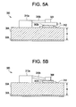
- FIGS. 5A and 5B illustrate sectional views taken along section 5-5 of the MEMS switch 300 shown in FIG. 4 , in (a) the OFF state ( FIG. 5A ), and (b) the ON state ( FIG. 5B ).
- the switch movable element 308 is generally positioned at a position separated from the microstrip lines 302a and 302b by a height h. In this case, the height (h) is approximately several micrometers (um). If, therefore, no driving voltage is applied to the switch electrode 312, the switch movable element 308 is not in contact with the microstrip lines 302a and 302b.
- the switch movable element 308 has the portions opposing the microstrip lines 302a and 302b. Since a capacitor structure is formed by switch moveable element 308 and these portions of microstrip lines 302a and 302b, the microstrip lines 302a and 302b are capacitively coupled to each other through the switch movable element 308. A capacitance between the switch movable element 308 and the microstrip lines 302a and 302b is proportional to the opposing area between the switch movable element 308 and microstrip lines 302a and 302b.
- the switch movable element 308 is formed to have the width a smaller than the width W of each of the microstrip lines 302a and 302b, thereby decreasing the opposing area and the capacitance formed between the switch movable element 308 and opposing portions of microstrip lines 302a and 302b. Since this weakens the capacitive coupling between the microstrip lines 302a and 302b, energy leakage can be suppressed in the OFF state of the MEMS switch 300.
- the MEMS switch 300 described above in FIGS. 3-5B is merely an exemplary embodiment of the construction of a MEMS switch that can be employed in the MEMS switch modules and diverter switch modules in accordance with exemplary embodiments of the present invention.
- the MEMS switch as described herein may be constructed in various other configurations.
- the support structure 310 may include a membrane, a cantilever, a deflectable membrane, a diaphragm, a flexure member, a cavity, a surface micro-machined structure, a comb structure, a bridge, or the like.
- the rest position of the membrane may correspond to the OFF/ON state, and any deflection experienced by the membrane may cause the switch to flip to the opposite state.
- the size and scalability of the MEMS switches used as switching components in the OLTC advantageously facilitate ease in packaging. Furthermore, the use of MEMS switches advantageously eliminates the need for immersing the on-load tap changer in an enclosure with insulating media such as oil or SF6 gas as typically done for conventional OLTC switches. It is contemplated that the OLTC with MEMS switching technology can be housed in an air-filled enclosure apart from the transformer unit, making the OLTC more easily available for maintenance.
- the MEMS switches used herein provide simplicity for designers since MEMS switches are real mechanical switches without the problems typically associated with conventional mechanical switches currently used in conventional on-load tap changers.
Landscapes
- Micromachines (AREA)
- Housings And Mounting Of Transformers (AREA)
- Protection Of Transformers (AREA)
- Axle Suspensions And Sidecars For Cycles (AREA)
Abstract
Description
- The subject matter disclosed herein relates to on-load tap changers for high voltage devices, and specifically to on-load tap changers for a high power transformer utilizing micro-electromechanical system (MEMS) technology.
- Currently, a complex mechanical switching assembly accomplishes on-load tap changers (OLTC). Mechanical OLTC mechanisms include an electric motor for charging powerful springs to open and close switches in the switching assembly of these OLTC mechanisms. The switches in the switching assembly are mechanically actuated on and off in a sequence coordinated by mechanical interlocks to orchestrate the switch openings and closings with the correct timing. These mechanical interlocks can bind and prevent switching from occurring. Although much development has been done to reduce switch contact electrical stress (such as reducing arcing when each switch opens), a main failure mode is switch contact failure. Furthermore, because the OLTC switch assembly has many integrated and mechanical moving parts, it has frequent problems and must be maintained regularly which can be costly. Furthermore, because the conventional OLTC switch assembly is immersed in an insulating media such as oil or SF6 gas to reduce the arcing problem, the maintenance on OLTC switch assembly can be costly and time consuming. Mechanical OLTC mechanisms are also large, slow and noisy, which may be undesirable. The mechanical moving parts of the conventional OLTC are the source of a significant portion of the problems in power transformers that include an OLTC.
- Solid-state switching devices have been used to reduce a few failure modes, but are known to have other failures or disadvantages when used as a switching component in a transformer on-load tap changer application. It is well known that semiconductor switching means exhibit parasitic energy losses and undesirable off-state leaks. Semiconductor switches also have forward voltage drop even when they are on. When a semiconductor switch is in an open position it still lets through a little bit of current, which is undesirable. Although solid-state switches can provide high switching speeds, they suffer from significant power losses and can be very costly.
- Accordingly, it is desirable to have an on-load tap changer for a high powered transformer using switching technology that is cost-effective and is capable of switching less than one micro-second and in a fashion to be arcless by diverting the energy. It is further desirable to have an on-load tap changer for a high-powered transformer using switching technology that can reduce or eliminate the switching failure modes of a conventional switch and eliminate the parasitic energy losses of a semiconducting switching means.
- According to one aspect of the invention, an on-load tap changer for a transformer winding is provided. The OLTC includes a first micro-electromechanical system (MEMS) switch module directly coupled in series with a first tap on the transformer winding and a neutral terminal; a second MEMS switch module directly coupled in series with a second tap on the transformer winding and the neutral terminal; and a controller operably coupled to the first MEMS switch module and the second MEMS switch module, the controller is configured to generate a first and second signal to be received by the first and second MEMS switch modules respectively to induce the first MEMS switch module to transition to a closed position and induce the second MEMS switch module to transition to an open position to obtain a first predetermined turns ratio on the transformer winding at a first time, the controller further configured to generate a third signal to the second MEMS switch module to induce the second MEMS switch module to transition to a closed position at a second time after the first time, the controller further configured to generate a fourth signal to be received by the first MEMS switch module at a third time after the second time, the first MEMS switch module configured to transition from the closed position to an open position at a detected zero crossing of an alternating current in response to the fourth signal to obtain a second predetermined turns ratio on the transformer winding.
- According to another aspect of the invention, an OLTC for a transformer winding is provided. The on-load tap changer includes a first micro-electromechanical system (MEMS) switch module directly coupled in series with a first tap on the transformer winding and a neutral terminal; a second MEMS switch module directly coupled in series with a second tap on the transformer winding and the neutral terminal; a controller operably coupled to the first MEMS switch module and the second MEMS switch module, the controller is configured to generate a first and second signal to be received by the first and second MEMS switch modules respectively to induce the first MEMS switch module to transition to a closed position and induce the second MEMS switch module to transition to an open position to obtain a first predetermined turns ratio on the transformer winding at a first time, the controller further configured to generate a third signal to the second MEMS switch module to induce the second MEMS switch module to transition to a closed position at a second time after the first time, the controller further configured to generate a fourth signal to be received by the first MEMS switch module at a third time after the second time, the first MEMS switch module configured to transition from the closed position to an open position at a detected zero crossing of an alternating current in response to the fourth signal to obtain a second predetermined turns ratio on the transformer winding; and control circuitry coupled to the first MEMS switch module and the second MEMS switch module, the control circuitry configured to prevent the creation of high circulating current between transformer windings when the first MEMS switch module and the second MEMS switch module are each in the closed position.
- According to yet another aspect of the invention, a method for assembling an OLTC for a transformer winding is provided. The method includes coupling a first micro-electromechanical system (MEMS) switch module in series with a first tap on the transformer winding and a neutral terminal; coupling a second MEMS switch module coupled in series with a second tap on the transformer winding and the neutral terminal; and operably coupling a controller to the first MEMS switch module and the second MEMS switch module, the controller is configured to generate a first and second signal to be received by the first and second MEMS switch modules respectively to induce the first MEMS switch module to transition to a closed position and induce the second MEMS switch module to transition to an open position to obtain a first predetermined turns ratio on the transformer winding at a first time, the controller further configured to generate a third signal to the second MEMS switch module to induce the second MEMS switch module to transition to a closed position at a second time after the first time, the controller further configured to generate a fourth signal to be received by the first MEMS switch module at a third time after the second time, the first MEMS switch module configured to transition from the closed position to an open position at a detected zero crossing of an alternating current in response to the fourth signal to obtain a second predetermined turns ratio on the transformer winding.
- These and other advantages and features will become more apparent from the following description taken in conjunction with the drawings.
- There follows a detailed description of embodiments of the invention by way of example only with reference to the accompanying drawings, in which:
-
FIG. 1 is a schematic diagram of an OLTC for a transformer winding utilizing a plurality MEMS of switch modules in accordance with an exemplary embodiment as disclosed herein; -
FIG. 2 is a flow diagram that provides a method for operating an OLTC that utilizes MEMS switch technology to change the turns ratio on a transformer winding in accordance with an exemplary embodiment as disclosed herein; -
FIG. 3 is a perspective view showing the structure of an exemplary MEMS switch for each of the plurality of MEMS switch modules in accordance with one exemplary embodiment as disclosed herein; -
FIG. 4 is a cross-sectional view of the MEMS switch shown inFIG. 3 along section 4-4; -
FIG. 5A illustrates a cross-sectional view along section 5-5 of the MEMS switch of -
FIG. 3 in an OFF state in accordance with an exemplary embodiment as disclosed herein; and -
FIG. 5B illustrates a cross-sectional view along section 5-5 of the MEMS switch ofFIG. 3 in an ON state in accordance with an exemplary embodiment as disclosed herein; - The detailed description explains embodiments of the invention, together with advantages and features, by way of example with reference to the drawings.
- Exemplary embodiments are directed to an OLTC that utilizes MEMS switch technology (e.g., independent MEMS based switches) for changing the amount of turns or turns ratio on a transformer winding, and effectively the output voltage of the alternating current (AC) across the transformer winding and a method for assembling the same. Exemplary embodiments are also directed to a method for operating an OLTC that utilizes MEMS switch technology to change the turns ratio on a transformer winding. In the exemplary embodiments, the use of MEMS switches reduce or eliminate switching failure modes (e.g., switch contact failure) of a conventional switch and avoid the parasitic energy losses of a semiconducting switching means. The exemplary embodiments provide an OLTC that utilizes MEMS switches capable of switching in less than one microsecond and include an embedded method to eliminate arcing as the switches are opened.
- As used herein, the terms "off", "on", "open", "closed", "series", and "parallel" have their ordinary meaning in the electronic arts.
-
FIG. 1 illustrates a simplified schematic of an on-load tap changer 10 coupled to a transformer winding 12 of a transformer unit (not shown) having an internal coil and core assemblies (not shown) in accordance with one exemplary embodiment. Although the components of the transformer unit are not shown in detail, it should be understood that the transformer winding 12 as described herein can be part of any conventional transformer unit and should not be limited to any one type of transformer configuration. The transformer winding 12 has aline terminal 14 at one end and a neutral orground terminal 16 at the other end. - The on-
load tap changer 10 includes a plurality ofMEMS switch modules 18A-18H electrically coupled directly in series with a plurality oftaps 20A-20H respectively, where the taps are connected to different transformer windings as shown. Each tap allows a predetermined number of turns to be selected for the transformer winding providing the transformer winding with a variable turns ratio and enabling voltage regulation of the AC output across the transformer winding. In general, for example, whenMEMS switch module 18B closes to make a tap connection withtap 20B while the other MEMS switch modules are open, the transformer winding 12 will obtain a first predetermined turns ratio. In this same example, whenMEMS switch module 18C closes to make a tap connection withtap 20C while the other MEMS switch modules (includingMEMS switch module 18A) are open, the transformer winding 12 will obtain a second predetermined turns ratio different from the first predetermined turns ratio. As such, the voltage output of the transformer winding 12 can be "stepped down" or increased (e.g., moving fromtap 20B to tap 20A) or "stepped up" or decreased (e.g., moving fromtap 20B to tap 20C) accordingly. Only one MEMS switch module may be closed during normal transformer operation in accordance with one embodiment. - The on-
load tap changer 10 may include more or less MEMS switch modules and taps than are shown inFIG. 1 depending on the application. However, for purposes of simplification only, eight modules are shown inFIG. 1 . For ease of discussion,MEMS switch module 18B andMEMS switch module 18C along with their respective taps (tap 20B andtap 20C) will be discussed in greater detail to illustrate, by way of example, the switching operations of the on-load tap changer 10 utilizing MEMS switch technology in accordance with one exemplary embodiment. - The on-
load tap changer 10 further includescontrol circuitry 21 electrically coupled between the plurality of MEMS switch modules and theneutral terminal 16 as shown. Thecontrol circuitry 21 is configured to prevent large circulating current between windings during a tap switching operation in accordance with one embodiment. In other words, the control circuitry controls the switching operation and operably diverts undesired energy from the transformer winding during a tap switching operation, which will be discussed in greater detail below. - The
control circuitry 21 includes a firstdiverter switch module 22, a seconddiverter switch module 24, a thirddiverter switch module 26, a fourthdiverter switch module 28. Thecontrol circuitry 21 further includes a first andsecond diverter impedance MEMS switch module diverter switch module 22 is electrically coupled betweenMEMS switch module 18B andneutral terminal 16. The firstdiverter switch module 22 is also electrically coupled betweenMEMS switch module 18C andneutral terminal 16. The firstdiverter switch module 22 is configured to transition between a first operational position and a second operational position depending on the desired turns ratio for the transformer winding. The seconddiverter switch module 24 is electrically coupled betweenMEMS switch module 18B and the firstdiverter switch module 22. The first diverter impedance is electrically coupled in parallel with the seconddiverter switch module 24 and is electrically coupled toMEMS switch module 18B as shown. The thirddiverter switch module 26 is electrically coupled betweenMEMS switch module 18C and the firstdiverter switch module 22. Thesecond diverter impedance 32 is electrically coupled in parallel with the thirddiverter switch module 26. Finally, the fourthdiverter switch module 28 is electrically coupled in series with thefirst diverter impedance 30 and thesecond diverter impedance 32 and is in parallel connection with the firstdiverter switch module 22. - In accordance with one exemplary embodiment, a
controller 40 is in signal communication with theMEMS switch modules 18A-18H and thediverter switch modules controller 40 is configured to coordinate the switching operations of the MEMS switch modules and the diverter switch modules in order to create (e.g. close) tap connections, break tap connections (e.g., open), prevent tap connections, as well as switch between taps (e.g., open and close sequences) to effectively change or adjust the level of voltage available at the transformer winding to the neutral terminal, by generating and sending signals to the MEMS switch modules and the diverter switch modules to induce the switch modules to open or close at a predetermined time in accordance with one exemplary embodiment. Thecontroller 40 sends signals to the MEMS switch modules and diverter switch modules in accordance with predetermined switching sequences to make tap connections, break tap connections, prevent tap connections, and switch between taps. Thecontroller 40 is configured to receive feedback (e.g., switch position) from each of the MEMS switch modules in accordance with one embodiment. - The
controller 40 can be an integral component of the on-load tap changer 10 in accordance with one exemplary embodiment. In an alternate embodiment, thecontroller 40 is a component of a system or sub-system that incorporates the transformer unit with the on-load tap changer 10. In accordance with one exemplary embodiment, thecontroller 40 comprises a processor having a combination of hardware and/or software/firmware with a computer program that, when loaded and executed, permits the processor of the controller to operate such that it carries out the methods/operations described herein. - The switching sequences executed by the
controller 40 will now be discussed by way of example with reference to the on-load tap changer configuration shown inFIG. 1 and described above. More specifically, a normal transformer operation and a tap switching operation executed by thecontroller 40 will be described by way of example. This will illustrate the operation of the on-load tap changer 10 that can create a tap connection before releasing another tap connection, which in this example is betweentap 20B to tap 20C, utilizing MEMS switch technology. - Now referring to
FIG. 2 , a method for operating an OLTC that utilizes MEMS switch technology to change the turns ratio on a transformer winding in accordance with one exemplary embodiment will be discussed by way of example with reference to the OLTC shown inFIG. 1 . - At
operational block 200, begin a tap-switching operation with initial conditions in place. The initial conditions that are in place includesMEMS switch module 18B being closed making a connection withtap 20B whileMEMS switch module 18C is open (and all other tap switches, 18A, 18D-18H are open), the firstdiverter switch module 22 being placed in the first operational position (position A), the seconddiverter switch module 24 being closed, and the third and fourthdiverter switch module diverter switch module 24 toneutral terminal 16. Thecontroller 40 enables these initial conditions to be met by generating and sending signals to the switching components in a predetermined sequence in accordance with one exemplary embodiment. Of course, the initial conditions set in place could be whereMEMS switch module 18C is closed and theMEMS switch module 18B is open or where any one of the MEMS switch modules are closed while the remaining are open. However, only the initial conditions described above will be used in this example for the sake of discussion. - At
operational block 202, closeMEMS switch module 18C to create a tap connection withtap 20C. TheMEMS switch module 18C closes by receiving a signal from thecontroller 40 that induces theMEMS switch module 18C to close in accordance with one exemplary embodiment. At this point, a tap switching operation has been initiated bycontroller 40 in accordance with one embodiment. - At
operational block 204, open the seconddiverter switch module 24 to enable load current on the transformer winding to travel through thefirst diverter impedance 30. This enables the energy atMEMS switch module 18B to dissipate throughfirst diverter impedance 30. Thecontroller 40 sends a signal to the seconddiverter switch module 24 to induce the seconddiverter switch module 24 to open in accordance with one exemplary embodiment. - At
operational block 206, close the fourthdiverter switch module 28 to enable load current on the transformer winding to travel through thefirst diverter impedance 30 and thesecond diverter impedance 32. Thefirst diverter impedance 30 and thesecond diverter impedance 32 are used to divert the energy stored in the windings betweenMEMS switch module 20B andMEMS switch module 20C in accordance with one exemplary embodiment. The fourthdiverter switch module 28 closes by receiving a signal from thecontroller 40 to induce the fourthdiverter switch module 28 to close in accordance with one exemplary embodiment. - At
operational block 208, place the firstdiverter switch module 22 in the second operational position (position B). This will enable load current to travel between the secondMEMS switch module 18C and theneutral terminal 16 and enable the transformer winding to obtain a second predetermined turns ratio. - At
operational block 210, open the fourthdiverter switch module 28 to enable load current to pass through thesecond diverter impedance 32. This enables the energy atMEMS switch module 18C to dissipate throughsecond diverter impedance 32. The fourthdiverter switch module 28 opens by receiving a signal from thecontroller 40 to induce the fourthdiverter switch module 28 to open in accordance with one exemplary embodiment. - At
operation block 212, close the thirddiverter switch module 26 to enable load current to bypass thesecond diverter impedance 32 and travel through the thirddiverter switch module 26 to theneutral terminal 16 obtaining a second predetermined turns ratio for transformer winding 12. The thirddiverter switch module 26 closes by receiving a signal from thecontroller 40 to induce the thirddiverter switch module 26 to close in accordance with one exemplary embodiment. - At
operation block 214, openMEMS switch module 18B at a detected zero crossing of the alternating current. This completes the tap switching operation. In accordance with one embodiment,MEMS switch module 18B opens at the detected zero crossing of the alternating current in response to receiving a signal from the controller to induce theMEMS switch module 18B to open. - The flow diagram depicted herein is just an example. There may be many variations to this diagram or the steps (or operations) described therein without departing form the spirit of the invention. For instance, the operational steps may be performed in a differing order, or steps may be added, deleted or modified. All these variations are considered a part of the claimed invention. It should be understood that similar operational steps can be taken to form different tap connections along the transformer winding.
- In accordance with one exemplary embodiment, each of the MEMS switch modules comprises one or more MEMS based switches configured to open during a detected zero crossing of an alternating current or bypass asymmetric current through a bypass method. In accordance with one embodiment, the MEMS based switches described herein include an integral current sensor that can detect the zero crossing of the alternating current. Furthermore, the MEMS based switches described herein are configured to have zero leakage in the open position in accordance with one embodiment.
- In accordance with one exemplary embodiment, each of the diverter switch modules comprises one or more MEMS based switches similar to those described above.
- In accordance with one exemplary embodiment, each MEMS switch module comprises of an array of MEMS based switches having a series configuration, a parallel configuration or a combination of both. It is contemplated that such MEMS based switches alone or in combination with other MEMS based switches used in this OLTC application can withstand high voltage/high current transformers without failing.
- Now referring to
FIG. 3 illustrating one example of aMEMS switch 300 and its basic components that can be used in the exemplary embodiments described herein. TheMEMS switch 300 comprises a switchmovable element 308,support structure 310, and switch electrode (driving means) 312. TheMEMS switch 300 is formed on adielectric substrate 304 together with two RF microstrip lines (distributed constant lines) 302a and 302b. A ground (GND)plate 306 is disposed on the lower surface of thedielectric substrate 304. Themicrostrip lines - The
switch electrode 312 is disposed between the microstrip lines 2a and 2b on thedielectric substrate 304. Theswitch electrode 312 is formed to have a height lower than that of each of themicrostrip lines switch electrode 312 on the basis of an electrical signal. The switchmovable element 308 is arranged above theswitch electrode 312. The switchmovable element 308 is made of a conductive member. A capacitor structure is therefore formed by theswitch electrode 312 and switchmovable element 308 opposing each other. - The
support structure 310 for supporting the switchmovable element 308 includes apost portion 310a and anarm portion 310b. Thepost portion 310a is fixed on thedielectric substrate 304 apart from the gap G between themicrostrip lines arm portion 310b extends from one end of the upper surface of thepost portion 310a to the gap G. Thesupport structure 310 is made of a dielectric, semiconductor, or conductor. The switchmovable element 308 is fixed on a distal end of thearm portion 310b of thesupport structure 310. - As shown in
FIG. 4 , the switchmovable element 308 has a length L that is larger than the gap G. With this structure,distal end portions movable element 308 oppose parts ofdistal end portions microstrip lines distal end portions movable element 308 are defined as portions each extending by a length (L-G)/2 from a corresponding one of the two ends of the switchmovable element 308. Thedistal end portions microstrip lines microstrip lines - A width of the switch
movable element 308 is smaller than the width W of each of themicrostrip lines distal end portions movable element 308 is therefore smaller than that of each of thedistal end portions microstrip lines -
FIGS. 5A and 5B illustrate sectional views taken along section 5-5 of theMEMS switch 300 shown inFIG. 4 , in (a) the OFF state (FIG. 5A ), and (b) the ON state (FIG. 5B ). As shown inFIG. 5A , the switchmovable element 308 is generally positioned at a position separated from themicrostrip lines switch electrode 312, the switchmovable element 308 is not in contact with themicrostrip lines - However, the switch
movable element 308 has the portions opposing themicrostrip lines moveable element 308 and these portions ofmicrostrip lines microstrip lines movable element 308. A capacitance between the switchmovable element 308 and themicrostrip lines movable element 308 andmicrostrip lines - The switch
movable element 308 is formed to have the width a smaller than the width W of each of themicrostrip lines movable element 308 and opposing portions ofmicrostrip lines microstrip lines MEMS switch 300. - The
MEMS switch 300 described above inFIGS. 3-5B is merely an exemplary embodiment of the construction of a MEMS switch that can be employed in the MEMS switch modules and diverter switch modules in accordance with exemplary embodiments of the present invention. It will be appreciated by those of ordinary skill in the art that the MEMS switch as described herein may be constructed in various other configurations. For example, thesupport structure 310 may include a membrane, a cantilever, a deflectable membrane, a diaphragm, a flexure member, a cavity, a surface micro-machined structure, a comb structure, a bridge, or the like. In exemplary embodiments where a membrane is used, the rest position of the membrane may correspond to the OFF/ON state, and any deflection experienced by the membrane may cause the switch to flip to the opposite state. - The size and scalability of the MEMS switches used as switching components in the OLTC advantageously facilitate ease in packaging. Furthermore, the use of MEMS switches advantageously eliminates the need for immersing the on-load tap changer in an enclosure with insulating media such as oil or SF6 gas as typically done for conventional OLTC switches. It is contemplated that the OLTC with MEMS switching technology can be housed in an air-filled enclosure apart from the transformer unit, making the OLTC more easily available for maintenance. The MEMS switches used herein provide simplicity for designers since MEMS switches are real mechanical switches without the problems typically associated with conventional mechanical switches currently used in conventional on-load tap changers.
- While the invention has been described in detail in connection with only a limited number of embodiments, it should be readily understood that the invention is not limited to such disclosed embodiments. Rather, the invention can be modified to incorporate any number of variations, alterations, substitutions or equivalent arrangements not heretofore described, but which are commensurate with the spirit and scope of the invention. Additionally, while various embodiments of the invention have been described, it is to be understood that aspects of the invention may include only some of the described embodiments. Accordingly, the invention is not to be seen as limited by the foregoing description, but is only limited by the scope of the appended claims.
- Various aspects and embodiments of the present invention are defined by the following numbered clauses:
- 1. An on-load tap changer for a transformer winding, comprising:
- a first micro-electromechanical system (MEMS) switch module directly coupled in series with a first tap on the transformer winding and a neutral terminal;
a second MEMS switch module directly coupled in series with a second tap on the transformer winding and the neutral terminal; and
a controller operably coupled to the first MEMS switch module and the second MEMS switch module, the controller is configured to generate a first and second signal to be received by the first and second MEMS switch modules respectively to induce the first MEMS switch module to transition to a closed position and induce the second MEMS switch module to transition to an open position to obtain a first predetermined turns ratio on the transformer winding.
- a first micro-electromechanical system (MEMS) switch module directly coupled in series with a first tap on the transformer winding and a neutral terminal;
- 2. The on-load tap changer as in clause 1, wherein the controller is configured to generate the first and second signal to be received by the first and second MEMS switch modules respectively to induce the first MEMS switch module to transition to the closed position and induce the second MEMS switch module to transition to the open position to obtain the first predetermined turns ratio on the transformer winding at a first time, the controller further configured to generate a third signal to the second MEMS switch module to induce the second MEMS switch module to transition to a closed position at a second time after the first time, the controller further configured to generate a fourth signal to be received by the first MEMS switch module at a third time after the second time, the first MEMS switch module configured to transition from the closed position to an open position at a detected zero crossing of an alternating current in response to the fourth signal to obtain a second predetermined turns ratio on the transformer winding.
- 3. The on-load tap changer as in clause 2, further comprising control circuitry coupled to the first MEMS switch module and the second MEMS switch module, the control circuitry configured to prevent the creation of high circulating current between transformer windings when the first MEMS switch module and the second MEMS switch module are each in the closed position.
- 4. The on-load tap changer as in clause 3, wherein the control circuitry comprises a first diverter switch module coupled between the first MEMS switch module and the neutral terminal and further coupled between the second MEMS switch module and the neutral terminal, the first diverter switch module is configured to transition to a first operational position at the first time to enable load current to pass between the first MEMS switch module and the neutral terminal and to obtain the first predetermined turns ratio for the transformer winding.
- 5. The on-load tap changer as in clause 4, wherein the control circuitry further comprises a second diverter switch module coupled between the first MEMS switch module and the first diverter switch module, the second diverter switch module coupled in parallel with a first diverter impedance, the second diverter switch module is configured to transition to an open position at a fourth time after the second time in response to a fifth signal generated by the controller to enable load current to pass through the first diverter impedance during a tap switching operation, the second diverter switch module is in a closed position at the first time.
- 6. The on-load tap changer as in
clause 5, wherein the control circuitry further comprises a third diverter switch module coupled between the second MEMS switch module and the first diverter switch module, the third diverter switch module coupled in parallel with a second diverter impedance, the third diverter switch module is in an open position at the time. - 7. The on-load tap changer as in clause 6, wherein the control circuitry further comprises a fourth diverter switch module coupled between the first diverter impedance and the second diverter impedance and further coupled in parallel with the first diverter switch module, the fourth diverter switch module is configured to transition to a closed position at a fifth time after the fourth time in response to a sixth signal generated by the controller to enable load current to pass through the first diverter impedance and the second diverter impedance preventing the creation of high circulating current between transformer windings during the tap switching operation, the fourth diverter switch module is in an open position at the first time.
- 8. The on-load tap changer as in clause 7, wherein the first diverter switch module is configured to transition from the first operational position to a second operational position at a sixth time after the fifth time in response to a seventh signal generated by the controller to enable load current to pass between the second MEMS switch module and the neutral terminal and to obtain the second predetermined turns ratio for the transformer winding.
- 9. The on-load tap changer as in clause 8, wherein the fourth diverter switch module is configured to transition to the open position at a seventh time after the sixth time in response to an eighth signal generated by the controller to enable current load to pass through the second diverter impedance during the tap switching operation.
- 10. The on-load tap changer as in clause 9, wherein the third diverter switch module is configured to transition to a closed position at an eighth time after the seventh time in response to a ninth signal generated by the controller to enable load current to pass between the second MEMS switch module and the neutral terminal and provide the transformer winding with the second predetermined turns ratio.
- 11. The on-load tap changer as in
clause 10, wherein the first MEMS switch module transitions from the closed position to the open position at the detected zero crossing of the alternating current in response to the fourth signal to obtain the second predetermined turns ratio on the transformer winding at the third time after the eighth time. - 12. The on-load tap changer as in clause 1, wherein the first and second MEMS switch modules each include at least one MEMS switch that operably has zero leakage while in the open position.
- 13. The on-load tap changer as in clause 1, wherein the first and second MEMS switch modules each have switching speeds of less than one microsecond.
- 14. The on-load tap changer as in clause 2, wherein the first and second MEMS switch modules each include at least one current sensor for detecting a zero crossing of the alternating current.
- 15. An on-load tap changer for a transformer winding, comprising:
- a first micro-electromechanical system (MEMS) switch module directly coupled in series with a first tap on the transformer winding and a neutral terminal;
- a second MEMS switch module directly coupled in series with a second tap on the transformer winding and the neutral terminal;
- a controller operably coupled to the first MEMS switch module and the second MEMS switch module, the controller is configured to generate a first and second signal to be received by the first and second MEMS switch modules respectively to induce the first MEMS switch module to transition to a closed position and induce the second MEMS switch module to transition to an open position to obtain a first predetermined turns ratio on the transformer winding at a first time, the controller further configured to generate a third signal to the second MEMS switch module to induce the second MEMS switch module to transition to a closed position at a second time after the first time; and
- control circuitry coupled to the first MEMS switch module and the second MEMS switch module, the control circuitry configured to prevent the creation of high circulating current between transformer windings when the first MEMS switch module and the second MEMS switch module are each in the closed position.
- 16. The on-load tap changer as in clause 15, wherein the controller is further configured to generate a fourth signal to be received by the first MEMS switch module at a third time after the second time, the first MEMS switch module configured to transition from the closed position to an open position at a detected zero crossing of an alternating current in response to the fourth signal to obtain a second predetermined turns ratio on the transformer winding, and wherein the first MEMS switch module includes a first current sensor for detecting the zero crossing of the alternating current.
- 17. The on-load tap changer as in
clause 16, wherein the second MEMS switch module includes a second current sensor for detecting the zero crossing of the alternating current. - 18. The on-load tap changer as in clause 17, wherein the first current sensor is integral to the first MEMS switch module and the second current sensor is integral to the second MEMS switch module.
- 19. The on-load tap changer as in clause 15, wherein the first and second MEMS switch modules each include at least one MEMS switch that operably has zero leakage in the open position.
- 20. The on-load tap changer as in clause 15, wherein the first and second MEMS switch modules each have switching speeds of less than one microsecond.
Claims (10)
- An on-load tap changer (10) for a transformer winding (12), comprising:a first micro-electromechanical system (MEMS) switch module (18) directly coupled in series with a first tap on the transformer winding (12) and a neutral terminal (16);a second MEMS switch module (18) directly coupled in series with a second tap on the transformer winding (12) and the neutral terminal (16); anda controller (40) operably coupled to the first MEMS switch module (18) and the second MEMS switch module (18), the controller (40) is configured to generate a first and second signal to be received by the first and second MEMS switch modules (18) respectively to induce the first MEMS switch module (18) to transition to a closed position and induce the second MEMS switch module (18) to transition to an open position to obtain a first predetermined turns ratio on the transformer winding (12).
- The on-load tap changer (10) as in claim 1, wherein the controller (40) is configured to generate the first and second signal to be received by the first and second MEMS switch modules (18) respectively to induce the first MEMS switch module (18) to transition to the closed position and induce the second MEMS switch module (18) to transition to the open position to obtain the first predetermined turns ratio on the transformer winding (12) at a first time, the controller (40) further configured to generate a third signal to the second MEMS switch module (18) to induce the second MEMS switch module (18) to transition to a closed position at a second time after the first time, the controller (40) further configured to generate a fourth signal to be received by the first MEMS switch module (18) at a third time after the second time, the first MEMS switch module (18) configured to transition from the closed position to an open position at a detected zero crossing of an alternating current in response to the fourth signal to obtain a second predetermined turns ratio on the transformer winding (12).
- The on-load tap changer (10) as in claim 2, further comprising control circuitry (21) coupled to the first MEMS switch module (18) and the second MEMS switch module (18), the control circuitry (21) configured to prevent the creation of high circulating current between transformer winding (12)s when the first MEMS switch module (18) and the second MEMS switch module (18) are each in the closed position; the control circuitry (21) comprises a first diverter switch module (22-28) coupled between the first MEMS switch module (18) and the neutral terminal (16) and further coupled between the second MEMS switch module (18) and the neutral terminal (16), the first diverter switch module (22-28) is configured to transition to a first operational position at the first time to enable load current to pass between the first MEMS switch module (18) and the neutral terminal (16) and to obtain the first predetermined turns ratio for the transformer winding (12); a second diverter switch module (22-28) coupled between the first MEMS switch module (18) and the first diverter switch module (22-28), the second diverter switch module (22-28) coupled in parallel with a first diverter impedance, the second diverter switch module (22-28) is configured to transition to an open position at a fourth time after the second time in response to a fifth signal generated by the controller (40) to enable load current to pass through the first diverter impedance during a tap switching operation, the second diverter switch module (22-28) is in a closed position at the first time; a third diverter switch module (22-28) coupled between the second MEMS switch module (18) and the first diverter switch module (22-28), the third diverter switch module (22-28) coupled in parallel with a fisrt diverter impedance (32), the third diverter switch module (22-28) is in an open position at the time; a fourth diverter switch module (22-28) coupled between the first diverter impedance and the first diverter impedance (30) and further coupled in parallel with the first diverter switch module (22-28), the fourth diverter switch module (22-28) is configured to transition to a closed position at a fifth time after the fourth time in response to a sixth signal generated by the controller (40) to enable load current to pass through the first diverter impedance and the fisrt diverter impedance (32) preventing the creation of high circulating current between transformer winding (12)s during the tap switching operation, the fourth diverter switch module (22-28) is in an open position at the first time; wherein the first diverter switch module (22-28) is configured to transition from the first operational position to a second operational position at a sixth time after the fifth time in response to a seventh signal generated by the controller (40) to enable load current to pass between the second MEMS switch module (18) and the neutral terminal (16) and to obtain the second predetermined turns ratio for the transformer winding (12); the fourth diverter switch module (22-28) is configured to transition to the open position at a seventh time after the sixth time in response to an eighth signal generated by the controller (40) to enable current load to pass through the fisrt diverter impedance (32) during the tap switching operation; the third diverter switch module (22-28) is configured to transition to a closed position at an eighth time after the seventh time in response to a ninth signal generated by the controller (40) to enable load current to pass between the second MEMS switch module (18) and the neutral terminal (16) and provide the transformer winding (12) with the second predetermined turns ratio; the first MEMS switch module (18) transitions from the closed position to the open position at the detected zero crossing of the alternating current in response to the fourth signal to obtain the second predetermined turns ratio on the transformer winding (12) at the third time after the eighth time.
- The on-load tap changer (10) as in any of the preceding claims, wherein the first and second MEMS switch modules (18) each include at least one MEMS switch that operably has zero leakage while in the open position.
- The on-load tap changer (10) as in claim 2, wherein the first and second MEMS switch modules (18) each include at least one current sensor for detecting a zero crossing of the alternating current.
- An on-load tap changer (10) for a transformer winding (12), comprising:a first micro-electromechanical system (MEMS) switch module directly coupled in series with a first tap on the transformer winding (12) and a neutral terminal (16);a second MEMS switch module (18) directly coupled in series with a second tap on the transformer winding (12) and the neutral terminal (16);a controller (40) operably coupled to the first MEMS switch module (18) and the second MEMS switch module (18), the controller (40) is configured to generate a first and second signal to be received by the first and second MEMS switch modules (18) respectively to induce the first MEMS switch module (18) to transition to a closed position and induce the second MEMS switch module (18) to transition to an open position to obtain a first predetermined turns ratio on the transformer winding (12) at a first time, the controller (40) further configured to generate a third signal to the second MEMS switch module (18) to induce the second MEMS switch module (18) to transition to a closed position at a second time after the first time; andcontrol circuitry (21) coupled to the first MEMS switch module (18) and the second MEMS switch module (18), the control circuitry (21) configured to prevent the creation of high circulating current between transformer winding (12)s when the first MEMS switch module (18) and the second MEMS switch module (18) are each in the closed position.
- The on-load tap changer (10) as in claim 6, wherein the controller (40) is further configured to generate a fourth signal to be received by the first MEMS switch module (18) at a third time after the second time, the first MEMS switch module (18) configured to transition from the closed position to an open position at a detected zero crossing of an alternating current in response to the fourth signal to obtain a second predetermined turns ratio on the transformer winding (12), and wherein the first MEMS switch module (18) includes a first current sensor for detecting the zero crossing of the alternating current.
- The on-load tap changer (10) as in claim 7, wherein the second MEMS switch module (18) includes a second current sensor for detecting the zero crossing of the alternating current.
- The on-load tap changer (10) as in any of claims 6 to 8, wherein the first and second MEMS switch modules (18) each include at least one MEMS switch that operably has zero leakage in the open position.
- The on-load tap changer (10) as in any of claims 6 to 9, wherein the first and second MEMS switch modules (18) each have switching speeds of less than one microsecond.
Applications Claiming Priority (1)
| Application Number | Priority Date | Filing Date | Title |
|---|---|---|---|
| US12/500,212 US8203319B2 (en) | 2009-07-09 | 2009-07-09 | Transformer on-load tap changer using MEMS technology |
Publications (3)
| Publication Number | Publication Date |
|---|---|
| EP2273520A2 true EP2273520A2 (en) | 2011-01-12 |
| EP2273520A3 EP2273520A3 (en) | 2011-02-16 |
| EP2273520B1 EP2273520B1 (en) | 2012-09-19 |
Family
ID=42938572
Family Applications (1)
| Application Number | Title | Priority Date | Filing Date |
|---|---|---|---|
| EP10168517A Not-in-force EP2273520B1 (en) | 2009-07-09 | 2010-07-06 | Transformer on-load tap changer using mems technology |
Country Status (4)
| Country | Link |
|---|---|
| US (1) | US8203319B2 (en) |
| EP (1) | EP2273520B1 (en) |
| JP (1) | JP5237994B2 (en) |
| CN (1) | CN101958651B (en) |
Families Citing this family (14)
| Publication number | Priority date | Publication date | Assignee | Title |
|---|---|---|---|---|
| CN103548107B (en) * | 2011-03-27 | 2016-08-24 | Abb技术有限公司 | There is the tap changer of the monitoring system of improvement |
| US9097757B2 (en) | 2011-04-14 | 2015-08-04 | National Instruments Corporation | Switching element system and method |
| US9157952B2 (en) | 2011-04-14 | 2015-10-13 | National Instruments Corporation | Switch matrix system and method |
| US8704408B2 (en) | 2011-04-14 | 2014-04-22 | National Instruments Corporation | Switch matrix modeling system and method |
| DE102012200784A1 (en) * | 2012-01-20 | 2013-07-25 | Siemens Aktiengesellschaft | A voltage compensation device and a medical imaging device with a voltage compensation device |
| DE102012103048B4 (en) * | 2012-04-10 | 2016-01-07 | Maschinenfabrik Reinhausen Gmbh | Control transformers for voltage regulation with semiconductor switching elements |
| US9287062B2 (en) | 2012-05-02 | 2016-03-15 | National Instruments Corporation | Magnetic switching system |
| US9558903B2 (en) | 2012-05-02 | 2017-01-31 | National Instruments Corporation | MEMS-based switching system |
| US9087635B2 (en) | 2012-08-24 | 2015-07-21 | General Electric Company | Load tap changer |
| DE102013101652A1 (en) * | 2013-02-20 | 2014-08-21 | Maschinenfabrik Reinhausen Gmbh | On-load tap-changer with semiconductor switching elements and method for operating an on-load tap-changer |
| US9400512B2 (en) * | 2013-12-17 | 2016-07-26 | General Electric Company | System and method for operating an on load tap changer for regulating voltage on an electric power system |
| US9320481B2 (en) | 2014-03-31 | 2016-04-26 | General Electric Company | Systems and methods for X-ray imaging |
| TWI556271B (en) * | 2014-08-13 | 2016-11-01 | 佳世達科技股份有限公司 | Transformer and control method thereof |
| US10048709B2 (en) * | 2016-09-19 | 2018-08-14 | General Electric Company | System and method for regulation of voltage on an electric power system |
Family Cites Families (22)
| Publication number | Priority date | Publication date | Assignee | Title |
|---|---|---|---|---|
| US3167703A (en) * | 1959-06-17 | 1965-01-26 | Mc Graw Edison Co | Self-regulating transformer |
| JPS5118609B1 (en) * | 1968-03-13 | 1976-06-11 | ||
| JPS61206013A (en) * | 1985-03-11 | 1986-09-12 | Nippon Electric Ind Co Ltd | Automatic voltage adjusting device |
| JPH0628913Y2 (en) * | 1988-07-20 | 1994-08-03 | 株式会社ダイヘン | Protective device for load tap changer |
| US5408171A (en) * | 1991-10-21 | 1995-04-18 | Electric Power Research Institute, Inc. | Combined solid-state and mechanically-switched transformer tap-changer |
| SE500609C2 (en) * | 1992-07-09 | 1994-07-25 | Asea Brown Boveri | Tap changer |
| JPH0795723A (en) * | 1993-09-22 | 1995-04-07 | Fuji Electric Co Ltd | Vacuum switch type load tap protector protection device |
| CA2327014C (en) * | 2000-01-12 | 2005-04-12 | Donald W. Owen | Method and apparatus for providing selectable output voltages |
| US6992543B2 (en) * | 2002-11-22 | 2006-01-31 | Raytheon Company | Mems-tuned high power, high efficiency, wide bandwidth power amplifier |
| FI20055240A7 (en) * | 2005-05-20 | 2006-11-21 | Polar Electro Oy | Per-user performance meter peripheral device, per-user performance meter and method |
| US7663456B2 (en) * | 2005-12-15 | 2010-02-16 | General Electric Company | Micro-electromechanical system (MEMS) switch arrays |
| US7633725B2 (en) * | 2005-12-20 | 2009-12-15 | General Electric Company | Micro-electromechanical system based soft switching |
| US20070139829A1 (en) * | 2005-12-20 | 2007-06-21 | General Electric Company | Micro-electromechanical system based arc-less switching |
| US7876538B2 (en) * | 2005-12-20 | 2011-01-25 | General Electric Company | Micro-electromechanical system based arc-less switching with circuitry for absorbing electrical energy during a fault condition |
| GB2435943A (en) * | 2006-03-08 | 2007-09-12 | Areva T & D Sa | Hybrid on-load tap changer |
| JP4767141B2 (en) * | 2006-09-27 | 2011-09-07 | 三菱電機株式会社 | Switching operation control method of tap switching device when loaded |
| US7332835B1 (en) * | 2006-11-28 | 2008-02-19 | General Electric Company | Micro-electromechanical system based switching module serially stackable with other such modules to meet a voltage rating |
| US7643256B2 (en) * | 2006-12-06 | 2010-01-05 | General Electric Company | Electromechanical switching circuitry in parallel with solid state switching circuitry selectively switchable to carry a load appropriate to such circuitry |
| US7542250B2 (en) * | 2007-01-10 | 2009-06-02 | General Electric Company | Micro-electromechanical system based electric motor starter |
| US9076607B2 (en) * | 2007-01-10 | 2015-07-07 | General Electric Company | System with circuitry for suppressing arc formation in micro-electromechanical system based switch |
| US7473859B2 (en) * | 2007-01-12 | 2009-01-06 | General Electric Company | Gating voltage control system and method for electrostatically actuating a micro-electromechanical device |
| JP5149550B2 (en) * | 2007-06-12 | 2013-02-20 | ゼネラル・エレクトリック・カンパニイ | Soft switching based on microelectromechanical systems |
-
2009
- 2009-07-09 US US12/500,212 patent/US8203319B2/en active Active
-
2010
- 2010-07-06 EP EP10168517A patent/EP2273520B1/en not_active Not-in-force
- 2010-07-07 JP JP2010154403A patent/JP5237994B2/en active Active
- 2010-07-09 CN CN2010102312620A patent/CN101958651B/en active Active
Non-Patent Citations (1)
| Title |
|---|
| None |
Also Published As
| Publication number | Publication date |
|---|---|
| US8203319B2 (en) | 2012-06-19 |
| EP2273520B1 (en) | 2012-09-19 |
| US20110005910A1 (en) | 2011-01-13 |
| JP2011018905A (en) | 2011-01-27 |
| EP2273520A3 (en) | 2011-02-16 |
| CN101958651B (en) | 2013-06-19 |
| CN101958651A (en) | 2011-01-26 |
| JP5237994B2 (en) | 2013-07-17 |
Similar Documents
| Publication | Publication Date | Title |
|---|---|---|
| EP2273520B1 (en) | Transformer on-load tap changer using mems technology | |
| CN101740260B (en) | Vacuum switchgear | |
| US7554222B2 (en) | Micro-electromechanical system based switching | |
| KR100407621B1 (en) | Step switch with selector | |
| EP3624159B1 (en) | A switching device | |
| TWI569298B (en) | Opening and closing device | |
| US8350509B2 (en) | Power switching system including a micro-electromechanical system (MEMS) array | |
| JP2010530119A (en) | Microelectromechanical system based switching | |
| US11152178B2 (en) | Disconnect switches with combined actuators and related circuit breakers and methods | |
| US10957505B2 (en) | Disconnect switch assemblies with a shared actuator that concurrently applies motive forces in opposing directions and related circuit breakers and methods | |
| CN102473547B (en) | Gas-insulated high-voltage switching system | |
| US6624374B2 (en) | Switching apparatus | |
| WO2001022447A1 (en) | An electric switching device, a method for controlling the device and a use of the switching device | |
| CN110890241B (en) | Switching device | |
| TW201443963A (en) | Three-phase circuit-breaker | |
| JP4842041B2 (en) | switch | |
| CA2530659C (en) | Multi-path switching configuration | |
| CN111029117A (en) | On-load capacity-regulating transition device of dry-type transformer and capacity-regulating transformer | |
| JP2010246206A (en) | Gas insulated switchgear |
Legal Events
| Date | Code | Title | Description |
|---|---|---|---|
| PUAI | Public reference made under article 153(3) epc to a published international application that has entered the european phase |
Free format text: ORIGINAL CODE: 0009012 |
|
| AK | Designated contracting states |
Kind code of ref document: A2 Designated state(s): AL AT BE BG CH CY CZ DE DK EE ES FI FR GB GR HR HU IE IS IT LI LT LU LV MC MK MT NL NO PL PT RO SE SI SK SM TR |
|
| AX | Request for extension of the european patent |
Extension state: BA ME RS |
|
| PUAL | Search report despatched |
Free format text: ORIGINAL CODE: 0009013 |
|
| AK | Designated contracting states |
Kind code of ref document: A3 Designated state(s): AL AT BE BG CH CY CZ DE DK EE ES FI FR GB GR HR HU IE IS IT LI LT LU LV MC MK MT NL NO PL PT RO SE SI SK SM TR |
|
| AX | Request for extension of the european patent |
Extension state: BA ME RS |
|
| 17P | Request for examination filed |
Effective date: 20110816 |
|
| GRAP | Despatch of communication of intention to grant a patent |
Free format text: ORIGINAL CODE: EPIDOSNIGR1 |
|
| RIC1 | Information provided on ipc code assigned before grant |
Ipc: H01H 59/00 20060101ALN20120109BHEP Ipc: H01H 9/00 20060101AFI20120109BHEP |
|
| RAP1 | Party data changed (applicant data changed or rights of an application transferred) |
Owner name: GENERAL ELECTRIC COMPANY |
|
| GRAS | Grant fee paid |
Free format text: ORIGINAL CODE: EPIDOSNIGR3 |
|
| GRAA | (expected) grant |
Free format text: ORIGINAL CODE: 0009210 |
|
| AK | Designated contracting states |
Kind code of ref document: B1 Designated state(s): AL AT BE BG CH CY CZ DE DK EE ES FI FR GB GR HR HU IE IS IT LI LT LU LV MC MK MT NL NO PL PT RO SE SI SK SM TR |
|
| REG | Reference to a national code |
Ref country code: GB Ref legal event code: FG4D |
|
| REG | Reference to a national code |
Ref country code: CH Ref legal event code: EP |
|
| REG | Reference to a national code |
Ref country code: IE Ref legal event code: FG4D |
|
| REG | Reference to a national code |
Ref country code: AT Ref legal event code: REF Ref document number: 576374 Country of ref document: AT Kind code of ref document: T Effective date: 20121015 |
|
| REG | Reference to a national code |
Ref country code: DE Ref legal event code: R096 Ref document number: 602010002849 Country of ref document: DE Effective date: 20121115 |
|
| PG25 | Lapsed in a contracting state [announced via postgrant information from national office to epo] |
Ref country code: HR Free format text: LAPSE BECAUSE OF FAILURE TO SUBMIT A TRANSLATION OF THE DESCRIPTION OR TO PAY THE FEE WITHIN THE PRESCRIBED TIME-LIMIT Effective date: 20120919 Ref country code: NO Free format text: LAPSE BECAUSE OF FAILURE TO SUBMIT A TRANSLATION OF THE DESCRIPTION OR TO PAY THE FEE WITHIN THE PRESCRIBED TIME-LIMIT Effective date: 20121219 Ref country code: FI Free format text: LAPSE BECAUSE OF FAILURE TO SUBMIT A TRANSLATION OF THE DESCRIPTION OR TO PAY THE FEE WITHIN THE PRESCRIBED TIME-LIMIT Effective date: 20120919 Ref country code: LT Free format text: LAPSE BECAUSE OF FAILURE TO SUBMIT A TRANSLATION OF THE DESCRIPTION OR TO PAY THE FEE WITHIN THE PRESCRIBED TIME-LIMIT Effective date: 20120919 |
|
| REG | Reference to a national code |
Ref country code: NL Ref legal event code: VDEP Effective date: 20120919 |
|
| REG | Reference to a national code |
Ref country code: AT Ref legal event code: MK05 Ref document number: 576374 Country of ref document: AT Kind code of ref document: T Effective date: 20120919 |
|
| REG | Reference to a national code |
Ref country code: LT Ref legal event code: MG4D Effective date: 20120919 |
|
| PG25 | Lapsed in a contracting state [announced via postgrant information from national office to epo] |
Ref country code: SI Free format text: LAPSE BECAUSE OF FAILURE TO SUBMIT A TRANSLATION OF THE DESCRIPTION OR TO PAY THE FEE WITHIN THE PRESCRIBED TIME-LIMIT Effective date: 20120919 Ref country code: LV Free format text: LAPSE BECAUSE OF FAILURE TO SUBMIT A TRANSLATION OF THE DESCRIPTION OR TO PAY THE FEE WITHIN THE PRESCRIBED TIME-LIMIT Effective date: 20120919 Ref country code: GR Free format text: LAPSE BECAUSE OF FAILURE TO SUBMIT A TRANSLATION OF THE DESCRIPTION OR TO PAY THE FEE WITHIN THE PRESCRIBED TIME-LIMIT Effective date: 20121220 Ref country code: SE Free format text: LAPSE BECAUSE OF FAILURE TO SUBMIT A TRANSLATION OF THE DESCRIPTION OR TO PAY THE FEE WITHIN THE PRESCRIBED TIME-LIMIT Effective date: 20120919 |
|
| PG25 | Lapsed in a contracting state [announced via postgrant information from national office to epo] |
Ref country code: EE Free format text: LAPSE BECAUSE OF FAILURE TO SUBMIT A TRANSLATION OF THE DESCRIPTION OR TO PAY THE FEE WITHIN THE PRESCRIBED TIME-LIMIT Effective date: 20120919 Ref country code: IS Free format text: LAPSE BECAUSE OF FAILURE TO SUBMIT A TRANSLATION OF THE DESCRIPTION OR TO PAY THE FEE WITHIN THE PRESCRIBED TIME-LIMIT Effective date: 20130119 Ref country code: ES Free format text: LAPSE BECAUSE OF FAILURE TO SUBMIT A TRANSLATION OF THE DESCRIPTION OR TO PAY THE FEE WITHIN THE PRESCRIBED TIME-LIMIT Effective date: 20121230 Ref country code: RO Free format text: LAPSE BECAUSE OF FAILURE TO SUBMIT A TRANSLATION OF THE DESCRIPTION OR TO PAY THE FEE WITHIN THE PRESCRIBED TIME-LIMIT Effective date: 20120919 Ref country code: NL Free format text: LAPSE BECAUSE OF FAILURE TO SUBMIT A TRANSLATION OF THE DESCRIPTION OR TO PAY THE FEE WITHIN THE PRESCRIBED TIME-LIMIT Effective date: 20120919 Ref country code: BE Free format text: LAPSE BECAUSE OF FAILURE TO SUBMIT A TRANSLATION OF THE DESCRIPTION OR TO PAY THE FEE WITHIN THE PRESCRIBED TIME-LIMIT Effective date: 20120919 Ref country code: CZ Free format text: LAPSE BECAUSE OF FAILURE TO SUBMIT A TRANSLATION OF THE DESCRIPTION OR TO PAY THE FEE WITHIN THE PRESCRIBED TIME-LIMIT Effective date: 20120919 |
|
| PG25 | Lapsed in a contracting state [announced via postgrant information from national office to epo] |
Ref country code: SK Free format text: LAPSE BECAUSE OF FAILURE TO SUBMIT A TRANSLATION OF THE DESCRIPTION OR TO PAY THE FEE WITHIN THE PRESCRIBED TIME-LIMIT Effective date: 20120919 Ref country code: PT Free format text: LAPSE BECAUSE OF FAILURE TO SUBMIT A TRANSLATION OF THE DESCRIPTION OR TO PAY THE FEE WITHIN THE PRESCRIBED TIME-LIMIT Effective date: 20130121 Ref country code: PL Free format text: LAPSE BECAUSE OF FAILURE TO SUBMIT A TRANSLATION OF THE DESCRIPTION OR TO PAY THE FEE WITHIN THE PRESCRIBED TIME-LIMIT Effective date: 20120919 |
|
| PG25 | Lapsed in a contracting state [announced via postgrant information from national office to epo] |
Ref country code: AT Free format text: LAPSE BECAUSE OF FAILURE TO SUBMIT A TRANSLATION OF THE DESCRIPTION OR TO PAY THE FEE WITHIN THE PRESCRIBED TIME-LIMIT Effective date: 20120919 |
|
| PLBE | No opposition filed within time limit |
Free format text: ORIGINAL CODE: 0009261 |
|
| STAA | Information on the status of an ep patent application or granted ep patent |
Free format text: STATUS: NO OPPOSITION FILED WITHIN TIME LIMIT |
|
| PG25 | Lapsed in a contracting state [announced via postgrant information from national office to epo] |
Ref country code: DK Free format text: LAPSE BECAUSE OF FAILURE TO SUBMIT A TRANSLATION OF THE DESCRIPTION OR TO PAY THE FEE WITHIN THE PRESCRIBED TIME-LIMIT Effective date: 20120919 Ref country code: BG Free format text: LAPSE BECAUSE OF FAILURE TO SUBMIT A TRANSLATION OF THE DESCRIPTION OR TO PAY THE FEE WITHIN THE PRESCRIBED TIME-LIMIT Effective date: 20121219 |
|
| 26N | No opposition filed |
Effective date: 20130620 |
|
| PG25 | Lapsed in a contracting state [announced via postgrant information from national office to epo] |
Ref country code: IT Free format text: LAPSE BECAUSE OF FAILURE TO SUBMIT A TRANSLATION OF THE DESCRIPTION OR TO PAY THE FEE WITHIN THE PRESCRIBED TIME-LIMIT Effective date: 20120919 |
|
| REG | Reference to a national code |
Ref country code: DE Ref legal event code: R097 Ref document number: 602010002849 Country of ref document: DE Effective date: 20130620 |
|
| PG25 | Lapsed in a contracting state [announced via postgrant information from national office to epo] |
Ref country code: CY Free format text: LAPSE BECAUSE OF FAILURE TO SUBMIT A TRANSLATION OF THE DESCRIPTION OR TO PAY THE FEE WITHIN THE PRESCRIBED TIME-LIMIT Effective date: 20120919 |
|
| PG25 | Lapsed in a contracting state [announced via postgrant information from national office to epo] |
Ref country code: MC Free format text: LAPSE BECAUSE OF FAILURE TO SUBMIT A TRANSLATION OF THE DESCRIPTION OR TO PAY THE FEE WITHIN THE PRESCRIBED TIME-LIMIT Effective date: 20120919 |
|
| REG | Reference to a national code |
Ref country code: IE Ref legal event code: MM4A |
|
| REG | Reference to a national code |
Ref country code: DE Ref legal event code: R119 Ref document number: 602010002849 Country of ref document: DE Effective date: 20140201 |
|
| REG | Reference to a national code |
Ref country code: FR Ref legal event code: ST Effective date: 20140331 |
|
| PG25 | Lapsed in a contracting state [announced via postgrant information from national office to epo] |
Ref country code: DE Free format text: LAPSE BECAUSE OF NON-PAYMENT OF DUE FEES Effective date: 20140201 |
|
| PG25 | Lapsed in a contracting state [announced via postgrant information from national office to epo] |
Ref country code: FR Free format text: LAPSE BECAUSE OF NON-PAYMENT OF DUE FEES Effective date: 20130731 |
|
| PG25 | Lapsed in a contracting state [announced via postgrant information from national office to epo] |
Ref country code: IE Free format text: LAPSE BECAUSE OF NON-PAYMENT OF DUE FEES Effective date: 20130706 |
|
| REG | Reference to a national code |
Ref country code: CH Ref legal event code: PL |
|
| GBPC | Gb: european patent ceased through non-payment of renewal fee |
Effective date: 20140706 |
|
| PG25 | Lapsed in a contracting state [announced via postgrant information from national office to epo] |
Ref country code: LI Free format text: LAPSE BECAUSE OF NON-PAYMENT OF DUE FEES Effective date: 20140731 Ref country code: CH Free format text: LAPSE BECAUSE OF NON-PAYMENT OF DUE FEES Effective date: 20140731 |
|
| PG25 | Lapsed in a contracting state [announced via postgrant information from national office to epo] |
Ref country code: SM Free format text: LAPSE BECAUSE OF FAILURE TO SUBMIT A TRANSLATION OF THE DESCRIPTION OR TO PAY THE FEE WITHIN THE PRESCRIBED TIME-LIMIT Effective date: 20120919 Ref country code: GB Free format text: LAPSE BECAUSE OF NON-PAYMENT OF DUE FEES Effective date: 20140706 |
|
| PG25 | Lapsed in a contracting state [announced via postgrant information from national office to epo] |
Ref country code: MT Free format text: LAPSE BECAUSE OF FAILURE TO SUBMIT A TRANSLATION OF THE DESCRIPTION OR TO PAY THE FEE WITHIN THE PRESCRIBED TIME-LIMIT Effective date: 20120919 Ref country code: TR Free format text: LAPSE BECAUSE OF FAILURE TO SUBMIT A TRANSLATION OF THE DESCRIPTION OR TO PAY THE FEE WITHIN THE PRESCRIBED TIME-LIMIT Effective date: 20120919 |
|
| PG25 | Lapsed in a contracting state [announced via postgrant information from national office to epo] |
Ref country code: MK Free format text: LAPSE BECAUSE OF FAILURE TO SUBMIT A TRANSLATION OF THE DESCRIPTION OR TO PAY THE FEE WITHIN THE PRESCRIBED TIME-LIMIT Effective date: 20120919 Ref country code: LU Free format text: LAPSE BECAUSE OF NON-PAYMENT OF DUE FEES Effective date: 20130706 Ref country code: HU Free format text: LAPSE BECAUSE OF FAILURE TO SUBMIT A TRANSLATION OF THE DESCRIPTION OR TO PAY THE FEE WITHIN THE PRESCRIBED TIME-LIMIT; INVALID AB INITIO Effective date: 20100706 |
|
| PG25 | Lapsed in a contracting state [announced via postgrant information from national office to epo] |
Ref country code: AL Free format text: LAPSE BECAUSE OF FAILURE TO SUBMIT A TRANSLATION OF THE DESCRIPTION OR TO PAY THE FEE WITHIN THE PRESCRIBED TIME-LIMIT Effective date: 20120919 |